P350 MANUAL 1.cdr - Harmar
P350 MANUAL 1.cdr - Harmar
P350 MANUAL 1.cdr - Harmar

You also want an ePaper? Increase the reach of your titles
YUMPU automatically turns print PDFs into web optimized ePapers that Google loves.
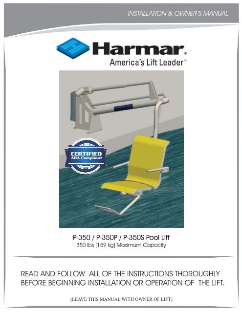
INSTALLATION & OWNER’S <strong>MANUAL</strong><br />
P-350 / P-350P / P-350S Pool Lift<br />
350 lbs [159 kg] Maximum Capacity<br />
READ AND FOLLOW ALL OF THE INSTRUCTIONS THOROUGHLY<br />
BEFORE BEGINNING INSTALLATION OR OPERATION OF THE LIFT.<br />
(LEAVE THIS <strong>MANUAL</strong> WITH OWNER OF LIFT)
TABLE OF CONTENTS<br />
INFORMATION<br />
Product Information ........................................................<br />
Dealer/Installer Information .............................................<br />
2<br />
2<br />
SAFETY SUMMARY<br />
Warnings and Cautions.................................................... 3<br />
PREPARATION<br />
Suggested Tools .............................................................. 4<br />
PRE-INSTALLATION<br />
UNPACKING THE LIFT<br />
ADA Guidelines (USA only) .... ............................................... 5<br />
Path of Travel<br />
With Foot Rest............................................................... 6<br />
With Leg Rest................................................................ 7<br />
Pool Deck Requirements<br />
Acceptable Existing Deck............................................. 8<br />
New Concrete Pad Under Paver and Sand.................. 10<br />
PACKAGE CONTENT ......................................................... 11<br />
INSTALLATION & ASSEMBLY<br />
Charging the Battery....................................................... 12<br />
Anchors and Arm & Base Assembly................................ 13<br />
Seat Support Frame Assembly and Link Shaft................. 14<br />
Seat Assembly................................................................. 15<br />
Foot & Leg Rest Assembly and Adjustment...................... 16<br />
Battery Pack and Control Pendant................................... 17<br />
Portability Kit..................................................................... 18<br />
LIFT OPERATION<br />
TECHNICAL<br />
EXPLODED VIEWS / PARTS LIST<br />
Control Pendant ............................................................ 19<br />
Emergency Buttons........................................................ 20<br />
Maintenance & Care.. .................................................. 21<br />
Troubleshooting Procedure............................................. 22<br />
<strong>P350</strong> Assembly........ ....................................................... 23<br />
Hardware Pack.................. ............................................. 24<br />
Arm & Base Assembly...................................................... 25<br />
Seat Assembly................................................................. 26<br />
Foot Rest Assembly.......................................................... 27<br />
Leg Rest Assembly........................................................... 28<br />
WARRANTY INFORMATION<br />
Warranty................. ........................................................ 29<br />
1
INFORMATION<br />
This manual has been provided to assist you with lift installation and<br />
operation. For further assistance please contact your authorized<br />
<strong>Harmar</strong> dealer or <strong>Harmar</strong>’s Technical Service Department.<br />
<strong>Harmar</strong><br />
2075 47th ST<br />
Sarasota, FL 34234<br />
Tel: 800-833-0478<br />
Tech: 866-378-6648<br />
Fax: 941-308-7399<br />
Email: tech@harmar.com<br />
FILL IN THE FOLLOWING FIELDS TO KEEP FOR YOUR RECORDS:<br />
PRODUCT INFORMATION<br />
Model:______________________________________________<br />
Serial Number:_________________________________________<br />
Purchase Date:_______________________________________<br />
DEALER/INSTALLER INFORMATION<br />
Company Name:____________________________________<br />
Contact Name:______________________________________<br />
Address:____________________________________________<br />
____________________________________________________<br />
Phone Number:______________________________________<br />
Fax Number:________________________________________<br />
Email:______________________________________________<br />
2
SAFETY SUMMARY<br />
!<br />
DANGER - Failure to follow these Warnings, Instructions, and Owner’s Manual<br />
may result in serious injury or death<br />
WARNING<br />
WEIGHT LIMIT: Limit for use is ONE (1) person weighing less than the maximum weight<br />
of 350lb [159kg]. Use only for the transfer of a single user, not as a hoist or crane.<br />
Seat belt is to be used at all times during transfer.<br />
!<br />
CAUTION<br />
BATTERY CHARGE: Always have the battery on the charger charging when not in use. NEVER<br />
leave the battery on the lift when not in use.<br />
DO NOT allow excessive moisture to collect in the battery case. It can affect battery and lift<br />
performance and could lead to battery failure and/or the lift failing to operate.<br />
DO NOT use the seat/seat frame or actuator to move or reposition the lift.<br />
NEVER apply direct water pressure to the electronic components<br />
!<br />
!<br />
Always make sure the area around lift is clear before operating. Never operate the lift with any<br />
person(s) within the operating range of the lift, including on the deck and/or in the water.<br />
ADULT USE ONLY: When in use, the lift is to be operated under the supervison of an adult.<br />
Children should never operate nor play on or around the lift at any time.<br />
NO JUMPING/DIVING/CLIMBING: Do not jump or dive from or climb on the lift.<br />
PINCH/CRUSH HAZARD: Always keep hands, fingers, legs and toes clear of lift arm, base,<br />
and other moving parts when in use.<br />
Save a copy of these instructions in a safe and easily accessible place.<br />
WARNING<br />
Limit for use is one (1) person weighing<br />
less than the maximum weight of<br />
350LB [159KG]<br />
!<br />
!<br />
SIGNAL WORDS<br />
WARNING<br />
CAUTION<br />
DEFINITION<br />
Indicates a hazardous situation<br />
that if not avoided, could result<br />
in moderate to serious injury.<br />
Indicates a hazardous situation<br />
that if not avoided, could result<br />
in moderate to serious property<br />
damage.<br />
3
PREPARATION<br />
SUGGESTED TOOLS<br />
The following is a suggested list of basic tools to have on hand during installation.<br />
<strong>Harmar</strong> lifts are designed to install with as little assembly by the installer as possible.<br />
HAMMER DRILL<br />
TAPE MEASURE<br />
MARKING<br />
IMPLEMENT<br />
MASONRY DRILL BIT<br />
SPECIFICALLY<br />
5/8”<br />
SOCKET SET<br />
SPECIFICALLY<br />
7/16”<br />
3/8”<br />
1/2"<br />
9/16"<br />
3/4”<br />
17mm<br />
WRENCH SET<br />
SPECIFICALLY<br />
7/16”<br />
3/8”<br />
1/2"<br />
9/16”<br />
3/4”<br />
17mm<br />
ALLEN WRENCH<br />
SPECIFICALLY<br />
1/8”<br />
5/32”<br />
3/16”<br />
7/32”<br />
5/16”<br />
3/8”<br />
8mm<br />
SAFETY<br />
GLASSES<br />
HAMMER<br />
FLAT HEAD<br />
SCREWDRIVER<br />
PHILLIPS HEAD<br />
SCREWDRIVER<br />
As always, if you have any questions, concerns or comments, please feel free to contact<br />
<strong>Harmar</strong>'s Technical Service Department at 866-378-6648 or "tech@harmar.com"<br />
4
PRE-INSTALLATION<br />
ADA GUIDELINES (USA only)<br />
Before installing the <strong>P350</strong> Lifts, it is necessary to select the correct location for the Mounting Base. The<br />
<strong>P350</strong> Lifts can be installed in a wide variety of locations, but the owner and installer should be aware of the<br />
regulations set forth by the Americans with Disabilities Act (ADA) with concern to lift installations. Fig. 1<br />
below, shows an example of an ADA compliant installation, which incorporates the following ADA rules in<br />
order to be compliant;<br />
<br />
<br />
<br />
1009.2.1 POOL LIFT LOCATION: Pool lifts must be located where the water level does not exceed<br />
48 inches [1220mm], unless the entire pool is greater than 48” deep.<br />
(<strong>Harmar</strong> requires a minimum pool depth of 40”.)<br />
1009.2.2 SEAT LOCATION: In the raised position, the centerline of the seat shall be located over<br />
The deck and 16 inches [405mm] minimum from the edge of the pool wall. The deck surface<br />
Between the centerline of the seat and the pool edge shall have a slope no greater than 1:48.<br />
1009.2.3 CLEAR DECK SPACE: On the side of the seat opposite the water, a clear deck space shall<br />
be provided parallel with the seat. The space shall be 36 inches [915mm] wide minimum and shall<br />
extend forward 48 inches [1220mm] from a line located 12 inches [305mm] behind the rear edge of<br />
the seat. The clear deck space shall have a slope not greater than1:48.<br />
Fig 1: ADA Deck Requirement<br />
5
PRE-INSTALLATION<br />
PATH OF TRAVEL<br />
WITH FOOT REST<br />
SEAT LOWER SUPPORT<br />
S.L.S MAXIMUM LOAD<br />
LOWER LEG<br />
L.L. MAXIMUM LOAD<br />
10.00<br />
MINIMUM DISTANCE<br />
FROM POOL WALL<br />
17.00<br />
MAXIMUM DISTANCE<br />
FROM POOL WALL<br />
Path of Travel can be used<br />
as an aid to determine<br />
most ideal distance the<br />
pool lift is to be mounted<br />
from the pool wall.<br />
The square and circle<br />
symbols mark the lowest<br />
points on the lift, with no<br />
load, that would be nearest<br />
to the pool wall and<br />
ground during travel.<br />
6
PRE-INSTALLATION<br />
PATH OF TRAVEL<br />
WITH LEG REST<br />
SEAT LOWER SUPPORT<br />
S.L.S MAXIMUM LOAD<br />
LOWER LEG<br />
L.L. MAXIMUM LOAD<br />
10.00<br />
MINIMUM DISTANCE<br />
FROM POOL WALL<br />
17.00<br />
MAXIMUM DISTANCE<br />
FROM POOL WALL<br />
Path of Travel can be used<br />
as an aid to determine<br />
most ideal distance the<br />
pool lift is to be mounted<br />
from the pool wall.<br />
The square and circle<br />
symbols mark the lowest<br />
points on the lift, with no<br />
load, that would be nearest<br />
to the pool wall and<br />
ground during travel.<br />
7
PRE-INSTALLATION<br />
POOL DECK REQUIREMENTS<br />
Fig 2: Minimum Deck Requirements<br />
Fig 3: Lift Location and Hole Specifications<br />
Minimum Deck Requirement:<br />
Minimum concrete slab should be at least 60” x 42” x 4.00” thick, reinforced<br />
(#4 rebar) with a concrete strength of 3000PSI.<br />
Anchors must be installed a minimum of 4” or greater from the edge of the slab<br />
Existing slab does not exhibit any signs of cracking or deterioration.<br />
For proper installation into an existing deck, follow these guidelines.<br />
1<br />
2<br />
To determine the proper area to install the lift, follow the ADA guidelines, Fig. 1.<br />
Verify that the pool deck meets the minimum requirements above, also see Fig.2. If the deck does not<br />
meet these requirements, then the deck needs to be cut and replaced with a new slab that meet these<br />
requirements. The new slab needs to be reinforced with rebar and adhered with epoxy into the<br />
remaining existing deck. Simpson SET epoxy is recommended or equivalent for installation.<br />
!<br />
WARNING<br />
When operating equipment, operator should ALWAYS wear<br />
Personal Protective Equipment<br />
8
PRE-INSTALLATION<br />
Fig 5: Mark hole locations<br />
PARALLEL<br />
POOL<br />
WALL<br />
Fig 4: Lift base parallel with pool wall<br />
Fig 6: Drill four holes<br />
3<br />
4<br />
5<br />
6<br />
Due to Local Electrical Code, it maybe necessary to Bond the Mounting Base to the pools Bonding<br />
Grid with 8ga Copper Wire. See Fig. 2&3forlocation. Check your Local Electrical Code for proper<br />
Bonding.<br />
To determine the proper location to install the lift, use Fig. 3 and the Arm & Base assembly as a<br />
template. Make sure that the lift is an appropriate distance away from the pool wall and that all holes<br />
to be drilled are at least 4” away from any edge of the deck or slab. DO NOT lift the assembly from<br />
the actuator.<br />
Mark the four (4) hole locations of the base onto the deck, being sure that the Base is parallel with the<br />
pool wall and the Arm is facing the correct direction, Fig. 4&5.<br />
Using the Hammer Drill and 5/8 Masonry Drill Bit, drill the four 5/8” diameter holes 2.00” deep.<br />
Make sure the Drill is square to the deck and drill straight down, Fig. 6. Use the Shop Vac to remove<br />
additional dust from holes and surrounding areas.<br />
! CAUTION DO NOT drill too deep or the anchors will be too low for the supplied fasteners.<br />
!<br />
WARNING<br />
When operating equipment, operator should ALWAYS wear<br />
Personal Protective Equipment<br />
9
PRE-INSTALLATION<br />
PAVER & SAND REQUIREMENTS<br />
DETERMINING THE LENGTH & WIDTH OF THE RISER<br />
[Hr] is the Height of the Riser<br />
[Lr] is the Length of the Riser<br />
[Wr] is the Width of the Riser<br />
Hr = (Height of Sand) + (Thickness of Paver)<br />
Lr=(Hrx2)+12<br />
Wr=(Hrx2)+10<br />
EXAMPLE:<br />
Sand = 2.00” deep and Paver = 3.00” thick<br />
Hr=2+3=5.00”<br />
Lr = (5.00 x 2) + 12 = 22.00”<br />
Wr = (5.00 x 2) + 10 = 20.00”<br />
Fig 8: Calculation of Risers length and width<br />
Fig 7: Concrete requirements for Paver & Sand App<br />
1<br />
2<br />
3<br />
4<br />
5<br />
To determine the proper area to install the lift, Fig 9: Reinforcement of concrete<br />
Follow the ADA guidelines, Fig. 1.<br />
The minimum deck requirements are similar to those on page 7, but this application requires a Riser in<br />
addition to the footing, Fig. 7. Remove the pavers & sand from the location chosen for the lift and cut<br />
out the underlying foundation. Replace with a new slab with a Riser incorporated on top of it, Fig. 7.<br />
Use Fig. 8 to determine the correct size of the Riser. The new slab needs to be reinforced with rebar<br />
and adhered with epoxy into the remaining existing deck, Fig. 9. Simpson SET epoxy is recommended<br />
or equivalent for installation.<br />
Due to Local Electrical Code, it maybe necessary to Bond the Mounting Base to the pools Bonding<br />
Grid with 8ga Copper Wire. See Fig. 7 for location. Check your Local Electrical Code for proper<br />
Bonding.<br />
The proper location to install the lift is centered on the riser, use Fig. 7 and the Arm & Base assembly<br />
as a template. Make sure that the lift is an appropriate distance away from the pool wall. DO NOT<br />
lift the assembly from the actuator.<br />
Return to page 8 and follow Steps5&6tofinish preparations.<br />
!<br />
WARNING<br />
When operating equipment, operator should ALWAYS wear<br />
Personal Protective Equipment<br />
10
UNPACKING THE LIFT<br />
PACKAGE CONTENT<br />
Be sure to check the contents of the boxes against the package checklist,<br />
verifying all parts are included with the lift for a proper installation. If<br />
any parts are missing or damaged, immediately contact the distributor<br />
from which you purchased the lift. DO NOT attempt to install or use<br />
the lift with any missing or damaged parts.<br />
!<br />
WARNING<br />
NEVER attempt to lift the boxes from the ground<br />
or on/off a vehicle by yourself. Serious injuries<br />
or damage to equipment may result.<br />
OR<br />
LEG REST<br />
ASSEMBLY<br />
(P-350S)<br />
FOOT REST<br />
ASSEMBLY<br />
(P-350)<br />
SEAT<br />
ASSEMBLY<br />
ARM & BASE<br />
ASSEMBLY<br />
CONTROL<br />
PENDANT<br />
SEAT SUPPORT<br />
FRAME<br />
HARDWARE<br />
PACK<br />
CHARGER<br />
MOUNTING<br />
BRACKET<br />
CHARGER<br />
11
INSTALLATION & ASSEMBLY<br />
CHARGING THE BATTERY<br />
Before using the pool lift for the first time, the 24V Battery must be fully charged. The battery should be<br />
charged for a minimum of 24 hours on its first initial charge. The battery can be left on the Battery Charger<br />
overnight or until it is needed for use. It is recommended that the battery be fully charged before each use to<br />
ensure that the lift will function for the duration of its immediate use. The battery should never stay on the<br />
lift if the lift is not being used.<br />
1 Installing 24V Battery onto Battery Charger:<br />
Place Battery onto Battery Charger and rotate up until the Battery engages the Mounting Bracket.<br />
The latch on the Battery will click when engaged properly and will be fixed tightly on top of the<br />
Charger. When the Charger is plugged in, the “ON” light will illuminate GREEN. When the<br />
Battery is properly mounted onto the Charger, the “Charge” light will illuminate ORANGE.<br />
Once the Battery is FULLY charged, the “Charge” light will turn off and the Battery is ready<br />
to be used.<br />
24V<br />
BATTERY<br />
MOUNTING<br />
BRACKET<br />
CLICK<br />
BATTERY<br />
CHARGER<br />
2 Recharging 24V Battery<br />
To recharge the Battery, grip the top-rear of<br />
of the Battery and squeeze the clip. This will<br />
unlatch the Battery from the Mounting Bracket.<br />
The Battery can now be installed onto the<br />
Battery Charger as described above.<br />
Mounting<br />
Bracket<br />
24V<br />
Battery<br />
!<br />
CAUTION<br />
ALWAYS have the Battery charging<br />
on the Charger when not in use.<br />
12
INSTALLATION & ASSEMBLY<br />
ARM & BASE ASSEMBLY<br />
1/2-13 x 0.75<br />
HEX HEAD<br />
(x4)<br />
½ SPLIT LOCK<br />
WASHER<br />
(x4)<br />
DROP-IN<br />
ANCHOR<br />
(x4)<br />
!<br />
CAUTION<br />
Anchor must be set flush or<br />
slightly below surface<br />
ARM & BASE<br />
ASSEMBLY<br />
3 Insert Drop-In Anchors<br />
Before inserting the Drop-In Anchors, apply a small<br />
amount of Epoxy into the four anchor holes and to the<br />
outside of the anchors. Insert the Drop-In Anchors into<br />
the holes and gently tap them in being careful not to<br />
damage the thread (they should sit flush with or just<br />
below the deck). Once in place, using the Setting Tool,<br />
forcefully strike the inside of the anchors to set them.<br />
APPLY<br />
SMALL<br />
AMOUNT<br />
OF<br />
EPOXY<br />
TO HOLES<br />
& ANCHORS<br />
INSERT<br />
SETTING<br />
TOOL<br />
! CAUTION<br />
DO NOT apply too much Epoxy<br />
!<br />
CAUTION<br />
DO NOT lift from the Actuator<br />
4 Fasten Arm & Base Assembly<br />
Align mounting holes with anchors, and tightly<br />
fasten with spring lock washer and bolts.<br />
5 Attach Copper Wire<br />
Fasten copper wire to Grounding Lug located<br />
within the Base of the assembly.<br />
CHECK LOCAL ELECTRICAL CODE<br />
GROUNDING<br />
LUG<br />
8GA<br />
COPPER WIRE<br />
13
INSTALLATION & ASSEMBLY<br />
6<br />
Attach Seat Support Frame<br />
RIGHT<br />
HAND<br />
FLANGE<br />
BEARING<br />
(x2)<br />
LEFT<br />
HAND<br />
The <strong>P350</strong> has ambidextrous seating which<br />
allows the seat to be set to face either side<br />
of the pool dependant on pool installion<br />
and/or preference, shown to the left.<br />
SEAT SUPPORT<br />
FRAME<br />
Once chosen, grease the surfaces<br />
of the Flange Bearings and the Seat<br />
Support Frame, if necessary, as shown<br />
in the picture. Insert the Flange Bearings<br />
into the Arm and insert the Seat Support<br />
Frame into the bearings, below.<br />
RIGHT<br />
HAND<br />
ADD<br />
GREASE<br />
ARM & BASE<br />
ASSEMBLY<br />
INSERT INSERT<br />
7 Link Shaft Adjustment<br />
The Link shaft should be attached and fastened on<br />
the opposite side of the Seat Support Frame. If this<br />
is not the case, then simple unfasten the Link Shaft<br />
and attach it onto the otherside of the base.<br />
3/8-16<br />
NYLON<br />
NUT<br />
LINK<br />
SHAFT<br />
BASE<br />
3/8<br />
NYLON<br />
WASHER<br />
3/8-16 x 1.50<br />
SOCKET<br />
HEAD<br />
8 Attach Rotation Plate<br />
1/2-13<br />
NYLON<br />
NUT<br />
3/8-24 x 1<br />
BUTTON<br />
HEAD W/<br />
NYLON<br />
PATCH<br />
Rotate the Rotation Plate forward and<br />
fasten to Seat Support Frame with the<br />
appropriate fasteners.<br />
ROTATION<br />
PLATE<br />
SPRING<br />
LOCK<br />
WASHER<br />
14
INSTALLATION & ASSEMBLY<br />
9<br />
Attach Seat Assembly<br />
Rest Seat Assembly onto Seat Support<br />
Frame, align holes, and tightly fasten<br />
with respective fasteners.<br />
SEAT<br />
ASSEMBLY<br />
1/4-20 x 2.00<br />
BUTTON HEAD<br />
(x2)<br />
1/4-20<br />
NYLON NUT<br />
(x4)<br />
¼ WASHER<br />
(x2)<br />
1/4-20 x 1.50<br />
BUTTON HEAD<br />
(x2)<br />
!<br />
CAUTION<br />
DO NOT unfasten or disassemble Seat from Back & Lower Supports.<br />
SEAT<br />
BACK<br />
SUPPORT<br />
ASSEMBLY<br />
LOWER<br />
SUPPORT<br />
15
INSTALLATION & ASSEMBLY<br />
3/8-16 X 2.50<br />
BUTTON HEAD<br />
(x2)<br />
LOWER SEAT<br />
SUPPORT<br />
3/8-16<br />
NYLON NUT<br />
(x2)<br />
10 Attach Foot & Leg Rest Assembly<br />
The foot rest, shown, and leg rest are designed<br />
to be ambidextrous, to allow for right & left<br />
hand seating. The Foot & Leg Rest should<br />
always be on the side nearest to the water. To<br />
attach the Assembly, simply align the holes on<br />
the Foot & Leg Rest Assembly with that of the<br />
Lower Seat Support and fasten with the supplied<br />
hardware.<br />
FOOT REST<br />
ASSEMBLY<br />
LEG REST<br />
ASSEMBLY<br />
11<br />
Foot & Leg Rest Adjustment<br />
The Foot Rest has two setting, high and low,<br />
and the Leg Rest has three settings, high,<br />
medium, and low, depending on the desired<br />
height. To adjust the height of the Foot Rest,<br />
remove the bolt, adjust the height up or<br />
down, align the holes at the desired height,<br />
reinsert the bolt into the correct hole, as<br />
shown, and fasten.<br />
FOOT REST BOLT SETTINGS<br />
(Bolt Location)<br />
HIGH<br />
1/2-13 X 2.50<br />
BUTTON HEAD<br />
LOW<br />
1/2-13<br />
NYLON NUT<br />
LEG REST BOLT SETTINGS<br />
(Bolt Location)<br />
H M L<br />
H M L<br />
16
INSTALLATION & ASSEMBLY<br />
12<br />
Installing 24V Battery onto Lift:<br />
Place FULLY charged Battery onto Control Box<br />
and lift up until the Battery engages the Mounting<br />
Bracket. The latch on the Battery will click when<br />
engaged properly and will be fixed tightly on top<br />
of the Control Box.<br />
CLICK<br />
Mounting<br />
Bracket<br />
24V<br />
Battery<br />
Control Box<br />
!<br />
WARNING<br />
ALWAYS detach the Battery when NOT in use and<br />
place onto the Charger to ensure a FULLY operating<br />
Battery when needed<br />
Actuator<br />
13<br />
Connecting Control Pendant:<br />
Insert Control Pendant plug into Control Box port by aligning<br />
key on plug with key way on the port. This will ensure that the<br />
pins on the plug align with that if the Control Box. Press firmly to<br />
ensure that the plug is fully seated within the port. Also, firmly<br />
press in the actuator plug to ensure that it is seated properly into<br />
its respective port.<br />
Control<br />
Pendant<br />
Control Box<br />
Control<br />
Pendant<br />
Plug<br />
Actuator<br />
Plug<br />
Plugs<br />
Fully<br />
Seated<br />
!<br />
WARNING<br />
Lift WILL NOT operate if the Control Pendant and/or the actuator plugs<br />
are NOT fully seated within their respective ports of the Control Box.<br />
17
INSTALLATION & ASSEMBLY<br />
PORTABILITY KIT<br />
[included with P-350P]<br />
This kit is designed to allow the user/owner to transport the pool lift, <strong>P350</strong>, when not in<br />
use, to and from storage. Be sure to check the contents of the package and verify that all<br />
parts and hardware are present before installing. If any parts are missing contact the<br />
distributor from which the kit/lift was purchased.<br />
1/2” WASHER (x2)<br />
HAIR PIN (x2)<br />
PARTS & HARDWARE<br />
1/2-13 X 1.00<br />
BUTTON HEAD<br />
(x4)<br />
1/2” WASHER<br />
(x4)<br />
1/2” LOCK NUT<br />
(x4)<br />
STAND<br />
TOOL REQUIRED<br />
RACHET<br />
3/4” SOCKET<br />
3/32 ALLEN<br />
5/16 ALLEN<br />
8-32 X 1/2”<br />
BUTTON HEAD<br />
(x2)<br />
#8 EXT WASHER (x2)<br />
WHEEL<br />
BRACKET<br />
PULL HANDLE<br />
WHEEL (x2)<br />
!<br />
CAUTION<br />
INSTALLATION<br />
Align all parts with respective holes and tighten<br />
all fasteners. The Stand is to be installed on the<br />
same side as the seat and the Wheel Bracket<br />
Assembly & Pull Handle on the opposing side.<br />
The lift should never be operated when not fastened to the deck or in storage.<br />
Lift should always be in its most up position when moved and/or stored.<br />
Items should never be rested on the lift or seat when not in use.<br />
STAND WHEEL BRACKET ASSEMBLY PULL HANDLE<br />
18
LIFT OPERATION<br />
BEFORE OPERATING THE LIFT:<br />
1<br />
2<br />
3<br />
4<br />
5<br />
Always make sure that the area around the lift is clear before operating.<br />
Never operate the lift with any person within the operating range of the lift, including<br />
the deck and/or water.<br />
DO NOT allow anyone to operate the lift without adult supervision.<br />
DO NOT allow children to play on or around the lift at any time.<br />
Check all fasteners and joints for tightness and wear before each use.<br />
OPERATING THE LIFT<br />
DOWN<br />
UP<br />
To move the lift into the pool,<br />
press and hold the DOWN<br />
button on the Control Pendant.<br />
To STOP moving, release<br />
the button at the desired<br />
depth.<br />
To move the lift out of the pool,<br />
press and hold the UP button<br />
on the Control Pendant.<br />
To STOP moving, release<br />
the button once the lift is at<br />
its highest point or has stopped.<br />
!<br />
CAUTION<br />
If the “DOWN” button is NOT released, the lift will<br />
continue to a depth below the crest of the water.<br />
UP<br />
DOWN<br />
!<br />
CAUTION<br />
Lift is ALWAYS to be operated under the direct supervision of an Able-Bodied Adult.<br />
19
LIFT OPERATION<br />
EMERGENGY<br />
“STOP” BUTTON<br />
EMERGENCY BUTTONS<br />
On the front of the Control Box there are two emergency<br />
buttons, “EMERGENCY STOP” & “EMERGENGY UP.”<br />
EMERGENCY<br />
“UP” BUTTON<br />
DEPRESS<br />
CLICK<br />
TURN<br />
CLOCKWISE<br />
1<br />
Emergency “STOP” Button:<br />
The Emergency Stop Button is the larger red button on the<br />
front of the Control Box. To ENABLE the “Emergengy Stop”<br />
button, depress the button so it clicks and locks in its depressed<br />
position. This will disable the lift and stop it immediately at the<br />
location in which the Emergency Button was depressed. The<br />
button will remain locked until it is released.<br />
!<br />
WARNING<br />
The lift WILL NOT function until the<br />
Emergency Button has been released.<br />
To RELEASE the “Emergency Stop” button and resume operation<br />
of lift, simply turn the button clockwise until the it pops out.<br />
2<br />
Emergency “UP” Button:<br />
The Emergency Up Button is the small<br />
recessed button located next to the word<br />
“EMERGENCY” on the front of the Control<br />
Box. To use; take a pen, pencil, or any object<br />
with a point, depress the button, and hold until<br />
the lift is all the way up. This will bypass the<br />
Control Pendant and raise the lift.<br />
DEPRESS<br />
!<br />
WARNING<br />
This function will only work if the Battery is sufficiently<br />
charged, properly attached, and if the Control Box is<br />
operating properly.<br />
20
TECHNICAL<br />
MAINTENANCE & CARE<br />
The lift should be cleaned routinely to ensure the life and integrity of the lift. Cleaning product is entirely<br />
up to the owner as there are many to choose from. For routine cleaning, it is recommended to use gentle<br />
soaps, detergents, or a diluted mixture of ammonia. If scrubbing is required for tough stains, use a soft<br />
scrub with brisk rubbing.<br />
DAILY USE:<br />
If the lift is used daily, be sure to wash the lift at the end of each day. Wash the lift with fresh water a mild<br />
soap and a soft cloth. Do not use bristled brushes or steel wools to clean the lift as it will scrap off the<br />
powder coating. Check that the lift is working properly and then place the battery on the charger. It is<br />
recommended that the battery be charged after every use.<br />
WEEKLY USE:<br />
If the lift is used weekly, follow the same procedure as above. Also be sure to check all of the contact points<br />
(terminals) for damage or corrosion. If you notice corrosion gently clean the terminals. To clean corrosion<br />
from the terminals use a q-tip and some rubbing alcohol. If the corrosion is particularly stubborn try using a<br />
3M scotch brite pad, but be careful not to damage the terminals. Apply dielectric grease to the terminals<br />
after cleaning them. This will help to prevent further corrosion. Do not leave the battery on the lift when not<br />
in use. Always store the battery on the charger whenever the lift is not being used.<br />
MONTHLY USE:<br />
If the lift is used monthly, follow the same steps as above. Also check the nuts and bolts to make sure they<br />
are securely fastened (this is always a good idea, no matter how often or infrequently the lift is used). Also<br />
make sure to store the battery on the charger and not on the lift. Leaving the battery on the lift for extended<br />
periods will significantly shorten the battery’s life span.<br />
STORED/OCCASIONAL USE:<br />
If the lift is not used often and is stored for an extended period of time, follow all of the steps above. Check<br />
for rusting at all crevice, weld points, and fasteners. If you notice rusting spray some WD-40 on the affected<br />
area and take a 3M scotch brite pad and rub briskly. Afterwards be sure to wash and rinse the lift again with<br />
soap and fresh water. When storing the lift make sure it is in a dry area and covered. DO NOT STORE in or<br />
around pool chemicals.<br />
!<br />
CAUTION<br />
ALWAYS clean the lift with FRESH water only.<br />
NEVER use the pool or chemically treated water for cleaning.<br />
21
TECHNICAL<br />
TROUBLESHOOTING PROCEDURE<br />
**THE BATTERY SHOULD BE FULLY CHARGED BEFORE TROUBLESHOOTING**<br />
Issue: Lift stopped moving over the water.<br />
1<br />
Procedure: Push the “EMERGENCY” BUTTON.<br />
If the lift gets stuck over or in the water and the Control<br />
Pendant does not raise the lift, then using a pen, pencil,<br />
or pointed object, depress the button located on the<br />
Control Box next to the word “EMERGENCY”. This<br />
will bypass the Control Pendant and raise the lift. If this<br />
does not raise the lift, then the remote may be fine and the<br />
problem is with either the Battery, Control Box, or damaged<br />
cables.<br />
DEPRESS<br />
Issue: Lift will not operate, when buttons on control pendant is pressed.<br />
1<br />
Procedure:<br />
Check Cable Connections to Control Box.<br />
Check underneath the Control Box to be sure that all cables<br />
are properly seated within their respective ports. The plugs<br />
should be recessed within those ports. Verify by unplugging<br />
both the Control Pendant and the Actuator cables. Check that<br />
there is no corrosion or damage to the connectors/pins. Plug the<br />
Control Pendant back into the Control Box by aligning key<br />
on plug with key way on the port. Press in firmly to ensure<br />
that the plug is fully seated within the port. For the actuator,<br />
insert the cables jack into its port and press in firmly.<br />
Check For<br />
Corrosion<br />
Before<br />
Plugging In<br />
2<br />
Procedure:<br />
Check Battery Connections.<br />
Check that the Battery Pack is properly secured onto the<br />
Mounting Bracket. The Battery pack should be locked<br />
in place with nearly no movement if shaken. Verify by<br />
unlatching from Mounting Bracket. Check that there is<br />
no corrosion or damage to the terminals on the Battery<br />
Pack and Control Box. If corroded or dirty, clean off<br />
using rubbing alcohol. Once cleaned, it is recommended<br />
to add dielectric grease to the terminals to prevent corrosion<br />
and to ensure good electrical contact. Reinstall the Battery<br />
Pack onto the Control Box. When properly engaged onto the<br />
Mounting Bracket, the latch on the back of the Battery<br />
Pack will “CLICK”. If lift fails to lift, then try another fully<br />
charged battery. If lift still fails to operate, then the Control Box<br />
will need to be replaced. Contact an Autorized lift dealer for<br />
component replacement.<br />
Plugs<br />
Fully<br />
Seated<br />
CLICK<br />
!<br />
CAUTION<br />
The lift WILL NOT function if the Battery is not<br />
charged or if the Control Box is damaged or<br />
malfunctioning.<br />
22
EXPLODED VIEW / PARTS LIST<br />
<strong>P350</strong> ASSEMBLY<br />
3<br />
2<br />
5<br />
1<br />
4<br />
ASSEMBLY PARTS<br />
ITEM QTY PART NO. DESCRIPTION<br />
1 1 210-2L02-C SEAT SUPPORT FRAME<br />
2 1 N/A ARM & BASE ASSEMBLY<br />
3 1 N/A SEAT ASSEMBLY<br />
4 1 N/A FOOT REST ASSEMBLY<br />
5 1 H00-2A05-A HARDWARE PACK<br />
23
EXPLODED VIEW / PARTS LIST<br />
HARDWARE PACK<br />
8<br />
4<br />
5<br />
2<br />
4<br />
2<br />
6<br />
2<br />
7<br />
1<br />
14<br />
4<br />
11<br />
1<br />
1<br />
4<br />
9<br />
4<br />
12<br />
2<br />
10<br />
2<br />
13<br />
1<br />
3<br />
1<br />
2<br />
1<br />
ASSEMBLY PARTS<br />
ITEM QTY PART NO. DESCRIPTION<br />
1 4 540-2L03-A 1/2-13 DROP IN ANCHOR<br />
2 1 902-3L05-A OWNERS <strong>MANUAL</strong><br />
3 1 SB1-037-2-6_50 3/8 DIA X 6.50" L<br />
4 2 BHCS-0_25-20--1_50-SS BUTTON HEAD, 1/4-20 X 1.50, SS<br />
5 2 BHCS-0_25-20--2_00-SS BUTTON HEAD, 1/4-20 X 2.00, SS<br />
6 2 BHCS-0_37-16--2_50-SS BUTTON HEAD, 3/8-16 X 2.50, SS<br />
7 1 BHCS-0_37-24--1_00-NP-SS BUTTON HEAD W/ NYLON PATCH, 3/8-24 X 1.00, SS<br />
8 4 HHCS-0_50-13--0_75-SS HEX HEAD, 1/2-13 X 0.75, SS<br />
9 4 NUT-0_25-20-NYLOCK-SS NYLOCK NUT, 1/4-20 , SS<br />
10 2 NUT-0_37-16-NYLOCK-SS NYLOCK NUT, 3/8-16, SS<br />
11 1 NUT-0_50-13-NYLOCK-NTE-SS NYLOCK NUT, THIN, 1/2-13, SS<br />
12 2 WASH-0_25-0_62--0_04-RH-SS WASHER, FLAT, 1/4", SS<br />
13 1 WASH-0_37-0_68--0_09-SL-SS WASHER, SPRING LOCK, 3/8 ID, SS<br />
14 4 WASH-0_50-0_87--0_12-SL-SS SPLIT LOCK WASHER 1/2, SS<br />
24
EXPLODED VIEW / PARTS LIST<br />
ARM & BASE ASSEMBLY<br />
23<br />
26<br />
7<br />
26<br />
24<br />
20<br />
8<br />
12<br />
23<br />
11 12<br />
25<br />
26<br />
17<br />
13<br />
22<br />
3<br />
2<br />
18<br />
13<br />
27<br />
19<br />
21<br />
22<br />
26<br />
15<br />
5<br />
16<br />
17<br />
14<br />
6<br />
19<br />
10<br />
1<br />
4<br />
21<br />
20<br />
9<br />
27<br />
18<br />
ASSEMBLY PARTS<br />
ITEM QTY PART NO. DESCRIPTION<br />
1 1 200-2L05-C BASE WELDED ASSEMBLY<br />
2 1 201-2L02-C ARM<br />
3 1 201-2L05-C SPACER WELDED ASSEMBLY<br />
4 1 299-2L02-A COPPER SET SCREW LUG<br />
5 1 320-2L02-A BATTERY PACK<br />
6 1 321-2L02-A CONTROL BOX<br />
7 1 517-2L02-C ROTATION PLATE<br />
8 1 531-2L02-C LINK SHAFT<br />
9 1 557-2L02-A ARM PIN<br />
10 1 599-2L02-A CONTROL MOUNTING BRACKET<br />
11 1 801-2L02-A ACTUATOR<br />
12 2 ALA05010 FLANGE BEARING 2 INCH<br />
13 2 ALA15110 BRONZE FLANGE BUSHING, 1"<br />
14 1 ALA21094 STICKER, "CAUTION"<br />
ASSEMBLY PARTS<br />
PART NO.<br />
DESCRIPTION<br />
15 1 910-2L02-A STICKER<br />
16 1 ALA99995 LABEL, SERIAL NUMBER<br />
17 2 BHCS-0_25-20--0_37-NP-SS BUTTON HEAD W/NYLON PATCH, 1/4-20 X 0.37, SS<br />
18 2 BHCS-0_50-13--0_75-NP-SS BUTTON HEAD W/ NYLON PATCH, 1/2-13 X 0.75, SS<br />
19 2 BHCS-10-24--0_62-SS BUTTON HEAD, 10-24 X 0.62, SS<br />
20 2 NUT-0_37-16-NYLOCK-SS NYLOCK NUT, 3/8-16, SS<br />
21 2 NUT-10-24-NYLOCK-SS NUT, NYLOCK, 10-32, SS<br />
22 2 NUT-M10-1_5-NYLOCK-SS NYLOCK NUT, M10 X 1.5, SS<br />
23 2 SHCS-0_37-16--1_50-SS SOCKET HEAD, 3/8-16 X 1.50, SS<br />
24 1 SHCS-M10-1_5--55MM-SS SOCKET HEAD, M10-1.5 X 55, SS<br />
25 1 SHCS-M10-1_5-130MM-SS SOCKET HEAD CAP SCREW M10-1.5 X 130MM , SS<br />
26 4 WASH-0_37-1_00-0_05-N WASHER, 0.40 ID X 1.00 OD X 0.05, WHITE NYLON<br />
27 2 WASH-0_50-1_37-0_12-RH-SS WASHER, FLAT, 1/2", SS<br />
25
EXPLODED VIEW / PARTS LIST<br />
SEAT ASSEMBLY<br />
3<br />
2<br />
4<br />
2<br />
16<br />
1<br />
7<br />
2<br />
16<br />
1<br />
14<br />
1<br />
9<br />
1<br />
13<br />
2<br />
14<br />
1<br />
11<br />
2<br />
2<br />
1<br />
10<br />
2<br />
15<br />
5<br />
6<br />
1<br />
5<br />
2<br />
9<br />
3<br />
8<br />
1<br />
17<br />
2<br />
12<br />
4<br />
12<br />
1<br />
15<br />
1<br />
12<br />
1<br />
15<br />
1<br />
15<br />
1<br />
1<br />
1<br />
ASSEMBLY PARTS<br />
ITEM QTY PART NO. DESCRIPTION<br />
1 1 204-2L02-C SEAT LOWER SUPPORT<br />
2 1 213-2L02-C BACK BRACKET<br />
3 2 214-2L02-C ARMREST<br />
4 2 410-2L02-A PLUG (1" DIA RND TUBE)<br />
5 2 542-2L02-C PLATE<br />
6 1 900-2L02-A SEAT<br />
7 2 906-2L02-A RUBBER BUMPER<br />
8 1 911-3L02-A SEAT BELT<br />
9 4 SPCR-0_25-0_50--0_18-N SPACER, 1/4 ID X 0.18, NYLON<br />
10 2 ALA25025FP END CAPS<br />
11 2 BHCS-0_25-20--1_25-SS BUTTON HEAD, 1/4-20 X 1.25, SS<br />
12 6 BHCS-0_25-20--1_50-SS BUTTON HEAD, 1/4-20 X 1.50, SS<br />
13 2 BHCS-0_25-20--2_50-SS BUTTON HEAD, 1/4-20 X 2.50, SS<br />
14 2 BHCS-0_31-18--1_75-SS BUTTON HEAD, 5/16-18 X 1.75, SS<br />
15 8 NUT-0_25-20-NYLOCK-SS NYLOCK NUT, 1/4-20 , SS<br />
16 2 NUT-0_31-18-NYLOCK-SS NYLOCK, 5/16-18, SS<br />
17 2 WASH-0_25-0_62--0_04-RH-SS WASHER, FLAT, 1/4", SS<br />
26
EXPLODED VIEW / PARTS LIST<br />
FOOT REST ASSEMBLY<br />
11<br />
3<br />
12<br />
8<br />
11<br />
9<br />
4<br />
8<br />
7<br />
6<br />
2<br />
10<br />
1<br />
10<br />
13<br />
5<br />
13<br />
13<br />
7<br />
13<br />
13<br />
13<br />
ASSEMBLY PARTS<br />
ITEM QTY PART NO. DESCRIPTION<br />
1 1 410-2L02-A PLUG (1" DIA RND TUBE)<br />
2 1 211-2L02-C FOOT PLATE SUPPORT<br />
3 1 212-2L02-C HOUSING WELDMENT<br />
4 1 416-2L02-A FOOT PLATE<br />
5 1 567-2L02-C LOWER LEG TUBE<br />
6 1 568-2L02-C UPPER LEG TUBE<br />
7 2 BHCS-0_25-20--1_50-SS BUTTON HEAD, 1/4-20 X 1.50, SS<br />
8 2 BHCS-0_37-16--2_50-SS BUTTON HEAD, 3/8-16 X 2.50, SS<br />
9 1 BHCS-0_50-13--2_50-SS BUTTON HEAD, 1/2-13 X 2.50, SS<br />
10 2 NUT-0_25-20-NYLOCK-NTE-SS NYLOCK NUT, THIN, 1/4-20, SS<br />
11 2 NUT-0_37-16-NYLOCK-SS NYLOCK NUT, 3/8-16, SS<br />
12 1 NUT-0_50-13-NYLOCK-NTE-SS NYLOCK NUT, THIN, 1/2-13, SS<br />
13 6 PHTS-10-32--0_37-SS PAN HEAD, THREAD FORMING, 10-32 X 0.37, SS<br />
27
EXPLODED VIEW / PARTS LIST<br />
LEG REST ASSEMBLY<br />
2<br />
1<br />
12<br />
1<br />
9<br />
1<br />
3<br />
1<br />
10<br />
1<br />
7<br />
1<br />
14<br />
1<br />
8<br />
1<br />
1<br />
1<br />
13<br />
6<br />
5<br />
1<br />
6<br />
1<br />
4<br />
1<br />
11<br />
1<br />
ASSEMBLY PARTS<br />
ITEM QTY PART NO. DESCRIPTION<br />
1 1 200-3L12-C LEG PLATE SUPPORT<br />
2 1 212-2L02-C FOOT REST HOUSING<br />
3 1 400-3L12-A LEG REST<br />
4 1 410-2L02-A PLUG (1" DIA RND TUBE)<br />
5 1 500-3L12-C UPPER LEG TUBE<br />
6 1 501-3L12-C LOWER LEG TUBE<br />
7 1 ALA16031 FAST PIN CHAIN<br />
8 1 BHCS-0_25-20--1_50-SS BUTTON HEAD, 1/4-20 X 1.50, SS<br />
9 1 BHCS-0_50-13--2_50-SS BUTTON HEAD, 1/2-13 X 2.50, SS<br />
10 1 H106600 HOV SWA SAFETY PIN<br />
11 1 NUT-0_25-20-NYLOCK-NTE-SS NYLOCK NUT, THIN, 1/4-20, SS<br />
12 1 NUT-0_50-13-NYLOCK-NTE-SS NYLOCK NUT, THIN, 1/2-13, SS<br />
13 6 PHTS-10-32--0_37-SS PAN HEAD, THREAD CUTTING, 10-32 X 0.37, SS<br />
14 1 RIV-188-SS RIVET<br />
28
WARRANTY INFORMATION<br />
POOL LIFTS THREE YEAR NON-TRANSFERABLE LIMITED WARRANTY<br />
<strong>Harmar</strong> warrants ONLY to the original purchaser of the product manufactured by <strong>Harmar</strong>,<br />
assembled and installed in accordance with <strong>Harmar</strong>’s assembly and installation instructions,<br />
properly used and maintained, shall be free from defects in material and workmanship for a<br />
period of three (3) years from the date of original purchase, with the exception of the following<br />
items: Battery Pack and Seat each have a one (1) year warranty from the date of original<br />
purchase.<br />
The Pool Lift has a three (3) year warranty on the frame/mechanical, electrical & motor<br />
components, excluding powder coated paint finish, which may become scratched or<br />
chipped with normal use. The Battery Pack and Seat, including seat frame, spreader bars,<br />
sling, and powder coat paint finish have a one (1) year warranty. Within the warranty period,<br />
<strong>Harmar</strong> will repair or replace any item deemed to be found defective. Normal maintenance<br />
and care of the unit, including charging the battery when not in use is recommended.<br />
IMPORTANT: Weight capacity of pool lift seat and its seat support frame is NOT to exceed the<br />
MAXIMUM LIFTING CAPACITY of 350 lb [159 kg].<br />
The warranty is non-transferable and is subject to the following terms and conditions:<br />
<strong>Harmar</strong> shall not be responsible for the cost of removal or replacement of any defective <strong>Harmar</strong> product, nor for any<br />
other expenses or for damages which might be incurred in such removal or replacement.<br />
This warranty specifically excludes fading or staining of material, rust or corrosion of any metallic material, and<br />
cleaning of <strong>Harmar</strong> products.<br />
This warranty relates only to defects in material and workmanship and DOES NOT cover any damages or failures<br />
resulting from other causes, including, but not limited to Acts of God, misuse or abuse, accident or negligence, fire,<br />
improper assembly or installation, chipping or flaking of powder coating, weather damages, including ice and sand,<br />
improper maintenance of any products, or normal wear and tear from day to day use.<br />
Damages induces by the improper use of chemicals is not covered by this warranty.<br />
In the event that any products are altered, repaired, or improperly installed or improperly used by anyone without<br />
prior written approval by <strong>Harmar</strong>, all warranties will be void.<br />
<strong>Harmar</strong> shall not be liable for any consequential, special or incidental damages, including, but not limited to any<br />
damages for loss of use of pools or injuries to person or property, and any claims therefore are hereby specifically<br />
disclaimed and excluded. Some states do not allow the exclusion or limitation of incidental, special or consequential<br />
damages, so the above limitation or exclusion may not apply to you. This warranty gives you specific legal rights and<br />
you may also have other rights, which may vary from state to state. The warranty is extended to, and enforceable<br />
only by the original retail purchaser.<br />
If any <strong>Harmar</strong> products fail during the warranty period as a result of a defect in material or workmanship covered by<br />
this warranty, the original retail purchaser is to contact the installer of the lift or place of purchase to assess the defect<br />
or damage. Defective parts must be returned, prepaid, to <strong>Harmar</strong> at 2075 47th Street, Sarasota, Florida 34234, for<br />
inspection prior to credit, repair or replacement at <strong>Harmar</strong>’s option. <strong>Harmar</strong>’s sole obligation and the exclusive<br />
remedy under this warranty is limited to such credit, repair or replacement.<br />
A new warranty period shall not be established for the repaired or replaced products. Such products shall remain<br />
under warranty for the remainder of the original warranty period on the original products purchased.<br />
29
WARRANTY INFORMATION<br />
This written limited warranty constitutes the final, complete and exclusive statement of<br />
warranty terms. No person or organization is authorized to make any other specific or implied<br />
warranties or representations on behalf of <strong>Harmar</strong>.<br />
The warranties set forth herein are in lieu of all other warranties, expressed or implied, which<br />
are hereby disclaimed and excluded, including without limitation any warranty of<br />
merchantability or fitness for a particular purpose or use.<br />
The sole and exclusive remedies for breach of any and all warranties with respect to the<br />
products shall be limited to repair or replacement at <strong>Harmar</strong>’s designated factory location, or<br />
duly appointed distributor, or in place at <strong>Harmar</strong>’s option. In no event shall <strong>Harmar</strong>’s liability<br />
exceed the entire amount paid to <strong>Harmar</strong> by th original purchaser for the failed or defective<br />
product.<br />
In no event shall <strong>Harmar</strong> be liable for any incidental, consequential, special, indirect, punitive<br />
or exemplary damages or lost profits from any breach of this limited warranty or otherwise<br />
30
THANK YOU FOR MAKING HARMAR AMERICA’S LEADER IN LIFTS<br />
2075 47th Street, Sarasota, Florida 34234 | www.harmar.com | 1-800-833-0478<br />
902-3L05-AA<br />
053013