Introduction to Microprocessors What makes a Pic Tick
Introduction to Microprocessors What makes a Pic Tick
Introduction to Microprocessors What makes a Pic Tick

You also want an ePaper? Increase the reach of your titles
YUMPU automatically turns print PDFs into web optimized ePapers that Google loves.
<strong>Introduction</strong> <strong>to</strong> <strong>Microprocessors</strong><br />
<strong>What</strong> <strong>makes</strong> a <strong>Pic</strong> <strong>Tick</strong><br />
Course: ELN-232<br />
(Start of Part 2)<br />
This section will discuss what it takes <strong>to</strong> have a PIC microcontroller execute code. Originally when<br />
microprocessors were developed, they required multiple voltages with tight <strong>to</strong>lerances. The clocks<br />
were generated externally with multiple phases. The resetting of the processor was a complicated affair<br />
with critical specifications of the power being active before releasing the reset line.<br />
With the new PIC microcontrollers being built with CMOS fabrication, and clocks internally generated,<br />
the designer’s job has gotten considerably easier. Let’s examine the power and clocking system for the<br />
PIC microcontrollers.<br />
Input Voltage Considerations<br />
If you look at the PIC16F87XA datasheet (section 17.1, page 175) it shows that the voltage can range<br />
from 4.0 <strong>to</strong> 5.5 volts. For the PIC16LF87XA it can go all the way down <strong>to</strong> 2.0 volts with limitations on<br />
the oscilla<strong>to</strong>r frequency. <strong>What</strong> that says, is you could put three 1.5 volt dry cells in series and have 4.5<br />
volts, enough <strong>to</strong> power a PIC.<br />
<strong>What</strong> about the current requirements? Looking at the datasheet again (section 17.1, page 176) we see<br />
that the 16F87XA has a maximum of 4 ma at 4MHz. You can even get the 16LF87XA down <strong>to</strong> 35<br />
microamps, running at 32kHz! A battery would last quite a long time.<br />
For line powered applications a simple wall plug power supply maybe all that is needed. But be careful<br />
because the specifications on them may be misleading. They have a tendency <strong>to</strong> over-voltage until the<br />
specified current is drawn before they achieve the published voltage. It is best <strong>to</strong> use a voltage<br />
regula<strong>to</strong>r following the wall transformer.<br />
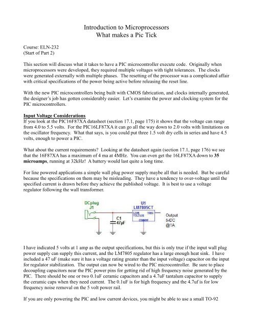
I have indicated 5 volts at 1 amp as the output specifications, but this is only true if the input wall plug<br />
power supply can supply this current, and the LM7805 regula<strong>to</strong>r has a large enough heat sink. I have<br />
included a 47 uF (make sure it has a voltage rating greater than the input voltage) capaci<strong>to</strong>r on the input<br />
for regula<strong>to</strong>r stabilization. The output can now be wired <strong>to</strong> the PIC microcontroller. Be sure <strong>to</strong> place<br />
decoupling capaci<strong>to</strong>rs near the PIC power pins for getting rid of high frequency noise generated by the<br />
PIC. There should be one or two 0.1uF ceramic capaci<strong>to</strong>rs and a 4.7uF tantalum capaci<strong>to</strong>r <strong>to</strong> supply<br />
the ceramic caps when they need current. The 0.1uF is for high frequency and the 4.7uf is for low<br />
frequency noise removal on the 5 volt power rail.<br />
If you are only powering the PIC and low current devices, you might be able <strong>to</strong> use a small TO-92
device, like the LM78L05, which can put out 100ma of current. Just make sure you include in the<br />
current calculation all loading on the pins of the PIC. Even though the PIC might only draw 5ma with<br />
no pins connected, you can supply up <strong>to</strong> 25ma per pin. That can add up fast when powering LEDs and<br />
driving low value resis<strong>to</strong>rs (never less than 200 ohms) in<strong>to</strong> the bases of transis<strong>to</strong>rs.<br />
If you are worried about efficiency, then the LM7805 is not a good choice. If you are drawing 500ma<br />
and the input voltage is 25volts, then the drop across the LM7805 is 25 – 5, or 20 volts. The output<br />
supplied wattage is 5 volts * 0.5 amps = 2.5 watts, where the dissipation in the regula<strong>to</strong>r is 20 volts *<br />
0.5 amps = 10 watts. That says the efficiency is 2.5 / (10 + 2.5) = 0.2 or 20%. Not very good<br />
considering that the 10 watts is just going up in heat and would require a large heat sink. So keep the<br />
input voltage as low as possible, making sure it is above the minimum required 7.0 volts. At 7.0 volts<br />
the dissipation in the regula<strong>to</strong>r would be 7 – 5 * 0.5 = 1 watt.<br />
PIC Reset Conditions<br />
Brown-Out-Reset (BOR)<br />
There is protection in the PIC for when the input voltage falls below the point at which the<br />
microcontroller may not function correctly. This is the brown-out reset (BOR). If the Vdd input<br />
voltage falls below 4 volts, and if the BOR is enabled (BOREN = 1), then the processor will be reset.<br />
When the voltage raises above 4 volts the BOR still stay enabled for 72 ms <strong>to</strong> ensure proper startup<br />
operation.<br />
Power On Reset (POR)<br />
Another reset that is in the PIC is the Power on Reset (POR) circuit. This is the main reset mechanism<br />
when the input voltage is being established. To make sure the POR functions properly the incoming<br />
Vdd voltage must raise faster than 0.05 V/ms. This is from the section 17.1 on page 175. So the power<br />
supply must be designed <strong>to</strong> accommodate this specification. When the input voltage has risen above<br />
1.2 <strong>to</strong> 1.7 volts (internally set), the POR generates a reset pulse. An internal timer <strong>makes</strong> sure that the<br />
controller stays in the reset condition for 72 ms, but it can be disabled with -PWRT set <strong>to</strong> 1 in the<br />
PCON register.<br />
Master Clear (-MCLR)<br />
Also involved in the powering up sequence is the negative active Master Clear (–MCLR) input line. To<br />
force an external reset, this line is pulled low, like with a pushbut<strong>to</strong>n connected <strong>to</strong> ground. The line<br />
should be pulled up with a resis<strong>to</strong>r and a capaci<strong>to</strong>r <strong>to</strong> ground, for noise. Microchip recommends that a<br />
resis<strong>to</strong>r greater than 1k ohm be put in line with the –MCLR pin. See figure 14-5 on page 148. I chose<br />
a 2.2k resis<strong>to</strong>r in the Lab. The pull up resis<strong>to</strong>r I use is a 4.7k with a 0.01uF ceramic capaci<strong>to</strong>r <strong>to</strong><br />
ground.<br />
Oscilla<strong>to</strong>r Start-up Timer (OST)<br />
The Oscilla<strong>to</strong>r Start-up Timer is active for 1024 oscilla<strong>to</strong>r clocks (OSC1 input), after PWRT concludes<br />
and helps <strong>to</strong> ensure the oscilla<strong>to</strong>r has stabilized. It is only activated for XT, LP and HS modes.<br />
Power Control Register (PCON)<br />
Section 2.2.2.8 on page 29 actually describes the individual bits, but section 14.10 on page 149<br />
describes the Power Control and Status Register, with the following page 150 showing the power on<br />
reset state of all the registers.
Oscilla<strong>to</strong>r Circuit<br />
Enough about reset circuits, lets get <strong>to</strong> where the microcontroller actually does something. The<br />
oscilla<strong>to</strong>r is the crank that sequences all the states in the PIC. The controls for the oscilla<strong>to</strong>r clock<br />
circuit can range from simple, a resis<strong>to</strong>r and capaci<strong>to</strong>r, <strong>to</strong> the complex with a crystal and stabilizing<br />
capaci<strong>to</strong>rs. You have <strong>to</strong> tell the microcontroller what type of circuit <strong>to</strong> expect by programming<br />
configuration bits <strong>to</strong> set modes. The following modes are available:<br />
LP Low-Power Crystal<br />
XT Crystal/Resona<strong>to</strong>r<br />
HS High-Speed Crystal/Resona<strong>to</strong>r<br />
RC Resis<strong>to</strong>r/capaci<strong>to</strong>r<br />
All the Oscilla<strong>to</strong>r types are described in Section 1.2 on page 145. It is basically cost verses accuracy.<br />
The RC network is cheap but it can drift and the initial accuracy is poor. To be able <strong>to</strong> time things well<br />
you have <strong>to</strong> use a crystal which can add cost. The crystal will allow you <strong>to</strong> drive the PIC <strong>to</strong> higher<br />
frequencies than the RC network. In the lab we will be using an RC network.<br />
On newer PICs ( like the PIC16F628A and PIC16F690 ) there are additional oscilla<strong>to</strong>r types:<br />
INTOSC Internal Precision 4 MHz Oscilla<strong>to</strong>r<br />
EC External Clock In<br />
Instruction Sequencing<br />
The oscilla<strong>to</strong>r sends a clock signal <strong>to</strong> the Timing Genera<strong>to</strong>r. The Timing Genera<strong>to</strong>r sequences the<br />
Instruction Decode and Control. This is the heart of the microcontroller.<br />
Figure 1: PIC Instruction Execution Timing Diagram<br />
As an instruction goes through execution, the next instruction is already being retrieved from the<br />
Program Memory. This overlap helps speed up execution, eliminating the wait for the instruction <strong>to</strong> be<br />
fetched from Program Memory. The key thing <strong>to</strong> remember from this timing diagram is it takes 4<br />
oscilla<strong>to</strong>r cycles <strong>to</strong> execute one instruction. We will use this timing information quite a lot in the<br />
future.<br />
Most instructions in the PIC execute in one instruction cycle, which is 4 clock cycles, (Refer <strong>to</strong> the<br />
datasheet’s table 15-2 on page 160) like the ADDWF, ANDWF, INCF and DECF. The ones that don’t<br />
are ones that change the program counter from incrementing <strong>to</strong> the next instruction. These would be<br />
like CALL, RETURN and GOTO.<br />
(End of Part 2)