Maxon OvenPak Flamerod and Igniter Setup - Megtec Systems
Maxon OvenPak Flamerod and Igniter Setup - Megtec Systems
Maxon OvenPak Flamerod and Igniter Setup - Megtec Systems

You also want an ePaper? Increase the reach of your titles
YUMPU automatically turns print PDFs into web optimized ePapers that Google loves.
Technical Bulletin<br />
<strong>Maxon</strong> <strong>OvenPak</strong><br />
<strong>Flamerod</strong> <strong>and</strong> <strong>Igniter</strong> <strong>Setup</strong><br />
The igniter position is also important. The tip of the<br />
igniter produces a high voltage spark that ignited<br />
the pilot gas when the burner starts. If the igniter is<br />
inserted to far, the tip may ground against the internal<br />
parts of the burner. This will prevent an ignition spark<br />
from being generated, resulting in the pilot gas not<br />
lighting <strong>and</strong> the burner shutting down. With the igniter<br />
pulled to far back from the required “Z” dimension,<br />
the spark gap may be to large to produce a strong<br />
enough spark to lithe the pilot gas or no spark may be<br />
produced at all, resulting in the burner locking out <strong>and</strong><br />
shutting down.<br />
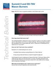
Figure 5. Relocate the flamerod<br />
ground wire from the site port screw<br />
to the burner casting bolts<br />
<strong>Flamerod</strong>s <strong>and</strong> igniters should be replaced annually.<br />
To improve flame rod signal strength, it may be helpful<br />
to move the signal ground wire from the connection<br />
at the burner site port to the casting of the burner as<br />
shown in figure 5.<br />
Please note: Local codes may require that a factory trained technician service your<br />
burner.<br />
UV Scanner P/N<br />
121231 For<br />
Burner<br />
EBC-2SP<br />
EBC-3SP<br />
EBC-4SP<br />
EBC-5SP<br />
EBC-6SP<br />
508<br />
515<br />
525<br />
535<br />
550<br />
<strong>Igniter</strong> P/N<br />
134031 “Z”<br />
Dimension<br />
4 3/4” (121)<br />
5 1/8” (130)<br />
4 3/4” (121)<br />
4 3/4” (121)<br />
4 3/4” (121)<br />
4 3/4” (121)<br />
5 1/8” (130)<br />
4 3/4” (121)<br />
4 3/4” (121)<br />
4 3/4” (121)<br />
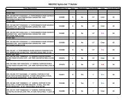
Chart 1. This chart is used for burners that<br />
use a UV-scanner instead of a flamerod.<br />
The “Z” dimension is still used to set the<br />
3