14. Design Guidelines for Grease Interceptors - Orange County ...
14. Design Guidelines for Grease Interceptors - Orange County ...
14. Design Guidelines for Grease Interceptors - Orange County ...

Create successful ePaper yourself
Turn your PDF publications into a flip-book with our unique Google optimized e-Paper software.
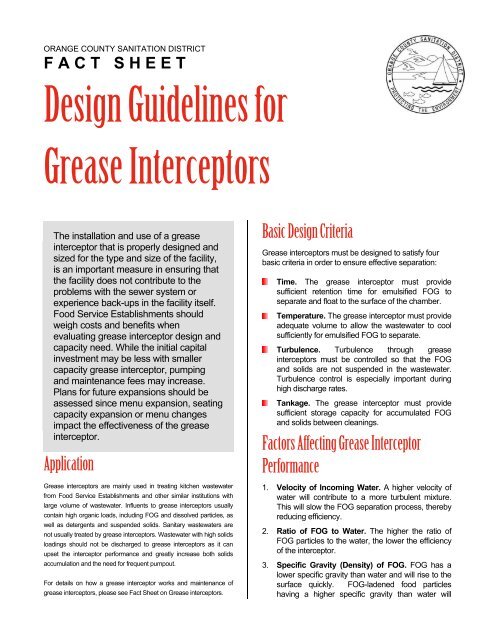
ORANGE COUNTY SANITATION DISTRICT<br />
F A C T S H E E T<br />
<strong>Design</strong> <strong>Guidelines</strong> <strong>for</strong><br />
<strong>Grease</strong> <strong>Interceptors</strong><br />
The installation and use of a grease<br />
interceptor that is properly designed and<br />
sized <strong>for</strong> the type and size of the facility,<br />
is an important measure in ensuring that<br />
the facility does not contribute to the<br />
problems with the sewer system or<br />
experience back-ups in the facility itself.<br />
Food Service Establishments should<br />
weigh costs and benefits when<br />
evaluating grease interceptor design and<br />
capacity need. While the initial capital<br />
investment may be less with smaller<br />
capacity grease interceptor, pumping<br />
and maintenance fees may increase.<br />
Plans <strong>for</strong> future expansions should be<br />
assessed since menu expansion, seating<br />
capacity expansion or menu changes<br />
impact the effectiveness of the grease<br />
interceptor.<br />
Application<br />
<strong>Grease</strong> interceptors are mainly used in treating kitchen wastewater<br />
from Food Service Establishments and other similar institutions with<br />
large volume of wastewater. Influents to grease interceptors usually<br />
contain high organic loads, including FOG and dissolved particles, as<br />
well as detergents and suspended solids. Sanitary wastewaters are<br />
not usually treated by grease interceptors. Wastewater with high solids<br />
loadings should not be discharged to grease interceptors as it can<br />
upset the interceptor per<strong>for</strong>mance and greatly increase both solids<br />
accumulation and the need <strong>for</strong> frequent pumpout.<br />
For details on how a grease interceptor works and maintenance of<br />
grease interceptors, please see Fact Sheet on <strong>Grease</strong> interceptors.<br />
Basic <strong>Design</strong> Criteria<br />
<strong>Grease</strong> interceptors must be designed to satisfy four<br />
basic criteria in order to ensure effective separation:<br />
Time. The grease interceptor must provide<br />
sufficient retention time <strong>for</strong> emulsified FOG to<br />
separate and float to the surface of the chamber.<br />
Temperature. The grease interceptor must provide<br />
adequate volume to allow the wastewater to cool<br />
sufficiently <strong>for</strong> emulsified FOG to separate.<br />
Turbulence. Turbulence through grease<br />
interceptors must be controlled so that the FOG<br />
and solids are not suspended in the wastewater.<br />
Turbulence control is especially important during<br />
high discharge rates.<br />
Tankage. The grease interceptor must provide<br />
sufficient storage capacity <strong>for</strong> accumulated FOG<br />
and solids between cleanings.<br />
Factors Affecting <strong>Grease</strong> Interceptor<br />
Per<strong>for</strong>mance<br />
1. Velocity of Incoming Water. A higher velocity of<br />
water will contribute to a more turbulent mixture.<br />
This will slow the FOG separation process, thereby<br />
reducing efficiency.<br />
2. Ratio of FOG to Water. The higher the ratio of<br />
FOG particles to the water, the lower the efficiency<br />
of the interceptor.<br />
3. Specific Gravity (Density) of FOG. FOG has a<br />
lower specific gravity than water and will rise to the<br />
surface quickly. FOG-ladened food particles<br />
having a higher specific gravity than water will
linger and accumulate at the bottom, eventually<br />
passing out of the interceptor.<br />
4. Possible Presence of Detergents in the System.<br />
<strong>Grease</strong>-cutting detergents will break the liquid<br />
grease into minute particles that can cause these<br />
liquids to pass through the interceptor.<br />
5. Percentage of Maximum Flow Capacity. If the<br />
maximum recommended flow is exceeded, the<br />
efficiency of the interceptor will decrease<br />
considerably.<br />
6. Location of <strong>Grease</strong> Interceptor. The interceptor<br />
should be located as close as possible to the<br />
source of FOG. Plumbing leading to the grease<br />
interceptor may become clogged if the wastewater<br />
cools prior to entering the grease interceptor.<br />
Sizing <strong>Grease</strong> <strong>Interceptors</strong><br />
<strong>Grease</strong> interceptors are designed and sized based on<br />
anticipated flow rates and organic load <strong>for</strong> maximum<br />
efficiency. The FOG Ordinance adopted by the <strong>Orange</strong><br />
<strong>County</strong> Sanitation District requires grease interceptor<br />
sizing to con<strong>for</strong>m to the Uni<strong>for</strong>m Plumbing Code. To<br />
calculate the size of a grease interceptor needed by a<br />
Food Service Establishment, refer to the following<br />
<strong>for</strong>mula taken from Appendix H of the Uni<strong>for</strong>m<br />
Plumbing Code:<br />
No. of<br />
Meals per<br />
peak hour 1<br />
x<br />
Waste<br />
Flow<br />
Rate 2<br />
x<br />
Retention<br />
Time 3<br />
1 Meals Served at Peak Hour<br />
2<br />
3<br />
4<br />
x<br />
Storage<br />
Factor 4 =<br />
To calculate the Waste Flow Rate, add all that<br />
apply:<br />
With dishwashing machine 6 gallons<br />
Without dishwashing machine 5 gallons<br />
Single-service kitchen<br />
2 gallons<br />
Food waste disposer<br />
1 gallon<br />
Retention Times:<br />
Commercial kitchen waste<br />
Dishwasher<br />
Single-service kitchen<br />
Single serving<br />
Storage Factors:<br />
Fully equipped commercial kitchen:<br />
8-hour operation 1<br />
16-hour operation 2<br />
24-hour operation 3<br />
Single-service kitchen 1.5<br />
2.5 hours<br />
1.5 hours<br />
Interceptor<br />
Size (Liquid<br />
Capacity)<br />
<strong>Grease</strong> Interceptor <strong>Design</strong> and<br />
Construction <strong>Guidelines</strong><br />
<strong>Grease</strong> interceptors shall be placed as close as<br />
practical to the fixture(s) being served. It shall be<br />
located where it is easily accessible at all times <strong>for</strong><br />
inspection, cleaning, and removal of accumulated<br />
grease.<br />
Minimum grease interceptor size shall be 750<br />
gallons; the maximum size shall be 1500 gallons<br />
unless authorized by OCSD in writing.<br />
<strong>Grease</strong> interceptors shall have two compartments.<br />
The inlet compartment shall be 2/3 of the total<br />
capacity of the interceptor and in all cases shall be<br />
longer than the maximum inside width of the<br />
interceptor. The outlet compartment shall have a<br />
minimum capacity of 1/3 of the total interceptor<br />
capacity. The liquid depth shall not be less than 2<br />
feet 6 inches nor more than 6 feet.<br />
Access to each grease interceptor shall be<br />
provided by a manhole over the inlet and a<br />
manhole over the outlet. There shall also be an<br />
access manhole <strong>for</strong> each 10 feet of length <strong>for</strong><br />
interceptors over 20 feet long. Manholes shall<br />
extend to grade, have a minimum size of 24 inches<br />
diameter or square opening, and shall have a<br />
gasketed cover at grade.<br />
The inlet and outlet shall have a baffle tee or similar<br />
flow device with a minimum cross sectional area<br />
equal to the required cross sectional area of the<br />
inlet. Each baffle shall extend from at least 4 inches<br />
above the liquid level to within at least 12 inches of<br />
the inside floor of the interceptor.<br />
Adequate partitions or baffles shall extend at least<br />
6 inches above the liquid level. Flow from inlet<br />
compartment to outlet compartment shall be<br />
through a quarter bend, or similar device equivalent<br />
in cross sectional area to the inlet into the<br />
interceptor, and shall extend down to within 12<br />
inches of the inside floor.<br />
The Inlet, outlet and main baffle shall have a free<br />
vent area equal to the required cross sectional area<br />
of the inlet pipe.<br />
For more details regarding construction, structural, and<br />
material requirements, consult Appendix H of the UPC.