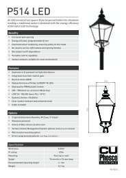
STADIUM MASTS - CU Phosco
STADIUM MASTS - CU Phosco
STADIUM MASTS - CU Phosco

Create successful ePaper yourself
Turn your PDF publications into a flip-book with our unique Google optimized e-Paper software.
2<br />
Allowance for seismic effects shall be made, if required, by<br />
means of the equation:-<br />
V = CW<br />
V = Nominal Seismic Force<br />
C = Seismic Co-efficient assumed to be 0.05, and<br />
W = Total Vertical Load<br />
For a limit state design, the nomimal seismic force shall be<br />
multiplied by partial load factors of 1.00 for the serviceability<br />
limit state and 1.40 for the ultimate limit state to obtain<br />
the design seismic forces. The design seismic force shall<br />
be applied successively longitudinally and transversely at<br />
the baseplate level. Each mast shall have a uniform steel<br />
flangeplate for bolting to the foundations together with a set<br />
of high tensile foundation bolts, a lower steel anchorplate<br />
and a removable steel template. The contractor shall be<br />
responsible for levelling the flangeplate on the prepared<br />
foundations and correctly aligning the mast. Exposed bolts<br />
and nuts shall be protected with ‘Denso’ tape or equal and<br />
approved, after lubrication with graphite filled silicon grease.<br />
Welding shall comply with the appropriate British Standards<br />
as listed in BS499. Details of the welding procedure shall be<br />
submitted in accordance with BS EN 1011.<br />
A copy of the calculations for the design of the masts showing<br />
clearly the grade of steel to be used shall be submitted for<br />
the approval of the engineer. Calculations shall take into<br />
account the weakening effect of the doorways.<br />
A base compartment shall be provided of adequate<br />
size to contain the winch mechanism equipment. The<br />
compartment shall have a vandal resistant, weatherproof<br />
access door with heavy-duty vandal resistant locks, suitable<br />
for identical pattern keys. A number of keys can be provided<br />
if required.A 16mm diameter corrosion resistant earth stud<br />
shall be fitted within the compartment. Adequate working<br />
space shall be available for operating the hoisting equipment<br />
at the foot of the mast.<br />
Protection of Steelwork against Corrosion<br />
Protection of surfaces shall be hot dipped galvanised to BS<br />
EN ISO 1461 for both internal and external faces. Painting<br />
of the mast is not required.<br />
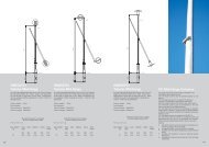
Winching Mechanism<br />
The maintenance cage shall be raised and lowered by a selfsustaining<br />
worm geared winch suitable for both manual and<br />
power driven operation and located at the foot of the mast.<br />
The winch shall be of double drum type which provides two<br />
completely separate suspension systems. The power tool<br />
shall be a four speed reversible tool incorporating a preset<br />
torque limiting device. Remote control switch shall be<br />
incorporated to allow the equipment to be operated from a<br />
distance of 5m. Arrangements shall be provided to support<br />
the power tool accurately and securely during operation.<br />
The winch and all hoisting equipment shall be adequate to<br />
allow for attaching hoist ropes to a maintenance cage or<br />
cradle which shall sustain a working load of 250 kgs. The<br />
hoisting mechanism shall comply with all appropriate safety<br />
regulations.<br />
The twin hoisting ropes shall be of stainless steel stranded<br />
wire running from the winch to the cage over pulleys made<br />
from non-corrodible metal at the top of the mast. The<br />
selection, provision and installatiom of the rope shall be in<br />
accordance with BSMA29. The pulley grooves shall be<br />
suitably protected against moisture, dirt and rust and fitted<br />
with close fitting guards to prevent derailment of the hoist<br />
rope. Self-lubricating pulley bearings shall be used. All<br />
vital parts of the hoisting mechanism shall be of stainless<br />
steel or other non-corrodible material to the approval of the<br />
engineer. Thimble type connections shall be used for ropes,<br />
wherever possible, alternatively, bulldog grips shall be used.<br />
Particular care shall be taken to ensure that the wire rope<br />
cannot abrade against any component.<br />
When the cage is in fully lowered position, at least to within<br />
1.3m of the base line, at least 4 turns of the hoisting rope<br />
shall be left on the winch drum to ensure that the securing<br />
arrangement on the drum does not take the full load when<br />
hoisting.<br />
The rope shall be as clearly visible as practicable during the<br />
hoisting operation. There shall be a clear indication near<br />
the winch to show when the cage has reached the design<br />
operating height. Details relating to lubrication shall be given<br />
on an engraved label fixed to, or adjacent to, the winch in a<br />
visible position.<br />
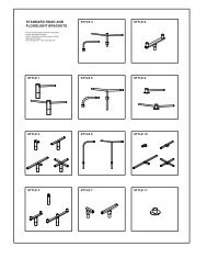
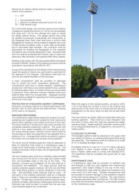
Floodlight Platform<br />
The floodlight platform shall be attached to the upper shaft<br />
by a bolted connection; no welding shall be permitted during<br />
site assembly. The headframe shall be inclined at an angle<br />
of 10° to facilitate floodlight aiming.<br />
Floodlights shall be in rows of 4, 6 or 8 to allow relamping<br />
from ladders in pairs; access ladders shall, if required,<br />
have a ‘Railok’ safety track to comply with BS5062/1973.<br />
The headframe shall be complete with guard rails for safe<br />
working.<br />
Maintenance Cage<br />
A maintenance cage shall be provided of sufficient size<br />
and strength to raise two men together with maintenance<br />
equipment, total weight 250kgs to the top of the mast.<br />
The maintenance cage shall be raised and lowered by the<br />
mast winch and wire ropes. Suitable arrangements shall<br />
be provided to prevent damage to the protective systems<br />
of the mast during raising and lowering. The cage shall be<br />
hot dipped galvanised after manufacture. The safe working<br />
load shall be prominently displayed in a permanent position<br />
on the maintenance cage.