Technical Guidelines Of An Ice Rink - IIHF
Technical Guidelines Of An Ice Rink - IIHF
Technical Guidelines Of An Ice Rink - IIHF

You also want an ePaper? Increase the reach of your titles
YUMPU automatically turns print PDFs into web optimized ePapers that Google loves.
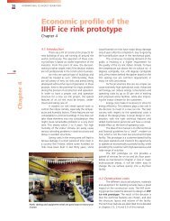
<strong>Technical</strong> guidelines<br />
of an ice rink<br />
Chapter 3<br />
3.1 General introduction<br />
<strong>Ice</strong> rink facilities share all the same concerns:<br />
energy usage, operating costs and indoor<br />
climate. <strong>Ice</strong> rink design and operation are totally<br />
unique and differ in many ways from standard<br />
buildings. Thermal conditions vary from -5 ºC on<br />
the ice surface to +10 ºC in the stand and +20 ºC<br />
in the public areas like dressing rooms and offices.<br />
High humidity of indoor air will bring on corroding<br />
problems with steel structures, decay in wooden<br />
structures and indoor air quality problems like<br />
fungi and mould growth etc. Obviously there are<br />
special needs to have technical building services<br />
to control the indoor climate and energy use of an<br />
ice-rink facility. Advanced technology can reduce<br />
energy consumption by even 50 % and thus decrease<br />
operating costs in existing and proposed<br />
ice rink facilities while improving the indoor climate.<br />
Energy costs and concern about the environment<br />
sets high demands for the technical<br />
solutions, without effective solutions the operational<br />
(energy, maintenance, replacement) costs<br />
will increase and short service life time of such a<br />
system is expected from the environmental point<br />
of view. Potentially a lot of savings can be made if<br />
the facilities are got operating as energy-efficiently<br />
as possible. This will require investment in energysaving<br />
technology and in raising energy awareness<br />
on the part of ice rink operators.<br />
The basic technical elements of a well-working<br />
facility are:<br />
• Insulated walls and ceiling<br />
• Efficient refrigeration plant<br />
• Mechanical ventilation<br />
• Efficient heating system<br />
• Air dehumidification<br />
1) Insulated walls and ceiling makes it possible<br />
to control the indoor climate regardless of<br />
the outdoor climate. In an open-air rink the<br />
operation is conditional on the weather (sun,<br />
rain, wind) and the running costs are high.<br />
Depending of the surroundings there might<br />
also be noise problems with the open-air rink –<br />
traffic noise may trouble the training or the<br />
slamming of the pucks against the boards may<br />
cause noise nuisance to the neighbourhood.<br />
Ceiling only construction helps to handle with<br />
sun and rain problems but may bring about<br />
maintenance problems in the form of ”indoor<br />
INTERNATIONAL ICE HOCKEY FEDERATION<br />
rain“: humid air will condensate on the cold<br />
inner surface of the ceiling and the dripping<br />
starts. The ceiling is cold because of the radiant<br />
heat transfer between the ice and the ceiling i.e.<br />
the ice cools down the inner surface of the ceiling.<br />
Though there are technical solutions to minimize<br />
the indoor rain problem (low emissive coatings)<br />
the ceiling only solution is still subjected<br />
to weather conditions and high running costs.<br />
2) The refrigeration plant is needed to make<br />
and maintain ice on the rink. Refrigeration<br />
plant includes the compressor(s), the condenser(s),<br />
the evaporator(s), and rink pipes. The heat<br />
from the rink is ”sucked“ by the compressor via<br />
the rink pipes and the evaporator and then<br />
released to the surrounding via the condenser.<br />
The heat from the condenser can be used to<br />
heat the ice rink facility and thus save considerably<br />
energy and money. Refrigeration plant is<br />
the main energy consumer in the ice rink facility.<br />
Compressors, pumps and fans needed in<br />
the refrigeration system are normally run by<br />
electricity and their electricity use may cover<br />
over 50 % of the total electricity use of an ice<br />
rink facility.<br />
3) Mechanical ventilation is necessary to be<br />
able to control the indoor air quality and<br />
thermal as well as humidity conditions inside<br />
the ice rink. Ventilation is needed both in<br />
the public spaces (dressing rooms, cafeteria,<br />
etc.) and in the hall. If you ever have visited a<br />
dressing room when the ventilation is off you<br />
will realize the necessity of the proper ventilation;<br />
the stink of the outfit of the hockey players<br />
is unthinkable. Inadequate ventilation will cause<br />
also health problems in the hall. To be energyefficient<br />
air renewal must be well controlled.<br />
This means that the ice rink enclosure should<br />
be airtight so that there are no uncontrollable<br />
air infiltration through openings (doors etc.)<br />
and roof-to-wall joints. Air infiltration will increase<br />
energy consumption during the warm<br />
and humid seasons related to refrigeration and<br />
dehumidification and during the cold seasons<br />
this is associated with space heating. This leads<br />
us to the fourth basic demand: the ice rink<br />
facility must be heated. Unheated ice rink is<br />
freezing cold even in warm climates and<br />
humidity control of the air becomes difficult.<br />
Chapter 3<br />
15
16<br />
Chapter 3<br />
INTERNATIONAL ICE HOCKEY FEDERATION<br />
<strong>Rink</strong> piping<br />
Cooling coil<br />
Coolant<br />
pump<br />
Refrigeration<br />
unit<br />
Figure 1. Refrigeration plant, indirect cooling system.<br />
Insulated exterior envelope<br />
• Enables to build an ice rink anywhere in<br />
the world<br />
• Air tight envelope to avoid moisture<br />
problems<br />
Heat recovery<br />
Liquid<br />
pump<br />
4) Ventilation offers also a means to heat the ice<br />
rink. Heating the ice rink with air necessitates<br />
the use of re-circulated air and that the ventilation<br />
unit is equipped with heating coil(s).<br />
Remarkable energy-savings can be achieved<br />
when using waste heat of the refrigeration<br />
process to warm up the air.<br />
5) The dehumidification plant is needed in wellworking<br />
facility to dry the rink air. Excess moisture<br />
in indoor air will cause corrosion of metal<br />
structures, rotting of wooden structures, fungi<br />
and mould growth, increased energy consumption<br />
and ice quality problems.<br />
Heating<br />
• Maintains acceptable thermal<br />
conditions<br />
• Use heat recovered from the<br />
refrigeration plant (condenser heat)<br />
as much as possible<br />
Mechanical ventilation<br />
• Provides good indoor<br />
air conditions<br />
• Demand-controlled ventilation<br />
saves money and energy<br />
Figure 2. The construction, plant system and operation define energy consumption of an ice rink.<br />
Energy consumption is in the key role when<br />
speaking of the life cycle costs and above all the<br />
environmental load of the facility during its life<br />
cycle. The key to the effective utilization of the<br />
energy resources in new as well as in retrofit and<br />
refurbishment projects is in the consciousness of<br />
the energy-sinks and the various parameters affecting<br />
the energy consumption.<br />
The construction, plant system and operation<br />
define the energy consumption of an ice rink.<br />
The construction characteristics are the heat and<br />
moisture transfer properties of the roof and walls,<br />
as well as air infiltration through cracks and openings<br />
in the building envelope. The structure of the<br />
floor is also important from the energy point of<br />
view. Plant characteristics include the refrigeration,<br />
ventilation, dehumidification, heating, lighting and<br />
ice maintenance systems. The operational characteristics<br />
are the length of the skating season, air<br />
temperature and humidity, ice temperature, supply<br />
air temperature and fresh air intake of the air-handling<br />
unit as well as the control- and adjustment<br />
parameters of the appliances. Figure 3 shows the<br />
energy spectrums of typical training rinks and<br />
figure 4 illustrates the energy flows of a typical<br />
small ice rink.<br />
Dehumidification<br />
• Dehumidification prevents moisture<br />
problems (fog, soft ice, damages to<br />
the building)<br />
• Dry ventilation air before entering the<br />
building<br />
Refrigeration plant<br />
• Needed to make and maintain ice<br />
• Pay attention to the energy<br />
efficiency of the plant (high COP)
Electricity Heat<br />
� Compressor 47%<br />
� Brine pumps & condenser fans 14%<br />
� <strong>Ice</strong>-surface lighting 12%<br />
� Lighting 2%<br />
� HVAC appliances (pumps, fans, controllers, etc.) 9%<br />
� Other consumption<br />
� (cafe, cleaning, outdoor lights, etc.) 12%<br />
� Dehumidification 4%<br />
In an ideal situation the heating demand of<br />
the ice rink is totally covered with recovered heat<br />
from the refrigeration process. In practice extra<br />
heat is still needed to cover the needs of hot tap<br />
water and heating peaks. Moreover a backup<br />
Electricity<br />
900 MWh<br />
Heat 200 MWh<br />
Surplus heat<br />
1000 MWh<br />
Recovered<br />
heat 800 MWh<br />
� Space heating 67%<br />
� Warm water 17%<br />
� Melting the snow 16%<br />
Figure 3. Main electricity and heat consumption components of a typical training facility.<br />
Figure 4. While producing cold, the ”ice plant“ provides heat that can be utilized in space heating and hot<br />
water production. Still there is a great deal of extra heat that could be made good use of for example in a<br />
nearby indoor swimming pool.<br />
INTERNATIONAL ICE HOCKEY FEDERATION<br />
heating system is needed to meet the heating<br />
demands when the compressors are not running<br />
for example during dry floor events (concerts,<br />
shows, meetings, etc.).<br />
Energy losses<br />
600 MWh<br />
Cooling energy<br />
1300 MWh<br />
Chapter 3<br />
17
18<br />
Chapter 3<br />
INTERNATIONAL ICE HOCKEY FEDERATION<br />
3.2 Sizing the ice rinks<br />
There are several ways to classify ice sport<br />
venues and in this manual the definition will be<br />
done on the basis of fixed seating capacity, size of<br />
the food service supply and multi-purpose possibilities.<br />
There fore the sizing of the ice sport venues are<br />
divided into three categories as follow:<br />
• Small ice rinks with seating capacity up to 2000<br />
• Medium size ice arenas between 2000 and<br />
6000 seats with some multi-purpose features<br />
• Modern multi-purpose ice arenas with over<br />
6000 fixed seats with a wide scale catering offer<br />
and many possibilities for multi-purpose use<br />
Small ice rinks can be done without any<br />
fixed seating or any foodservice capability, although<br />
the modern small ice rinks are without exception<br />
also concentrating on getting additional revenues<br />
through special hospitality programs.<br />
Figure 5. Small ice rink, capacity less than 2000 seats.<br />
Figure 6. Multi-purpose arena, capacity over 8000 seats.<br />
It is strongly than recommended that the<br />
first studies for a new ice rink will be done on a so<br />
called modular base, which allows in later years<br />
possibilities for optional enlargements. These later<br />
modifications could be like an additional ice pad,<br />
enlarged spectator stand or a restaurant.<br />
In order to make the optional features possible<br />
for later realization, the designer team should<br />
take into consideration some technical features like:<br />
• Sizing of refrigeration unit<br />
• Main structural support system, where for example<br />
the columns and foundations on one side<br />
of the building are from beginning planned to<br />
take later on extra load from additional structures<br />
• Envelope structure, like external walls, should<br />
be at least partly removable<br />
In this manual we are only concentrating<br />
on a small ice rink by defining an <strong>IIHF</strong> prototype<br />
ice rink with about 500 fixed seating and a small<br />
restaurant.<br />
3.3 <strong>IIHF</strong> prototype definition<br />
Minimum required space, <strong>IIHF</strong> prototype ice<br />
rink<br />
In a small ice rink there is a minimum space<br />
needed for following use:<br />
• at least one standard <strong>IIHF</strong> ice pad, size of 30 m x<br />
60 m surrounded by a dasher board and glass<br />
protection with 1,5 m minimum space outside<br />
of the dasher board<br />
• four dressing rooms incl. toilets, showers and<br />
lockers for personal items<br />
• two coach rooms<br />
• referees and linesmen dressing room incl. toilet<br />
and shower<br />
• two drying rooms<br />
• entrance hall, ticketing<br />
• medical room<br />
• equipment service room (skate sharpening, stick<br />
storage etc.)<br />
• storage space<br />
• technical room for mechanical and electrical<br />
system<br />
• tribune for 500 spectators<br />
• public toilets<br />
• small restaurant
Required minimum space for each type of room in a <strong>IIHF</strong> prototype ice rink:<br />
3.4 Materials and structural systems<br />
for an ice rink<br />
First of all, most important to know about<br />
ice rinks and ice arenas are to understand their<br />
different features compare to any other kind of<br />
buildings. These special features are due to:<br />
• High inside temperature differences in same<br />
indoor climate from -4 °C to +24 °C, where at<br />
the same time these internal climate zones must<br />
be controlled and stay stable<br />
• Differences in indoor climate also cause humidity<br />
problems that must be under control<br />
• Air tightness is more important feature of the<br />
building envelope than thermal insulation<br />
• Large glazing of the facade should be avoided<br />
due to energy costs by operating the facility and<br />
the most optimised ice rink could be done by a<br />
fully closed casing<br />
However, like in all other kind of buildings,<br />
there are structural possibilities for almost all kinds<br />
of systems with numerous materials. Main structural<br />
systems used for the ice rinks and arenas are<br />
normally:<br />
• Arched girders<br />
• Grids with mast columns<br />
• Frameworks<br />
Figure 7. Structural systems.<br />
INTERNATIONAL ICE HOCKEY FEDERATION<br />
Room Surface area Typical surface texture<br />
nett Flooring (water proof)* Ceiling Wall finishing<br />
Main hall - Dasher board with surrounding 2100 m 2 Painted concrete slab Metal sheet of roofing Outside walls, painted<br />
Small restaurant 132 m 2 wooden surfacing Wood lining Painted brick walls or concrete<br />
Players dressing room (4 x) 30 m 2 8 mm rubber surfacing * Wood lining Painted brick walls or concrete<br />
Referees and lines-men room 18 m 2 8 mm rubber surfacing * Wood lining Painted brick walls or concrete<br />
Drying room (2 x) 4 m 2 Painted concrete slab Concrete (underneath) Painted brick walls or concrete<br />
Medical room 15 m 2 8 mm rubber surfacing * Plasterboard Painted brick walls or concrete<br />
Equipment service room 8 m 2 Painted concrete slab Concrete (underneath) Painted brick walls or concrete<br />
<strong>Technical</strong> room 50 m 2 Painted concrete slab * Metal sheet of roofing Plasterboard<br />
<strong>Ice</strong> resurfacing machine 50 m 2 Painted concrete slab * Metal sheet of roofing Painted brick walls or concrete<br />
Coat-rack for public ice skating 20 m 2 2 mm plastic surfacing Metal sheet of roofing Plasterboard<br />
Dressing rooms for public ice skating (2 x) 10 m 2 8 mm rubber surfacing * Wood lining Painted brick walls or concrete<br />
Entrance hall, ticketing 70 m 2 ceramic tile floor Plasterboard Plasterboard<br />
<strong>Of</strong>fice 20 m 2 2 mm plastic surfacing Plasterboard Plasterboard<br />
This requires a total building surface area of 3700 m 2 .<br />
Mast-supported grid Rigid frame<br />
Arched frame Mast-supported grid<br />
Arched girder Cable supporter<br />
Chapter 3<br />
19
20<br />
Chapter 3<br />
INTERNATIONAL ICE HOCKEY FEDERATION<br />
Below you will find existing examples of<br />
small rinks with these different roof structures.<br />
Hartwall Jaffa Arena Training <strong>Rink</strong><br />
Eura, Finland<br />
Facts<br />
• Building year: 2000<br />
• Building area: 2520 m 2 (70 x 26 m)<br />
• <strong>Ice</strong> pad size: 58 x 28 m<br />
• Seats: 400<br />
• Skating season: 8 months (August–March)<br />
• <strong>Ice</strong> charge: 44–72 €/hour<br />
• Personnel: 2<br />
• Heating consumption: 710 MWh/year<br />
• Electricity consumption: 710 MWh/year<br />
• Water consumption: 2200 m 3 /year<br />
Layout<br />
The layout of the rink is simple, the stand<br />
and the players boxes are on the opposite sides of<br />
the rink, four dressing rooms are at the end of the<br />
hall. On top of the dressing rooms there are office<br />
rooms, lecture room and cafeteria. The space under<br />
the spectator seat is used as storage. <strong>Technical</strong><br />
room is placed in a separate container outside of<br />
the rink.<br />
Structures<br />
The rigid frame structure of the rink is<br />
made of glue laminated timber. The roofing and<br />
the walls are made of polyurethane elements. To<br />
improve the energy efficiency of the rink the air<br />
tight polyurethane elements are equipped with<br />
low emissivity coating laminated on the indoor<br />
surface of the elements. The elements have also<br />
acoustic dressing which improves the acoustic<br />
atmosphere of the rink. The facades are made of<br />
bricks and profiled metal sheets.
Training <strong>Rink</strong><br />
Hämeenkyrö, Finland<br />
Facts<br />
• Building year: 1997<br />
• Building area: 2590 m 2 (68 x 38 m)<br />
• <strong>Ice</strong> pad size: 58 x 28 m<br />
• Seats: 600<br />
INTERNATIONAL ICE HOCKEY FEDERATION<br />
• Skating season: 8.5 months<br />
• <strong>Ice</strong> charge: 59–104 € / hour<br />
• Personnel: 1–2<br />
• Heating consumption: 395 MWh/year<br />
• Electricity consumption: 490 MWh year<br />
• Water consumption: 1100 m 3 /year Layout<br />
The four dressing rooms with showers are<br />
under the seat along the long side of the hall. At<br />
the other end of the hall there is a cafeteria and a<br />
training room.<br />
Structures<br />
The arched girder structure of the rink is<br />
made of glue laminated timber. The roofing and<br />
the walls are made of polyurethane elements. To<br />
improve the energy efficiency of the rink the air<br />
tight polyurethane elements are equipped with<br />
low emissivity coating laminated on the indoor<br />
surface of the elements. The elements have also<br />
acoustic dressing which improves the acoustic atmosphere<br />
of the rink. The facades are made of<br />
profiled metal sheets, clapboard and lime bricks.<br />
Chapter 3<br />
21
22<br />
Chapter 3<br />
INTERNATIONAL ICE HOCKEY FEDERATION<br />
Monrepos Arena Training <strong>Rink</strong><br />
Savonlinna, Finland<br />
Facts<br />
• Building year: 1999<br />
• Building area: 2420 m 2 (67 x 36 m)<br />
• <strong>Ice</strong> pad size: 58 x 28 m<br />
• Seats: 400<br />
• Skating season: 12 months<br />
• <strong>Ice</strong> charge: – summer 59– 83 € / hour<br />
– other time 38–73 € / hour<br />
• Personnel: 3<br />
• Heating consumption: 760 MWh/year<br />
(76 m 3 oil)<br />
• Electricity consumption: 720 MWh/year<br />
• Water consumption: 3500 m 3 /year
Layout<br />
Four of the six dressing rooms with showers<br />
are under the seat along the long side of the hall<br />
and the other two dressing rooms at the end of<br />
the hall. On top of these two dressing rooms there<br />
are office rooms, lecture room, cafeteria, TV stand<br />
and air conditioner. <strong>Technical</strong> room (refrigeration<br />
unit) is placed in a separate container outside of<br />
the rink.<br />
Structures<br />
The mast-supported grid constructure of<br />
the rink is made of glue laminated timber. The<br />
roofing and the walls are made of polyurethane<br />
elements. To improve the energy efficiency of<br />
the rink the air tight polyurethane elements are<br />
equipped with low emissivity coating laminated<br />
on the indoor surface of the elements. The elements<br />
have also acoustic dressing which improves<br />
the acoustic atmosphere of the rink. The facades<br />
are made of profiled metal sheets.<br />
In this manual we will concentrate on a<br />
structural system of a grid supported by columns<br />
and the materials for this structural system can be<br />
divided into four main categories:<br />
• Steel structures<br />
• Wood structures<br />
• Reinforced concrete structures<br />
• Mix material structures of steel, wood and/or<br />
concrete<br />
Materials and structural system<br />
Steel support<br />
+ long span length<br />
+ global availability<br />
+ pre-fab system<br />
+ cost<br />
- corroding<br />
- fire protection<br />
- maintenance<br />
Wood support<br />
+ long span length<br />
+ non corroding<br />
+ pre-fab system<br />
+ fire protection<br />
- global availability<br />
- cost<br />
- maintenance<br />
- decaying<br />
Figure 5. Material features of main supporters.<br />
If the idea of a modular system is found<br />
possible and reasonable, the best flexibility in use<br />
with either steel or wood frame structures. However<br />
through careful and skilled engineering the<br />
later changes of the supporting structure are also<br />
possible with all other materials and systems.<br />
In the design phase all structural capabilities<br />
of the building for later enlargement should<br />
be defined in combination with the size of the<br />
plot, traffic situation and possible changes in the<br />
surrounding.<br />
By becoming aware of the special features<br />
of an ice rink, there are several possibilities to<br />
optimise the ice rink construction costs that will<br />
also lower the later operational costs.<br />
Reinforced concrete<br />
+ global availability<br />
+ non corroding<br />
+ pre-fab system<br />
+ fire protection<br />
- cost<br />
- beam span length<br />
- acoustic feature<br />
- flexibility in use<br />
INTERNATIONAL ICE HOCKEY FEDERATION<br />
3.4.1 Structural system as used in the<br />
<strong>IIHF</strong> prototype<br />
The roof structure consists of steel trusses<br />
supported each by two concrete columns. At<br />
support points the bottom boom of the truss bears<br />
on an elastomeric bearing pad bolted to the supporting<br />
concrete column. The whole roof structure<br />
of steel (see roofing 3.3.2) is floating on top of the<br />
concrete framework. The concrete columns are<br />
mounted ridged to the concrete foundations.<br />
Regarding to the region of the planned<br />
new ice rink, the horizontal loads of the roof<br />
structure, like snow are highly affecting when<br />
choosing the most economical structural system.<br />
If the snow loads are not remarkable, the steel<br />
trusses could easily cost efficiently be spanned<br />
over the spectator stand and the dashed board,<br />
using the span length like 40 to 45 meters and<br />
concrete column raster of 6 to 8 meters. A minimum<br />
free space between the ice surface and the<br />
bottom of steel trusses should be at least 6 meters.<br />
In order to avoid serious problems with<br />
humidity, like corrosion etc. the mechanical and<br />
electrical plant must be equipped with a dehumidification<br />
system.<br />
3.4.2 Envelope, roofing<br />
The main function of an ice rink envelope<br />
is air tightness and not particularly thermal insulation.<br />
The envelope structure can be done most efficiently<br />
to fulfil only that one main characteristic.<br />
Mix material<br />
combinations<br />
+ long span length<br />
+ fire protection<br />
+ pre-fab system<br />
+ cost<br />
- corroding<br />
- decaying<br />
- cost<br />
- maintenance<br />
Most used roofing structures consist of following<br />
layers:<br />
• Profiled, load bearing steels sheets<br />
• Vapour barrier<br />
• Thermal insulation (10 cm to 15 cm rock wool)<br />
• Water insulation<br />
Figure 6. Typical roof structure.<br />
Cladding, external<br />
metal sheet<br />
Thermal insulation<br />
Vapour barrier<br />
Load bearing metal sheet<br />
Chapter 3<br />
23
24<br />
Chapter 3<br />
INTERNATIONAL ICE HOCKEY FEDERATION<br />
3.4.3 Envelope, walls<br />
The outside wall structure of an ice rink is<br />
commonly also based on the idea of air tightness<br />
and the simplest walling is done by using different<br />
metal sheet panels. These panels are simple, prefabricated<br />
sandwich elements, that have inside<br />
a core of thermal insulation of rock wool or<br />
polyurethane and both sides covered with metal<br />
sheets.<br />
These panels also allow later changes of<br />
the envelope very easily and with rather low additional<br />
costs.<br />
These metal sheet panels are delivered<br />
with a long range of length up to 8 meters each,<br />
in large scale of different colours and surface<br />
treatment. A harmful aspect by using these metal<br />
sheet panels is a rather poor resistance against<br />
mechanical exertion like hits of the hockey pucks<br />
inside or vandalism.<br />
Therefore it is recommended to use in a<br />
lower partition of outside wall sandwich elements<br />
of concrete and replace them over 2.5 meter<br />
height with metal sheet panels.<br />
Figure 8. Typical wall structure.<br />
3.4.4 <strong>Ice</strong> pad structure<br />
Perhaps the most special structure in an ice<br />
rink is the ice pad. The ice pad consists of ground<br />
layers below the pad, thermal insulation, piping<br />
and pad itself. New technologies have made possible<br />
the use of new materials and technical solutions<br />
in these structures, where at the same time<br />
the energy efficiency and construction costs could<br />
be optimised.<br />
The most common surfacing materials is:<br />
• Concrete<br />
However sand surface is cheapest and fairly<br />
energy economical because of the good heat<br />
transfer characteristics but the usability is limited<br />
to ice sports. Asphalt surfaces are suitable for<br />
some special needs, for example in the case that<br />
the facility is used for tennis off the ice sport<br />
season. Asphalt is cheaper than concrete but the<br />
refrigeration energy requirement is higher.<br />
metal sheet panel 100 mm<br />
prefab concrete sandwich concrete unit<br />
30 mm<br />
Cooling pipes<br />
Heating pipes<br />
for ground<br />
frost protection<br />
500 mm<br />
Figure 9. Typical ice pad construction.<br />
<strong>Ice</strong><br />
30 mm<br />
Concrete<br />
120 mm<br />
Insulation<br />
100 mm<br />
Gravel fill<br />
500 mm<br />
Foundation soil<br />
500 mm<br />
<strong>Rink</strong> pipe material (plastic/metal) and space<br />
sizing are questions of optimisation of investments<br />
vs. energy. The cooling pipes are mounted quite<br />
near the surface, in a concrete slab the mounting<br />
depth is normally 20–30 mm and the mounting<br />
space between the pipes is 75–125 mm. The rink<br />
pipes are connected to the distribution and collection<br />
mains, which are laid along the rink short<br />
or long side outside the rink. <strong>Rink</strong> pipes are laid in<br />
U-shape and they are mounted to the surfacing<br />
layer by simply binding the pipes directly to the<br />
concrete reinforcement or to special rails.
U-shaped rink piping<br />
Distribution and collection<br />
mains along the short side<br />
Figure 10. Collectors along the short side of the ice rink.<br />
Figure 12. Plastic rink piping connections to the distribution<br />
and the collection mains (thermally insulated).<br />
3.5 Mechanical and electrical plant<br />
The effective utilization of the energy resources<br />
has become an important aspect in the<br />
design of new facilities. There are many different<br />
energy conservation measures that can be incorporated<br />
in the planning stage. In planning the<br />
hardware configuration and construction of an<br />
ice rink, it is important to consider the types of<br />
activities, special requirements and interest of the<br />
various user groups in question. Table 1 summarise<br />
the main indoor air design values, which can<br />
be used in designing technical building services. It<br />
is important to set these values already in the<br />
pre-design stage in order to control the demands.<br />
U-shaped rink piping<br />
Distribution and collection<br />
mains along the long side<br />
INTERNATIONAL ICE HOCKEY FEDERATION<br />
Figure 11. Collectors along the long side of the ice rink.<br />
Action Air temperature of <strong>Ice</strong> temperature, ºC Max. relative humidity Min. fresh air intake<br />
the rink space ºC of the rink space (%) l/s/occupant<br />
<strong>Rink</strong> (at 1.5 m Tribune<br />
height) (operative)<br />
Hockey<br />
- game +6 +10.+15 -5 70 4...8 / spectator<br />
- training +6 +6. +15 -3 70 12 / player<br />
Figure<br />
- competition +12 +10.+15 -4 70 4...8 / spectator<br />
- training +6 +6. +15 -3 70 12 / skater<br />
Other +18 +18 - - 8 / person<br />
Indoor air design values for small ice rink (rink space).<br />
3.5.1 Refrigeration plant<br />
Refrigeration plant is fundamental to the<br />
ice-rink facility. Much used, but true, phrase is that<br />
the refrigeration unit is the heart of the ice rink.<br />
Almost all of the energy-flows are connected to<br />
the refrigeration process in one way or another. It<br />
is quite normal that the electricity consumption of<br />
the refrigeration system accounts for over 50 % of<br />
the total electricity consumption and the heat loss<br />
of the ice can be over 60 % of the total heating<br />
demand of an ice rink.<br />
In the design stage, when choosing the refrigeration<br />
unit one has to consider the economics,<br />
energy usage, environment, operation, maintenance<br />
and safety.<br />
The design of the refrigeration plant can be<br />
either so-called direct or indirect system. In a direct<br />
system the rink piping works as the evaporator,<br />
whereas an indirect system is comprised of separate<br />
evaporator (heat exchanger) and the ice pad<br />
is indirectly cooled by special coolant in closed<br />
circulation loop. The energy efficiency of the direct<br />
system is in general better than the efficiency of<br />
the indirect system. On the other hand the first<br />
cost of the direct system is higher than that of the<br />
indirect system. Moreover indirect systems can’t<br />
be used with for example ammonia in several<br />
countries because of health risks in the case of<br />
refrigerant leaks. Table 2 summarises the advantages<br />
and disadvantages of the different systems.<br />
Chapter 3<br />
25
26<br />
Chapter 3<br />
INTERNATIONAL ICE HOCKEY FEDERATION<br />
Pad structure<br />
• ice thickness<br />
• slab thickness and thermal<br />
properties<br />
• pipe material and sizing<br />
• cooling liquid properties<br />
• frost insulation<br />
• frost protection heating<br />
Direct system Indirect system<br />
+ Energy efficiency + Use of factory made refrigeration units<br />
+ Simple + Small refrigerant filling (environmentally positive)<br />
+ Suitable to any refrigerant<br />
- Not possible with certain refrigerants (ammonia) - Lower energy efficiency than with direct system<br />
- Installation costs<br />
- Need of professional skills in design and in installing<br />
Features of direct and indirect refrigeration plant.<br />
In most cases the refrigeration plant comprises<br />
the refrigerant circuit refrigerates an indirect<br />
system i.e. the floor by a closed brine circuit rather<br />
than directly. The refrigerant used in the compressor<br />
loop should be environmentally accepted, for<br />
example natural substances like ammonia (NH 3)<br />
and carbon dioxide (CO 2) or HFC refrigerants such<br />
as R134a, R404A and R407A. The tendency is to<br />
favour in natural substances of HFCs. In choosing<br />
the refrigerant the country-specific regulations must<br />
be taken into account. The operational aspect is<br />
to equip the compressor with reasonable automation,<br />
which enables demand-controlled running<br />
of the system. In addition, the safety factors should<br />
be incorporated in the design of the machine<br />
room.<br />
From the energy point of view it is a matter<br />
of course that the compressor unit should be as<br />
efficient as possible, not only in the design point<br />
but also under part-load conditions.<br />
Indoor climate<br />
• air temperature<br />
• ceiling temperature and material<br />
• air humidity<br />
• ice temperature<br />
Automation<br />
Figure 12. Refrigeration unit and related energy flows.<br />
QCO<br />
Condenser<br />
Compressor<br />
Evaporator<br />
QEV<br />
Refrigeration unit<br />
• evaporating and condensing<br />
temperatures<br />
• efficiency<br />
• compressor type<br />
• sizing<br />
• refrigerant<br />
Q EL<br />
When estimating the energy economy of<br />
the system it is essential to focus on the entire<br />
system and not only on one component alone.<br />
The refrigeration plant is an integral part of the ice<br />
rink, Figure 12.<br />
Design and dimensioning aspects<br />
The refrigeration plant is dimensioned according<br />
to cooling load and the required evaporation<br />
and condenser temperatures. For a standard<br />
single ice rink approximately 300–350 kW of refrigeration<br />
capacity is adequate.<br />
The refrigeration capacity is normally sized<br />
according to the heat loads during the ice making<br />
process. The dimensioning cooling load during<br />
the freezing period is comprised of the following<br />
components:<br />
• Cooling the ice pad construction down to the<br />
operating temperature in required time. Needed<br />
cooling capacity depends on the temperature of<br />
the structures at the beginning of the freezing and<br />
the required freezing time (normally 48 hours).<br />
• Cooling the temperature of the flooded water<br />
to the freezing temperature (0 ºC) and then<br />
freezing the water to form the ice and to cool<br />
the temperature of the ice to the operating temperature.<br />
The freezing capacity depends on the<br />
temperature of the water, the operating temperature<br />
of the ice and the required freezing<br />
time (48 hours).<br />
• Heat radiation between the rink surface and the<br />
surrounding surfaces. Cooling capacity depends<br />
on the surface temperatures during the freezing<br />
period.<br />
• Convective heat load between the rink surface<br />
and the air. Cooling capacity depends on the air<br />
and rink surface temperatures both the air<br />
stream velocity along the rink surface during the<br />
freezing period.<br />
• Latent heat of the condensing water vapour<br />
from the air to the rink surface. Cooling capacity
depends on the air humidity (water vapour pressure)<br />
and the surface temperature of the rink<br />
during the freezing period.<br />
• Radiation heat load on rink surface during the<br />
freezing period (lights etc.).<br />
• Pump-work of the coolant pump.<br />
3.5.1.1 Refrigeration unit<br />
Refrigeration unit is comprised of many<br />
components: compressor(s), evaporator, condenser,<br />
and expansion valve and control system.<br />
The function of the compressor is to keep<br />
the pressure and temperature in the evaporator<br />
low enough for the liquid refrigerant to boil off<br />
at a temperature below that of the medium surrounding<br />
the evaporator so that heat is absorbed.<br />
In the compressor the vapour is raised to high<br />
pressure and high enough temperature to be<br />
above that of the cooling medium so that heat<br />
can be rejected in the condenser. After the condensation<br />
the liquid refrigerant is throttled in the<br />
expansion valve back to the pressure of the evaporator.<br />
In other words the compressor ”pumps“<br />
<strong>Ice</strong> pad Evaporator<br />
Cooling pipes<br />
Ground frost protection<br />
Dehumidification<br />
Figure 13. Two screw compressors.<br />
Outdoor cooling coil<br />
Refrigeration unit<br />
Compressor<br />
cooling<br />
Condenser<br />
INTERNATIONAL ICE HOCKEY FEDERATION<br />
Ventilation unit<br />
Floor heater<br />
Hot water storage<br />
Figure 14. Refrigeration plant with heat recovery: preheating of hot water, floor heating and air heating.<br />
Chapter 3<br />
27
28<br />
Chapter 3<br />
INTERNATIONAL ICE HOCKEY FEDERATION<br />
heat from the rink to the surroundings, which is<br />
similar process to a normal fridge.<br />
There are different types of refrigeration<br />
compressors on the market of which reciprocating<br />
compressors and screw compressors are<br />
the most common types. In most cases the compressors<br />
are electric driven. The refrigeration unit<br />
consists normally of at least 2 compressors to<br />
guarantee flexible and economical use of the unit.<br />
3.5.1.2 <strong>Ice</strong> pad<br />
<strong>An</strong>other interesting aspect in the energychain<br />
is the heat resistance between the ice and<br />
the brine, which has effect on the energy consumption.<br />
The underlying energy-thinking in the<br />
heat resistance is, the bigger the resistance is the<br />
lower the brine and evaporation temperature of<br />
the compressor should be in order to produce the<br />
same cooling effect as with smaller resistance. The<br />
lower the evaporation temperature is the bigger<br />
the power need of the compressor. Heat resistance<br />
consists of five different parameters: (1) the<br />
so-called surface resistance of the ice surface,<br />
which is a combination of ceiling radiation and<br />
convection as discussed earlier. (2) Heat resistance<br />
of the ice, mainly dependent on the ice thickness.<br />
(3) Likewise the ice, the concrete slab or any other<br />
surfacing material constitutes heat resistance<br />
based on the thickness of the layer and the<br />
heat conductivity of the material involved. (4) Pipe<br />
material and pipe spacing in the floor. (5) Surface<br />
resistance between the pipe and fluid.<br />
The function of secondary coolants is to<br />
transfer heat from the rink to the evaporator in<br />
the refrigeration unit. The profile of the perfect<br />
coolant would be: environmentally friendly, nontoxic,<br />
low pumping costs, high efficiency (good<br />
heat transfer characteristics), and non-corrosive,<br />
cheap and practical. Quite a variety of coolants<br />
are in use, table 2 summarize the most common<br />
of them.<br />
In the construction of the ice pad the<br />
ground frost insulation and in some cases ground<br />
heating is necessary (condenser waste-heat can<br />
be used for heating). Ground frost will build up<br />
also in warm climates where frost normally is not<br />
a problem. If the ground is frost-susceptible and<br />
the frost may cause uneven frost heave of the ice<br />
pad. The pad will be damaged by the frost and<br />
frost heave makes it more difficult to maintain the<br />
ice and will impede the utilisation of the facility<br />
to other sports (tennis, basketball) over the icefree<br />
period. Moreover, un-insulated pad increases<br />
energy consumption of the refrigeration.<br />
3.5.2 Air conditioning<br />
It is highly recommended to use mechanical<br />
ventilation in ice rink facilities to ensure healthy<br />
and safe indoor air conditions. The air-handling<br />
unit(s) provides fresh air to the ice rink and other<br />
premises and it is also used for heating purposes<br />
and even to dehumidify the ice rink air. Fresh air<br />
intake is necessary to maintain good air quality.<br />
Air quality is affected by the emissions of the<br />
people, the building materials and the ice resurfacer<br />
especially when the resurfacer is run by combustion<br />
engine (gas or gasoline).<br />
The building is divided into two thermal<br />
zones: the ice rink and the public areas. The simplest<br />
and safe way is to equip the facility with two<br />
ventilation units, one for the rink area and one for<br />
the public areas.<br />
The energy-saving factor in ventilation can<br />
be found in the demand-controlled fresh-air intake<br />
and in optimising the airflow rates according to<br />
the needs for minimizing the fan power.<br />
Secondary coolant Remarks<br />
Glycols High pumping costs, low efficiency, easy to handle<br />
• Ethylene glycol<br />
• Propylene glycol<br />
Salts Low pumping costs, high efficiency, unpractical<br />
• calcium chloride (CaCl 2)<br />
Formats Low pumping costs, high efficiency, corrosive, expensive<br />
• Potassium formats<br />
• Potassium acetates<br />
Secondary coolants.
Damper Fan<br />
Filter<br />
Damper Filter Cooling/ Heat recovery<br />
dehumidification<br />
coil<br />
coil<br />
3.5.3 Dehumidification<br />
The moisture loads are due to the occupants<br />
(skaters, audience), outdoor air moisture,<br />
evaporating floodwater of the ice resurfacing and<br />
combustion driven ice resurfacer. The biggest<br />
moisture load is the water content of the outdoor<br />
air which enters the ice rink through ventilation<br />
and as uncontrolled air infiltration leakage through<br />
openings (doors, windows), cracks and interstices<br />
in constructions caused by pressure effects during<br />
operation.<br />
Excess air humidity increases the risk of rot<br />
growth on wooden structures and corrosion risk<br />
of metals thus shortening the service lifetime of<br />
the construction components and materials, which<br />
means increased maintenance costs. High humidity<br />
levels cause also indoor air problems by enabling<br />
the growth of mould and fungus on the surfaces<br />
of the building structures. In the following tables<br />
maximum allowable ice rink air humidity rates<br />
are presented to avoid indoor air problems and<br />
depraving of constructions.<br />
There are two primary ways to remove<br />
moisture from the air: cool the air below its dew<br />
point to condense the water vapour, or pass the<br />
air over a material that absorbs (chemical dehumidification)<br />
water.<br />
Heating<br />
coil<br />
Fan<br />
INTERNATIONAL ICE HOCKEY FEDERATION<br />
<strong>Ice</strong> <strong>Rink</strong><br />
T = + 10°C<br />
� = + 60%<br />
CO2 = 1000 ppm<br />
Figure 15. Schematic diagram of an ice rink air-conditioning system with dehumidification and heat recovery coils.<br />
<strong>Ice</strong> rink air Maximum relative air<br />
temperature, °C humidity, %<br />
5 90<br />
10 80<br />
15 70<br />
20 60<br />
Air temperature and humidity criteria to avoid fog.<br />
Temperature, °C Relative humidity, %<br />
Rot 50–5 >90–95<br />
Mould 55–0 >75–95<br />
Air temperature and humidity criteria for rot and<br />
mould damages of wooden structures.<br />
Temperature, °C Relative humidity, %<br />
>0 >80<br />
Corrosion criteria for metals.<br />
Systems that cool the air below its dew<br />
point use normally mechanical refrigeration. Air is<br />
passed over a cooling coil causing a portion of the<br />
moisture in the air to condense on the coils' surface<br />
and drop out of the airflow. Cooling coil can<br />
also be integrated in the ventilation unit and in the<br />
ice refrigeration circuit.<br />
Chapter 3<br />
29
30<br />
Chapter 3<br />
INTERNATIONAL ICE HOCKEY FEDERATION<br />
Humid air<br />
from ice rink<br />
Cooling system<br />
Cooling coil<br />
Dry air to<br />
ice rink<br />
Figure 16. Condensing dehumidification process.<br />
Supply fan<br />
Chemical dehumidification is carried out<br />
through the use of absorbent materials, which are<br />
either solids or liquids that can extract moisture<br />
from the air and hold it.<br />
Desiccant dehumidification system, figure<br />
14, consists of a slowly rotating disk, drum or<br />
wheel that is coated or filled with an absorbent<br />
(often silica gel). Moist air is drawn into the facility<br />
and passed across one portion of the wheel<br />
where the desiccant absorbs moisture from the<br />
air. As the wheel slowly rotates, it passes through<br />
a second heated air stream. Moisture that was<br />
absorbed by the desiccant is released into the<br />
heated air, reactivating the desiccant. The warm<br />
moist air is then exhausted from the facility.<br />
3.5.4 Heating<br />
Heating system is needed to maintain<br />
comfortable thermal conditions for both the players<br />
and the audience. Heating is also advantageous<br />
in controlling the humidity of the ice rink in<br />
Exhaust fan Electric or<br />
gas heater<br />
Hot moist air out<br />
Humid air<br />
from ice rink<br />
DESICCANT<br />
Desiccant<br />
WHEEL<br />
wheel<br />
Supply fan<br />
Figure 17. Desiccant dehumidification process.<br />
Motor<br />
Regeneration<br />
air in<br />
Warm dry air<br />
to ice rink<br />
order to avoid fog and ceiling dripping problems.<br />
Moreover heat is needed for hot water production<br />
(ice resurfacing, showers), and in some cases<br />
for melting waste-ice that is the consequence of<br />
the ice resurfacing process.<br />
Waste-heat recovery<br />
Compressor waste-heat recovery can cover<br />
almost all of the heating demand of a training rink<br />
in most operating situations. When designing the<br />
heat recovery system, the relatively low temperature<br />
level should be taken into account. The<br />
temperature level of the waste heat is normally<br />
around 30–35 °C, small portion of the waste heat,<br />
so-called super heat, can be utilized at a higher<br />
temperature level. Waste heat can be utilized in<br />
the heating of the resurfacing water, in the heating<br />
of the rink, heating the fresh air, to pre-heat<br />
the tap water and to melt the snow and ice slush<br />
of the resurfacing process.<br />
3.5.5 Electric system<br />
Electricity is needed to run the facility: in<br />
the refrigeration, in lighting, in air conditioning, in<br />
cafeteria etc. Electrical installation comprises a<br />
distribution and transformer central. Emergency<br />
lighting and guide lights must work also on occasions<br />
of power cuts. Emergency power can be<br />
supplied by diesel-fuelled generators or by battery<br />
back-up system. In most cases it is worthwhile<br />
avoiding the reactive power by capacitive compensation.<br />
Lighting<br />
Lights are traditionally grouped according<br />
to their operational principle to incandescence<br />
and burst illuminates. In general incandescent lamps<br />
are suitable only to general lighting (except maybe<br />
the halogen lamps). Characteristics to incandescent<br />
lamps are high demand for electricity compared<br />
to the illumination, short service lifetime,<br />
good colour rendering and good controllability.<br />
Burst illuminates feature high efficiency, long service<br />
lifetime but poor controllability.<br />
Recently, many products have been developed<br />
that may be incorporated at the design<br />
stage. One such a product is the compact fluorescent<br />
lamp, which can be used instead of incandescent<br />
lamps. The superiority of the fluorescent<br />
lamps is a result of high-luminous efficacy (more
light per watt) and long life expectancy compared<br />
with the standard incandescent lamps. The electronic<br />
ballast connected with the standard fluorescent<br />
lamp technology will decrease the operating<br />
cost 25 % compared with standard systems.<br />
The use of occupancy sensors to automatically<br />
shut lights off and on is a sure way of reducing<br />
electrical use. The ice-surface lighting system is<br />
advantageous to design such that the illumination<br />
can be changed flexibly according to the need.<br />
3.5.6 Acoustics and noise control<br />
Minimum acoustical quality of an ice rink<br />
should enable clear and understandable speaking<br />
even amplified spoken words and music. Therefore<br />
environmental acoustics must also be included in<br />
the design process. The importance of the acoustics<br />
is emphasized in multi purpose rinks. The most<br />
significant acoustical parameter is the reverberation<br />
time, which should be low enough (< 3 s).<br />
Too high background noise level caused by ventilation<br />
and compressors (inside) or traffic (outside)<br />
has also negative effects on the acoustical indoor<br />
environment. In some cases it is also necessary to<br />
take into account the noise caused by the ice rink<br />
facility to its surroundings. Outdoor condenser<br />
fans and even the sounds of an ice hockey game<br />
may cause disturbing noise.<br />
3.5.7 Building automation and information<br />
systems<br />
Modern automation systems enable demand-controlled<br />
operation of different systems,<br />
such as ventilation rates, ice rink air temperature<br />
and humidity, ice temperature, etc. <strong>An</strong> automation<br />
system enables functional and economical<br />
use of the different systems of the ice rink. Besides<br />
these traditional benefits of the building energy<br />
management system, there are other functions<br />
INTERNATIONAL ICE HOCKEY FEDERATION<br />
Type Applicability Power range Life<br />
Compact fluorescent lamps General lighting 5–55 W 8000–12 000 h Good energy efficiency<br />
Standard fluorescent lamps General lighting<br />
<strong>Rink</strong> lighting<br />
30–80 W 20 000 h Good energy efficiency<br />
Metal halide lamps <strong>Rink</strong> lighting 35–2000 W 6000–20 000 h Good for rink lighting<br />
High pressure sodium lamps <strong>Rink</strong> lighting 50–400 W 14 000–24 000 h Poor colour rendering<br />
Induction lamps <strong>Rink</strong> lighting 55–165 W 60 000 h Long life, expensive (so far)<br />
Halogen lamps Special lighting 20–2000 W 2000–4000 h Excellent colour rendering,<br />
good dimming capabilities<br />
Available lamps for ice rink facility.<br />
that can be emphasized such as information and<br />
security systems, Figure 7.<br />
3.5.8 Water and sewer system<br />
Water is needed in showers, toilets, and<br />
cafeterias, cleaning and as flood and ice resurfacing<br />
water etc. Warm water system must be<br />
equipped with re-circulation to ensure short waiting<br />
times of warm water and to prohibit the risk<br />
of bacterial growth. Because of the legion Ella risk<br />
Web browser<br />
user interface<br />
Refrigeration<br />
Property Facility<br />
management management<br />
Safety and<br />
supervision<br />
Information<br />
system<br />
Booking Maintenance Alerts Audio - Visual<br />
Bus connection<br />
Server<br />
Internet<br />
Server<br />
Wireless connection<br />
È Mobile<br />
user interface<br />
Pumps<br />
Lights Meas-<br />
&<br />
Controls Lights<br />
urements<br />
fans<br />
Figure 18. Advanced information and automation systems of an<br />
ice rink.<br />
Chapter 3<br />
31
32<br />
Chapter 3<br />
INTERNATIONAL ICE HOCKEY FEDERATION<br />
the hot water must be heated at least up to<br />
+55 ºC. Waste-heat from the refrigeration plant<br />
can be utilized to lower the energy consumption<br />
of hot water for example to heat the resurfacing<br />
water and to pre-heat the hot water.<br />
In the sewer system of an ice rink there are<br />
two special systems to be taken care of, namely<br />
the rink melted water drainage and the melting<br />
pit of waste-ice. Surface water drains for melted<br />
water from ice defrosting is required outside and<br />
around the rink.<br />
3.6 Energy consumption optimisation<br />
Energy consumption of the refrigeration<br />
unit is subjected to the heat loads of the ice. Ceiling<br />
radiation is generally the largest single component<br />
of the heat loads. Other ice heat-load components<br />
are: the convective heat load of the ice rink<br />
air temperature, lighting, ice maintenance, ground<br />
heat, humidity condensing from the air onto the<br />
ice, and pump-work of the cooling pipe network.<br />
The amount of heat radiated to the ice is<br />
controlled by the temperatures of the ceiling and<br />
ice surface and by proportionality factor called<br />
emissive. Materials that are perfect radiators of<br />
heat would have an emissive of 1, while materials<br />
that radiate no heat would have an emissive of 0.<br />
In new facilities, using low-emissive material in<br />
the surface of the ceiling can reduce the ceiling<br />
radiation. Most building materials have an emissive<br />
rate near 0.9. The most common low-emissive<br />
material used in ice rinks is aluminium foil. It is the<br />
low emissive property (emissive as low as 0.05) of<br />
the aluminium foil facing the ice that makes this<br />
system so effective. Moreover, the low-emissive<br />
surface reduces heating demand and improves<br />
the lighting conditions of the rink.<br />
The temperature level of the ice rink air<br />
has a significant effect on both the electricity consumption<br />
of the refrigeration unit and on the<br />
heating energy need. The higher the air temperature<br />
is, the warmer the ceiling is, which increases<br />
the ceiling radiation as well as the convective heat<br />
load of the ice. The convective heat load is relative<br />
to the temperature difference between the air<br />
temperature and ice-surface temperature and the<br />
air velocity above the ice. The most effective way<br />
to reduce convective heat load is to keep the ice<br />
temperature as high as possible and the air temperature<br />
as low as possible.<br />
The other operational parameters, besides<br />
the ice rink air temperature, which affects the<br />
electricity consumption of the compressor and<br />
the heating energy consumption is the ice temperature<br />
and ice thickness. Rising of 1°C of the ice<br />
temperature gives 40-60 MWh savings in electricity<br />
and 70-90 MWh savings in heating per year in<br />
year-round operation. The thickness of the ice<br />
tends to increase in use. Increasing ice thickness<br />
brings about higher electricity consumption of the<br />
refrigeration unit and makes the maintenance of<br />
the ice more difficult. Recommended ice thickness<br />
is about 3 centimetres. The thickness of the ice must<br />
be controlled weekly in order to maintain the<br />
optimal thickness.<br />
<strong>Ice</strong> resurfacing is one of the highest heat<br />
loads of the ice after the ceiling radiation and convection.<br />
This load, imposed by the resurfacing of<br />
ice with flood water in the range of 30 °C to 60 °C<br />
and 0.4 to 0.8 m 3 of water per one operation, can<br />
account for as much as 15 % of the total refrigeration<br />
requirements. A lower floodwater volume<br />
and temperature should be used so reducing the<br />
refrigeration electrical use and the cost of heating<br />
the water.<br />
The humidity of the ice rink air tends to<br />
condense on the cold ice surface. This phenomenon<br />
is mainly dependent on the outdoor air conditions<br />
and can be overcome by dehumidification of the<br />
ice rink air. Condensation is normally not so important<br />
from the energy consumption point of<br />
view. Instead, humidity problems may occur from<br />
a dripping ceiling or as fog above the ice. Humidity<br />
problems are one indication of the possible moisture<br />
damage in the structures and thus must be<br />
taken seriously.<br />
Lighting forms a radioactive heat load on<br />
the ice, which is relative to the luminous efficacy<br />
of the lamps.<br />
Warm soil under the floor is a minor heat<br />
load on the refrigeration, which can be dealt with<br />
sufficient insulation between the soil and the<br />
cooling pipes.<br />
The system pump-work is a heat load on<br />
the refrigeration system due to the friction in the<br />
cooling pipes and in the evaporator. Pump-work<br />
is affected by the cooling liquid used (there are<br />
several alternatives), pipe material and hydraulic<br />
sizing of the pipe network and the evaporator.
Figure 19. Studied ice rink locations: Helsinki (Finland), Munich (Germany) and Miami (USA).<br />
3.6.1 Case studies of energy consumption<br />
Energy consumption of a standard small<br />
ice rink depends mainly on the thermal conditions<br />
both inside (air and ice temperature) and outside<br />
(climate). In the following the effect of climatic<br />
conditions on the energy consumption of a standard<br />
ice rink facility is studied. The differences<br />
of the energy consumption, both electricity and<br />
heating, between the same prototype ice rink<br />
is studied in three locations: Helsinki (Finland),<br />
Munich (Germany) and Miami (USA). The technical<br />
description of the prototype ice rink is given in<br />
the previous section.<br />
ELECTRIC ENERGY CONSUMPTION, MWh<br />
160<br />
140<br />
120<br />
100<br />
Miami<br />
80<br />
60<br />
40<br />
20<br />
0<br />
January<br />
February<br />
March<br />
April<br />
Miami Munich Helsinki<br />
May<br />
June<br />
INTERNATIONAL ICE HOCKEY FEDERATION<br />
Helsinki<br />
München<br />
1. Electric energy consumption<br />
The electric energy consumption of the ice rink<br />
consists of ice refrigeration, rink lighting, air<br />
conditioning and heating systems (fans and<br />
pumps), public space lighting, different appliances,<br />
cleaning etc. The refrigeration process<br />
consumes some half of the total electricity use<br />
of a small ice rink. In warm and humid conditions<br />
the dehumidification of the rink air plays<br />
also a big role in the energy consumption. The<br />
electricity consumption of the dehumidification<br />
system depends on the selected system: desiccant<br />
dehumidifiers consume mainly heat energy,<br />
July<br />
August<br />
September<br />
October<br />
November<br />
December<br />
Figure 20. Electric energy consumption of the ice rink facility with (dashed lines) and without dehumidification.<br />
In the case of the dehumidification the ice refrigeration system is supposed to be used for the dehumidification.<br />
Chapter 3<br />
33
34<br />
Chapter 3<br />
INTERNATIONAL ICE HOCKEY FEDERATION<br />
Electricity spectrum<br />
� Refrigeration plant 57%<br />
� <strong>Rink</strong> lighting 9%<br />
� <strong>Rink</strong> ventilation 6%<br />
� Dehumidifier (condensing) 6%<br />
� Other 8%<br />
� Public areas 14%<br />
Figure 21. Electric consumption spectrum of the prototype ice rink in Munich. <strong>An</strong>nual electricity consumption is<br />
960 MWh with mechanical dehumidification (900 MWh without dehumidification).<br />
which can be produced with gas or some other<br />
fuel but also electricity is possible, mechanical<br />
dehumidifiers (separate heat pump or ice refrigeration<br />
system) use usually electricity.<br />
2. Heating energy consumption<br />
Heating energy need is the sum of the heating<br />
need of the ventilation and infiltration air as<br />
well as the cooling effect of the ice and the<br />
conductive heat flows through the exterior envelope.<br />
The heat loads of the occupants, lights<br />
and other equipment are taken into account<br />
when determining the heating energy need of<br />
the ice arena. In many cases the waste ice<br />
(slush) of the ice resurfacing process must be<br />
HEAT ENERGY, MWh<br />
180<br />
160<br />
140<br />
120<br />
100<br />
80<br />
60<br />
40<br />
20<br />
0<br />
January<br />
February<br />
March<br />
April<br />
Miami Munich Helsinki<br />
May<br />
June<br />
melted in a special melting pit before draining<br />
it and melting requires also heating. In some<br />
cases the waste ice can be just driven outside<br />
or even be re-used for example to build ski tracks.<br />
Depending of the climatic conditions the heat<br />
flows can be either negative or positive. For example<br />
in Miami the outdoor climate is so hot all<br />
around the year that the ventilation, air infiltration<br />
and conductive heat flows heat the ice rink<br />
space and actually the only cooling load is the<br />
Condenser<br />
heat<br />
Heating<br />
need<br />
July<br />
August<br />
September<br />
October<br />
November<br />
December<br />
Figure 22. Heating energy need of the ice rink and heat from the refrigeration condensers (dashed lines) in different<br />
climates (Miami, Munich and Helsinki).
Energy spectrum of heating need<br />
MOISTURE REMOVAL, kg/h<br />
ice. The cooling effect of the ice is still bigger<br />
than the heat loads and thus the rink must be<br />
heated even in Miami.<br />
The ice refrigeration produces continuously<br />
large amount of heat and this heat can be utilized<br />
in heating: directly to space heating and<br />
supply air heating, pre-heating of hot water for<br />
ice resurfacing and showers, slush melting,<br />
ground heating (frost protection) under the<br />
ice pad and in the dehumidification processes.<br />
Condenser energy can save a great portion of<br />
the annual heating costs.<br />
60<br />
50<br />
40<br />
30<br />
20<br />
10<br />
0<br />
January<br />
February<br />
March<br />
April<br />
Miami Munich Helsinki<br />
May<br />
June<br />
July<br />
August<br />
� Space heating 57%<br />
� Air leakage 3%<br />
� Dehumidification 11%<br />
� Slush melting 10%<br />
� Public areas 10%<br />
� Hot water 7%<br />
� <strong>Rink</strong> ventilation 2%<br />
September<br />
October<br />
INTERNATIONAL ICE HOCKEY FEDERATION<br />
Figure 23. Spectrum of heating energy need of the prototype ice rink in Munich. <strong>An</strong>nual heating need is 1100 MWh.<br />
Most of the heating need can be covered by free condenser heat of the ice refrigeration.<br />
3. Dehumidification<br />
The local weather conditions determine the<br />
dehumidification need and this affects also the<br />
energy use of the facility. This can be seen in<br />
figure x, where the moisture removal need is<br />
much higher in Miami where the climate is<br />
hot and humid compared to the colder and<br />
drier climates in Munich and in Helsinki. The<br />
dehumidification need is also affected by the<br />
ventilation need, air tightness of the building<br />
envelope and moisture load of the occupants.<br />
November<br />
December<br />
Figure 24. Moisture removal of the dehumidification system in order to maintain the required indoor air conditions<br />
(temperature +10º and relative humidity 65 %).<br />
Chapter 3<br />
35
36<br />
Chapter 3<br />
INTERNATIONAL ICE HOCKEY FEDERATION<br />
4. Water consumption<br />
Water consumption is formed of the ice resurfacing<br />
water and sanitary water. Shower and<br />
toilet use dominate sanitary water consumption.<br />
In some cases treated water is used for cooling<br />
the condensers of the ice refrigeration plant. This<br />
is the case especially during the summer operation<br />
even in cold climates. Direct use of treated<br />
water should be avoided as far as possible for<br />
this purpose because of high operation costs.<br />
3.7 Environmental effects<br />
Most of the environmental loads and impacts<br />
of an ice rink during its life cycle are due to<br />
the transport and the energy (electricity and heat)<br />
and water use. It is impossible to give exact or<br />
general figures of the loads for example because<br />
of the variety of energy production profiles in<br />
each case. In the following some results of the environmental<br />
load calculations in Finland are given.<br />
WATER CONSUMPTION, m 3<br />
250<br />
200<br />
150<br />
100<br />
50<br />
0<br />
January<br />
February<br />
March<br />
April<br />
Miami Munich Helsinki<br />
May<br />
June<br />
Greenhouse gas emissions Acidifying emissions<br />
g/m 2 , CO2 esq g/m 2 , CO2 esq<br />
3 000 000 7500<br />
Environmental loads of an ice rink in Finland based by<br />
life cycle analysis (LCA) of the rink (50 years) excluding<br />
transport. 1<br />
July<br />
August<br />
September<br />
October<br />
November<br />
December<br />
Figure 25. Water consumption including the ice resurfacing water and sanitary water without the possible condenser<br />
flush water of the ice refrigeration. Water consumption rate is the same for all the studied three cases.<br />
<strong>An</strong>nual water consumption is 2500 m 3 .
� Transport by cars 65%<br />
� Energy and water 30%<br />
� Construction 4%<br />
� Equipment of the players 1%<br />
Figure 26. <strong>An</strong> example of the use of the natural<br />
resources of a junior ice hockey team in Finland based<br />
on MIPS calculation. MIPS - material input per service,<br />
kg/active skating hour. 2<br />
In the analysed case 91% of the greenhouse<br />
gas emissions and 74% of the acidifying<br />
emissions were due to energy usage during the<br />
life cycle (50 years). 1<br />
The ecology of an ice rink can be improved by<br />
• Using reusable and renewable materials and<br />
components in construction<br />
• Minimizing the energy use (heat recovery, efficient<br />
appliances, renewable energy sources)<br />
• Minimizing the distance between the rink and<br />
the users (town planning)<br />
• Enabling public transport (storerooms for the<br />
equipment by the rink)<br />
1 Vaahterus T., Saari A. Environmental Loads of a Finnish indoor training<br />
ice-skating rink in the Context of LCA. Helsinki University of Technology,<br />
Publications 194, Espoo 2001. ISBN 951-22-5465-4, ISSN 1456-9329.<br />
(In Finnish).<br />
2 Kiekko-Nikkarit Ry.<br />
INTERNATIONAL ICE HOCKEY FEDERATION<br />
Chapter 3<br />
37