2067 & 2567 Series Lubricated Vacuum Pumps and Compressors ...
2067 & 2567 Series Lubricated Vacuum Pumps and Compressors ...
2067 & 2567 Series Lubricated Vacuum Pumps and Compressors ...

Create successful ePaper yourself
Turn your PDF publications into a flip-book with our unique Google optimized e-Paper software.
PART NO. 70-220 (Rev. C)<br />
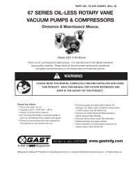
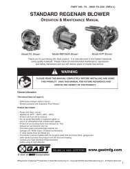
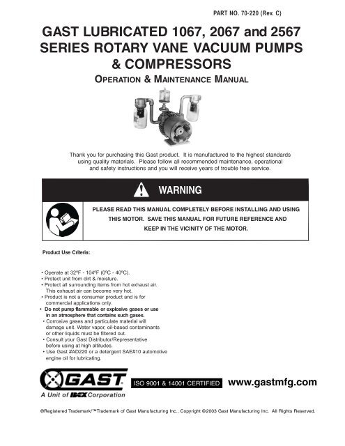
GAST LUBRICATED 1067, <strong>2067</strong> <strong>and</strong> <strong>2567</strong><br />
SERIES ROTARY VANE VACUUM PUMPS<br />
& COMPRESSORS<br />
OPERATION & MAINTENANCE MANUAL<br />
Thank you for purchasing this Gast product. It is manufactured to the highest st<strong>and</strong>ards<br />
using quality materials. Please follow all recommended maintenance, operational<br />
<strong>and</strong> safety instructions <strong>and</strong> you will receive years of trouble free service.<br />
WARNING<br />
PLEASE READ THIS MANUAL COMPLETELY BEFORE INSTALLING AND USING<br />
THIS MOTOR. SAVE THIS MANUAL FOR FUTURE REFERENCE AND<br />
KEEP IN THE VICINITY OF THE MOTOR.<br />
Product Use Criteria:<br />
• Operate at 32ºF - 104ºF (0ºC - 40ºC).<br />
• Protect unit from dirt & moisture.<br />
• Protect all surrounding items from hot exhaust air.<br />
This exhaust air can become very hot.<br />
• Product is not a consumer product <strong>and</strong> is for<br />
commercial applications only.<br />
• Do not pump flammable or explosive gases or use<br />
in an atmosphere that contains such gases.<br />
• Corrosive gases <strong>and</strong> particulate material will<br />
damage unit. Water vapor, oil-based contaminants<br />
or other liquids must be filtered out.<br />
• Consult your Gast Distributor/Representative<br />
before using at high altitudes.<br />
• Use Gast #AD220 or a detergent SAE#10 automotive<br />
engine oil for lubricating.<br />
ISO 9001 & 14001 CERTIFIED<br />
www.gastmfg.com<br />
®Registered Trademark/Trademark of Gast Manufacturing Inc., Copyright ©2003 Gast Manufacturing Inc. All Rights Reserved.
Your safety <strong>and</strong> the safety of others<br />
is extremely important.<br />
We have provided many important safety messages<br />
in this manual <strong>and</strong> on your product. Always read<br />
<strong>and</strong> obey all safety messages.<br />
This is the safety alert symbol. This symbol<br />
alerts you to hazards that can kill or hurt you <strong>and</strong><br />
others. The safety alert symbol <strong>and</strong> the words<br />
“DANGER” <strong>and</strong> “WARNING” will precede all safety<br />
messages. These words mean:<br />
INSTALLATION<br />
DANGER<br />
You will be killed or seriously injured if you don’t<br />
follow instructions.<br />
WARNING<br />
You can be killed or seriously injured if you don’t<br />
follow instructions.<br />
All safety messages will identify the hazard, tell you<br />
how to reduce the chance of injury, <strong>and</strong> tell you<br />
what can happen if the safety instructions are not<br />
followed.<br />
WARNING<br />
Injury Hazard<br />
Only pump air, never allow this pump to be used<br />
with any other gasses, fluids, particles, solids,<br />
COMBUSTIBLE SUBSTANCES or any substance<br />
mixed with air.<br />
WARNING<br />
Electrical Shock Hazard<br />
Disconnect electrical power at the circuit breaker<br />
or fuse box before installing this product.<br />
Install this product where it will not come into<br />
contact with water or other liquids.<br />
Install this product where it will be weather<br />
protected.<br />
Electrically ground this product.<br />
Failure to follow these instructions can result in<br />
death, fire or electrical shock.<br />
CAUTION Do not lift unit by fan shrouds. Unit<br />
should be lifted by means of eye bolt.<br />
CAUTION<br />
Do not block cooling air flow over<br />
pump in any way.<br />
WARNING Some models are equipped with<br />
glass jars. Proper measures should<br />
be taken to guard against glass<br />
fragmenting or braking if an<br />
alternative material is not used. If<br />
hazard is ignored severe personal<br />
injury or death can occur.<br />
Mounting Pump<br />
Pump base should be anchored to either a metal surface<br />
such as a shelf, floor or another piece of machinery. To<br />
save time <strong>and</strong> avoid inconvenience, position pump to<br />
provide easy access to all lubricators, filters <strong>and</strong> mufflers.<br />
Plumbing<br />
To prevent air flow restriction, use pipe <strong>and</strong> fittings that are<br />
the same size or larger than the threaded ports of the pump.<br />
The ports are marked "IN" <strong>and</strong> "OUT". If the distance is<br />
great, use lines with a larger diameter than the connections.<br />
Give lines a uniform slope, place drain cock at low point,<br />
<strong>and</strong> avoid extra elbows. For ease of servicing, use a union<br />
or hose with clamps near the pump (a hose helps eliminate<br />
noise <strong>and</strong> vibration). If a vacuum/pressure supply tank is<br />
used, slope the line towards tank, provide a drain at the<br />
bottom, <strong>and</strong> place a check valve between the tank <strong>and</strong><br />
pump so the pump will not run backwards when turned off.<br />
Accessories<br />
Intake <strong>and</strong> exhaust filters are external to the pump <strong>and</strong> will<br />
provide adequate filtration for most applications. Check<br />
filters periodically <strong>and</strong> replace when necessary. Consult a<br />
Gast Representative for additional filter recommendations.<br />
Install relief valves <strong>and</strong> gauges at the inlet or outlet, or both,<br />
to monitor performance. Check valves may be required to<br />
prevent backstreaming through the pump.<br />
Motor Control<br />
It is your responsibility to contact a qualified<br />
electrician to assure that the electrical installation is<br />
adequate <strong>and</strong> in conformance with all national <strong>and</strong> local<br />
codes <strong>and</strong> ordinances.<br />
Determine the correct overload setting required to<br />
protect the motor (see motor starter manufacturer’s<br />
recommendations). Select fuses, motor protective<br />
switches or thermal protective switches to provide<br />
protection. Fuses act as short circuit protection for the<br />
motor, not as protection against overload. Incoming line<br />
fuses help to withst<strong>and</strong> the motor’s starting current.<br />
Motor starters with thermal magnetic overload or circuit<br />
breakers protect motor from overload or reduced<br />
voltage conditions.<br />
The wiring diagram supplied with the product provides<br />
required electrical information. Check that power<br />
source is correct to properly operate the dual-voltage<br />
motors.<br />
2
Electrical Connection<br />
DIAGRAM A<br />
OPERATION<br />
WARNING<br />
Grounded Plug<br />
Grounding Pin<br />
120-volt grounded connectors<br />
shown. 220/240-volt grounded<br />
connectors will differ in shape. Grounded Outlet<br />
Model with a power supply cord:<br />
This product must be grounded. For either 120-volt or<br />
220/240-volt circuits connect power supply cord<br />
grounding plug to a matching grounded outlet. Do not<br />
use an adapter. (See DIAGRAM A)<br />
In the event of an electrical short circuit, grounding<br />
reduces the risk of electric shock by providing an<br />
escape wire for the electric current. This product may<br />
be equipped with a power supply cord having a<br />
grounding wire with an appropriate grounding plug.<br />
The plug must be plugged into an outlet that is properly<br />
installed <strong>and</strong> grounded in accordance with all local<br />
codes <strong>and</strong> ordinances.<br />
Check with a qualified electrician or serviceman if the<br />
grounding instructions are not completely understood,<br />
or if you are not sure whether the product is properly<br />
grounded. Do not modify the plug provided. If it will not<br />
fit the outlet, have the proper outlet installed by a<br />
qualified electrician.<br />
Model that is permanently wired:<br />
This product must be connected to a grounded,<br />
metallic, permanent wiring system, or an equipment<br />
grounding terminal or lead on the product.<br />
Power supply wiring must conform to all required safety<br />
codes <strong>and</strong> be installed by a qualified person. Check<br />
that supply voltage agrees with that listed on product<br />
nameplate.<br />
Extension cords:<br />
Use only a 3-wire extension cord that has a 3-blade<br />
grounding plug. Connect extension cord plug to a<br />
matching 3-slot receptacle. Do not use an adapter.<br />
Make sure your extension cord is in good condition.<br />
Check that the gage wire of the extension cord is the<br />
correct size wire to carry the current this product will<br />
draw.<br />
Minimum gage for extension cords<br />
Amps Volts Length of cord in feet<br />
120v 25 50 100 150 200 250 300 400 500<br />
240v 50 100 200 300 400 500 600 800 1000<br />
0-2 18 18 18 16 16 14 14 12 12<br />
2-3 18 18 16 14 14 12 12 10 10<br />
3-4 18 18 16 14 12 12 10 10 8<br />
4-5 18 18 14 12 12 10 10 8 8<br />
5-6 18 16 14 12 10 10 8 8 8<br />
6-8 18 16 12 10 10 8 6 6 6<br />
8-10 18 14 12 10 8 8 6 6 4<br />
10-12 16 14 10 8 8 6 6 4 4<br />
12-14 16 12 10 8 6 6 6 4 2<br />
14-16 16 12 10 8 6 6 4 4 2<br />
16-18 14 12 8 8 6 4 4 2 2<br />
18-20 14 12 8 6 6 4 4 2 2<br />
It is your responsibility to operate this product at<br />
recommended pressures or vacuum duties <strong>and</strong> room<br />
ambient temperatures. Do Not start against a vacuum or<br />
pressure load.<br />
Start Up<br />
If pump is extremely cold, let it warm up to room<br />
temperature before starting. If motor fails to start or<br />
slows down significantly under load, shut off <strong>and</strong><br />
disconnect from power supply. Check that the voltage is<br />
correct for motor <strong>and</strong> that motor is turning in the proper<br />
direction. Turning in the wrong direction will drastically<br />
reduce vane life. Vane life will be drastically reduced if<br />
motor is not operating properly. Vanes can break or be<br />
damaged if motor/pump runs in the wrong direction.<br />
MAINTENANCE<br />
Injury Hazard<br />
Install proper safety guards as needed. <strong>Pumps</strong> with<br />
glass jars need safety guards to protect against<br />
breaking glass.<br />
Use only recommended air h<strong>and</strong>ling parts<br />
acceptable for pressure not less than 70 psi..<br />
Keep fingers <strong>and</strong> objects away from openings <strong>and</strong><br />
rotating parts.<br />
When provided, motor terminal covers must be in<br />
place for safe operation.<br />
Check that coupling guard <strong>and</strong> shroud are in place<br />
before operating.<br />
Product surfaces may become hot during operation,<br />
allow product surfaces to cool before h<strong>and</strong>ling.<br />
Do Not direct air stream at body. Air stream from<br />
product may contain solid or liquid material that can<br />
result in eye or skin damage, wear proper eye<br />
protection.<br />
Do Not spray flammable or combustible liquid.<br />
Wear hearing protection. Sound level from product<br />
may exceed 85 dBA.<br />
Failure to follow these instructions can result in<br />
burns, eye injury or other serious injury.<br />
WARNING<br />
Electrical Shock Hazard<br />
Disconnect electrical power supply cord before<br />
performing maintenance on this product.<br />
If product is hard wired into system, disconnect<br />
electrical power at the circuit breaker or fuse box<br />
before performing maintenance on this product.<br />
Failure to follow these instructions can result in<br />
death, fire or electrical shock.<br />
3
Flushing<br />
Flushing this product to remove excessive dirt, foreign<br />
particles, moisture or oil that occurs in the operating<br />
environment will help to maintain proper vane<br />
performance. If your pump is not getting the vacuum or<br />
pressure level expected, flushing is required. Vanes will<br />
stick when dirty <strong>and</strong> may cause pump to be noisy or<br />
inefficient.<br />
Use only Gast recommended Flushing Solvent or other<br />
non-petroleum based flushing solvent. Do Not use<br />
kerosene or ANY other combustible solvent to flush<br />
product.<br />
It is your responsibility to:<br />
• Regularly inspect <strong>and</strong> make necessary repairs to<br />
product in order to maintain proper operation.<br />
• Make sure that pressure <strong>and</strong> vacuum is released<br />
from product before starting maintenance.<br />
Check intake <strong>and</strong> exhaust filters after first 500 hours of<br />
operation. Clean filters <strong>and</strong> determine how frequently<br />
filters should be checked during future operation. This<br />
one procedure will help to assure the productʼs<br />
performance <strong>and</strong> service life.<br />
Filter Inspection <strong>and</strong> Replacement<br />
WARNING Pump surfaces may become very hot<br />
during operation. Do not touch these<br />
parts until ump has been turned off<br />
<strong>and</strong> allowed to cool.<br />
Refer to exploded view during the following procedure:<br />
1. Turn off pump <strong>and</strong> isolate from power source<br />
2. Release all pressure <strong>and</strong> vacuum from pump.<br />
3. Remove glass filter/muffler jar<br />
4. Remove cartridges from intake <strong>and</strong> exhaust filters<br />
<strong>and</strong> inspect them.<br />
a. Check for cuts <strong>and</strong> excessive foreign material.<br />
1) If any of these conditions exists, replace<br />
immediately.<br />
2) If filters look serviceable, go to step 5.<br />
5. Clean them with compressed air <strong>and</strong> recheck for<br />
above conditions.<br />
a. If any of these conditions from step 4 show up,<br />
then replace immediately.<br />
6. Reassemble.<br />
1. Disconnect electrical power supply.<br />
2. Release all pressure <strong>and</strong> vacuum from pump.<br />
3. Remove all accessories at the inlet <strong>and</strong> exhaust<br />
ports.<br />
4. Remove filter.<br />
5. Start product. Place towel over exhaust port to<br />
clean up solvent. If using liquid solvent, pour<br />
several tablespoons directly into inlet port. If using<br />
Gast recommended Flushing Solvent, spray solvent<br />
for 5-10 seconds into inlet port.<br />
6. Block the inlet port <strong>and</strong> draw a deep vacuum for<br />
15-20 seconds. Release the vacuum.<br />
7. Listen for changes in the sound of the motor. If<br />
motor sounds smooth, go to next step. If motor<br />
does not sound like it is running smoothly, repeat<br />
steps 5 <strong>and</strong> 6 until you can hear a difference in the<br />
operating sound of the pump.<br />
8. Start the pump <strong>and</strong> let it run for 1 minute, then turn<br />
pump off.<br />
9. Replace all accessories at the inlet <strong>and</strong> exhaust<br />
ports.<br />
10. Replace filter before resuming operation.<br />
Check that all external accessories such as relief valves<br />
<strong>and</strong> gauges are attached to cover <strong>and</strong> are not damaged<br />
before re-operating product.<br />
SHUTDOWN PROCEDURES<br />
It is your responsibility to follow proper shutdown<br />
procedures to prevent product damage.<br />
Failure to do so may result in premature pump failure.<br />
The Gast Manufacturing lubricated <strong>Vacuum</strong> <strong>Pumps</strong> <strong>and</strong><br />
<strong>Compressors</strong> are constructed of ferrous metals or<br />
aluminum which are subject to rust <strong>and</strong> corrosion when<br />
pumping condensable vapors such as water. Follow the<br />
steps below to assure correct storage <strong>and</strong> shutdown<br />
between operating periods<br />
1. Disconnect plumbing.<br />
2. Operate product for at least 5 minutes without<br />
plumbing.<br />
3. Cover inlet port (vacuum side) <strong>and</strong> run pump for 1-3<br />
minutes. Shut the pump down under vacuum.<br />
4. This unit requires lubrication. Refill oil reservoir to<br />
proper level before storage.<br />
5. Be sure to plug open ports so dirt <strong>and</strong> other<br />
contaminants do not enter the unit. It is now ready<br />
for shutdown.<br />
4
SERVICE KIT INSTALLATION<br />
WARNING<br />
Electrical Shock Hazard<br />
Disconnect electrical power supply cord before<br />
installing Service Kit.<br />
If product is hard wired into system, disconnect<br />
electrical power at the circuit breaker or fuse box<br />
before installing Service Kit.<br />
Disconnect air supply <strong>and</strong> vent all air lines to<br />
release pressure or vacuum.<br />
Failure to follow these instructions can result in<br />
death, fire or electrical shock.<br />
Gast will NOT guarantee field-rebuilt product<br />
performance. For performance guarantee, the product<br />
must be returned to a Gast Authorized Service Facility.<br />
Service Kit contents vary. Most contain vanes, gaskets<br />
oiler wick <strong>and</strong> filter elements.<br />
Pump Disassembly:<br />
1. Remove fan, fan guard <strong>and</strong> (4) end cap screws.<br />
2. Remove dead end plate.<br />
3. Check for scoring on end plate, rotor <strong>and</strong> body.<br />
Surfaces should be smooth. If severe scoring is<br />
visible, contact an Authorized Service Facility<br />
4. Remove vanes<br />
5. Clean all surfaces with Gast recommended Flushing<br />
solvent <strong>and</strong> dry well.<br />
Pump Re-assembly<br />
6. Apply a light coat of Gast recommended Oil Part<br />
#AD220 (an equivalent 10 wt. high detergent oil can<br />
alsoo be used) to vanes.<br />
7. Re-install vanes, noting proper direction of beveled<br />
edge (refer to exploded view)<br />
8. Install dead end plate <strong>and</strong> install dead end plate bolts<br />
loosely.<br />
9. Install bearings into dead end plate; be sure to press<br />
inner race of bearing when installing.<br />
10. Reassemble end cap screws, fan guard <strong>and</strong> fan.<br />
11. Verify unit rotates freely by h<strong>and</strong> before reconnecting<br />
power.<br />
12. Before putting pump into service, ensure that any<br />
external accessories have not been damaged.<br />
13. Reconnect power.<br />
14. Check for proper rotation if unit is 3-phase.<br />
We have Gast Certified Service<br />
Centers throughout the world.<br />
For the most up-to-date listing,<br />
contact one of our sales offices :<br />
Gast Manufacturing, Inc.<br />
2300 S. Highway M139<br />
Benton Harbor, MI 49022<br />
Ph: 269/926-6171<br />
FAX: 269/925-8288<br />
www.gastmfg.com<br />
Gast Hong Kong<br />
Unit 12, 21/F, Block B<br />
New Trade Plaza<br />
6, On Ping Street, Shatin<br />
N. T. Hong Kong<br />
Ph: (852) 2690 1066<br />
Fax: (852) 2690 1012<br />
www.gasthk.com<br />
Gast Group Limited,<br />
United Kingdom<br />
Unit 11, The I O Centre<br />
Nash Road<br />
Redditch, B98 7AS<br />
United Kingdom<br />
ph: +44 (0) 1527<br />
Fax: +44 (0) 1527<br />
www.gastmfg.com<br />
Disposal (Please note current regulations)<br />
Parts of the rotary vane pumps <strong>and</strong><br />
compressors, shafts, iron or aluminum<br />
castings, plastic or glass parts or bearings,<br />
may be recycled as scrap materials.<br />
If pump fails to produce proper vacuum or pressure, or is<br />
excessively noisy, turn off <strong>and</strong> return unit to an Authorized<br />
Service Facility.<br />
5
EXPLODED PRODUCT VIEW<br />
1065 SERIES<br />
Note: Parts list on next page<br />
6
PARTS & ORDERING INFORMATION<br />
REF DESCRIPTION QTY VACUUM VACUUM VACUUM<br />
NO. PUMP COMPRESSOR PUMP COMPRESSOR PUMP COMPRESSOR<br />
1067-V1 1067-P2 <strong>2067</strong>-V1 <strong>2067</strong>-P2 <strong>2567</strong>-V1 <strong>2567</strong>-P2<br />
1 BODY 1 AH345 AH345 AH191 AH191 AH355 AH355<br />
2 ROTOR ASSEMBLY 1 AH428 AH428 AH192 AH192 AH192 AH192<br />
3 ∆ VANE 4 AH429 AH429 AA750D AA750D AH750D AH750D<br />
4 ∆ BODY SPACER 1 AH567H AH567H AH567H AH567H AH567H AH567H<br />
5 FOOT BRACKET 1 AH206 AH207 AH206 AH207 AH206 AH207<br />
6 ∆ BEARING (DRIVE & DEAD) 2 AH755D AH755D AH755D AH755D AH755D AH755D<br />
7 DRIVE END CAP 1 AB339A AB339A AB339A AB339A AB339A AB339A<br />
8 ∆ DRIVE SEAL 1 AC848 AC848 AC848 AC848 AC848 AC848<br />
9 FAN COUPLING ASSEMBLY 1 AH198 AH198 AH198 AH198 AH198 AH198<br />
10 FAN GUARD 1 AH194A AH194A AH194A AH194A AH194A AH194A<br />
11 DEAD END PLATE 1 AH203 AH204 AH203 AH204 AH203 AH204<br />
12 BELLEVILLE SPRINGS 2 AB337 AB337 AB337 AB337 AB337 AB337<br />
13 WASHER 1 AB338 AB338 AB338 AB338 AB338 AB338<br />
14 SNAP RING 1 AB335 AB335 AB335 AB335 AB335 AB335<br />
15 ∆ END CAP GASKET 1 AG467 AG467 AG467 AG467 AG467 AG467<br />
16 DEAD END CAP 1 AG466 AG466 AG466 AG466 AG466 AG466<br />
17 ∆ DEAD END SEAL 1 AC849 AC849 AC849 AC849 AC849 AC849<br />
18 FAN 1 AC326B AC326B AC326B AC326B AC326B AC326B<br />
19 FAN GUARD 1 AC102B AC102B AC102B AC102B AC102B AC102B<br />
20 VACUUM LUBRICATOR ASSM 1 V40C -- V40C -- V40C --<br />
21 PRESSURE LUBRICATOR 1 -- A380C -- AA95A -- AA95A<br />
22 OIL RESERVOIR ASSEMBLY 1 AA960-2 AA960-2 AA960-1 AA60-1 AA960-1 AA960-1<br />
23 INTAKE FILTER ASSM-COMP 1 -- AC432 -- AC435 -- AC435<br />
24 ∆ CARTRIDGE 1/2 (2) AC393 (1) AC393 (2) AC393 (1) AC393 (2) AC393 (1) AC393<br />
25 EXHAUST MUFFLER & OIL TRAP 1 AA800D -- AA900E -- AA900E --<br />
26 COVER GASKET 2 AA405 -- AA405 -- AA405 --<br />
27 GLASS JAR 2 AA401 -- AA401 -- AA401 --<br />
28 MUFFLER ELEMENT ASSM 2 AC434-1 -- AC436-1 -- AC436-1 --<br />
29 INTAKE FILTER ASSM-VACUUM 1 AA800C -- AA900D -- AA900D --<br />
30 INTAKE FILTER ELEMENT ASSM 1 AC433-1 -- AC435-1 -- AC435-1 --<br />
31 OIL CYLINDER 1 AA967A AA967A AA967A AA967A AA967A AA967A<br />
32 DIAPHRAGM 1 V33 -- V33 -- V33 --<br />
*** SERVICE KIT 1 K355 K355 K349 K349 K349 K349<br />
∆ Denotes parts included in the Service Kit.<br />
Parts listed are for stock models. For specific OEM models, please consult the factory.<br />
When corresponding or ordering parts, please give complete model <strong>and</strong> serial numbers.<br />
7
WARRANTY<br />
Gast finished products, when properly installed <strong>and</strong> operated under normal conditions of use, are warranted by Gast to<br />
be free from defects in material <strong>and</strong> workmanship for a period of twelve (12) months from the date of purchase from<br />
Gast or an authorized Gast Representative or Distributor. In order to obtain performance under this warranty, the buyer<br />
must promptly (in no event later than thirty (30) days after discovery of the defect) give written notice of the defect to<br />
Gast Manufacturing Incorporated, PO Box 97, Benton Harbor Michigan USA 49023-0097 or an authorized Service<br />
Center (unless specifically agreed upon in writing signed by both parties or specified in writing as part of a Gast OEM<br />
Quotation). Buyer is responsible for freight charges both to <strong>and</strong> from Gast in all cases.<br />
This warranty does not apply to electric motors, electrical controls, <strong>and</strong> gasoline engines not supplied by Gast. Gast’s<br />
warranties also do not extend to any goods or parts which have been subjected to misuse, lack of maintenance,<br />
neglect, damage by accident or transit damage.<br />
THIS EXPRESS WARRANTY EXCLUDES ALL OTHER WARRANTIES OR REPRESENTATIONS EXPRESSED OR<br />
IMPLIED BY ANY LITERATURE, DATA, OR PERSON. GAST’S MAXIMUM LIABILITY UNDER THIS EXCLUSIVE<br />
REMEDY SHALL NEVER EXCEED THE COST OF THE SUBJECT PRODUCT AND GAST RESERVES THE RIGHT,<br />
AT ITS SOLE DISCRETION, TO REFUND THE PURCHASE PRICE IN LIEU OF REPAIR OR REPLACEMENT.<br />
GAST WILL NOT BE RESPONSIBLE OR LIABLE FOR INDIRECT OR CONSEQUENTIAL DAMAGES OF ANY KIND,<br />
however arising, including but not limited to those for use of any products, loss of time, inconvenience, lost profit, labor<br />
charges, or other incidental or consequential damages with respect to persons, business, or property, whether as a<br />
result of breach of warranty, negligence or otherwise. Notwithst<strong>and</strong>ing any other provision of this warranty, BUYER’S<br />
REMEDY AGAINST GAST FOR GOODS SUPPLIED OR FOR NON-DELIVERED GOODS OR FAILURE TO FURNISH<br />
GOODS, WHETHER OR NOT BASED ON NEGLIGENCE, STRICT LIABILITY OR BREACH OF EXPRESS OR<br />
IMPLIED WARRANTY IS LIMITED SOLELY, AT GAST’S OPTION, TO REPLACEMENT OF OR CURE OF SUCH<br />
NONCONFORMING OR NON-DELIVERED GOODS OR RETURN OF THE PURCHASE PRICE FOR SUCH GOODS<br />
AND IN NO EVENT SHALL EXCEED THE PRICE OR CHARGE FOR SUCH GOODS. GAST EXPRESSLY DISCLAIMS<br />
ANY WARRANTY OF MERCHANTABILITY OR FITNESS FOR A PARTICULAR USE OR PURPOSE WITH RESPECT<br />
TO THE GOODS SOLD. THERE ARE NO WARRANTIES WHICH EXTEND BEYOND THE DESCRIPTIONS SET<br />
FORTH IN THIS WARRANTY, notwithst<strong>and</strong>ing any knowledge of Gast regarding the use or uses intended to be made<br />
of goods, proposed changes or additions to goods, or any assistance or suggestions that may have been made by Gast<br />
personnel.<br />
Unauthorized extensions of warranties by the customer shall remain the customer’s responsibility.<br />
CUSTOMER IS RESPONSIBLE FOR DETERMINING THE SUITABILITY OF GAST PRODUCTS FOR CUSTOMER’S<br />
USE OR RESALE, OR FOR INCORPORATING THEM INTO OBJECTS OR APPLICATIONS WHICH CUSTOMER<br />
DESIGNS, ASSEMBLES, CONSTRUCTS OR MANUFACTURES.<br />
This warranty can be modified only by authorized Gast personnel by signing a specific, written description of any<br />
modifications.<br />
TROUBLESHOOTING CHART<br />
Low High Pump Motor Reason <strong>and</strong> remedy<br />
<strong>Vacuum</strong> Pressure <strong>Vacuum</strong> Pressure Overheat Overload for problem.<br />
• • At pump • • Filter dirty.<br />
Clean or replace.<br />
• At pump • • Muffler dirty.<br />
Clean or replace.<br />
• At pump • • <strong>Vacuum</strong> line collapsed.<br />
Repair or replace.<br />
• • • • Relief valve set too high.<br />
Inspect <strong>and</strong> adjust.<br />
• • Relief valve set too low.<br />
Inspect <strong>and</strong> adjust.<br />
• • At pump At pump • • Plugged vacuum/pressure line.<br />
Inspect <strong>and</strong> repair.<br />
• • Vanes sticking.<br />
Clean or replace.<br />
• • Vanes worn.<br />
Replace.<br />
• • Shaft seal worn.<br />
Replace.<br />
• • • • Dust or offset powder in pump.<br />
Inspect <strong>and</strong> clean.<br />
• • • Motor not wired correctly.<br />
Check wiring diagram <strong>and</strong> line voltage.<br />
• • • • Running at too high an RPM.<br />
Check wiring diagram <strong>and</strong> line voltage.<br />
ISO 9001 & 14001 CERTIFIED<br />
www.gastmfg.com<br />
- 269-926-6171