Liquid Tin Corrosion and Lead Free Wave Soldering - EMSNow
Liquid Tin Corrosion and Lead Free Wave Soldering - EMSNow
Liquid Tin Corrosion and Lead Free Wave Soldering - EMSNow

You also want an ePaper? Increase the reach of your titles
YUMPU automatically turns print PDFs into web optimized ePapers that Google loves.
<strong>Liquid</strong> <strong>Tin</strong> <strong>Corrosion</strong> <strong>and</strong> <strong>Lead</strong> <strong>Free</strong> <strong>Wave</strong> <strong>Soldering</strong><br />
Jim Morris<br />
Speedline Technologies, Inc., Camdenton, MO<br />
Matthew J. O’Keefe, Ph.D., Martin Perez, PhD<br />
University of Missouri - Rolla, Rolla, MO<br />
Abstract<br />
<strong>Corrosion</strong> of solder pots <strong>and</strong> solder pot components in wave soldering equipment has been reduced with the introduction of<br />
corrosion resistant coatings <strong>and</strong> improved lead free solder alloys. The latest trends in protecting wave solder machine<br />
components from liquid metal corrosion by lead free solder alloys will be presented in order to provide guidelines for<br />
evaluating existing equipment as well as for purchasing new systems.<br />
New lead free alloys are available that are less corrosive than earlier Sn/Ag <strong>and</strong> Sn/Cu alloys <strong>and</strong> can be utilized in older,<br />
unprotected equipment for a longer period of time. Cast iron, titanium alloys, <strong>and</strong> stainless steels coated with titanium nitride<br />
<strong>and</strong> Melonite QPQ are discussed <strong>and</strong> evaluated. Coatings <strong>and</strong> materials evaluations are based upon chemical, structural, <strong>and</strong><br />
visual analysis along with field experience. Additionally, solder pot contamination sources, <strong>and</strong> tips on how to avoid<br />
contamination, are presented.<br />
Introduction<br />
The transition to lead free wave soldering in North America continues to increase. The European directives, China<br />
initiatives, RoHS, <strong>and</strong> competitive pressures are eliminating tin lead soldering at a fast pace. <strong>Lead</strong> free is here <strong>and</strong> wave<br />
solder process engineers must underst<strong>and</strong> the process <strong>and</strong> equipment impacts to succeed in the electronics assembly market.<br />
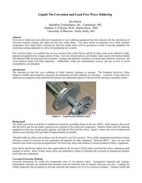
Figure 1 – Unprotected Stainless Steel<br />
Background<br />
The initial conversion to lead free in mainstream electronic assemblies began in the late 1990’s. Early adopters discovered<br />
that the Sn/Cu <strong>and</strong> Sn/Ag solders caused severe corrosion of the solder pot components. Stainless steels used for soldering<br />
equipment at that time would quickly degrade with high tin (Sn) lead free alloys. Figure 1 shows the result of unprotected<br />
stainless steel running in Sn/Ag solder for approximately six months.<br />
Alternate solder pot alloys <strong>and</strong> coatings were developed to resist Sn corrosion. <strong>Wave</strong> solder equipment manufacturers began<br />
offering a variety of solutions for new equipment <strong>and</strong> upgrades for older equipment. Melonite QPQ ® 1 , gray cast iron, <strong>and</strong><br />
titanium were found to provide good protection 2 for these early alloys <strong>and</strong> continue to remain popular for today’s equipment.<br />
Early Sn/Cu <strong>and</strong> Sn/Ag solders have been superceded by the Sn-Ag-Cu (SAC) alloys <strong>and</strong> lead free alloys containing small<br />
amounts of nickel. Some of these newer alloys are purported to reduce or eliminate the corrosion of unprotected stainless<br />
steel solder pot components.<br />
<strong>Corrosion</strong> Protection Methods<br />
<strong>Corrosion</strong> protections for solder pot components come in two generic types: homogenous materials <strong>and</strong> coatings.<br />
Homogenous materials are materials that naturally resist tin corrosion such as titanium <strong>and</strong> gray cast iron. Coatings are<br />
surface treatments that are applied to the base materials that imparts a level of tin corrosion resistance. Titanium nitride <strong>and</strong>
Melonite QPQ coatings are examples of surface treatments that are frequently used in soldering equipment. All of these<br />
materials exhibit good corrosion resistance to tin <strong>and</strong> have a proven track record in actual field application.<br />
Homogeneous Materials<br />
Gray Cast Iron – Gray cast iron has proven to be a material that resists tin corrosion <strong>and</strong> is a preferred material for solder pot<br />
construction. One way to estimate the dissolution of one material to another is through use of phase diagrams. The more<br />
soluble one material is to another (as indicated by the phase diagram), the more likely erosion or corrosion will occur. Figure<br />
2 below shows the Sn/Fe phase diagram in the range of 99.5% to 100.0% Sn.<br />
Figure 2 - Sn Rich Part of Fe-Sn Phase Diagram 2<br />
Per the phase diagram, Sn can only hold a maximum of 0.001% Fe in solution at 265°C (510°F). This very low amount of Fe<br />
that can be held by the molten tin is a good indicator that Fe would not be easily dissolved by molten Sn at soldering<br />
temperatures.<br />
Graphite (carbon) flakes, found in gray cast iron, are insoluble in molten Sn. These flakes act as a barrier <strong>and</strong> reduce the<br />
possibility of erosion. Figure 3 below shows a cross section of a gray cast iron solder pot after exposure to Sn/Ag solder. 3<br />
Graphite Flakes<br />
Cast Iron<br />
Solder<br />
Figure 3 - Cast Iron Cross Section<br />
Seven years of field data for cast iron operating in Sn/Ag <strong>and</strong> SAC solder indicate no noticeable erosion of the cast iron<br />
solder pot or detrimental changes to the soldering process. Advantages of gray cast iron include good corrosion resistance,<br />
an economical material, <strong>and</strong> homogeneous (non-welded) construction. A disadvantage is that it is impractical for internal<br />
solder pot components due to the tooling costs involved.<br />
Titanium – Titanium has been utilized for solder pots, solder pot liners, hardware, <strong>and</strong> nozzle components <strong>and</strong> has been<br />
exceptional in resisting the corrosive effects of Sn based lead free solders. The common alloy used is commercially pure<br />
grades 1, 2, 3, & 4. Commercially pure grades contain 99% Titanium <strong>and</strong> show no evidence of corrosion at common wave<br />
solder temperatures.
Figure 4 shows titanium coupons, exposed to Sn/Ag solder for 8 weeks at 250°C (482°F). No evidence of liquid metal<br />
corrosion of the titanium material is exhibited 3 . In comparison, type 304 stainless steel showed evidence of wetting after two<br />
weeks exposure under these same conditions.<br />
Figure 4 -Titanium SamplesAfter Sn/Ag Exposure<br />
Phase diagram analysis supports the field experience for titanium components. At the common soldering temperature of<br />
265°C (510°F), less than 0.001% Ti can be held in solution with Sn. Figure 5 shows the Sn-Ti phase diagram.<br />
Figure 5 – Sn-Ti phase diagram 4<br />
As temperature increases, the amount of Ti that can be dissolved into Sn increases at faster rate than does cast iron.<br />
Utilization of titanium in solder pots for high temperature tinning applications 436°C (800°F) is not recommended. At these<br />
elevated temperatures, corrosion rates for titanium are given in the ASM H<strong>and</strong>book of <strong>Corrosion</strong> Data 5 as 1.0 mm per year<br />
versus 0.25mm per year for cast iron.<br />
Field experience with commercially pure alloys indicates that Ti is a superior material for lead free equipment applications.<br />
Titanium has superior corrosion resistance at soldering temperatures <strong>and</strong> can be readily formed into various shapes.<br />
However, Ti is very costly, the material supply can be disrupted, <strong>and</strong> it is difficult to weld.<br />
Older wave solder systems, that use a stainless steel pot, are often obsolete <strong>and</strong> replacement parts unavailable from the<br />
manufacturer. Utilizing a titanium liner in these systems can extend the life of the machine if no other choice is available.<br />
The fit of a liner to the solder pot is extremely important to avoid solder pot heater burnout. Additionally, drain valve<br />
provisions will no longer be useful once a liner is in place.<br />
Surface Treatments<br />
Titanium Nitride – A TiN coating is commonly used on metal cutting tools to increase durability. In recent years it has found<br />
popularity in coating solder pot components for resistance to Sn corrosion. Titanium nitride is applied through a vacuum<br />
deposition process <strong>and</strong> has a high hardness (85 Rc) <strong>and</strong> a low coefficient of friction (0.65 against steel) 6 .<br />
Evaluation of TiN coated samples in Pb-free solders has been conducted 7 . To determine suitability for use in lead free solder,<br />
a sample solder pump impellor was coated with titanium nitride <strong>and</strong> exposed to SAC solder for six weeks at 316°C (600°F).<br />
At the conclusion of the exposure the sample was subjected to a tape adhesion test. The solder easily peeled away from the<br />
coated sample, indicating no signs of wetting to the TiN coated sample. The sample was then sectioned, polished, <strong>and</strong><br />
examined by metallography, X-ray diffraction, Auger analysis, electron microscopy, <strong>and</strong> chemical analysis 7 . Figure 6 below<br />
shows the test sample after exposure to SAC solder.
Figure 6 – TiN coated 316 stainless steel impellor<br />
Figure 7 – Digital micrographs of areas of<br />
Titanium nitride coating on sample 1, (400X)<br />
No TiN/Sn reaction products were observed in the digital micrographs (Figure. 7). The gold color is characteristic of TiN<br />
<strong>and</strong> X-ray diffraction indicated that the coating was TiN <strong>and</strong> not Ti 2 N or other phase.<br />
Chemical analysis was performed in a scanning electron microscope (SEM) using energy dispersive spectroscopy (EDS),<br />
with the results given in Figure 8 <strong>and</strong> Table 1.<br />
Figure 8 - Designations of areas analyzed with EDS. (3000X) EDS results in Table 1.<br />
Table 1. Results of St<strong>and</strong>ardless EDS Tests.<br />
Area Label Major elements (>10%) Minor elements (
TiN is a costly process. Many of the parts coated are as costly as building the parts from commercially pure titanium. Also,<br />
the TiN vacuum deposition coating is not as thick through holes, tubes, <strong>and</strong> interior passages. Interiors of solder flow ducts<br />
will receive minimal to no protection.<br />
Melonite QPQ –Originally this coating was used in small solder stations to protect the solder pot <strong>and</strong> components from early<br />
corrosive alloys used in industrial <strong>and</strong> specialty electronic soldering. With the move to lead free wave soldering it has<br />
become a mainstay for protecting solder pot components from the corrosive molten Sn lead free solder.<br />
The Melonite coating consists of two layers: a compound layer <strong>and</strong> a diffusion layer. The compound layer consists of ε-iron<br />
nitride (Fe 3 N) that is a hard, chemically stable material <strong>and</strong> is primarily responsible for the improved corrosion resistance.<br />
The diffusion layer is γ-iron nitride (Fe 4 N) <strong>and</strong> is responsible for improved material fatigue strength. Figure 9 shows typical<br />
components that are Melonite QPQ coated.<br />
Figure 9 – Melonite Coated Components<br />
Metallurgical testing <strong>and</strong> analysis was conducted on this coating in 2001-2002 3 which confirmed that this material would be a<br />
durable protection method for wave solder internal solder pot components.<br />
Field experience indicates that MeloniteQPQ coated components withst<strong>and</strong> Sn corrosion very well. Advantages of Melonite<br />
include good corrosion resistance, low cost, coverage of interior passages, <strong>and</strong> availability. The disadvantage is that<br />
Melonite is a coating <strong>and</strong> if damaged the underlying substrate will be exposed to the corrosive environment.<br />
New <strong>Lead</strong> <strong>Free</strong> Alloys<br />
In the early days of lead free wave soldering, Sn/Ag <strong>and</strong> Sn/Cu were the commonly used alloys. Both of these alloys were<br />
very corrosive to stainless steel <strong>and</strong> thus drove the initial development of protection methods for solder pot components. As<br />
material technology has progressed, SAC alloys <strong>and</strong> alloys containing nickel replaced these early alloys due to improved<br />
solder results <strong>and</strong> costs.<br />
Along with the improved results, these later alloys tend to be less corrosive to stainless steel than the previous Sn/Ag <strong>and</strong><br />
Sn/Cu alloys. Specifically, the alloys containing nickel have shown positive results in terms of minimizing the corrosion of<br />
stainless steel solder components. For wave solder equipment that cannot be upgraded with the newer corrosion resistant<br />
materials, the Sn based solder alloys that contain nickel provide a viable alternative in extending the life of this older<br />
equipment.<br />
Laboratory testing was conducted on Type 304 stainless steel samples by exposing them to SN100C solder at 260°C (500°F)<br />
for two <strong>and</strong> four weeks. After exposure the samples were sectioned <strong>and</strong> examined by several methods including; tape test,<br />
SEM analysis, EDS analysis, <strong>and</strong> AES analysis.<br />
Tape test results indicated that the solder easily peeled away, with no wetting or reaction products observed. Sectioning was<br />
performed <strong>and</strong> backscatter electron imaging was conducted.
Figure 10 shows backscatter electron (BSE) images of the stainless steel strips. Table 2 lists elements detected by EDS at<br />
selected locations. Very limited wetting of the surface was observed on the samples, because BSE images did not show any<br />
form of a reaction product on the stainless steel (SST). The solder layer separated from the surfaces of the SST strips. EDS<br />
of the specimen showed Fe was the major constituent with Ni <strong>and</strong> Cr as minor elements.<br />
C<br />
I<br />
B<br />
H<br />
G<br />
A<br />
F<br />
E<br />
A. #01 SST, 2wk exposure (200X) B. #02 SST, 4wk exposure (200X)<br />
D<br />
Figure 10 - BSE images of SST-solder cross sections for #01 <strong>and</strong> #02 (20kV). A separation of SST <strong>and</strong> solder<br />
is seen on the left side of Fig. 10A.<br />
Table 2: Elements Detected in Selected Locations of #01 & #02 Cross Sections Refer to Figure 10 for<br />
locations.<br />
Sample Location Flag in BSE Image Elements Detected<br />
#01 304 SST A Fe, Ni, Cr<br />
Solder (light gray) B Sn, Cu<br />
Solder (rough gray) C Sn, Cu<br />
#02 304 SST D Fe, Ni, Cr<br />
Solder (rough gray close E<br />
Sn,Cu, Fe (trace)<br />
to SST)<br />
Solder (rough gray F<br />
Sn<br />
away from SST)<br />
Solder (black phase) G Si<br />
Solder (light gray) H Sn<br />
Solder (dark gray) I Sn, Fe, Cu<br />
There was some Fe, Cu <strong>and</strong> possibly Ni detected in the solder layers. The presence of Fe in the SN100C solder suggests that<br />
a small amount of erosion of the SST surface was possible. In comparison, the same testing conducted on stainless steel<br />
samples exposed to Sn/Ag solder exhibited observable wetting <strong>and</strong> erosion after two week exposure. These results indicate a<br />
material that is many times less corrosive to stainless steel than the Sn/Ag <strong>and</strong> Sn/Cu alloys.<br />
Material <strong>and</strong> Alloys Summary<br />
It is important for equipment suppliers <strong>and</strong> wave solder process engineers to recognize that there is not one material or alloy<br />
that is suitable for every application. <strong>Wave</strong> solder equipment manufacturers must work with their customers <strong>and</strong> evaluate<br />
each lead free conversion opportunity <strong>and</strong> select the best solution. Safety, cost, desired equipment life, <strong>and</strong> process<br />
requirements will drive the material selection.<br />
A solder pot made from a coated material must be inspected for degradation much more frequently than a solder pot made<br />
from a material that is naturally resistant to lead free solders, such as cast iron. As coatings can become damaged,<br />
catastrophic failure can occur if this damage remains unnoticed <strong>and</strong> the entire contents of molten solder leak onto the floor of<br />
the factory.
An equipment purchaser who desires equipment to run trouble free for 10 years or more should consider commercially pure<br />
titanium for the interior components. On the other h<strong>and</strong>, if purchasing equipment for a specific contract, capital equipment<br />
costs can be reduced by utilizing coated solder nozzles. Utilizing coated components, however, requires more care be taken<br />
during maintenance activities to avoid damage to the coatings.<br />
To assist the process engineer with the selection of wave solder machine components <strong>and</strong> materials, the following table is<br />
provided as a guideline for choosing materials <strong>and</strong> verifying their performance.<br />
Table 3 – Summary of Material Recommendations<br />
Material Pros Cons Recommended Uses Inspection<br />
Frequency<br />
Commercially<br />
Pure<br />
Titanium<br />
Melonite<br />
Coated<br />
Stainless Steel<br />
TiN Coated<br />
Stainless Steel<br />
Gray<br />
Iron<br />
Cast<br />
Extremely resistant<br />
to effects of <strong>Tin</strong> at<br />
lead free soldering<br />
temperatures.<br />
Inexpensive <strong>and</strong><br />
good corrosion<br />
resistance. Dip<br />
coating process.<br />
Interior channels<br />
can be coated <strong>and</strong><br />
protected.<br />
Good corrosion<br />
resistance.<br />
Inexpensive.<br />
Excellent<br />
Resistance to <strong>Tin</strong>rich<br />
solder.<br />
Resistant at high<br />
soldering<br />
temperatures.<br />
Very expensive.<br />
Impractical to manufacture<br />
many components. Welding<br />
difficult. Not suitable for<br />
high temp soldering > 350°C<br />
Areas subject to frequent<br />
maintenance or cleaning.<br />
Internal solder module<br />
components where long<br />
life is required.<br />
Will degrade if damaged. Internal solder module<br />
components.<br />
Expensive. Will degrade if<br />
damaged.<br />
Inability to coat interiors of<br />
ducts <strong>and</strong> tubes.<br />
Each component must have<br />
tooling produced.<br />
Not recommended for<br />
solder pot.<br />
Internal Solder module<br />
components. Nozzles,<br />
impellors, pump shafts.<br />
Not recommended for<br />
solder pot.<br />
Safety<br />
critical<br />
components (main solder<br />
pot).<br />
Inspect for<br />
degradation<br />
every two<br />
years.<br />
Inspect<br />
Quarterly.<br />
Inspect<br />
Quarterly.<br />
Inspect<br />
annually.<br />
Low<br />
<strong>Corrosion</strong><br />
<strong>Lead</strong> <strong>Free</strong><br />
Solders<br />
Very little to no<br />
corrosiveness to<br />
stainless steel.<br />
As with all lead free alloys<br />
acceptable defect rate must<br />
be verified.<br />
Obsolete equipment with<br />
unprotected stainless steel<br />
components.<br />
Inspect<br />
Quarterly.<br />
<strong>Lead</strong> <strong>Free</strong> Alloy Contamination<br />
With the cost of lead free solder constantly increasing in price, underst<strong>and</strong>ing how to avoid metallic contaminates in the lead<br />
free solder has become an important topic. Upon discovering that a particular contaminant is increasing in the solder alloy,<br />
the common reaction is that it must be coming from the equipment. However, metallic contaminates come from unexpected<br />
sources <strong>and</strong> sometimes the PCB itself. The following are tips on the likely causes of an undesired element in the solder alloy.<br />
These tips derive from process experiences over the past several years.<br />
Anti-Seize Compound – <strong>Wave</strong> solder machines utilize anti-seize on threaded fasteners for the solder pot <strong>and</strong> solder pot<br />
components. This compound comes in a variety of formulas containing different metallic particles to prevent threaded<br />
fasteners from “seizing” under high temperatures. The proper compound should not contain metallic particles that are<br />
considered contaminates to lead free solder. If copper-based or nickel-based anti-seize compounds are used during<br />
maintenance of the wave solder machine, these will get into the solder bath.<br />
PCB/Pallet Hardware – Assemblies with metallic hardware on the bottom of the PCB or pallets that have exposed hardware<br />
that passes through the wave have caused a gradual contamination of the solder bath. Nickel-plated hardware running<br />
through the solder wave has caused problems at several facilities around the world.
PCB substrate <strong>and</strong> components – <strong>Lead</strong> free solder readily dissolves copper <strong>and</strong> nickel from the circuit traces <strong>and</strong> component<br />
leads as soldering occurs. Frequent monitoring of the solder pot metallurgy, early corrective action to the alloy, <strong>and</strong><br />
optimizing for the minimum solder dwell time in the wave can reduce this type of contamination.<br />
Tools/hardware dropped in solder pot – Stainless steel has a higher density than the common lead free alloys <strong>and</strong> will sink to<br />
the bottom of a solder pot. Over time, these tools will degrade releasing Nickel <strong>and</strong> Chromium into the solder.<br />
Damaged or non-protected solder pot components – Older equipment that has not been upgraded with the newer coated type<br />
nozzle components will corrode with many of the lead free alloys. Also, coated nozzles in which the coating has been<br />
damaged will release unwanted metals into the solder bath.<br />
Wrong alloy – It is key to have a material control program in place to segregate solder alloys <strong>and</strong> reduce the likelihood of an<br />
operator accidentally putting the wrong solder in the machine. Many instances of lead contamination are because the lead<br />
solder has not been properly controlled. New triangle shaped lead free solder bars <strong>and</strong> “poke yoke” type bar feeders have<br />
reduced this problem but it is key to have process in place to segregate <strong>and</strong> control solder bar in a facility.<br />
Conclusions<br />
<strong>Lead</strong> free solder can be used in pre-existing <strong>and</strong> new wave solder machines if appropriate materials are used in the<br />
construction of the soldering unit. Solder pots should be made of gray cast iron or other naturally corrosion-resistant<br />
material. When coated materials must be used for solder pot construction, care must be taken to inspect for possible<br />
degradation. Melonite QPQ <strong>and</strong> TiN coated materials are good solutions for the internal solder pot components <strong>and</strong> have<br />
proven resistive to Sn corrosion in the field. <strong>Lead</strong> free alloys containing nickel exhibit minimal corrosion when used with<br />
unprotected stainless steel <strong>and</strong> can be a good solution to extend the life of older machines. Contamination of lead free<br />
solder can be caused by many factors <strong>and</strong> ,in most cases, is not equipment related. All possible sources of contamination<br />
should be considered <strong>and</strong> evaluated to fully underst<strong>and</strong> this problem.<br />
Acknowledgements<br />
The authors would like to thank Richard Szymanowski, wave solder applications engineer, Speedline Technologies, for his<br />
insights into solder pot contamination sources <strong>and</strong> Vanessa Eckhoff at UMR for working on the TiN coatings. In addition,<br />
we appreciate <strong>and</strong> acknowledge the following students of the UMR Metallurgical Engineering Department, whose research<br />
<strong>and</strong> work on their senior design projects set the foundation for protection of wave solder components used in the industry<br />
today: Kristen Hartman, William Blair, Nicholas Cook, Allen Birschbach, Heather Davenport, Matt Cavins, Jason Carter,<br />
Lucie Johannes, <strong>and</strong> Benjamin Yenicek.<br />
References<br />
1. Kolene Corp. website (www.finishing.com/lolene/qpq); last accessed December 1, 2002.<br />
2. Okamoto, H. “Phase Diagrams of Ninary Iron Alloys:, ASM Intl. Society, 1993, pgs. 222, 385, <strong>and</strong> 387<br />
3. Carter, Johannes, <strong>and</strong> Yenicek. “<strong>Tin</strong> Solder <strong>Corrosion</strong> of <strong>Wave</strong> <strong>Soldering</strong> Components”. Met 316 Report, 12, 2001.<br />
4. Massalski, T. B., Editor-in-Chief. “Binary Alloy Phase Diagrams: 2 nd Ed.; ASM Intl., 1990, Vol. 2: pgs.160, 370.<br />
5. ASM H<strong>and</strong>book of <strong>Corrosion</strong> Data, 2 nd Edition, 1995, pp. 499-504.<br />
6. Brycoat Corp Website (www.brycoat.com) ; last accessed Nov. 10, 2006.<br />
7. Perez, Martin, <strong>and</strong> Vanessa Eckhoff. “Effect of SAC Solder on a Titanium Nitride Coated Impeller”. Graduate Center for<br />
Materials Research, University of Missouri, Rolla, MO, February 4, 2005.