HRC™ Couplings - Poulsen
HRC™ Couplings - Poulsen
HRC™ Couplings - Poulsen

You also want an ePaper? Increase the reach of your titles
YUMPU automatically turns print PDFs into web optimized ePapers that Google loves.
DRIVE COUPLINGS<br />
HRC <strong>Couplings</strong> - Dimensions<br />
5<br />
Section<br />
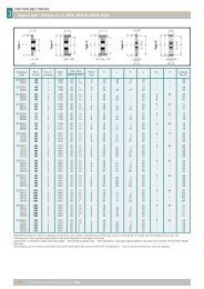
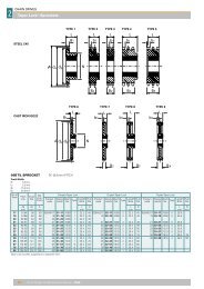
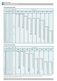
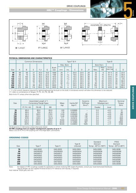
PHYSICAL DIMENSIONS AND CHARACTERISTICS<br />
Common Dimensions Type F & H Type B<br />
Max. Bore<br />
Bore Dia's<br />
Bush Pilot Screw<br />
Size A B E F 1<br />
‡ G size mm ins. C D J† Max. H9 over key C D<br />
70 69 60 31 25.0 18.0 1008 25 1" 20.0 23.5 29 32 8 M 6 20 23.5<br />
90 85 70 32 30.5 22.5 1108 28 1 1 /8 19.5 23.5 29 42 10 M 6 26 30.0<br />
110 112 100 45 45.0 29.0 1610 42 1 5 /8 18.5 26.5 38 55 10 M10 37 45.0<br />
130 130 105 50 53.0 36.0 1610 42 1 5 /8 18.0 26.5 38 60 15 M10 39 47.5<br />
150 150 115 62 60.0 40.0 2012 50 2 23.5 33.5 42 70 20 M10 46 56.0<br />
180 180 125 77 73.0 49.0 2517 60 2 1 /2 34.5 46.5 48 80 25 M10 58 70.0<br />
230 225 155 99 85.5 59.5 3020 75 3 39.5 52.5 55 100 25 M12 77 90.0<br />
280 275 206 119 105.5 74.5 3525 100 4 51.0 66.5 67 115 30 M16 90 105.5<br />
† 'J' is the wrench clearance required for tightening/loosening the bush on the shaft. A shortened wrench will allow this dimension to be reduced.<br />
‡ F 1<br />
refers to combinations of flanges: FF, FH, HH, FB, HB, BB.<br />
Bore limits H7 unless otherwise specified.<br />
Assembled Length (L*) Dynamic Maximum Nominal<br />
Size Comprising Flange Types Mass Inertia Mr 2 Stiffness Misalignment Torque<br />
(kg) (kgm 2 ) (Nm/ O ) (Nm)<br />
FF. FH. HH FB.HB BB Parallel Axial<br />
70 65.0 65.0 65.0 1.00 0.00085 – 0.3 +0.2 31<br />
90 69.5 76.0 82.5 1.78 0.00115 – 0.3 +0.5 80<br />
110 82.0 100.5 119.0 5.00 0.00400 65 0.3 +0.6 160<br />
130 89.0 110.0 131.0 5.46 0.00780 130 0.4 +0.8 315<br />
150 107.0 129.5 152.0 7.11 0.01810 175 0.4 +0.9 600<br />
180 142.0 165.5 189.0 16.60 0.04340 229 0.4 +1.1 950<br />
230 164.5 202.0 239.5 26.00 0.12068 587 0.5 +1.3 2000<br />
280 207.5 246.5 285.5 50.00 0.44653 1025 0.5 +1.7 3150<br />
All dimensions in millimetres unless otherwise stated.<br />
All HRC couplings have an angular misalignment capacity of up to 1º.<br />
Mass is for an FF, FH or HH coupling with mid range Taper Lock Bushes.<br />
DRIVE COUPLINGS<br />
ORDERING CODES<br />
Standard<br />
FRAS<br />
Type B Element Element<br />
Size Type F Type H Unbored Tempr. -40 O C/+100 O C Tempr. -20 O C/+80 O C<br />
70 045L0002 045L0003 045L0004 045L0009 045L0006<br />
90 045M0002 045M0003 045M0004 045M0009 045M0006<br />
110 045N0012 045N0013 045N0004 045N0009 045N0006<br />
130 045P0002 045P0003 045P0004 045P0009 045P0006<br />
150 045R0002 045R0003 045R0004 045R0009 045R0006<br />
180 045S0002 045S0003 045S0004 045S0009 045S0006<br />
230 045T0002 045T0003 045T0001 045T0009 045T0006<br />
280 045U0002 045U0003 045U0001 045U0009 045U0006<br />
Note: For details of HRC couplings suitable for application to drives involving SAE engine flywheels, consult your local Authorised Distributor.<br />
Type B flanges can be supplied finished bored to H7 tolerance with keyway, if required.<br />
Hub material: GG25 grey cast iron.<br />
Drive Design & Maintenance Manual - 2006 117