Optidrive E2 User Guide - Fenner® Power Transmission
Optidrive E2 User Guide - Fenner® Power Transmission
Optidrive E2 User Guide - Fenner® Power Transmission

Create successful ePaper yourself
Turn your PDF publications into a flip-book with our unique Google optimized e-Paper software.
Insatallation & Operating Instructions3. Mechanical Installation3.1. Mechanical dimensions and mountingFrame Size 2Overall DimensionsHeightWidthDepthA260mm100mm175mm210mmB 92mmIncoming <strong>Power</strong> Terminals C 25mmHelp CardKeypad & Display – See Section 4.8 on page 12Footprint ViewRJ11 Connector – See Section 10.3 on page 30Infra Red InterfaceControl Terminals – See Section 4.7 on page 12Motor & Brake Resistor ConnectionTerminalsWeight:2.6kgFixings: 2 x M4 Keyhole slots<strong>Power</strong> Terminals Torque Setting: 1NmFrame Size 3Overall DimensionsHeightWidth260mm171mmDepthAB175mm210mm163mmIncoming <strong>Power</strong> Terminals C 25mmHelp CardKeypad & Display – See Section 4.8 on page 12Footprint ViewRJ11 Connector – See Section 10.3 on page 30Infra Red InterfaceControl Terminals – See Section 4.7 on page 12Motor & Brake Resistor Connection TerminalsWeight:5.3kgFixings: 4 x M4 Keyhole slots<strong>Power</strong> Terminals Torque Setting: 1Nm6 www.fptgroup.com Fenner is a registered Trademark of J.H Fenner & Co Limited
Insatallation & Operating InstructionsFrame Size 4Overall DimensionsHeight 520mmWidth 340mmDepth 220mmA 420mmB 320mmIncoming <strong>Power</strong> Terminals C 50mmHelp CardKeypad & Display – See Section 4.8 on page 12Footprint ViewRJ11 Connector – See Section 10.3 on page 30Infra Red InterfaceControl Terminals – See Section 4.7 on page 12Motor & Brake Resistor Connection TerminalsWeight:28kgFixings: 4 x M8 Keyhole slots<strong>Power</strong> Terminals Torque Setting: 4NmFrame Sizes 5 & 6Overall DimensionsHeightWidthDepthAB1100mm340mm330mm945mm320mmIncoming <strong>Power</strong> Terminals C 50mmHelp CardKeypad & Display – See Section 4.8 on page 12RJ11 Connector – See Section 10.3 on page 30Infra Red InterfaceControl Terminals – See Section 4.7 on page 12Motor & Brake Resistor Connection TerminalsFootprint ViewWeights:Size 5: 67KgSize 6: 55Kg(+ 27Kg Choke)Fixings: 4 x M8 Keyhole slots<strong>Power</strong> Terminals Torque Setting: 8NmFenner is a registered Trademark of J.H Fenner & Co Limited www.fptgroup.com 7
Insatallation & Operating Instructions4.4. Connection DiagramDefault Analogue andDigital InputConnections4.5. Motor connections and cables• The motor should be connected to U, V, and W terminals• To comply with EMC directives, shielded cable should be used with the shield bonded to earth at the drive and motor ends.• Further information can be found in the Advanced <strong>User</strong> <strong>Guide</strong>.4.6. Motor Terminal Box ConnectionsMost general purpose motors are wound for operation on dual voltage supplies; this is indicated on the nameplate of the motor.This operational voltage is normally selected when installing the motor by selecting either STAR or DELTA connection. STAR always givesthe higher of the two voltage ratings.Incoming SupplyVoltageMotor NameplateVoltagesConnection230 230 / 400Delta400 400 / 690400 230 / 400 StarFenner is a registered Trademark of J.H Fenner & Co Limited www.fptgroup.com 11
Insatallation & Operating Instructions4.7. Control terminal connectionsDefault ConnectionsControlTerminalSignalDescription1 +24V <strong>User</strong> Output, +24V, 100mA user control output2 Digital Input 134Digital Input 2 /Digital Output 3Digital Input 3 /Analogue Input 2Positive logic“Logic 1” input voltage range: 8V … 30V DC“Logic 0” input voltage range: 0V … 8V DCInput: Positive logic“Logic 1” input voltage range: 8V … 30V DC“Logic 0” input voltage range: 0V … 8V DCOutput: 24V 10mA Max ‘Drive Healthy’ OutputDigital: “Logic 1” input voltage range: 8 to 30V DC“Logic 0” input voltage range: 0 to 8 V DCAnalogue: 0 to 10V, 0 to 20mA or 4 to 20mA5 +24V <strong>User</strong> Output +24V, 100mA, 1kΩ minimum6Bipolar analogInput /Digital Input 4Digital: “Logic 1” input voltage range: 8 to 30V DC“Logic 0” input voltage range: 0 to 8 V DCAnalogue: 0 to 24V, 0 to 10V, -10 to +10V, -24 to + 24V7 0V <strong>User</strong> ground, connected to terminal 98Analogue Output /Digital OutputAnalogue: 0 to 10V DC, 20mA MaximumDigital: 0 to 24V DC, 20mA Maximum9 0V <strong>User</strong> ground, connected to terminal 710 Relay Common11Relay NOContactVolt free contacts. Maximum load should not exceed250Vac, 6A / 30Vdc, 5A4.8. Electromagnetic CompatibilityAll QD:VT Drives are designed to high standards of EMC and are fitted with an internal EMC filter. This EMC filter is designed to reduce theconducted emissions back into the supply via the power cables for compliance with harmonised European standards.It is the responsibility of the installer to ensure that the equipment or system into which the product is incorporated complies with the EMClegislation of the country of use. Within the European Union, equipment into which this product is incorporated must comply with 89/336/EEC,EMC. When using the internal filter, the following maximum motor cable lengths apply:-Screened Motor Cable LengthDrive Frame SizeWith Internal FilterC1 C2 C3230 Volt 1 phase InputSize 2 1m 5m 25m400 Volt 3 phase InputSize 2 5m 25m 50mSize 3 5m 25m 50mSize 4 5m 25m 50mSize 5 5m 25m 50mSize 6 5m 25m 50mFor motor cable lengths greater than 100m, an output dv/dt filter must be used, please contactNotesyour Fenner Drives distributor for further details.For Size 5 and 6 drives, a ferrite ring must be installed on the output motor cable, with all threephases of the motor cable being wrapped one turn around the ferrite ring.12 www.fptgroup.com Fenner is a registered Trademark of J.H Fenner & Co Limited
Insatallation & Operating Instructions5. Operation5.1. Managing the keypadThe drive is configured and its operation monitored via the keypad and display.NAVIGATEUPDOWNUsed to display real-time information, to access andexit parameter edit mode and to store parameterchangesUsed to increase speed in real-time mode or toincrease parameter values in parameter edit modeUsed to decrease speed in real-time mode or todecrease parameter values in parameter edit modeRESET /STOPSTARTUsed to reset a tripped drive.When in Keypad mode is used to Stop a running drive.When in keypad mode, used to Start a stopped drive orto reverse the direction of rotation if bi-directionalkeypad mode is enabled5.2. Changing ParametersProcedureDisplay shows...<strong>Power</strong> on DrivePress and hold thefor >2 secondsPress theKeyThe and can be used to select the desired parameterSelect the required parameter, e.g. P1-02Press the buttonUse the and keys to adjust the value, e.g. set to 10Press thekeyThe parameter value is now adjusted and automatically stored.Press thekey for >2 seconds to return to operating modeFenner is a registered Trademark of J.H Fenner & Co Limited www.fptgroup.com 13
Insatallation & Operating Instructions5.3. Advanced Keypad Operation Short CutsFunction When Display shows... Press... Result ExampleFast Selection ofParameter GroupsNote : ParameterGroup Access must beenabledP1-14 = 101++The next highestParameter group isselectedThe next lowestParameter group isselectedDisplay showsPress +Display showsDisplay showsPress +Display showsSelect lowest GroupParameter +The first parameterof a group isselectedDisplay showsPress +Display showsWhen editing P1-01Set Parameter tominimum valueAny numerical value(Whilst editing a parametervalue) +The parameter is setto the minimumvalueDisplay showsPress +Display showsWhen editing P1-10Display showsPress +Display showsAdjusting individualdigits within aparameter valueAny numerical value(Whilst editing a parametervalue) +Individual parameterdigits can beadjustedPressDisplay showsPress +Display showsPressDisplay showsEtc...5.4. Reset All Parameters to Factory Default SettingsTo reset all drive parameters to factory default settings, press + + + for >2s. The display showsPress thebutton to acknowledge and reset the drive.14 www.fptgroup.com Fenner is a registered Trademark of J.H Fenner & Co Limited
Insatallation & Operating Instructions5.5. Terminal ControlWhen delivered, the QD:VT is in the factory default state, meaning that it is set to operate in terminal control mode and all parameters havethe default values as indicated in section 6 Parameters.• Connect the drive to the supply, ensuring the correct voltage and fusing / circuit breaker protection – see section 9.2.• Connect the motor to the drive, ensuring the correct star/delta connection for the voltage rating - see section 4.6.• Enter the motor data from motor nameplate; P1-07 = rated voltage, P1-08 = rated current, P1-09 = rated frequency.• Connect a control switch between the control terminals 1 and 2 ensuring that the contact is open (drive disabled).• Connect a potentiometer (1kΩ min to 10 kΩ max) between terminals 5 and 7, and the wiper to terminal 6.• With the potentiometer set to zero, switch on the supply to the drive. The display will show .• Close the control switch, terminals 1-2. The drive is now ‘enabled’ and the output frequency/speed are controlled by thepotentiometer.• On first enable from factory default parameters, the QD:VT will carry out an Auto-tune, and the display shows Leave thecontrol switch closed and allow the process to complete.• Following completion of the Auto-tune, the display shows zero speed in Hz ( ) with the pot. turned to minimum.• Turn the potentiometer to maximum. The motor will accelerate to 50Hz, the default value of P1-01, under the control of theacceleration ramp time P1-03.• The display shows 50Hz ( ) at max speed.• If the potentiometer is turned to minimum, the motor will decelerate to 0Hz, the default minimum speed set in P1-02, under the controlof the deceleration ramp P1-04. The output speed can be adjusted anywhere between minimum and maximum speed using thepotentiometer.• To display motor current (Amps), briefly press the (Navigate) key.• Press again to display the motor power.• Press again to return to speed display.• To stop the motor, disable the drive by opening the control switch (terminals 1-2).• If the enable/disable switch is opened the drive will decelerate to stop at which time the display will show5.6. Keypad ControlTo allow the QD:VT to be controlled from the keypad in a forward direction only, set P1-12 =1:• Connect the supply and motor as for terminal control above.• Enable the drive by closing the switch between control terminals 1 & 2. The display will show• Press the key. If this is the first enable from factory default parameters, the drive will carry out an Auto-tune as described above.On completion of the Auto-tune, the display shows• Press to increase speed.• The drive will run forward, increasing speed until is released.• Press to decrease speed. The drive will decrease speed until is released. The rate of deceleration is limited by the settingin P1-04• Press the key. The drive will decelerate to rest at the rate set in P1-04.• The display will finally show at which point the drive is disabled• To preset a target speed prior to enable, press the key whilst the drive is stopped. The display will show the target speed, usethe & keys to adjust as required then press the key to return the display to• Pressing the key will start the drive accelerating to the target speed.• To allow the QD:VT to be controlled from the keypad in a forward and reverse direction, set P1-12 =2:• Operation is the same as when P1-12=1 for start, stop and changing speed.• Press the key. The display changes to• Press to increase speed• The drive will run forward, increasing speed until is released. Acceleration is limited by the setting in P1-03. The maximumspeed is the speed set in P1-01.• To reverse the direction of rotation of the motor, press the key again.Fenner is a registered Trademark of J.H Fenner & Co Limited www.fptgroup.com 15
Insatallation & Operating Instructions5.7. Motor Auto-tuningQD:VT uses a sophisticated Voltage Vector Control Method as a factory default setting to ensure best possible motor operation. This controlmethod requires the QD:VT to carry out an auto-tune to measure certain motor parameters prior to operation, to ensure this function operatescorrectly, and reduce the risk of nuisance tripping.Whilst the auto-tune procedure does not drive or spin the motor, the motor shaft may still turn. It is not normallynecessary to uncouple the load from the motor; however the user should ensure that no risk arises from thepossible movement of the motor shaft.Auto-tune after Factory Reset or from Factory Set ParametersFollowing a factory reset (See section 5.4), the correct data from the motor nameplate should be entered in P1-07 (Motor Rated Voltage),P1-08 (Motor Rated Current) and P1-09 (Motor Rated Frequency). Providing that P1-08 is adjusted from the factory default setting, the drivewill automatically carry out an auto-tune on the motor the first time it is enabled. During the auto-tune, the display will show .The test procedure may take several minutes to complete depending on the motor. Once the auto-tune is completed, the drive will operate asnormal, and no further auto-tuning will be required unless the motor or drive control mode is changed (P4-01).<strong>User</strong> Selected Auto-tuneThe user can program the drive to carry out an auto-tune if required, as follows:-Ensure the motor nameplate values are correctly entered as described above.Set P1-14 = 101 to allow access to Parameter Groups 2, 3 and 4Set P4-02 = 1 and press thebutton.The auto-tune will begin immediately when P4-02 is set to 1, and no external enable signal is required. During theauto-tune procedure, the motor shaft may turn. It is not normally necessary to uncouple the load from the motor;however the user should ensure that no risk arises from the possible movement of the motor shaft.16 www.fptgroup.com Fenner is a registered Trademark of J.H Fenner & Co Limited
Insatallation & Operating Instructions6. Parameters6.1. Parameter Group 1 – Basic ParametersPar. Description Range Units Default ExplanationP1-01P1-02P1-03P1-04Max Frequency /SpeedMin Frequency /SpeedAcceleration ramptimeDeceleration ramptimeP1-05 Stop mode selectP1-06 Energy OptimiserP1-07Motor ratedvoltageP1-02 to 120Hz0 to P1-01HzRpmHzRpmFollowing a factory reset, or when installing a drive for the first time, only Group 1 Parameter access is available. To allow access toParameters Groups 0, 2, 3 and 4, Parameters P1-14 and P2-37 must contain the same value. The factory set value for P2-37 = 10150Hz0Hz0 to 3000 Sec 30s0 to 3000 Sec 30s0: Ramp to stop with brown-outride-through on mains loss1: Coast to stop2: Ramp to stop with ‘fast stop’ onmains loss0: Disabled1: Enabled0, 20 to 2500, 20 to 500- 0- 0VoltsP1-08 Motor rated current 25% -100% of drive rated current AmpsP1-09Motor ratedfrequency230400Driverating25Hz to 120Hz Hz 50P1-10 Motor rated speed 0 to 7200 rpm Rpm 0P1-11 Preset Speed 1 -P1-01 to P1-01P1-12Terminal / Keypad/ PIDDrive ControlMode Selection0: Terminal control1: Keypad control – fwd only2: Keypad control − fwd and rev3: PID Control4: Modbus RTU ControlP1-13 Trip log Last four trips stored -P1-14Extended menuaccessHz /Rpm50- 0ReadonlyCode 0 to 9999 - 0Maximum speed limit – Hz or rpm.If P1-10 >0, the value entered is in RpmMinimum speed limit – Hz or rpm.If P1-10 >0, the value entered is in RpmAcceleration ramp time from 0 to base speed(P1-09) in secondsDeceleration ramp time from base speed (P1-09) to standstill in seconds. When set to zero,fastest possible ramp time without trip isactivated0: When the drive enable signal is removed, thedrive will ramp to stop at the rate set in P1-04. Ifthe mains supply is lost, the drive will try tocontinue running by reducing the speed of theload using the load as a generator.1: When the enable signal is removed from thedrive, the motor will coast (freewheel) to stop2: When the drive enable signal is removed, thedrive will ramp to stop at the rate set in P1-04. Ifthe mains supply is lost, the drive will ramp tostop using the P2-25 decel ramp timeWhen enabled, automatically reduces appliedmotor voltage on light load. Minimum value is50% of nominal rated voltage (P1-07)Rated (nameplate) voltage of the motor (Volts).Value limited to 250V for low voltage drives.Enter the rated (nameplate) current of themotor. This value is used for overload protectionEnter the rated (nameplate) frequency of themotorWhen non-zero, all speed related parametersare displayed in rpm. Enter the motor rated(nameplate) speed if this is required.Sets the speed the drive runs at when PresetSpeed 1 is selectedPrimary Control Mode of the drive.0: Terminal control1: Uni-directional keypad control. KeypadSTART button does not reverse direction.2: Bi-directional keypad control. Keypad STARTbutton toggles between forward and reverse.3: <strong>User</strong> PID control with external feedbacksignal4: Modbus RTU Control. See section 10Previous 4 trips stored in order of occurrence,with the most recent first.Press UP or DOWN to step through all four.The most recent trip is always displayed first.UV trip is only stored once.Set to “101” (default) for extended menuaccess.Change code in P2-37 to prevent unauthorisedaccess to the Extended Parameter SetFenner is a registered Trademark of J.H Fenner & Co Limited www.fptgroup.com 17
Insatallation & Operating Instructions6.2. Parameter Group 2 - Extended parametersPar. Description Range Units Default ExplanationP2-01Digital inputfunction selectP2-02 Preset Speed 2 -P1-01 to P1-01P2-03 Preset Speed 3 -P1-01 to P1-01P2-04 Preset Speed 4 -P1-01 to P1-01P2-05 Preset Speed 5 -P1-01 to P1-01P2-06 Preset Speed 6 -P1-01 to P1-01P2-07 Preset speed 7 -P1-01 to P1-01P2-08 Preset speed 8 -P1-01 to P1-01P2-09 Skip frequency P1-02 to P1-01P2-10P2-11P2-12hP2-12LP2-13P2-14hP2-14LP2-15P2-16Skip frequencybandAnalogue output /Digital Output 1Function selectDigital OutputControlHigh LimitDigital OutputControlLow Limit<strong>User</strong> Relay OutputFunction SelectRelay OutputControlHigh LimitRelay OutputControlLow LimitRelay OutputModeStand-by ModeWake up speed0 to 23 - 00 to P1-01Digital output mode0: Drive enabled1: Drive healthy2: Motor at target speed3: Motor Speed > 04: Motor speed > limit5: Motor current > limit6: 2 nd Analogue Input>limitAnalogue output mode7: Motor speed8: Motor current9: Motor powerHz /RpmHz /RpmHz /RpmHz /RpmHz /RpmHz /RpmHz /RpmHz /RpmHz /Rpm0 to 200 % 00 to 200 % 00: Drive enabled1: Drive healthy2: Motor at target speed3: Motor Speed > 04: Motor speed > limit5: Motor current > limit6: 2 nd Analogue Input>limit0 to 200 % 00 to 200 % 00: Normally Open1: Normally ClosedDefines the function of the digital inputs dependingon the control mode setting in P1-12. See section 7Analogue and Digital Input Configurations for moreinformation.0 Sets jog / preset speed 20 Sets jog / preset speed 30 Sets jog / preset speed 40 Sets jog /preset speed 50 Sets jog / preset speed 60 Sets jog / preset speed 70 Sets jog / preset speed 80071- 10 to 100.0 Sec 0.0Centre point of skip frequency band set up inconjunction with P2-10Width of skip frequency band centred on frequencyset in P2-09Digital output mode (Logic 1 = +24V DC)0: Logic 1 when the drive is Running1: Logic 1 when no Fault exists2: Logic 1 when motor speed = set-point speed3: Logic 1 when motor runs above zero speedOptions 4 to 6: the Digital output is enabled usingthe level set in P2-12h and P2-12LAnalogue output mode7: Motor Speed, 0 to 10V = 0 to P-018: Motor torque, 0 to 10V = 0 to 200% of torque9: Motor power, 0 to 10V = 0 to 150% of power10: Motor Current, 0 to 10V = 0 to 200% of P1-08With P2-11 = 4 to 6, Digital Output 1 is set to Logic1 (+24V DC) when the value set in P2-12h isexceeded, and returns to Logic 0 (0V) when theselected value reduces below the limit set in P2-12LSelect function assigned to the relay output.0: Logic 1 when the drive is Running1: Logic 1 when no Fault exists on the drive2: Logic 1 when motor speed = set-point speed3: Logic 1 when motor runs above zero speedOptions 4 to 6: the Digital output is enabled usingthe level set in P2-14h and P2-14LWith P2-13 = 4 to 6, the <strong>User</strong> Relay Output is set toLogic 1 (+24V DC) when the value set in P2-14h isexceeded, and returns to Logic 0 (0V) when theselected value reduces below the limit set in P2-12LInverts the operating status of the <strong>User</strong> Relay0: Logic 1 = Relay Contacts Closed1: Logic 1 = Relay Contacts OpenThe drive must be powered for the contacts to closeDrive will wake from standby mode if the setpointexceeds this value.18 www.fptgroup.com Fenner is a registered Trademark of J.H Fenner & Co Limited
Insatallation & Operating Instructions6.3. Parameter Group 3 – PID ControlPar. Description Range Units Default ExplanationP3-01 Proportional gain 0.1 to 30.0 - 2.0P3-02P3-03Integral timeconstantDifferential timeconstantP3-04 PID operating modeP3-05PID Setpoint /reference select0.0 to 30.0 Sec 1.0PID Controller Proportional Gain. Higher valuesprovide a greater change in the drive outputfrequency in response to small changes in thefeedback signal. Too high a value can causeinstabilityPID Controller Integral Time. Larger values provide amore damped response for systems where theoverall process responds slowly0.00 to 1.0 Sec 0.00 PID Differential Time Constant0: Direct1: Inverse0: Digital1: Analogue- 0- 0Direct operation – Motor speed increases with anincrease in the feedback signalInverse Operation – Motor speed decreases with anincrease in the feedback signalSelects the source for the PID Reference / Set-point0: P3-06 is used1: Bipolar analogue input is usedP3-06 PID digital reference 0 to 100.0 % 0.0 Sets the preset digital PID reference / set-pointPID controller highLimits the maximum value output from the PIDP3-07P3-08 to 100 % 100limit outputcontrollerPID controller lowP3-080 to P3-07 % 0 Limits the minimum output from the PID controllerlimit outputP3-09P3-10<strong>User</strong> PID output limit/ function controlPID feedback sourceselect0: Digital output limits1: Analogue Upper Limit2: Analogue Lower Limit3: PID added to Bipolaranalogue input reference0: 2 nd Analogue Input1: Bipolar analogue input- 00: PID output range limited by P3-07 & P3-081: PID maximum output limited by the signal appliedto the bipolar analogue input2: PID minimum output limited by the signal appliedto the bipolar analogue input3: PID output is added to the speed referenceapplied to the bipolar analogue input- 0 Selects the source of the PID feedback signalFenner is a registered Trademark of J.H Fenner & Co Limited www.fptgroup.com 21
Insatallation & Operating Instructions6.4. Parameter Group 4 – High Performance Motor ControlPar. Description Range Units Default ExplanationP4-01 ReservedP4-02Motor parameterauto-tune0: Disabled1: Enabled- 0P4-03 ReservedP4-04 ReservedP4-05 ReservedP4-06 ReservedP4-07 ReservedP4-08 ReservedP4-09 ReservedP4-10 ReservedWhen set to 1, the drive immediately carries out a nonrotatingauto-tune to measure the motor parameters foroptimum control and efficiency22 www.fptgroup.com Fenner is a registered Trademark of J.H Fenner & Co Limited
Insatallation & Operating Instructions6.5. Parameter Group 0 – Monitoring Parameters (Read Only)Par. Description Display range Units ExplanationP0-01 Bipolar analogue input value -100 to 100 % 100% = max input voltageP0-02 2 nd Analogue input value 0 to 100 % 100% = max input voltageP0-03 Post Ramp Speed Reference -500 to 500 % 100% = P1-09P0-04 Digital speed reference -P1-01 to P1-01 Hz / Rpm Digital speed referenceP0-05 ReservedP0-06 PID Reference 0 to 100 % PID reference / set-pointP0-07 PID Feedback 0 to 100 % PID controller feedback valueP0-08 PID error 0 to 100 % Actual PID errorP0-09 PID P Term 0 to 100 % Proportional componentP0-10 PID I term 0 to 100 % Integral componentP0-11 PID D term 0 to 100 % Differential componentP0-12 PID Output 0 to 100 % Output from PID controllerP0-13 Applied motor voltage 0 to 500 V rms ph/ph Applied voltage on motorP0-14 Magnetising current Drive dependent A Motor rms magnetising currentP0-15 ReservedP0-16 Field Strength 0 to 100 % Magnetic field strengthP0-17 ReservedP0-18 ReservedP0-19 Rotor resistance Drive dependent Ohms Calculated rotor resistanceP0-20 DC Bus Voltage 0 to 1000 Volts Internal DC Bus voltageP0-21 Drive Temperature 0 to 120 ºC Measured heat-sink temperatureP0-22 Supply voltage L1 – L2 Drive dependent Volts Phase to phase supply voltageP0-23 Supply voltage L2 – L3 Drive dependent Volts Phase to phase supply voltageP0-24 Supply voltage L3 – L1 Drive dependent Volts Phase to phase supply voltageP0-25 ReservedP0-26 kWh meter 0 to 999.9 kWh Cumulative energy consumptionP0-27 MWh meter 0 to 60,000 MWh Cumulative energy consumptionP0-28 Software ID – IO Processor Drive dependent - Version number & checksumP0-29 Software ID – Motor Control Drive dependent - Version number & checksumP0-30 Drive serial number Drive dependent - Unique drive serial number6.6. Fire ModeThe QD:VT has an integrated “fire mode” function designed to ensure that the QD:VT can continue to operate without interruption in theevent of fire. Fire mode disables non-critical trip functions of the drive so that it will continue to operate until either the drive itself, thecable or the motor is destroyed by the fire.Since normal operation of the QD:VT is overridden when fire mode is activated, it is possible that damage to the ventilation system mayresult from over-pressure. It is also possible that the drive or motor will fail due to overload.ERIKS Industrial Services Ltd accept no responsibility for damage to the QD:VT itself or other components and equipment or injury topersonnel when the unit is operating in fore mode.Under no circumstances shall ERIKS Industrial Services be liable to any party for loss or damage whether indirect or direct as a result ofthe operating the drive in fire mode.Fenner is a registered Trademark of J.H Fenner & Co Limited www.fptgroup.com 23
Insatallation & Operating Instructions7. Analogue and Digital Input Configurations7.1. Terminal mode (P1-12 =0)P2-01 Digital input 1 (T2) Digital input 2 (T3) Digital input 3 (T4) Analogue input (T6)Open: Stop (disable)Open: Bipolar analogue speed ref Open: Preset Speed 10Closed: Run (enable)Closed: Preset speed refClosed: Preset Speed 2Bipolar analogue inputOpen: Stop (disable)Open: Preset Speed 1Open: Preset speed 1 / 2Open: Preset Speed 1 / 2 / 31Closed: Run (enable)Closed: Preset speed 2Closed: Preset speed 3Closed: Preset Speed 4Digital Input 2 Digital Input 3 Bipolar analogue input Speed Set-pointOpen Open Open Preset Speed 1Closed Open Open Preset Speed 22Open: Stop (disable)Open Closed Open Preset Speed 3Closed: Run (enable)Closed Closed Open Preset Speed 4Open Open Closed Preset Speed 5Closed Open Closed Preset Speed 6Open Closed Closed Preset Speed 7Closed Closed Closed Preset Speed 8Open: Stop (disable)Open: ForwardOpen: Bipolar analogue ref3Closed: Run (enable)Closed: ReverseClosed: Preset Speed 1Bipolar analogue input4567891011121314151617181920212223Open: Stop (disable)Closed: Run (enable)Open: Stop (disable)Closed: Run (enable)Open: Stop (disable)Closed: Run (enable)Open: Stop (disable)Closed: Fwd Run (enable)Open: Stop (disable)Closed: Fwd Run (enable)Open: Stop (disable)Closed: Forward Run (enable)Open: Stop (disable)Closed: Forward Run (enable)Open: Stop (disable)Closed: Run (enable)Open: Stop (disable)Closed: Run (enable)Normally Open (NO)Momentarily Close to RunNormally Open (NO)Momentarily Close to Run FwdOpen: Stop (disable)Closed: Run (enable)Open: Stop (disable)Closed: Run (enable)Normally Open (NO)Momentarily Close to Run FwdOpen: Stop (disable)Closed: Run (enable)Open: Stop (disable)Closed: Run (enable)Open: Stop (disable)Closed: Run (enable)Open: Stop (disable)Closed: Run (enable)Open: Stop (disable)Closed: Run (enable)Open: Stop (disable)Closed: Run (enable)Open: ForwardClosed: ReverseOpen: ForwardClosed: ReverseOpen: ForwardClosed: ReverseOpen: Stop (disable)Closed: Rev Run (enable)Open: Stop (disable)Closed: Rev Run (enable)Open: Stop (disable)Closed: Reverse Run (enable)Open: Stop (disable)Closed: Reverse Run (enable)Open: Bipolar analogue speed refClosed: Preset speed 1Open: Preset Speed 1Closed: Bipolar analogue speed refAnalogue input 2Normally Closed (NC)Momentarily Open to StopNormally Closed (NC)Momentarily Open to StopOpen: ForwardClosed: ReverseOpen: ForwardClosed: ReverseNormally Closed (NC)Momentarily Open to StopDigital Input 2 Digital Input 3 Preset Speed RefOpen Open Preset Speed 1Closed Open Preset Speed 2Open Closed Preset Speed 3Bipolar analogue inputDigital Input 3 Bipolar analogue input Speed Set-pointOpen Open Preset Speed 1Closed Open Preset Speed 2Open Closed Preset Speed 3Closed Closed Preset Speed 4External trip input:Open: Trip,Bipolar analogue inputClosed: No TripOpen: Bipolar analogue speed refClosed: Preset Speed 1Bipolar analogue inputOpen: Preset Speed 1Closed: Bipolar analogue speed refBipolar analogue inputDigital Input 3 Bipolar analogue input Preset SpeedOpen Open Preset Speed 1Closed Open Preset Speed 2Open Closed Preset Speed 3Closed Closed Preset Speed 4External trip input:Open: Trip,Bipolar analogue inputClosed: No TripExternal trip input:Open: Trip,Bipolar analogue inputClosed: No TripExternal trip input:Open: Trip,Bipolar analogue inputClosed: No TripOpen: Bipolar analogue speed refClosed: Preset Speed 1Bipolar analogue inputNormally Open (NO)Momentarily Close to Run RevBipolar analogue inputOpen: Decel Ramp 1 (P1-04)Closed: Decel Ramp 2 (P2-25)Bipolar analogue inputOpen: Decel Ramp 1 (P1-04) Open: Preset Speed 1Closed: Decel Ramp 2 (P2-25) Closed: Preset speed 2Normally Open (NO)Open: Preset Speed 1Momentarily Close to Run Rev Closed: Keypad Speed RefClosed Closed Preset Speed 4Open: Bipolar analogue speed refClosed: Analogue input 2 speed refAnalogue input 2Digital Output:Open: Bipolar analogue speed refDrive Healthy = +24VClosed: Preset Speed 1Digital Output:Open: ForwardDrive Healthy = +24VClosed: ReverseExternal trip input:Digital Output:Open: Trip,Drive Healthy = +24VClosed: No TripOpen: Normal OperationClosed: Fire ModeOpen: Bipolar analogue refClosed: Preset Speed 1Open: Preset Speed RefClosed: Keypad Speed RefBipolar analogue inputBipolar analogue inputBipolar analogue inputBipolar analogue inputBipolar analogue input24 www.fptgroup.com Fenner is a registered Trademark of J.H Fenner & Co Limited
Insatallation & Operating Instructions7.2. Keypad mode (P1-12 = 1 or 2)P2-010123..9, 13,14 & 161011121517Digital input 1(T2)Open: Stop (disable)Closed: Run (enable)Open: Stop (disable)Closed: Run (enable)Open: Stop (disable)Closed: Run (enable)Open: Stop (disable)Closed: Run (enable)Open: Stop (disable)Closed: Run (enable)Open: Stop (disable)Closed: Run (enable)Open: Stop (disable)Closed: Run (enable)Open: Stop (disable)Closed: Run (enable)Open: Stop (disable)Closed: Run (enable)Digital input 2Digital input 3(T3)(T4)Closed: remote UP push-button Closed: remote DOWN push-buttonWhen stopped, closing inputs 2 & 3 simultaneously starts the driveExternal trip input:Closed: remote UP push-button Open: Trip,Closed: No TripOpen: Digital speed refClosed: remote UP push-buttonClosed: Preset speed 1Closed: remote UP push-button Closed: remote DOWN push-buttonWhen stopped, closing inputs 2 & 3 simultaneously starts the driveExternal trip inputOpen: Digital speed refOpen: Trip,Closed: Bipolar analogue speed refClosed: No TripOpen: Digital speed refClosed: Preset speed 1Open: Preset speed 1Closed: Digital speed refOpen: Digital speed refClosed: Preset speed 1Open: Digital speed refClosed: Bipolar analogue speed refExternal trip inputOpen: Trip,Closed: No TripExternal trip inputOpen: Trip,Closed: No TripOpen: Decel Ramp 1 (P1-04)Closed: Decel Ramp 2 (P2-25)Open: Digital / Analogue refClosed: Preset speed 1Bipolar analogue input(T6)No FunctionClosed: remote DOWN pushbuttonOpen: ForwardClosed: ReverseOpen: ForwardClosed: ReverseBipolar analogue inputOpen: ForwardClosed: ReverseOpen: ForwardClosed: ReverseOpen: ForwardClosed: ReverseBipolar analogue inputDigital Input 3 Bipolar analogue input Preset reference181920, 2122Open: Stop (disable)Closed: Run (enable)Open: Stop (disable)Closed: Run (enable)Open: Stop (disable)Closed: Run (enable)Open: Stop (disable)Closed: Run (enable)Open: Digital speed refClosed: Preset speed refOpen: Digital speed refClosed: Analogue input 2 refDigital Output:Drive Healthy = +24VDigital Output:Drive Healthy = +24VOpen Open Preset Speed 1Closed Open Preset Speed 2Open Closed Preset Speed 3Closed Closed Preset Speed 4Analogue input 2Open: ForwardOpen: Digital speed refClosed: Preset speed 1External trip inputOpen: Trip,Closed: No TripClosed: ReverseOpen: ForwardClosed: ReverseOpen: ForwardClosed: ReverseBy default, if the enable signal is present the drive will not Enable until the button is pressed.To automatically enable the drive when the enable signal is present set P2-19 = 2 or 3.This then disables the use of the & buttonsNOTEIn keypad mode, the speed can be adjusted using the & keys on the built in keypad, or a remote mounted Q-Port Plus keypad, in addition to pushbuttons connected to the digital inputsThe reverse input only functions under the following conditions:-• P1-12 = 1, P2-19 = 2 or 3. P2-35 must not be 2 or 3• P1-12 = 2. P 2-35 must not be 2 or 3The external trip input can be used to connect a motor thermistors by connecting between terminals 1 and 4Negative Preset Speeds will be inverted if Run Reverse selected.When P1-12 =2, the direction of motor can be reversed by• Pressing the button• Closing the reverse input (When using a setting of P2-01 that inlcuides this function)• Using a negative speed reference (e.g. select a preset speed of -10Hz)As all these functions can be active at once, ensure the motor always turns in the correct direction.Fenner is a registered Trademark of J.H Fenner & Co Limited www.fptgroup.com 25
Insatallation & Operating Instructions7.3. <strong>User</strong> PI control mode (P1-12 = 3)P2-01Digital input 1(T2)Digital input 2(T3)Digital input 3/Analogue input 2(T4)Bipolar analogue input(T6)0..10, 13..16,18Open: Stop (disable)Closed: Run (enable)No Function Analogue input 2 Bipolar analogue input1112171920, 2122Open: Stop (disable)Closed: Run (enable)Open: Stop (disable)Closed: Run (enable)Open: PID controlClosed: Preset speed 1Open: Preset speed 1Closed: PID controlOpen: Stop (disable)Closed: Run (enable)Open: PID ControlClosed: Bipolar analogue refOpen: Stop (disable) Open: PID ControlClosed: Run (enable) Closed: Analogue input 2 refOpen: Stop (disable) Digital Output:Closed: Run (enable) Drive Healthy = +24VOpen: Stop (disable)Closed: Run (enable)Digital Output:Drive Healthy = +24VExternal trip inputOpen: Trip,Closed: No TripExternal trip inputOpen: Trip,Closed: No TripAnalogue input 2Analogue input 2Analogue input 2External trip inputOpen: Trip,Closed: No TripBipolar analogue inputBipolar analogue inputBipolar analogue inputBipolar analogue inputBipolar analogue inputBipolar analogue inputNOTEWhen P3-05 = 1, Bipolar analogue input controls PID set-point. The feedback must then be connected to Analogueinput 2 and P3-10 must be set to 0 (Default setting)The external trip input only functions when the feedback source is the Bipolar analogue input (P3-10 = 1)For further information on configuring the PID controller for typical feedback applications, please refer to the Advanced <strong>User</strong> <strong>Guide</strong>.7.4. Modbus Control Mode (P1-12=4)P2-01Digital input 1(T2)Digital input 2(T3)Digital input 3 / Analog input 2(T4)Bipolar analogue input(T6)0..2,4, 6..9,13..16, 18Open: Stop (disable)Closed: Run (enable)No FunctionNo FunctionBipolar analogue input(No Function)35101112171920, 2122Open: Stop (disable)Closed: Run (enable)Open: Stop (disable)Closed: Run (enable)Open: Stop (disable)Closed: Run (enable)Open: Stop (disable)Closed: Run (enable)Open: Stop (disable)Closed: Run (enable)Open: Stop (disable)Closed: Run (enable)Open: Stop (disable)Closed: Run (enable)Open: Stop (disable)Closed: Run (enable)Open: Stop (disable)Closed: Run (enable)Open: ForwardClosed: ReverseOpen: Modbus Speed RefClosed: Preset SpeedOpen: Master Speed RefClosed: Digital Speed RefOpen: Master Speed RefClosed: Preset Speed 1Open: Master Speed RefClosed: Bipolar Analogue RefOpen: Master Speed RefClosed: Bipolar Analogue RefOpen: Master Speed RefClosed: Analogue Input 2 RefDigital Output:Drive Healthy = +24VDigital Output:Drive Healthy = +24VOpen: Modbus Speed ReferenceClosed: Preset Speed 1 ReferenceBipolar analogue input(No Function)Digital Input 3 Bipolar Analogue Input Preset SpeedOpen Open Preset Speed 1Closed Open Preset Speed 2Open Closed Preset Speed 3Closed Closed Preset Speed 4External trip inputBipolar analogue inputOpen: Trip,(No Function)Closed: No TripExternal trip inputOpen: Trip,Closed: No TripExternal trip inputOpen: Trip,Closed: No TripOpen: Modbus / Analogue RefClosed: Preset Speed 1Analogue Input 2Open: Master Speed RefClosed: Preset Speed 1External trip inputOpen: Trip,Closed: No TripBipolar analogue input(No Function)Bipolar analogue input(No Function)Bipolar analogue input(No Function)Bipolar analogue input(No Function)Bipolar analogue input(No Function)Bipolar analogue input(No Function)26 www.fptgroup.com Fenner is a registered Trademark of J.H Fenner & Co Limited
Insatallation & Operating Instructions8. Troubleshooting8.1. Fault messagesFault Code Description Corrective ActionFactory Default parametershave been loadedInstantaneous over current ondrive output.Excess load on the motor.Over temperature on the driveheat-sinkDrive has tripped on overloadafter delivering >100% of valuein P1-08 for a period of time.Brake channel over currentBrake resistor overloadFast over current tripOver voltage on DC busUnder voltage on DC busHeat-sink over temperatureUnder temperatureFaulty thermistors on heat-sink.External trip (on digital Input 3)Comms. loss tripInput phase loss tripPhase ImbalanceInternal memory fault.Auto-tune FailedSpin Start Failure4-20mA Input Signal LossPress STOP key, drive is ready to configure for particular applicationIf the fault occurs immediately when enabling the drive, disconnect the motor cable from theoutput terminals of the drive and restart the drive. If the fault re-occurs with no motor connected,contact your local Fenner Sales Partner. If the drive runs correctly with not motor connected,check the motor, motor cable and any connections or junction boxes for phase – phase andphase – earth short circuits. Wherever possible, motors and connection cables should bechecked with a high voltage insulation tester (Megga) prior to connection to the drive.Ensure that no switching devices, such as contactors or local isolators are switching duringoperation of the drive.Check the motor cable length does not exceed the specified maximumEnsure the motor nameplate parameters are correctly entered, P1-07, P1-08, P1-09. If operatingin Vector mode (P4-01 – 0 or 1), also check the motor power factor in P4-05.Ensure an auto-tune has been successfully completed for the connected motor.Check the load mechanically for a jam or stalled condition, or shock loads.Increase the ramp up time in P1-03.If operating in Vector mode (P4-01 – 0 or 1), reduce the speed loop gain in P4-03Check to see when the decimal points are flashing (drive in overload) and either increaseacceleration rate or reduce the load. Check motor cable length is within spec. Ensure the motornameplate parameters are correctly entered, P1-07, P1-08, and P1-09. If operating in Vectormode (P4-01 – 0 or 1), also check the motor power factor in P4-05. Ensure an auto-tune hasbeen successfully completed for the connected motor. Check the load mechanically to ensure itis free, and no jams, blockages or other mechanical faults existOver current in the brake resistor circuit. Check the cabling to the brake resistor. Check the brakeresistor value. Ensure minimum resistance values form the rating tables are observed.Brake resistor overload. Increase deceleration time, reduce load inertia or add further brakeresistors in parallel, observing the minimum resistance value for the drive in use.Check wiring to motor, look for ph-ph or ph-Earth short circuit. Check drive ambient temp,additional space or cooling needed?Check drive is not forced into overload.Supply problem, or increase decel ramp time P1-04.This occurs routinely when power is switched off. If it occurs during running, check power supplyvoltage.Check drive ambient temp. Additional space or cooling required.Trip occurs when ambient temperature is less than -10°C. Temperature must be raised over -10°C in order to start the drive.Refer to your IDL Authorised Distributor.E-trip requested on digital input 3. Normally closed contact has opened for some reason.If motor thermistors is connected check if the motor is too hot.Check communication link between drive and external devices. Make sure each drive in thenetwork has its unique address.Drive intended for use with a 3 phase supply has lost one input phase. Check incoming supplyand fuses.Mains incoming supply voltage has an imbalance of >3% for over 30 seconds. Check incomingsupply and fusesParameters not saved, defaults reloaded.Try again. If the problem re-occurs, refer to your local Invertek Sales Partner.Measured motor stator resistance varies between phases. Ensure the motor is correctlyconnected and free from faults. Check the windings for correct resistance and balance.Measured motor stator resistance is too large. Ensure the motor is correctly connected and freefrom faults. Check that the power rating corresponds to the power rating of the connected drive.Measured motor inductance is too low. Ensure the motor is correctly connected and free fromfaults.Measured motor inductance is too large. Ensure the motor is correctly connected and free fromfaults. Check that the power rating corresponds to the power rating of the connected drive.Measured motor parameters are not convergent. Ensure the motor is correctly connected andfree from faults. Check that the power rating corresponds to the power rating of the connecteddrive.Spin start function (P2-18=1) failed to detect motor speedCheck motor and connections. Ensure motor speed is less than maximum speed (P1-01). Makesure motor base frequency (P1-09) is
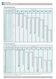
Insatallation & Operating Instructions9. Technical data9.1. EnvironmentalOperational ambient temperature range: -10 … 50°C, Frost and condensation freeStorage ambient temperature range: -40 … 60°CMaximum altitude: 2000m. De-rate above 1000m: 1% / 100mMaximum humidity: 95%, non-condensing9.2. Rating tablesPartNumber kW HP200-240V ±10% - 1 Phase Input – 3 Phase Output with Internal RFI FilterFrameSizeNominalInputCurrent(Amps)Fuse orMCB (typeB)(Amps)SupplyCableSize(mm 2 )NominalOutputCurrent(Amps)150%OutputCurrent60 secs(Amps)MotorCableSize(mm 2 )Max MotorCableLength(m)Min BrakeResistorValue572H21P5 1.5 2 2 19.3 20 4 7 10.5 1.5 100 33572H22P2 2.2 3 2 28.8 32 6 10.5 15.75 1.5 100 22(Ω)NOTEFor cUL compliance, fuse type Bussmann KTN-R / KTS-R or equivalent must be used200-240V ±10% - 3 Phase Input – 3 Phase Output with Internal RFI FilterPartNumber kW HPFrameSizeNominalInputCurrentFuse orMCB(type B)SupplyCableSizeNominalOutputCurrent150%OutputCurrent60 secsMotorCableSizeMax MotorCableLengthMinBrakeResistorValue(Amps) (Amps) (mm 2 ) (Amps) (Amps) (mm 2 ) (m) (Ω)572H31P5 1.5 2 2 9.2 16 2.5 7 10.5 1.0 100 33572H32P2 2.2 3 2 13.7 20 4 10.5 (9) 15.75 (13.5) 1.5 100 22572H33P0 3 4 3 16.1 20 4 14 21 2.5 100 15572H34P0 4 5 3 17.3 32 6 18 27 2.5 100 15572H35P5 5.5 7.5 3 25.0 40 6 25 (24) 37.5 (36) 4 100 15572H37P5 7.5 10 4 46.6 50 10 39 58.5 10 100 6572H3011 11 15 4 54.1 63 16 46 69 10 100 6572H3015 15 20 4 69.6 80 25 61 91.5 16 100 6572H3018 18.5 25 5 76.9 80 25 72 108 16 100 3572H3022 22 30 5 92.3 100 35 90 135 25 100 3572H3030 30 40 5 116.9 125 50 110 165 35 100 3572H3037 37 50 5 150.2 160 70 150 225 55 100 3572H3045 45 60 5 176.5 200 90 180 270 70 100 3NOTEValues shown in brackets are the maximum for UL applicationsFor cUL compliance, fuse type Bussmann KTN-R / KTS-R or equivalent must be used28 www.fptgroup.com Fenner is a registered Trademark of J.H Fenner & Co Limited
Insatallation & Operating Instructions380-480V±10% - 3 Phase Input – 3 Phase Output with Internal RFI FilterPartNumber kW HPFrameSizeNominalInputCurrentFuse orMCB(type B)SupplyCableSizeNominalOutputCurrent150%OutputCurrent60 secsMotorCableSizeMaxMotorCableLengthMinBrakeResistorValue(Amps) (Amps) (mm 2 ) (Amps) (Amps) (mm 2 ) (m) (Ω)572H41P5 1.5 2 2 5.4 6 1 4.1 6.2 1 100 47572H42P2 2.2 3 2 7.6 10 1.5 5.8 8.5 1.5 100 47572H44P0 4 5 2 12.4 16 2.5 9.5 14.3 1.5 100 33572H45P5 5.5 7.5 3 16.1 20 2.5 14 21 2.5 100 22572H47P5 7.5 10 3 17.3 20 4 18 27 2.5 100 22572H4011 11 15 3 25 25 4 25 (24) 37.5 (36) 4 100 22572H4015 15 20 3 32.9 32 6 30 45 6 100 22572H4018 18.5 25 4 46.6 50 10 39 58.5 10 100 12572H4022 22 30 4 54.1 63 16 46 69 10 100 12572H4030 30 40 4 69.6 80 25 61 91.5 16 100 12572H4037 37 50 4 76.9 80 25 72 108 16 100 12572H4045 45 60 5 92.3 100 35 90 135 25 100 6572H4055 55 75 5 116.9 125 50 110 165 35 100 6572H4075 75 100 5 150.2 160 70 150 225 55 100 6572H4090 90 150 5 176.5 200 90 180 270 70 100 6572H4110 110 160 6 217.2 250 120 202 303 90 100 6572H4132 132 200 6 255.7 315 120 240 360 120 100 6572H4160 160 250 6 302.4 315 170 300 450 170 100 6NOTEValues shown in brackets are the maximum for UL applicationsFor cUL compliance, fuse type Bussmann KTN-R / KTS-R or equivalent must be used9.3. Maximum supply ratings for UL compliance:Drive rating Maximum supply voltage Maximum supply short-circuit current230V ratings 0.37kW to 18.5kW 240V rms (AC) 5kA rms (AC)230V ratings 22kW to 90kW 240V rms (AC) 10kA rms (AC)400V ratings 0.75kW to 37kW 500V/600V rms (AC) 5kA rms (AC)400V ratings 45kW to 132kW 500V/600V rms (AC) 10kA rms (AC)400V ratings 160kW 500V/600V rms (AC) 18kA rms (AC)All the drives in the above table are suitable for use on a circuit capable of delivering not more than the above specified maximum short-circuitAmperes symmetrical with the specified maximum supply voltage.Fenner is a registered Trademark of J.H Fenner & Co Limited www.fptgroup.com 29
Insatallation & Operating Instructions10. Modbus Communications10.1. IntroductionThe QD:VT can be connected to a Modbus RTU network via the RJ11 connector on the front of the drive.10.2. Modbus RTU SpecificationProtocolModbus RTUError check CRCBaud rate9600bps, 19200bps, 38400bps, 57600bps, 115200bps (default)Data format 1 start bit, 8 data bits, 1 stop bit, no parity.Physical signal RS 485 (2-wire)<strong>User</strong> interface RJ11 (see section 4.4 for more information)10.3. RJ11 Connector Configuration10.4. Modbus Telegram StructureThe QD:VT supports Master / Slave Modbus RTU communications, using the 03 Read Holding Registers and 06 Write Single HoldingRegister commands. Many Master devices treat the first Register address as Register 0, therefore it may be necessary to convert the RegisterNumbers detail in section 10.5 by subtracting 1 to obtain the correct Register address.The telegram structure is as follows:-Command 03 – Read Holding RegistersCommand 06 – Write Single Holding RegisterMaster Telegram Length Slave Response Length Master Telegram Length Slave Response LengthSlave Address 1 Byte Slave Address 1 Byte Slave Address 1 Byte Slave Address 1 ByteFunction Code 03) 1 Byte Starting Address 1 Byte Function Code (06) 1 Byte Function Code (06) 1 Byte1 st Register Address 2 Bytes 1 st Register Value 2 Bytes Register Address 2 Bytes Register Address 2 BytesNo. Of Registers 2 Bytes 2 nd Register Value 2 Bytes Value 2 Bytes Register Value 2 BytesCRC Checksum 2 Bytes CRC Checksum... 2 Bytes CRC Checksum 2 Bytes CRC Checksum 2 Bytes30 www.fptgroup.com Fenner is a registered Trademark of J.H Fenner & Co Limited
Insatallation & Operating Instructions10.5. Modbus Register MapRegisterNumberPar.TypeSupportedCommands1 - R/W 03,06 Drive Control Command 0..32 - R/W 03,06Function Range ExplanationModbus Speed referenceset-point16 Bit Word.Bit 0: Low=Stop, High=Run EnableBit 1: Low=No Function, High=Fault ResetBit 2: Low=Decel Ramp 1 (P1-04), High=DecelRamp 20..20000 Set-point frequency x10, e.g. 100 = 10.0Hz3 - R/W 03,06 Torque reference 0..2000 Torque Setpoint %x10, e.g. 1000 = 100.0%4 - R/W 03,06Acceleration andDeceleration Time5 Reserved0..255 Ramp time in seconds x 10, e.g. 250 = 25 seconds6 - R 03ErrorcodeDrive statusLow Byte = Drive Error Code, see table belowHigh Byte = Drive Status as follows:-0: Drive Stopped1: Drive Running2: Drive Tripped7 R 03 Output Motor Frequency 0..20000 Output frequency in Hz x10, e.g. 100 = 10.0Hz8 R 03 Output Motor Current 0..6000Output Motor Current in Amps x10, e.g. 10 = 1.0Amps9 P0-13 R 03 Output Motor Torque 0..2000 Output Motor Torque %x10, e.g. 1000 = 100.0%10 R 03 Output Motor <strong>Power</strong> 0..3200 Output Motor <strong>Power</strong> in kW x10, e.g. 100 = 10.0kW11 - R 03 Digital input status 0..15Indicates the status of the 4 digital inputsLowest Bit = 1 Input 121 P0-01 R 03 Bipolar analogue input value 0..1000 Analogue input % of full scale x10, (1000 = 100%)22 P0-02 R 03 2 nd analogue input value 0..1000 Analogue input % of full scale x10, (1000 = 100%)40 P0-20 R 03 DC bus voltage 0..1000 DC Bus Voltage in Volts41 P0-21 R 03 Drive temperature 0..100 Drive heat-sink temperature in ºC42 P0-22 R 03 Supply voltage L1 0..660 L1 – L2 Supply Voltage43 P0-23 R 03 Supply voltage L2 0..660 L2 – L3 Supply Voltage44 P0-24 R 03 Supply voltage L3 0..660 L3 – L1 Supply Voltage45 P0-25 R 03 Estimated rotor speed Internal Speed Value46 P0-26 R 03 kWh meter 0..1000 Energy consumed in kWh47 P0-27 R 03 MWh meter 0..65535 Energy consumed in MWhFurther registers are available; see the QD:VT Advanced <strong>User</strong> <strong>Guide</strong> for details.Fenner is a registered Trademark of J.H Fenner & Co Limited www.fptgroup.com 31
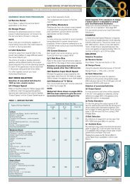
Supply Voltage- 200 – 240 Volts +/- 10%, 1 or 3 Phase- 380 – 400 Volts +/- 10%, 3 PhaseSee Page 5Fuses or MCB & Cable Sizes- Check drive rating information on page 27Keypad Operation – see page 14Control Terminal Wiring – based on default settings:-Motor Cable Sizes- Check drive rating information on page 27Motor Connections- Check for Star or Delta (see page 10)Motor Nameplate Details- Enter the motor rated voltage (V) in P1-07- Enter the motor rated current (A) in P1-08- Enter the motor rated frequency (Hz) in P1-09