Cold-Formed Steel Structures to the AISI Specification
Cold-Formed Steel Structures to the AISI Specification
Cold-Formed Steel Structures to the AISI Specification

Create successful ePaper yourself
Turn your PDF publications into a flip-book with our unique Google optimized e-Paper software.
Connections<br />
9.1 INTRODUCTION TO WELDED<br />
CONNECTIONS<br />
Welded connections between thin-walled cold-formed steel<br />
sections have become more common in recent years despite<br />
<strong>the</strong> shortage of design guidance for sections of this type.<br />
Two publications based on work at Cornell University, New<br />
York (Ref. 9.1), and <strong>the</strong> Institute TNO for Building Materials<br />
and Building <strong>Structures</strong> in Delft, Ne<strong>the</strong>rlands (Ref.<br />
9.2), have produced useful test results from which design<br />
formulae have been developed. The design rules in <strong>the</strong> <strong>AISI</strong><br />
<strong>Specification</strong> were developed from <strong>the</strong> Cornell tests.<br />
However, <strong>the</strong> more recent TNO tests add additional information<br />
<strong>to</strong> <strong>the</strong> original Cornell work, and so <strong>the</strong> results and<br />
design formulae derived in Refs. 9.1 and 9.2 are covered in<br />
this chapter even though <strong>the</strong> <strong>AISI</strong> <strong>Specification</strong> is based<br />
solely on Ref. 9.1.
Sheet steels are normally welded with conventional<br />
equipment and electrodes. However, <strong>the</strong> design of <strong>the</strong><br />
connections produced is usually different from that for<br />
hot-rolled sections and plate for <strong>the</strong> following reasons:<br />
(a) Stress-resisting areas are more difficult <strong>to</strong> define.<br />
(b) Welds such as <strong>the</strong> arc spot and seam welds in<br />
Figures 9.1c and d are made through <strong>the</strong> welded<br />
sheet without any preparation.<br />
(c)<br />
Galvanizing and paint are not normally removed<br />
prior <strong>to</strong> welding.<br />
(d) Failure modes are complex and difficult <strong>to</strong> categorize.<br />
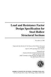
The usual types of fusion welds used <strong>to</strong> connect coldformed<br />
steel members are shown in Figure 9.1, although<br />
groove welds in butt joints may be difficult <strong>to</strong> produce in<br />
thin sheet and are <strong>the</strong>refore not as common as fillet, spot,<br />
seam, and flare groove welds. Arc spot and slot welds are<br />
commonly used <strong>to</strong> attach cold-formed steel decks and<br />
panels <strong>to</strong> <strong>the</strong>ir supporting frames. As for conventional<br />
structural welding, it is general practice <strong>to</strong> require that<br />
<strong>the</strong> weld materials be matched at least <strong>to</strong> <strong>the</strong> strength level<br />
of <strong>the</strong> weaker member. Design rules for <strong>the</strong> five weld types<br />
in Figures 9.1a-e are given as Sections E2.1-E2.5, respectively,<br />
in <strong>the</strong> <strong>AISI</strong> <strong>Specification</strong>.<br />
Failure modes in welded sheet steel are often complicated<br />
and involve a combination of basic modes, such as<br />
sheet tearing and weld shear, as well as a large amount of<br />
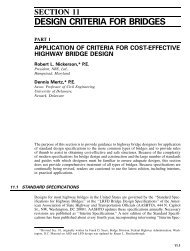
out-of-plane dis<strong>to</strong>rtion of <strong>the</strong> welded sheet. In general, fillet<br />
welds in thin sheet steel are such that <strong>the</strong> leg length on <strong>the</strong><br />
sheet edge is equal <strong>to</strong> <strong>the</strong> sheet thickness, and <strong>the</strong> o<strong>the</strong>r leg<br />
is often two <strong>to</strong> three times longer. The throat thickness (t w<br />
in Figure 9.2a) is commonly larger than <strong>the</strong> thickness (t) of<br />
<strong>the</strong> sheet steel, and, hence, ultimate failure is usually<br />
found <strong>to</strong> occur by tearing of <strong>the</strong> plate adjacent <strong>to</strong> <strong>the</strong> weld<br />
or along <strong>the</strong> weld con<strong>to</strong>ur. In most cases, yielding is poorly<br />
defined and rupture ra<strong>the</strong>r than yielding is a more reliable
FIGURE 9.1 Fusion weld types: (a) groove weld in butt joint;<br />
(b) arc spot weld (puddle weld); (c) arc seam welds; (d) fillet welds;<br />
(e) flare-bevel groove weld.
Geometry<br />
~—• -. Inclination failure<br />
^L WL'ld shear,<br />
g^-wcld tearing<br />
y & plate reaving<br />
failure<br />
modes<br />
1<br />
\ J i Sheet , J<br />
^<br />
' . — "'i<br />
^<br />
_±<br />
[ (<br />
\^<br />
^<br />
GfifuriBtry<br />
failure mode<br />
FIGURE 9.2 Transverse fillet welds: (a) single lap joint (TNO<br />
tests); (b) double lap joint (Cornell test).<br />
criterion of failure. Hence, for <strong>the</strong> fillet welds tested at<br />
Cornell University and Institute TNO, <strong>the</strong> design formulae<br />
are a function of <strong>the</strong> tensile strength (F u ) of <strong>the</strong> sheet<br />
material and not of <strong>the</strong> yield point (F y ). This latter formulation<br />
has <strong>the</strong> added advantage that <strong>the</strong> yield strength of <strong>the</strong>
cold-formed steel in <strong>the</strong> heat-affected zone does not play a<br />
role in <strong>the</strong> design and, hence, need not be determined.<br />
As a result of <strong>the</strong> different welding procedures<br />
required for sheet steel, <strong>the</strong> specification of <strong>the</strong> American<br />
Welding Society for Welding Sheet <strong>Steel</strong> in <strong>Structures</strong> (Ref.<br />
9.3) should be closely followed and has been referenced in<br />
<strong>the</strong> <strong>AISI</strong> <strong>Specification</strong>. The fact that a welder may have<br />
satisfac<strong>to</strong>rily passed a test for structural steel welding does<br />
not necessarily mean that he can produce sound welds on<br />
sheet steel. The welding positions covered by <strong>the</strong> <strong>Specification</strong><br />
are given for each weld type in Table E2 of <strong>the</strong><br />
<strong>Specification</strong>.<br />
For <strong>the</strong> welded connection in which <strong>the</strong> thickness of<br />
<strong>the</strong> thinnest connected part is greater than 0.18in., <strong>the</strong><br />
design rules in <strong>the</strong> AISC "Load and Resistance Fac<strong>to</strong>r<br />
Design for Structural <strong>Steel</strong> Buildings" (Ref. 1.1) should be<br />
used. The reason for this is that failure through <strong>the</strong> weld<br />
throat governs for thicker sections ra<strong>the</strong>r than sheet tearing<br />
adjacent <strong>to</strong> <strong>the</strong> weld in thinner sections.<br />
In <strong>the</strong> case of fillet welds and flare groove welds,<br />
failure through <strong>the</strong> weld throat is checked for plate thicknesses<br />
greater than 0.15 in. as specified in Sections E2.4<br />
and Section E2.5.<br />
9.2 FUSION WELDS<br />
9.2.1 Groove Welds in Butt Joints<br />
In <strong>the</strong> <strong>AISI</strong> <strong>Specification</strong> <strong>the</strong> nominal tensile and compressive<br />
strengths and <strong>the</strong> nominal shear strength are specified<br />
for a groove butt weld. The butt joint nominal tensile or<br />
compressive strength (P n ) is based on <strong>the</strong> yield point used<br />
in design for <strong>the</strong> lower-strength base steel and is given by<br />
P n = Lt e F y (9.1)<br />
where L is <strong>the</strong> length of <strong>the</strong> full size of <strong>the</strong> weld and t e is <strong>the</strong><br />
effective throat dimension of <strong>the</strong> groove weld. A resistance
fac<strong>to</strong>r of 0.90 is specified for LRFD and a fac<strong>to</strong>r of safety of<br />
2.5 is specified for ASD, and <strong>the</strong>y are <strong>the</strong> same as for a<br />
member.<br />
The nominal shear strength (P n ) is <strong>the</strong> lesser of <strong>the</strong><br />
shear on <strong>the</strong> weld metal given by Eq. (9.2) and <strong>the</strong> shear on<br />
<strong>the</strong> base metal given by Eq. (9.3):<br />
P n = Lt e (0.6F xx ) (9.2)<br />
(9.3)<br />
where F xx is <strong>the</strong> nominal tensile strength of <strong>the</strong> groove weld<br />
metal. A resistance fac<strong>to</strong>r of 0.8 for LRFD is used with Eq.<br />
(9.2), and a resistance fac<strong>to</strong>r of 0.9 for LRFD is used with<br />
Eq. (9.3) since it applies <strong>to</strong> <strong>the</strong> base metal. Equation (9.2)<br />
applies <strong>to</strong> <strong>the</strong> weld metal and <strong>the</strong>refore has a lower resistance<br />
fac<strong>to</strong>r than Eq. (9.3). For ASD, a fac<strong>to</strong>r of safety of 2.5<br />
is used with both equations.<br />
9.2.2 Fillet Welds Subject <strong>to</strong> Transverse<br />
Loading<br />
The Cornell test data for fillet welds, deposited from<br />
covered electrodes, was produced for <strong>the</strong> type of double<br />
lap joints shown in Figure 9.2b. These joints failed by<br />
tearing of <strong>the</strong> connected sheets along or close <strong>to</strong> <strong>the</strong> con<strong>to</strong>ur<br />
of <strong>the</strong> welds, or by secondary weld shear. Based on <strong>the</strong>se<br />
tests, Eq. (9.4) was proposed <strong>to</strong> predict <strong>the</strong> connection<br />
strength:<br />
(9.4)<br />
where t is <strong>the</strong> sheet thickness, L is <strong>the</strong> length of weld<br />
perpendicular <strong>to</strong> <strong>the</strong> loading direction, and F u is <strong>the</strong> tensile<br />
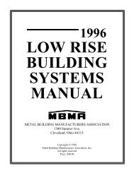
strength of <strong>the</strong> sheet. The results of <strong>the</strong>se tests are shown<br />
in Figure 9.3a for all failure modes where <strong>the</strong>y are<br />
compared with <strong>the</strong> prediction of Eq. (9.4). The values on<br />
<strong>the</strong> abscissa of Figure 9.3a are 2P n since <strong>the</strong> joints tested<br />
were double lap joints. A resistance fac<strong>to</strong>r (0) of 0.60 for<br />
256
Connections<br />
a.<br />
la<br />
10 20 30 40<br />
Theoretical Ultimate Load = 2V<br />
\ \ \<br />
40<br />
20<br />
10<br />
I<br />
0 10 20 30 40<br />
Tlisoretical Ultimate Load = 41^<br />
FIGURE 9.3 Fillet weld tests (Cornell): (a) transverse (Figure<br />
9.2b); (b) longitudinal (Figure 9.4b).
LRFD is specified for fillet welds subject <strong>to</strong> transverse<br />
loading. For ASD, a fac<strong>to</strong>r of safety of 2.5 is used. In Section<br />
E2.4 of <strong>the</strong> <strong>AISI</strong> <strong>Specification</strong>, <strong>the</strong> lesser of t l and t 2 is used<br />
<strong>to</strong> check both sheets connected by a fillet weld, where t l is<br />
for Sheet 1 and t 2 is for Sheet 2.<br />
A series of tests was performed at Institute TNO (Ref.<br />
9.2) <strong>to</strong> determine <strong>the</strong> effect of single lap joints and <strong>the</strong><br />
welding process on <strong>the</strong> strength of fillet weld connections.<br />
The joints tested are shown in Figure 9.2a and were<br />
fabricated by <strong>the</strong> TIG process for uncoated sheet and by<br />
covered electrodes for galvanized sheet. The failure modes<br />
observed were inclination failure, as shown in Figure 9.2a,<br />
combined with weld shear, weld tearing, and plate tearing.<br />
The mean test strengths (P m ) were found <strong>to</strong> be a function of<br />
<strong>the</strong> weld length <strong>to</strong> sheet width in addition <strong>to</strong> <strong>the</strong> parameters<br />
in Eq. (9.2), and are given by<br />
(9.5)<br />
Hence, for <strong>the</strong> single lap joint, <strong>the</strong> ratio L/b appears <strong>to</strong> be<br />
important.<br />
The results for galvanized sheet were found <strong>to</strong> not be<br />
significantly lower than those for uncoated sheet except<br />
that <strong>the</strong> deviation was found <strong>to</strong> be higher as a result of <strong>the</strong><br />
difficulty encountered in making a sound weld.<br />
9.2.3 Fillet Welds Subject <strong>to</strong> Longitudinal<br />
Loading<br />
The Cornell test data for fillet welds, deposited from<br />
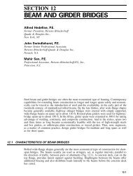
covered electrodes, was produced for <strong>the</strong> type of double<br />
lap joints shown in Figure 9.4b. These joints failed by<br />
tensile tearing across <strong>the</strong> connected sheet or by weld<br />
shear or tearing along <strong>the</strong> sheet parallel <strong>to</strong> <strong>the</strong> con<strong>to</strong>ur of<br />
<strong>the</strong> weld, as shown in Figure 9.4b. Based on <strong>the</strong>se tests, <strong>the</strong>
2P<br />
Geometry<br />
plate<br />
tearing<br />
wm . Wcki,<br />
and tearing<br />
nt weld<br />
con<strong>to</strong>ur<br />
Failure<br />
modes<br />
'I ..,..,.,....,...<br />
fj.-jjjjjjjjjjju | »jjjjjjjfjj;jjjl<br />
I<br />
t 2 >t,<br />
4P<br />
Sheet ie;ir •=<br />
I.<br />
Geometry<br />
and<br />
failure mode<br />
FIGURE 9.4 Fillet welds subject <strong>to</strong> longitudinal loading: (a) single<br />
lap joint (TNO tests); (b) double lap joint (Cornell tests).<br />
following equations were found <strong>to</strong> predict <strong>the</strong> connection<br />
strength:<br />
= tL[l -0.01-<br />
i t<br />
for - < 25<br />
(9.6)<br />
= 0.75tLF for - ^ 25<br />
(9.7)<br />
P n is <strong>the</strong> strength of a single weld. The results of all tests<br />
are shown in Figure 9.3b compared with <strong>the</strong> predictions of<br />
Eqs. (9.6) and (9.7) where <strong>the</strong> least value has been used.<br />
The values on <strong>the</strong> abscissa of Figure 9.3b are 4P n since <strong>the</strong>
joints tested were double lap joints with fillet welds on each<br />
side of each sheet.<br />
Resistance fac<strong>to</strong>rs of 0.60 and 0.55 are specified for<br />
LRFD for Eqs. (9.6) and (9.7), respectively. For ASD, a<br />
fac<strong>to</strong>r of safety of 2.5 is used. In Section E2.4 of <strong>the</strong> <strong>AISI</strong><br />
<strong>Specification</strong>, <strong>the</strong> lesser of t^ and t z is used <strong>to</strong> check both<br />
sheets connected by a fillet weld, where t l is for Sheet 1 and<br />
t 2 is for Sheet 2.<br />
A series of tests was performed more recently at Institute<br />
TNO (Ref. 9.2) <strong>to</strong> determine <strong>the</strong> effect of single lap joint<br />
geometry and welding process on <strong>the</strong> strength of fillet weld<br />
connections subject <strong>to</strong> longitudinal loading. The types of<br />
joints tested are shown in Figure 9.4a and were manufactured<br />
by <strong>the</strong> TIG process for uncoated sheet and by covered<br />
electrodes for galvanized sheet. The failure modes observed<br />
were tearing at <strong>the</strong> con<strong>to</strong>ur of <strong>the</strong> weld and weld shear<br />
accompanied by out-of-plane dis<strong>to</strong>rtion and weld peeling for<br />
short-length welds. For longer welds, plate tearing occurred.<br />
The mean test strengths (P m ) were found <strong>to</strong> be a<br />
function of <strong>the</strong> weld length (L) and sheet width (6):<br />
P m = 2*10.95 - 0.45 (9.8)<br />
P m = 0.95tbF u (9.9)<br />
The lesser of <strong>the</strong> values of Eq. (9.8) for weld failure and Eq.<br />
(9.9) for plate failure should be used. As for <strong>the</strong> transverse<br />
fillet welds, <strong>the</strong>re was no significant difference between <strong>the</strong><br />
values for <strong>the</strong> uncoated and galvanized sheets.<br />
9.2.4 Combined Longitudinal and Transverse<br />
Fillet Welds<br />
Tests were performed at Institute TNO (Ref. 9.2) <strong>to</strong> ascertain<br />
whe<strong>the</strong>r combined longitudinal and transverse fillet<br />
welds interacted adversely or beneficially. The test series<br />
showed that similar failure modes <strong>to</strong> those for longitudinal<br />
and transverse fillet welds were observed. Also, <strong>the</strong> defor-
mation capacity of <strong>the</strong> individual welds allowed full cooperation<br />
so that <strong>the</strong> strengths of <strong>the</strong> transverse and longitudinal<br />
welds can be simply added. In fact, <strong>the</strong> combined<br />
welds were better than <strong>the</strong> sum of <strong>the</strong> two, but <strong>the</strong> additional<br />
benefits have not been quantified.<br />
9.2.5 Flare Groove Welds<br />
Flare welds are of two common types. These are flare-bevel<br />
welds, as shown in Figure 9.1e and in cross section in<br />
Figure 9.5a, and flare V-welds, as shown in cross section<br />
in Figure 9.5b.<br />
As for fillet welds, <strong>the</strong> flare welds may be loaded<br />
transversely or longitudinally, and <strong>the</strong>ir modes of failure<br />
are similar <strong>to</strong> fillet welds described in Sections 9.2.2 and<br />
9.2.3. The primary mode of failure is sheet tearing along<br />
<strong>the</strong> weld con<strong>to</strong>ur.<br />
For transverse flare-bevel groove welds, <strong>the</strong> nominal<br />
shear strength in Section E2.5 of <strong>the</strong> <strong>AISI</strong> <strong>Specification</strong> is<br />
<strong>the</strong> same as for a fillet weld subject <strong>to</strong> transverse loading<br />
[Eq. (9.4)] except that it is fac<strong>to</strong>red by 5/6 = 0.833:<br />
P n = 0.833tLF u<br />
(9.10)<br />
Lip<br />
height<br />
h<br />
~<br />
\V-j_<br />
i<br />
T<br />
—.— i ————0-r<br />
1/2 in,)<br />
FIGURE 9.5 Flare groove weld cross sections: (a) flare-bevel<br />
groove weld; (b) flare V-groove weld.
The resistance fac<strong>to</strong>r <strong>to</strong> be used in LRFD with Eq. (9.10) is<br />
(p = 0.55. For ASD a fac<strong>to</strong>r of safety of 2.5 is used.<br />
For flare groove welds subject <strong>to</strong> longitudinal loading,<br />
ei<strong>the</strong>r on a flare-bevel groove weld as in Figure 9.5a or a<br />
flare V-groove weld as in Figure 9.5b, <strong>the</strong> nominal shear<br />
strength depends on <strong>the</strong> effective throat thickness (t w ) of<br />
<strong>the</strong> flare weld and <strong>the</strong> lip height (h) in Figure 9.5a. If<br />
t ^ t w < 2t or <strong>the</strong> lip height (h) is less than <strong>the</strong> weld length<br />
(L), <strong>the</strong> nominal strength is <strong>the</strong> same for a fillet weld<br />
subject <strong>to</strong> longitudinal loading given by Eq. (9.7), so that<br />
P n = 0.75tLF u (9.11)<br />
If t w ^ 2t and h ^ L, <strong>the</strong>n<br />
P u = l.5tLF u (9.12)<br />
The resistance fac<strong>to</strong>r <strong>to</strong> be used in both cases in LRFD is<br />
0.55, and <strong>the</strong> fac<strong>to</strong>r of safety in ASD is 2.5.<br />
In <strong>the</strong> <strong>AISI</strong> <strong>Specification</strong>, Section E2.5 defines t w for a<br />
range of cases including flare groove welds filled flush <strong>to</strong><br />
surface and flare groove welds not filled flush <strong>to</strong> surface, as<br />
shown in Figure 9.5. For t > 0.15 in., failure through <strong>the</strong><br />
throat thickness t ll} is checked based on <strong>the</strong> weld metal<br />
strength of F x<br />
"w<br />
XX'<br />
9.2.6 Arc Spot Welds (Puddle Welds)<br />
Arc spot welds are for welding sheet steel <strong>to</strong> thicker<br />
supporting members in a flat position. Arc spot welds<br />
have three different diameters at different levels of <strong>the</strong><br />
weld, as shown in Figure 9.6a for a single thickness of<br />
attached sheet and in Figure 9.6b for a double thickness of<br />
attached sheet. The diameter d is <strong>the</strong> visible width of <strong>the</strong><br />
arc spot weld, <strong>the</strong> diameter d a is <strong>the</strong> average diameter at<br />
mid-thickness, and <strong>the</strong> diameter d e is <strong>the</strong> effective diameter<br />
of <strong>the</strong> fused area. In general, arc-spot-welded connections<br />
are applied in sheet steel with thicknesses from about<br />
0.02 in. <strong>to</strong> 0.15 in. Weld washers must be used when <strong>the</strong><br />
thickness of <strong>the</strong> sheet is less than 0.028 in. In many ways,
<strong>the</strong> design of an arc spot weld is similar <strong>to</strong> an equivalent<br />
bolted connection since <strong>the</strong> failure modes are similar <strong>to</strong><br />
those of mechanical connections. The principal modes of<br />
failure are shown in Figure 9.7. Only <strong>the</strong> mode shown in<br />
(b), tearing and bearing at weld con<strong>to</strong>ur, does not have an<br />
exact equivalent in bolted connection design.<br />
The Cornell test data for spot welds is shown in Figure<br />
9.8a. Those joints which failed by weld shear, as shown in<br />
Figure 9.7e, were used <strong>to</strong> determine <strong>the</strong> effective diameter<br />
(d e ) of <strong>the</strong> fused area:<br />
d e = O.lOd - 1.5* < 0.55d (9.13)<br />
The minimum allowable value of d p K is f in.<br />
o<br />
Weld shear failure loads can be successfully predicted<br />
by<br />
V w =^(d e f0.75F xx (9.14)<br />
where F xx is <strong>the</strong> filler metal strength for <strong>the</strong> AWS Electrode<br />
Classification. A resistance fac<strong>to</strong>r of 0.60 for LRFD is<br />
specified in <strong>the</strong> <strong>AISI</strong> <strong>Specification</strong> for use with Eq. (9.14).<br />
For ASD a fac<strong>to</strong>r of safety of 2.5 is used.<br />
For plate tearing around <strong>the</strong> weld, as shown in Figure<br />
9.7b, <strong>the</strong> following formulae for <strong>the</strong> nominal shear strength<br />
of an arc spot weld have been developed:<br />
and<br />
P n = 2.2td a F u for ^ < 0.815 /^ (9.15)<br />
t \l *u<br />
P n = lAtd a F u for > 1.397 - (9.16)<br />
P n = 0.280<br />
djt<br />
in <strong>the</strong> transition region (9.17)
da = [1 - i iJ, = d 21<br />
•'<br />
t^-i<br />
———U-<br />
FIGURE 9.6 Arc spot and arc seam weld geometry: (a) single<br />
thickness of sheet; (b) double thickness of sheet; (c) minimum<br />
edge distance (arc spot welds); (d) geometry and minimum edge<br />
distance (arc seam welds).<br />
where d a is <strong>the</strong> average diameter of <strong>the</strong> arc spot weld, F u is<br />
<strong>the</strong> tensile strength of <strong>the</strong> sheet material, and t is <strong>the</strong> <strong>to</strong>tal<br />
combined sheet thickness of steels involved in shear transfer<br />
above <strong>the</strong> plane of maximum shear transfer. The value<br />
of d a is d — t for a single sheet and d — 2t for multiple<br />
sheets.<br />
The results of all of <strong>the</strong> tests are shown in Figure 9.8a<br />
compared with <strong>the</strong> predictions of Eqs. (9.13)-(9.19) where<br />
<strong>the</strong> least value has been used. The values on <strong>the</strong> abscissa of<br />
Figure 9.8a are 2P n since <strong>the</strong> joints tested were double lap<br />
joints. The variability of <strong>the</strong> test results in Figure 9.8a<br />
occurred because all of <strong>the</strong> field-welded specimens were<br />
poorly made. Resistance fac<strong>to</strong>rs in LRFD of 0.60, 0.50, 0.50<br />
apply <strong>to</strong> Eqs. (9.15)-(9.17), respectively, as specified in<br />
Section E2.2.1 of <strong>the</strong> <strong>AISI</strong> <strong>Specification</strong>. For ASD a fac<strong>to</strong>r<br />
of safety of 2.5 is used throughout.<br />
The failure mode of net section failure shown in Figure<br />
9.7d must be checked separately by using <strong>the</strong> net section<br />
capacity of a tension member as given by Section C2 of <strong>the</strong><br />
<strong>AISI</strong> <strong>Specification</strong>. For <strong>the</strong> purpose of this calculation, <strong>the</strong><br />
net section is <strong>the</strong> full section width (b) of <strong>the</strong> plate.
(a)<br />
Sheet __4^[ .=<br />
tear " I v*<br />
i<br />
Buckled<br />
plate<br />
{b)<br />
(e)<br />
FIGURE 9.7 Failure modes in arc spot welds: (a) inclination<br />
failure; (b) tearing and bearing at weld con<strong>to</strong>ur; (c) edge failure;<br />
(d) net section failure; (e) weld shear failure.<br />
The failure mode of edge failure shown in Figure 9.7c<br />
is limited in Section E2.2.1 of <strong>the</strong> <strong>AISI</strong> <strong>Specification</strong> by<br />
limiting <strong>the</strong> edge distance. The minimum distance e min<br />
from <strong>the</strong> centerline of a weld <strong>to</strong> <strong>the</strong> nearest edge of an<br />
adjacent weld or <strong>the</strong> end of <strong>the</strong> connected point <strong>to</strong>ward<br />
which <strong>the</strong> force is directed is<br />
for LRFD (9.18)
(a)<br />
40<br />
30<br />
H)<br />
0 10 20 30 40<br />
Theoretical Ultimate Load = ?,?„<br />
(h)<br />
40<br />
30<br />
21)<br />
10<br />
o in 20 10 40<br />
Theoretical Ultimate Load = 21^<br />
FIGURE 9.8 Arc spot and arc seam weld tests (Cornell): (a) arc<br />
spot welds; (b) arc seam welds.
where P u is <strong>the</strong> required strength (fac<strong>to</strong>red) transmitted by<br />
<strong>the</strong> weld.<br />
(9.19)<br />
where P is <strong>the</strong> required strength (unfac<strong>to</strong>red) transmitted<br />
by <strong>the</strong> weld. In Eqs. (9.18) and (9.19), t is <strong>the</strong> thickness of<br />
<strong>the</strong> thinnest connected sheet. The values of resistance<br />
fac<strong>to</strong>r (0) and fac<strong>to</strong>r of safety (Q) depend on <strong>the</strong> ratio of<br />
F u /F sy \ when it is less than 1.08, 0 and Q are 0.70 and 2.0,<br />
respectively; o<strong>the</strong>rwise <strong>the</strong>y are 0.60 and 2.22, respectively.<br />
Arc spot welds in tension are specified in Section<br />
E2.2.2 of <strong>the</strong> <strong>AISI</strong> <strong>Specification</strong>. Ei<strong>the</strong>r weld failure or<br />
sheet tear around <strong>the</strong> weld can occur. For weld failure,<br />
<strong>the</strong> nominal tensile strength (P n ) of each concentrically<br />
loaded arc spot weld is given by<br />
P n =\dlF xx (9.20)<br />
such that F xx is <strong>the</strong> filler metal strength, which must be<br />
greater than GOksi and F u . For sheet tear <strong>the</strong> nominal<br />
tensile strength (P n ) of each concentrically loaded arc spot<br />
weld is given by<br />
P n = 6.59 - 3150F,, td a F u < lA6tdaF u<br />
for F u < 0.00187E (9.21)<br />
P n = 0.70td a F u for F u ^ 0.00187E (9.22)<br />
where F,. ^ 82 ksi. The values of resistance fac<strong>to</strong>r for LRFD<br />
lA/<br />
and safety fac<strong>to</strong>r for ASD are 0.60 and 2.50, respectively.<br />
Fur<strong>the</strong>r, if eccentric loading can be applied <strong>to</strong> <strong>the</strong> arc spot<br />
weld, <strong>the</strong>n it is prudent <strong>to</strong> reduce <strong>the</strong> tensile capacity of an<br />
arc spot weld <strong>to</strong> 50% of <strong>the</strong> values given by Eqs. (9.20)-<br />
(9.22).
9.2.7 Arc Seam Welds<br />
Arc seam welds commonly find application in <strong>the</strong> narrow<br />
troughs of cold-formed steel decks and panels. The geometry<br />
of an arc seam weld is shown in Figure 9.6d. The<br />
observed behavior of <strong>the</strong> arc seam welds tested at Cornell<br />
was similar <strong>to</strong> <strong>the</strong> arc spot welds, although no simple shear<br />
failures were observed. The major mode of failure was<br />
tensile tearing of <strong>the</strong> sheets along <strong>the</strong> forward edge of <strong>the</strong><br />
weld con<strong>to</strong>ur plus shearing of <strong>the</strong> sheets along <strong>the</strong> sides of<br />
<strong>the</strong> weld. The full set of test results for <strong>the</strong> arc welds is<br />
shown in Figure 9.8b. In general, <strong>the</strong>re was considerably<br />
less variability than for <strong>the</strong> arc spot welds shown in Figure<br />
9.8a.<br />
Based on <strong>the</strong> Cornell tests, <strong>the</strong> following formula has<br />
been developed for arc seam welds:<br />
P n = 2.5tF u (0.25L + 0.96d a ) (9-23)<br />
where d a is <strong>the</strong> width of <strong>the</strong> arc seam weld as discussed in<br />
Section 9.2.6. The test results plotted in Figure 9.8b are<br />
compared with <strong>the</strong> prediction of Eq. (9.23). The values on<br />
<strong>the</strong> abscissa of Figure 9.8b are 2P n since <strong>the</strong> joints tested<br />
were double lap joints. A resistance fac<strong>to</strong>r of 0.60 is specified<br />
for LRFD for use with Eq. (9.23). The fac<strong>to</strong>r of safety<br />
for ASD is 2.50.<br />
In addition, <strong>the</strong> <strong>AISI</strong> <strong>Specification</strong> includes a formula<br />
<strong>to</strong> check <strong>the</strong> shear capacity of <strong>the</strong> weld:<br />
(9.24)<br />
where F xx is <strong>the</strong> filler metal strength in <strong>the</strong> AWS electrode<br />
classification.<br />
The minimum edge distance (e min ) shown in Figure<br />
9.6d is <strong>the</strong> same as specified for arc spot welds described by<br />
Eqs. (9.18) and (9.19).
9.3 RESISTANCE WELDS<br />
Resistance welds are a type of arc spot weld and, as such,<br />
may fail in shear. The nominal shear capacities (P n ) of<br />
resistance spot welds specified in Table E2.6 of <strong>the</strong> <strong>AISI</strong><br />
<strong>Specification</strong> were simply taken from Ref. 9.4. A resistance<br />
fac<strong>to</strong>r of 0.65 is specified for LRFD in Section E2.6 of <strong>the</strong><br />
<strong>AISI</strong> <strong>Specification</strong>. Welding shall be performed in accordance<br />
with AWS Cl.3-70 (Ref. 9.4) and AWS Cl.1-66<br />
(Ref. 9.5) and <strong>the</strong> <strong>AISI</strong> <strong>Specification</strong>, and a fac<strong>to</strong>r of<br />
safety of 2.5 is specified for ASD.<br />
By comparison, <strong>the</strong> approach developed at <strong>the</strong> Institute<br />
TNO (Ref. 9.2) uses <strong>the</strong> same design formulae for<br />
resistance welds as for arc spot welds but with a different<br />
formula for <strong>the</strong> effective weld diameter from that for arc<br />
spot welds.<br />
9.4 INTRODUCTION TO BOLTED<br />
CONNECTIONS<br />
Bolted connections between cold-formed steel sections<br />
require design formulae different from those of hot-rolled<br />
construction, as a result of <strong>the</strong> smaller ratio of sheet<br />
thickness <strong>to</strong> bolt diameter in cold-formed design. The<br />
design provisions for bolted connections in <strong>the</strong> <strong>AISI</strong> <strong>Specification</strong><br />
are based mainly on Ref. 9.6.<br />
The <strong>AISI</strong> <strong>Specification</strong> allows use of bolts, nuts, and<br />
washers <strong>to</strong> <strong>the</strong> following ASTM specifications.<br />
ASTM A194/A194M Carbon and Alloy <strong>Steel</strong> Nuts for<br />
Bolts for High- Pressure and High-Temperature<br />
Service<br />
ASTM A307 (Type A) Carbon <strong>Steel</strong> Bolts and Studs,<br />
60,000 PSI Tensile Strength<br />
ASTM A325 Structural Bolts, <strong>Steel</strong>, Heat Treated,<br />
120/150 ksi Minimum Tensile Strength<br />
ASTM A325M High Strength Bolts for Structural<br />
<strong>Steel</strong> Joints [metric]
ASTM A354 (Grade BD) Quenched and Tempered<br />
Alloy <strong>Steel</strong> Bolts, Studs, and O<strong>the</strong>r Externally<br />
Threaded Fasteners (for diameter of bolt smaller<br />
than \ in.)<br />
ASTM A449 Quenched and Tempered <strong>Steel</strong> Bolts and<br />
Studs (for diameter of bolt smaller than \ in.)<br />
ASTM A490 Heat-Treated <strong>Steel</strong> Structural Bolts,<br />
150 ksi Minimum Tensile Strength<br />
ASTM A490M High Strength <strong>Steel</strong> Bolts, Classes<br />
10.9 and 10.9.3, for Structural <strong>Steel</strong> Joints [metric]<br />
ASTM A563 Carbon and Alloy <strong>Steel</strong> Nuts<br />
ASTM A563M Carbon and Alloy <strong>Steel</strong> Nuts [metric]<br />
ASTM F436 Hardened <strong>Steel</strong> Washers<br />
ASTM F436M Hardened <strong>Steel</strong> Washers [metric]<br />
ASTM F844 Washers, <strong>Steel</strong>, Plain (Flat), Unhardened<br />
for General Use<br />
ASTM F959 Compressible Washer-Type Direct<br />
Tension Indica<strong>to</strong>rs for Use with Structural Fasteners<br />
ASTM F959M Compressible Washer-Type Direct<br />
Tension Indica<strong>to</strong>rs for Use with Structural Fasteners<br />
[metric]<br />
Bolts manufactured according <strong>to</strong> ASTM A307 have a<br />
nominal tensile strength of 60 ksi. The standard size<br />
range denned in A307 is from | <strong>to</strong> |in. in yg-in. increments.<br />
Bolts manufactured according <strong>to</strong> ASTM A325 and ASTM<br />
A449 have a nominal tensile strength of 120 ksi and a<br />
nominal 0.2% proof stress of 92 ksi. The standard size<br />
range denned in ASTM A325 is | <strong>to</strong> |in. in yg-in. increments;<br />
in ASTM A449 <strong>the</strong> range is |in. <strong>to</strong> ygin. in yg-in.<br />
increments. The design rules in <strong>the</strong> <strong>AISI</strong> <strong>Specification</strong> only<br />
apply when <strong>the</strong> thickness of a connected part is less than<br />
ygin. For connected parts y|in. or greater, <strong>the</strong> AISC <strong>Specification</strong><br />
(Ref. 1.1) should be used.<br />
A selection of bolted connections, where <strong>the</strong> bolts are<br />
principally in shear, is shown in Figure 9.9. As shown in
s<br />
c<br />
)<br />
CMjo<br />
i<br />
1.5d 3d<br />
(Minimum values)<br />
(b)<br />
s/2<br />
s<br />
rf\ M<br />
*^ ——T*<br />
s/2<br />
— - ——<br />
———<br />
(c)<br />
C<br />
FIGURE 9.9 Bolted connection geometry: (a) single bolt (r — 1); (b)<br />
three bolts in line of force (r — |); (c) two bolts across line of force<br />
(r — 1); (d) double shear (with washers); (e) single shear (with<br />
washers).
this figure, <strong>the</strong> bolts may be located in line with <strong>the</strong> line of<br />
action of <strong>the</strong> force (Figure 9.9b) or perpendicular <strong>to</strong> <strong>the</strong> line<br />
of action of <strong>the</strong> force (Figure 9.9c) or both simultaneously.<br />
The connections may be in double shear with a cover plate<br />
on each side, as in Figure 9.9d, or in single shear, as in<br />
Figure 9.9e. In addition, each bolt may contain washers<br />
under <strong>the</strong> head and nut, under <strong>the</strong> nut alone, or under<br />
nei<strong>the</strong>r.<br />
The symbols e for edge distance or distance <strong>to</strong> an<br />
adjacent bolt hole, s for bolt spacing perpendicular <strong>to</strong> <strong>the</strong><br />
line of stress, and d for bolt diameter are shown for <strong>the</strong><br />
various bolted connection geometries in Figures 9.9a—c. In<br />
Table E3, <strong>the</strong> <strong>AISI</strong> <strong>Specification</strong> defines <strong>the</strong> diameter of a<br />
standard hole (d h ) as yg in. larger than <strong>the</strong> bolt diameter (d)<br />
for bolt diameters |in. and larger and ^in. larger than <strong>the</strong><br />
bolt diameter for bolts less than |in. diameter. Oversized<br />
holes, short-slotted holes, and long-slotted holes are also<br />
defined in Table E3.<br />
9.5 DESIGN FORMULAE AND FAILURE<br />
MODES FOR BOLTED CONNECTIONS<br />
The four principal modes of failure for bolted connections of<br />
<strong>the</strong> types in Figure 9.9 are shown in Figure 9.10. They have<br />
been classified in Ref. 9.6 as Types I, II, III, and IV. This<br />
classification has been followed in this book.<br />
9.5.1 Tearout Failure of Sheet (Type I)<br />
For sheets which have a small distance (e) from <strong>the</strong> bolt <strong>to</strong><br />
<strong>the</strong> edge of <strong>the</strong> plate or an adjacent hole where <strong>the</strong> distance<br />
is taken in <strong>the</strong> direction of <strong>the</strong> line of action of <strong>the</strong> force,<br />
sheet tearing along two lines as shown in Figure 9.10a can<br />
occur. Using <strong>the</strong> tests summarized in Ref. 9.6, <strong>the</strong> following<br />
relationship has been developed <strong>to</strong> predict tearout failure:<br />
§" ± = u3<br />
(9 ' 25)
Tear<br />
(a)<br />
Buckled<br />
plats<br />
i<br />
i<br />
(h)<br />
Tl'ar<<br />
(c)<br />
FIGURE 9.10 Failure modes of bolted connections: (a) tearout<br />
failure of sheet (Type I); (b) bearing failure of sheet material<br />
(Type II); (c) tension failure of net section (Type III); (d) shear<br />
failure of bolt (Type IV).<br />
where F bu is <strong>the</strong> bearing stress between <strong>the</strong> bolt and sheet<br />
at tearout failure. Equation (9.25) is compared with <strong>the</strong><br />
tests on bolted connections in single shear (with and without<br />
washers) in Figure 9.11. Additional graphs of test<br />
results for double shear are given in Ref. 9.6. In all cases,<br />
Eq. (9.25) adequately predicts failure for low values of <strong>the</strong><br />
ratio e/d.<br />
Letting F bu = PJdt in Eq.(9.25) results in<br />
P n = (9.26)
o o<br />
0<br />
3 4<br />
etd<br />
Failure '.type<br />
a I<br />
° II<br />
* I tind II<br />
i II and in<br />
1.08<br />
0<br />
Failure'I<br />
o I<br />
A<br />
*<br />
II<br />
I and II<br />
1 2 3 4 5 6 7<br />
c/d<br />
ib)<br />
FIGURE 9.11 Bolted connection tests (tearout and bearing failures):<br />
(a) single shear connections with washers; (b) single shear<br />
connections without washers.
The resistance fac<strong>to</strong>r (0) (LRFD) or fac<strong>to</strong>r of safety (Q)<br />
(ASD) for use with P n specified in Section E3.1 of <strong>the</strong> <strong>AISI</strong><br />
<strong>Specification</strong> depends on <strong>the</strong> ratio of tensile stress <strong>to</strong> yield<br />
stress of <strong>the</strong> steel, so that<br />
0 = 0.70 for ZL ^ 1.08 (9.27)<br />
sy<br />
Q = 2.0<br />
0 = 0.60 for -^ < 1.08 (9.28)<br />
sy<br />
Q = 2.22<br />
In addition, <strong>the</strong> <strong>AISI</strong> <strong>Specification</strong> specifies a minimum<br />
distance between bolt holes of not less than 3d and a<br />
minimum distance from <strong>the</strong> center of any standard hole<br />
<strong>to</strong> <strong>the</strong> end boundary of a connecting member as 1.5d.<br />
9.5.2 Bearing Failure of Sheet (Type II)<br />
For bolted connections where <strong>the</strong> edge distance is sufficiently<br />
large, <strong>the</strong> bearing stress at failure (F bu ) is no longer<br />
a function of edge distance (e) and bearing failure of <strong>the</strong><br />
sheet (Figure 9.10b) may occur. The test results shown in<br />
Figure 9.11 demonstrate <strong>the</strong> independence of F^u from e for<br />
larger values of e. For <strong>the</strong> cases of single shear connections<br />
with and without washers, <strong>the</strong> bearing stress at ultimate is<br />
shown <strong>to</strong> be a function of whe<strong>the</strong>r washers are installed<br />
and <strong>the</strong> ratio of F u /F sy . Additional graphs in Ref. 9.6<br />
demonstrate a similar dependence for double-shear connections<br />
with and without washers. Hence, <strong>the</strong> inclusion of<br />
washers under both bolt head and nut is important in <strong>the</strong><br />
design of bolted connections in cold-formed steel, probably<br />
as a result of <strong>the</strong> low sheet thicknesses in cold-formed<br />
design.<br />
From Figure 9. Ha <strong>the</strong> nominal bearing capacity for<br />
single shear with washers and F u /F sy < 1.08 is<br />
P n = 3.00F u dt (9.29)
The resistance fac<strong>to</strong>r for use in LRFD with Eq. (9.29) is<br />
specified in Table E3.3-1 of <strong>the</strong> <strong>AISI</strong> <strong>Specification</strong> as 0.60,<br />
and <strong>the</strong> fac<strong>to</strong>r of safety for use in ASD is 2.22. O<strong>the</strong>r cases,<br />
based on <strong>the</strong> tests summarized in Ref. 9.6, are set out in<br />
Tables E3.3-1 and E3.3-2 of <strong>the</strong> <strong>AISI</strong> <strong>Specification</strong>.<br />
Recent research has been performed at <strong>the</strong> University<br />
of Sydney by Rogers and Hancock (Ref. 9.7) on bolted<br />
connections of thin G550 (SOksi) and G300 (44ksi) sheet<br />
steels in 0.42-mm (0.016 in.) and 0.60-mm (0.024in.) base<br />
metal thickness. The test results indicate that <strong>the</strong> connection<br />
provisions described above cannot be used <strong>to</strong> accurately<br />
predict <strong>the</strong> failure mode of bolted connections from<br />
thin G550 and G300 steels. Fur<strong>the</strong>rmore, <strong>the</strong> design rules<br />
cannot be used <strong>to</strong> accurately determine <strong>the</strong> bearing resistance<br />
of bolted test specimens based on a failure criterion<br />
for predicted loads. It is necessary <strong>to</strong> incorporate a variable<br />
resistance equation which is dependent on <strong>the</strong> thickness of<br />
<strong>the</strong> connected material similar <strong>to</strong> CAN/CSA-S136-94 (Ref.<br />
1.6). In addition, <strong>the</strong> ultimate bearing stress <strong>to</strong> ultimate<br />
material strength ratios show that a bearing equation<br />
coefficient of less than 2.0 in Eq. (9.29) may be appropriate<br />
for G550 sheet steels where d/t ^ 15.<br />
9.5.3 Net Section Tension Failure (Type III)<br />
If <strong>the</strong> stresses in <strong>the</strong> net section are <strong>to</strong>o high, tension<br />
failure of <strong>the</strong> net section, as shown in Figure 9.10c, may<br />
occur before tearout or bearing failure of <strong>the</strong> sheet. The<br />
stresses in <strong>the</strong> net section are dependent upon stress<br />
concentrations adjacent <strong>to</strong> <strong>the</strong> bolt holes and hence are a<br />
function of <strong>the</strong> bolt spacing (s) and <strong>the</strong> number of bolts, in<br />
addition <strong>to</strong> <strong>the</strong> net area and <strong>the</strong> load in <strong>the</strong> section.<br />
Consequently, empirical formulae have been developed <strong>to</strong><br />
relate <strong>the</strong> stress in <strong>the</strong> net section <strong>to</strong> <strong>the</strong> above parameters.<br />
For <strong>the</strong> case of bolts in single shear, <strong>the</strong> test results<br />
summarized in Ref. 9.6 are shown in Figure 9.12a for<br />
connections with washers, and in Figure 9.12b for connec-
1.6<br />
1.2<br />
F,,<br />
n<br />
hi<br />
--^f<br />
=(l-0.9n-3r(d/*)<br />
0/1<br />
_|____________|_<br />
o One<br />
Bolts a<br />
Q Three<br />
0 0.1 0.2 0.3 0.4 0.5 0.6<br />
L6<br />
] T^ \ ST<br />
O<br />
O<br />
1.2<br />
I'u<br />
0.8<br />
^c = {I-r+2.5r(d/s))<br />
0.4<br />
o One<br />
Bolls •[ i Two<br />
a Three<br />
i______i_____<br />
0 0,1 0.2 0.4 0,6<br />
d/s<br />
(b)<br />
FIGURE 9.12 Bolted connection tests (net section failures): (a)<br />
single shear with washers; (b) single shear without washers.
tions without washers. The resulting empirical formulae<br />
for <strong>the</strong> nominal tension strength (P n ) are<br />
With washers<br />
P n =(l- 0.9r + —— \F u A n < F u A n<br />
V<br />
s /<br />
(9.30)<br />
No washers P n =(l-r+ < (9.31)<br />
where r is <strong>the</strong> ratio of <strong>the</strong> force transmitted by <strong>the</strong> bolt or<br />
bolts at <strong>the</strong> section considered divided by <strong>the</strong> tension force<br />
in <strong>the</strong> full cross section at that section. The effect of varying<br />
r by changing <strong>the</strong> number of bolts at a cross section is<br />
clearly demonstrated in Figure 9.12. It is interesting <strong>to</strong><br />
observe that a larger number of bolts in <strong>the</strong> line of <strong>the</strong> force<br />
reduces <strong>the</strong> stress concentration and hence increases <strong>the</strong><br />
load capacity on a given net area.<br />
The resistance fac<strong>to</strong>r (0) for use in LRFD and <strong>the</strong><br />
fac<strong>to</strong>r of safety (Q) for use in ASD with P n specified in<br />
Section E3.2 of <strong>the</strong> <strong>AISI</strong> <strong>Specification</strong> depend on whe<strong>the</strong>r<br />
<strong>the</strong> connection is double or single shear and whe<strong>the</strong>r<br />
washers are included, as follows:<br />
With washers (double shear) 0 = 0.65, Q = 2.0<br />
and no washers (9.32)<br />
With washer (single shear) 0 = 0. 55, Q = 2.22<br />
(9.33)<br />
Based on Ref. 9.7, <strong>the</strong> net section failure of 0.42-mm<br />
(0.016 in.) and 0.60-mm (0.024 in.) G550 (SOksi) and G300<br />
(44ksi) sheet steels at connections can be accurately and<br />
reliably predicted with <strong>the</strong> use of <strong>the</strong> stress reduction fac<strong>to</strong>r<br />
based on <strong>the</strong> configuration of bolts and specimen width as<br />
given by Eqs. (9.30) and (9.31), and without <strong>the</strong> use of <strong>the</strong>
75% stress reduction fac<strong>to</strong>r as specified in Section A3.3.2 of<br />
<strong>the</strong> <strong>AISI</strong> <strong>Specification</strong> for Grade 80 and Grade E steels.<br />
9.5.4 Shear Failure of Bolt (Type IV)<br />
The nominal shear strength (P n ) of a bolt specified in<br />
Section E3.4 of <strong>the</strong> <strong>AISI</strong> <strong>Specification</strong> is given by<br />
P n =A b F nv (9.34)<br />
where F nv is given in Table E3.4-1 of <strong>the</strong> <strong>AISI</strong> <strong>Specification</strong><br />
A b is <strong>the</strong> gross cross-sectional area of <strong>the</strong> bolt<br />
The value of F nv depends upon whe<strong>the</strong>r threads are<br />
excluded from <strong>the</strong> shear plane. The resistance fac<strong>to</strong>r for<br />
LRFD specified in Table E3.4-1 of <strong>the</strong> <strong>AISI</strong> <strong>Specification</strong> is<br />
0.65, and <strong>the</strong> fac<strong>to</strong>r of safety for ASD is 2.4.<br />
The nominal tension strength (P n ) of a bolt specified in<br />
Section E3.4 of <strong>the</strong> <strong>AISI</strong> <strong>Specification</strong> is<br />
P n =A b F nt (9.35)<br />
where F nt is given in Table E3.4-1 of <strong>the</strong> <strong>AISI</strong> <strong>Specification</strong><br />
A b is <strong>the</strong> gross cross-sectional area of <strong>the</strong> bolt<br />
The resistance fac<strong>to</strong>r for LRFD specified in Table E3.4-1 of<br />
<strong>the</strong> <strong>AISI</strong> <strong>Specification</strong> is 0.75, and <strong>the</strong> fac<strong>to</strong>r of safety for<br />
ASD is generally 2.0, although 2.25 is used for ASTM A307<br />
bolts.<br />
When a combination of shear and tension occurs, <strong>the</strong><br />
value ofF nt in Eq. (9.35) is changed <strong>to</strong> F' nt . Value of F' nt are<br />
given in Tables E3.4-3 and E3.4-5 for LRFD and E3.4-2 and<br />
E3.4-4 for ASD. They take <strong>the</strong> form<br />
F' nt = 101 - 2Af D < 81 ksi (9.36)<br />
which is <strong>the</strong> equation for an ASTM A449 bolt designed by<br />
LRFD with threads not excluded from <strong>the</strong> shear plane, with<br />
f v equal <strong>to</strong> <strong>the</strong> shear stress.
9.6 SCREW FASTENERS<br />
Screw fasteners are used very frequently in cold-formed<br />
steel structures, normally <strong>to</strong> fasten sheeting <strong>to</strong> thicker<br />
material such as purlins, or <strong>to</strong> fasten sheets <strong>to</strong>ge<strong>the</strong>r. A<br />
considerable amount of information is available in <strong>the</strong><br />
international literature and has been used <strong>to</strong> develop<br />
Section E4, Screw Connections of <strong>the</strong> <strong>AISI</strong> <strong>Specification</strong>.<br />
The ECCS document European Recommendations for<br />
<strong>the</strong> Design of Light Gauge <strong>Steel</strong> Members (Ref. 9.8) was <strong>the</strong><br />
first <strong>to</strong> provide detailed guidance on <strong>the</strong> design of screw<br />
fasteners and blind rivets. The background research <strong>to</strong> this<br />
document is set out in Ref. 9.9. Fur<strong>the</strong>r developments of <strong>the</strong><br />
European design rules have been performed <strong>to</strong> produce <strong>the</strong><br />
design requirements in Eurocode 3 Part 1.3 (Ref. 1.7). In<br />
order <strong>to</strong> apply <strong>the</strong> methods developed for screwed connections<br />
in Ref. 9.8 <strong>to</strong> U.S. practice, Pekoz (Ref 9.10) modified<br />
<strong>the</strong> formulae and recalibrated <strong>the</strong> results <strong>to</strong> develop specific<br />
design rules for use in <strong>the</strong> American Iron and <strong>Steel</strong> Institute<br />
<strong>Specification</strong>. The results are based on a study of screw<br />
diameters ranging from 0.11 in. <strong>to</strong> 0.28 in. In <strong>the</strong> study, if<br />
materials of different thickness were connected, <strong>the</strong> thinner<br />
material was assumed <strong>to</strong> be in contact with <strong>the</strong> head of<br />
<strong>the</strong> screw. Two different sets of formulae are provided.<br />
These are<br />
1. Design for shear<br />
2. Design for tension<br />
2.1 Pullout failure<br />
2.2 Pullover failure<br />
Screw connections loaded in shear can fail in one mode or<br />
in a combination of modes, including screw shear, edge<br />
tearing, tilting, and subsequent pullout of <strong>the</strong> screw and<br />
bearing of <strong>the</strong> parent plates. The formulae developed only<br />
apply where <strong>the</strong> edge distance (e-^), which is <strong>the</strong> distance<br />
from <strong>the</strong> center of <strong>the</strong> screw <strong>to</strong> <strong>the</strong> free edge in <strong>the</strong> direction<br />
of loading, or <strong>the</strong> pitch, p l or p 2 , which is <strong>the</strong> center-<strong>to</strong>-
center distance of adjacent screws, as shown in Figure<br />
9.13c, is not less than three times <strong>the</strong> diameter of <strong>the</strong><br />
screw (d). However, <strong>the</strong> o<strong>the</strong>r edge distance in <strong>the</strong> direction<br />
perpendicular <strong>to</strong> <strong>the</strong> load (e 2 ) can be I.5d. The formulae for<br />
<strong>the</strong> nominal shear strength given in Section E4.3-1 of <strong>the</strong><br />
<strong>AISI</strong> <strong>Specification</strong> are as follows:<br />
(a) When t 2 ^ t l} use <strong>the</strong> smallest of<br />
P ns = 4.2F u2 [d (9.37)<br />
(9.38)<br />
2 u 2 (9.39)<br />
(b) When t 2 ^ 2.5t l , use <strong>the</strong> smaller of<br />
P ns = 2.7^F Ml (9.40)<br />
P ns = 2.7t 2 dF u2 (9.41)<br />
(c) When 2.5t l > t 2 > t l} use linear interpolation<br />
between (a) and (b), where<br />
t-t = thickness of member in contact with screw head<br />
t 2 = thickness of member not in contact with screw head<br />
F ul = tensile strength of steel sheet with thickness ^<br />
F u2 = tensile strength of steel sheet with thickness t 2<br />
d = nominal screw diameter (see Figure 9.13b)<br />
The resistance fac<strong>to</strong>r for LRFD is 0.50, and <strong>the</strong> fac<strong>to</strong>r of<br />
safety for ASD is 3.0. Section E4.3.2 requires that <strong>the</strong><br />
nominal shear strength of <strong>the</strong> screw be at least 1.25P rtS .<br />
The shear strength of <strong>the</strong> screw is determined by test,<br />
according <strong>to</strong> Section Fl.<br />
Failure of <strong>the</strong> net section based on <strong>the</strong> net crosssectional<br />
area of <strong>the</strong> sheet material should also be checked<br />
in <strong>the</strong> direction of loading according <strong>to</strong> Sections E3.2 and<br />
C2 of <strong>the</strong> <strong>AISI</strong> <strong>Specification</strong>.<br />
Screw connections loaded in tension can fail by <strong>the</strong><br />
screw pulling out of <strong>the</strong> plate (pullout), by <strong>the</strong> sheeting<br />
pulling over <strong>the</strong> screw head and washer if any is present
P<br />
L<br />
^T<br />
IT<br />
(a)<br />
(b)<br />
Pi<br />
FIGURE 9.13 Screws in shear: (a) thickness; (b) nominal screw<br />
diameter (d)', (c) minimum edge distances and pitches.<br />
(pullover), or by tensile failure of <strong>the</strong> screw. The formulae<br />
for <strong>the</strong> nominal pullout capacity (P not ) and pullover capacity<br />
(P nov ) are as follows:<br />
P not = 0.85tdF u2 (9.42)<br />
where t c is <strong>the</strong> lesser of <strong>the</strong> depth of penetration and <strong>the</strong><br />
thickness (t z ) and t 2 , F u2 are <strong>the</strong> thickness and tensile<br />
strength, respectively, of <strong>the</strong> sheet not in contact with <strong>the</strong><br />
head, as shown in Figure 9.14, and<br />
P nov = 1.5*1 cLF,,! (9.43)<br />
fiov l IV UL \ /<br />
xt[, rertsile strength h u<br />
t j , tensile strength F^<br />
FIGURE 9.14 Screws in tension.
where d w is <strong>the</strong> larger of <strong>the</strong> screw head diameter or <strong>the</strong><br />
washer diameter but not greater than |in. and t l} F ul are<br />
<strong>the</strong> thickness and tensile strength, respectively, of <strong>the</strong> sheet<br />
adjacent <strong>to</strong> <strong>the</strong> head of <strong>the</strong> screw, as shown in Figure 9.14.<br />
Section E4.4.3 requires <strong>the</strong> nominal tension strength<br />
of <strong>the</strong> screw <strong>to</strong> be at least 1.25 times <strong>the</strong> lesser of P not and<br />
P nov . The nominal tension strength of <strong>the</strong> screw is determined<br />
by test according <strong>to</strong> Section Fl.<br />
9.7 RUPTURE<br />
A mode of failure can occur at bolted connections, where<br />
tearing failure can occur along <strong>the</strong> perimeter of holes as<br />
shown in Figures 9.15 and 9.16. In some configurations,<br />
such as <strong>the</strong> coped beam with both flanges coped as in<br />
Figure 9.15a, <strong>the</strong> net area of <strong>the</strong> web in shear resists<br />
rupture, and Section E5.1 of <strong>the</strong> <strong>AISI</strong> <strong>Specification</strong> should<br />
be used. In o<strong>the</strong>r cases, such as <strong>the</strong> coped beam with one<br />
flange coped as shown in Figure 9.15b, block shear rupture<br />
occurs where a block is pulled out of <strong>the</strong> end of <strong>the</strong> section<br />
with a combination of shear failure on one plane and tensile<br />
failure on <strong>the</strong> o<strong>the</strong>r plane. For <strong>the</strong> case of tension loading,<br />
block shear rupture planes are shown in Figure 9.16.<br />
Connection tests were performed by Birkemoe and<br />
Gilmor (Ref. 9.11) on coped beams <strong>to</strong> derive formulae<br />
for shear rupture and block shear rupture. These were<br />
adopted in <strong>the</strong> American Institute of <strong>Steel</strong> Construction<br />
SLear<br />
ShcaTTH I I<br />
,4 f nren \tf%. ...I
A<br />
V<br />
A<br />
q<br />
F u A m >[).«]F u A,, v<br />
6 9 p<br />
(b)<br />
FIGURE 9.16 Block shear rupture: (a) small shear force and large<br />
tension force; (b) large shear force and small tension force.<br />
<strong>Specification</strong> in 1978 (Ref. 9.12) and have been used in<br />
various forms in o<strong>the</strong>r standards and specifications ever<br />
since. They were added <strong>to</strong> <strong>the</strong> <strong>AISI</strong> <strong>Specification</strong> in 1999.<br />
Test results suggest that it is conservative <strong>to</strong> predict<br />
<strong>the</strong> block shear strength by adding <strong>the</strong> yield strength on<br />
one plane <strong>to</strong> <strong>the</strong> rupture strength on <strong>the</strong> perpendicular<br />
plane. Hence, two possible block shear strengths can be<br />
calculated. These are rupture strength on <strong>the</strong> net tensile<br />
area with shear yield on <strong>the</strong> gross area as shown in Figure
9.16a, and yield on <strong>the</strong> gross tensile area with shear<br />
rupture on <strong>the</strong> net shear area as shown in Figure 9.16b.<br />
These form <strong>the</strong> basis of Eqs. (E5.3-1) and (E5.3-2) of <strong>the</strong><br />
<strong>AISI</strong> <strong>Specification</strong>, respectively. The controlling equation is<br />
governed by <strong>the</strong> conditions set out in Section E5.3 and not<br />
<strong>the</strong> smaller value of Eqs. (E5.3-1) and (E5.3-2), which will<br />
give an erroneous result. In Case (b) in Figure 9.16b, <strong>the</strong><br />
<strong>to</strong>tal force is controlled mainly by shear so that shear<br />
rupture should control. In Case (a) in Figure 9.16a, <strong>the</strong><br />
<strong>to</strong>tal force is controlled mainly by tension so that tension<br />
rupture should control.<br />
9.8 EXAMPLES<br />
9.8.1 Welded Connection Design Example<br />
Problem<br />
The 3-in.-wide, O.l-in.-thick ASTM A570 Grade 45 sheet is<br />
<strong>to</strong> be welded <strong>to</strong> <strong>the</strong> 0.2-in. plate shown in Figure 9.17 by<br />
(a) Longitudinal fillet welds, or<br />
(b) Combined longitudinal and transverse fillet<br />
welds, or<br />
(c) An arc spot weld, or<br />
(d) An arc seam weld<br />
Determine <strong>the</strong> size of each weld <strong>to</strong> fully develop <strong>the</strong> design<br />
strength of <strong>the</strong> plate. The example uses <strong>the</strong> LRFD method.<br />
The following section numbers refer <strong>to</strong> <strong>the</strong> <strong>AISI</strong> <strong>Specification</strong>.<br />
Solution<br />
A. Plate Strength for Full Plate (LRFD Method)<br />
For an ASTM A570 Grade 45 steel<br />
F y = 45 ksi and F u = 60 ksi
0.1 iii. Grade 45 Sheet<br />
1J<br />
(a)<br />
l?.)5kip.s<br />
M<br />
^.p^D 0.1 in. Cm rw<br />
T t ,= 12.1.'Skips<br />
-E<br />
h .lin.<br />
3-<br />
.- 12.15 kips<br />
»"1<br />
C<br />
1<br />
—— ) I.Cin.<br />
1 •<br />
T d = 12.15 kips<br />
FIGURE 9.17 Weld design example: (a) longitudinal fillet welds;<br />
(b) combined longitudinal and transverse fillet welds; (c) arc spot<br />
weld; (d) arc seam weld.<br />
Section C2<br />
T n = A g F y = btF y<br />
= (3x0.1)x45 = 13.5 kips<br />
(Eq. C2-1)<br />
Since $ t = 0.90 for Eq. (C2-1), <strong>the</strong>n<br />
Since $ t = 0.75 for Eq. (C2-2), <strong>the</strong>n<br />
t T n = 13.5 kips and 4> t T n = 12.5 kips; T d =<br />
12.15 kips.<br />
B. Longitudinal Fillet Weld Design (LRFD Method)<br />
Section E2A<br />
Assuming L/t > 25,<br />
P n = 0.75tLF u<br />
(Eq. E2.4-2)<br />
Now (f)P n < T d , where $ = 0.55 for Eq. (E2.4-2). Hence,<br />
T.<br />
L = 0.55 x 0.75*FM<br />
______12.15____<br />
~ 0.55(0.75 x 0.1 x 60)<br />
= 4.90 in.<br />
Length of each fillet<br />
Check<br />
L 4.90<br />
- = —— = 2.45 in.<br />
L 2.45 = 24.5 < 25<br />
t 0.1<br />
A slightly shorter length could be used according <strong>to</strong> Eq.<br />
(E2.4-1), but a 2.5- in.-weld will be used.<br />
C. Combined Longitudinal and Transverse Fillet Weld<br />
Design (LRFD Method)<br />
First locate transverse fillet weld across 2 in. of end of<br />
plate as shown in Figure 9.17b.<br />
Section E2.4<br />
(^transverse = *LF B = 0.1 X 2 X 60 = 12 ki P S<br />
(Eq. E2.4-3)
Now 0 = 0.60 for Eq. (E2.4-3):<br />
CP«)transverse = 7 ' 2 kl P S<br />
Hence required<br />
\-*- d/longitudinal d V \* ^/transverse<br />
= 12.15-7.20 = 4.95 kips<br />
Try L l = 0.75 in. Hence,<br />
0.75<br />
t 0.1<br />
= 7.5 < 25<br />
(j)P n = 0.60 ( 1 - 0.01^ )tLiF u<br />
(Eq. E2.4-1)<br />
V ^ /<br />
= 0.60(1 - 0.01 x 7.5)0.1 x 0.75 x 60 = 2.50 kips<br />
Hence for a longitudinal fillet weld each side,<br />
re = 2 x 2.50 kips = 5.0 kips > 4.95 kips<br />
Hence, use 0.75-in. additional fillet welds on each side in<br />
addition <strong>to</strong> 2 -in. transverse fillet weld.<br />
D. Arc Spot Weld Design (LRFD Method)<br />
Assume three arc spot welds in line as shown in Figure<br />
9.17c, with visible diameter (d) equal <strong>to</strong> 1.0 in. each with an<br />
E60 electrode.<br />
Check Shear Strength of Each Arc Spot Weld, Assuming<br />
F xx = 60 ksi.<br />
Section E2. 2.1<br />
d e = O.ld - 1.5* < 0.55d = 0.7 x 1.0 - 1.5 x 0.1<br />
= 0.55 in.<br />
(Eq. E2.2.1-5)<br />
-^ = 0.55^0.55<br />
d<br />
P n =^(df0.75F xx<br />
(Eq. E2.2.1-1)<br />
= 0.785(0.55) 2 0.75 x 60 = 10.68 kips
Now 0 = 0.60 for Eq. (2.2.1-1).<br />
(f)P n = 0.60 x 10.68 = 6.41 kips<br />
For three spot arc welds<br />
3(/)P n = 19.23 kips > 12.15 kips.<br />
Check Sheet-Tearing Capacity<br />
Section E2. 2.1<br />
Hence<br />
d = d - t = 1.0 - 0.1 = 0.9 in.<br />
= -<br />
t 0.1<br />
0.815 = 0 . 8 1 5 = 18.1 > 9<br />
P n = 2.20td a F u<br />
= 2.2 x 0.1 x 0.9 x 60 = 11.88 kips<br />
Now (/> = 0.60 for Eq. (E2.2.1-2).<br />
(f)P n = 0.60 x 11.88 = 7.13 kips<br />
For three spot arc welds<br />
3(f)P n = 21.4 kips > 12.15 kips<br />
Minimum- Edge Distance and Spot Spacing<br />
Section E2. 2.1<br />
e m in = - n. =<br />
Clear distance between welds = 1 in. = l.Od.<br />
(Eq. E2.2.1-2)<br />
Hence<br />
e^=^l 4>F u t<br />
(Eq. 2.2.1-6b)<br />
Now 0 = 0.70 for Eq. (E2.2.1-6b).
Since F u /F sy = 1.33 > 1.08<br />
P u = 1.5 x 0.70 x 60 x 0.1 = 6.3 kips<br />
For three arc spot welds<br />
3P U = 18.9 kips > 12.15 kips<br />
Use 1.5-in. edge distance from <strong>the</strong> center of <strong>the</strong> weld <strong>to</strong> <strong>the</strong><br />
edge of <strong>the</strong> plate and 2 in. between weld centers. The final<br />
detail is shown in Figure 9.17c, and, hence, 1.5-in. edge<br />
distance is satisfac<strong>to</strong>ry.<br />
E. Arc Seam Weld Design (LRFD Method)<br />
Use same width (d = 1.0 in.) as for <strong>the</strong> arc spot weld;<br />
hence T d = 12.15 kips remains <strong>the</strong> same based on section<br />
design strength in tension.<br />
Calculate Length Based on Sheet-Tearing Capacity<br />
Section E2.3<br />
Now 0 = 0.60 for Eq. (E2.3-2).<br />
Hence<br />
= 12.15 kips<br />
T, \<br />
- 0.96cL<br />
= 4<br />
12 ' 15 - 0.96 x 0.<br />
_0.60 x 2.5 x 0.1 x 60<br />
= 1.94 in.<br />
Hence use L = 2 in.<br />
Check Shear Capacity of Spot Weld
Section E2.3<br />
0.75F XX (Eq. E2.3-1)<br />
7r(^|5) +(2x0.55)<br />
V ^ /<br />
0.75 x 60<br />
= 60.2 kips<br />
Now 0 = 0.60 for Eq. (E2.3-1).<br />
Hence<br />
(f)P n = 0.60 x 60.2 = 36.1 kips > T d = 12.15 kips<br />
Check Minimum-Edge Distance<br />
Section E2.3 (refers <strong>to</strong> Section E2.2-1)<br />
= 3 in. > I.5d = 1.5 in.<br />
Hence<br />
(Eq. E2.2.1-6b)<br />
Now 0 = 0.70 since<br />
= 1.33> 1.08<br />
P M = 3 x 0.70 x 60 x 0.1<br />
= 12. 6 kips > 12. 15 kips<br />
Hence, 3 in. edge distance is satisfac<strong>to</strong>ry, and <strong>the</strong> final<br />
detail is shown in Figure 9.17d.<br />
9.8.2 Bolted Connection Design Example<br />
Problem<br />
Design a bolted connection in single shear <strong>to</strong> fully develop<br />
<strong>the</strong> strength of <strong>the</strong> net section of <strong>the</strong> sheet in Example<br />
9.8.1, using bolts in <strong>the</strong> line of action of <strong>the</strong> force as shown<br />
in Figure 9.9b. Use ±-in. bolts <strong>to</strong> ASTM A325 with washers<br />
under both head and nut. The example uses <strong>the</strong> ASD
method. The following section numbers refer <strong>to</strong> <strong>the</strong> <strong>AISI</strong><br />
<strong>Specification</strong>.<br />
Solution<br />
A. Plate Strength for Net Plate (ASD Method)<br />
Section C2<br />
d = \ in.<br />
d h = diameter of oversize hole<br />
= d + \ = 0.625 in.<br />
o<br />
Section C2<br />
A n = (b- d h )t = (3 - 0.625)0.1 = 0.2375 in. 2<br />
T n is lesser of<br />
T n = A g F y = (3 x 0.1) x 45 = 13.5 kips<br />
(Eq. C2-1)<br />
Since Q = 1.67 for Eq. (C2-1),<br />
-^ = 8.08 kips<br />
T n = A n F u = 0.2375 x 60 = 14.25 kips<br />
(Eq. C2-2)<br />
Since Q = 2.00 for Eq. (C2-2),<br />
-^=7.125 kips<br />
Hence, <strong>the</strong> required design strength is <strong>the</strong> lesser of<br />
7.125 kips and 8.08 kips.<br />
T d = 7.125kips<br />
Section E3.2<br />
Where washers are provided under both <strong>the</strong> bolt head<br />
and <strong>the</strong> nut,<br />
P n =(l.O- 0.9r + —— }F u A n < F u A n<br />
(Eq. E3.2-1)
Now from Figure 9.9b, s = 3 in., r = ^, assuming three bolts.<br />
Hence<br />
3 '-V3/3 x 60 - 0 - 2375<br />
= 12.35 kips < F u A n = 14.25 kips<br />
Now Q = 2.22 for single shear connections in Eq. (E3.2-1).<br />
J-<br />
P<br />
YI -L<br />
199^<br />
^ . O t_J . .<br />
—— ________ —— f^ £\£^ 1?"1Y~IG -*-" / 1 s ^ L?"1Y~IG<br />
"FT — r> oiri — O.OD Kipb < /.1ZO Kipb<br />
B. Number of Bolts Required (ASD Method)<br />
ASTM A325 bolt F nv = 54.0 (when threads are not<br />
excluded from shear plane)<br />
Section E3.4<br />
- 4 =^- = 0.196 in.'<br />
P re = A b F nv = 0.196 x 54.0 = 10.58 kips<br />
(Eq. E3.4-1)<br />
Now<br />
Q = 2.4<br />
-^ = 4.41 kips (Table E3.4-1)<br />
3P<br />
—- = 13.23 kips > T d = 5.56 kips<br />
C. Check Bearing Capacity (ASD Method)<br />
Section E3.3 Table E3.3-1 (with washers under both<br />
bolt head and nut)<br />
For single shear<br />
P n = 3.00F u dt = 3.00 x 60 x 0.5 x 0.1 = 9 kips
Now<br />
Q = 2.22<br />
-^ = 4.05 kips (Table E3.4-1)<br />
3-^ = 12.16 kips > T d = 5.56 kips<br />
D. Edge Distance (ASD Method)<br />
Section E3.1<br />
Use e = 1.0 in. > l.5d = 0.75 in.<br />
P n = teF u = 0.1 x 1.0 x 60 = 6 kips<br />
Now<br />
(Eq. E3.1-1)<br />
Q = 2.0 for -^ = 1.33 > 1.08<br />
sy<br />
^ = 3.0 kips<br />
2a Z<br />
P<br />
3-^ = 9.0 kips > 5.56 kips<br />
2a Z<br />
Also distance between center of bolt holes must be greater<br />
than or equal <strong>to</strong> 3d = 1.5 in. > e + \ in. = 1.25 in. Hence,<br />
bolt hole spacing is governed by <strong>the</strong> 3d requirement and not<br />
tearout.<br />
Final solution is three |-in. ASTM A325 bolts in line<br />
spaced 1.5 in. between <strong>the</strong> centers of <strong>the</strong> bolt holes and<br />
1.0 in. from <strong>the</strong> end of <strong>the</strong> plate <strong>to</strong> <strong>the</strong> center of <strong>the</strong> last bolt<br />
hole. Allowable design load is 5.56 kips, which is controlled<br />
by <strong>the</strong> plate strength and not <strong>the</strong> bolt in shear or bearing<br />
strength.<br />
9.8.3 Screw Fastener Design Example (LRFD<br />
Method)<br />
Problem<br />
Determine <strong>the</strong> design tension strength of a screwed connection<br />
where a No. 12 screw fastens trapezoidal sheeting of<br />
tensile strength (F u ) equal <strong>to</strong> SOksi and base metal thick-
ness (BMT) of 0.0165 in. <strong>to</strong> a purlin of ASTM A570 Grade 50<br />
steel and thickness 0.60 in.<br />
Solution<br />
Pullout Screw<br />
Section E4.4.1<br />
No. 12 screw:<br />
d = 0.21 in.<br />
F w2 (purlin) = 65 ksi<br />
P not = 0.85t c dF u2<br />
= 0.85 x 0.060 x 0.21 x 65 (Eq. E4.4.4.1)<br />
= 0.696 kips<br />
0 = 0.5 Section E4<br />
(f)P not = 0.5 x 0.696 = 0.348 kips<br />
Static Capacity of Sheathing Limited by Pullover<br />
Section E4.4.2<br />
P nov = l.SMu^i (Eq. 4.4.2.1)<br />
t-L = 0.0165 in.<br />
F ul = 80 ksi<br />
d w = 0.375 in.<br />
P nov = 1.5 x 0.0165 x 0.375 x 80 = 0.742 kips<br />
0 = 0.5 for Section E4<br />
(j)P nov = 0.5 x 0.742 = 0.371 kips<br />
Hence, pullout ra<strong>the</strong>r than pullover controls <strong>the</strong> design.<br />
REFERENCES<br />
9.1 Pekoz, T. and McGuire, W, Welding of Sheet <strong>Steel</strong>,<br />
Proceedings, Fifth International Specialty Conference<br />
on <strong>Cold</strong>-<strong>Formed</strong> <strong>Steel</strong> <strong>Structures</strong>, St Louis,<br />
MO, November, 1980.<br />
9.2 Stark, J. W. B. and Soetens, F., Welded Connections in<br />
<strong>Cold</strong>-<strong>Formed</strong> Sections, Fifth International Specialty
Conference on <strong>Cold</strong>-<strong>Formed</strong> <strong>Steel</strong> <strong>Structures</strong>, St<br />
Louis, MO, November, 1980.<br />
9.3 American Welding Society, ANSI/AWS Dl.3-98,<br />
Structural Welding Code—Sheet <strong>Steel</strong>, American<br />
Welding Society, Miami, FL, 1998.<br />
9.4 American Welding Society, AWS C 1.3-70, Recommended<br />
Practises for Resistance Welding Coated<br />
Low-Carbon <strong>Steel</strong>s, Miami, FL, 1970 (reaffirmed<br />
1987).<br />
9.5 American Welding Society, AWS Cl.1-66, Recommended<br />
Practice for Resistance Welding, Miami, FL.<br />
9.6 Yu, Wei-Wen, <strong>AISI</strong> Design Criteria for Bolted Connections,<br />
Proceedings Sixth International Specialty<br />
Conference on <strong>Cold</strong>-<strong>Formed</strong> <strong>Steel</strong> <strong>Structures</strong>, St<br />
Louis, MO, November, 1982.<br />
9.7 Rogers, C. A and Hancock, G. J., Bolted connection<br />
tests of thin G550 and G300 sheet steels, Journal of<br />
Structural Engineering, ASCE, Vol. 124, No. 7, 1998,<br />
798-808.<br />
9.8 European Convention for Constructional <strong>Steel</strong>work,<br />
European Recommendations for <strong>the</strong> Design of Light<br />
Gauge <strong>Steel</strong> Members, Technical Committee 7, Working<br />
Group 7.1, 1987.<br />
9.9 Stark, J. W. B. and Toma, A. W., Connections in thinwalled<br />
structures, Developments in Thin-Walled<br />
<strong>Structures</strong>, Chapter 5, Eds. Rhodes, J. and Walker,<br />
A. C., Applied Science Publishers, London, 1982.<br />
9.10 Pekoz. T., Design of <strong>Cold</strong>-<strong>Formed</strong> <strong>Steel</strong> Screw<br />
Connections, Tenth International Specialty Conference<br />
on <strong>Cold</strong>-<strong>Formed</strong> <strong>Steel</strong> <strong>Structures</strong>, St Louis,<br />
November, 1990.<br />
9.11 Birkemoe, P. C. and Gilmor, M. I., Behaviour of<br />
bearing-critical double angle beam connections, Engineering<br />
Journal, AISC, Fourth Quarter, 1978.<br />
9.12 American Institute of <strong>Steel</strong> Construction, <strong>Specification</strong><br />
for <strong>the</strong> Design, Fabrication and Erection of<br />
Structural <strong>Steel</strong> for Buildings, Chicago, AISC, 1978.