Owner's Manual - FIMCO Industries
Owner's Manual - FIMCO Industries
Owner's Manual - FIMCO Industries

You also want an ePaper? Increase the reach of your titles
YUMPU automatically turns print PDFs into web optimized ePapers that Google loves.
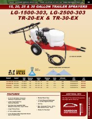
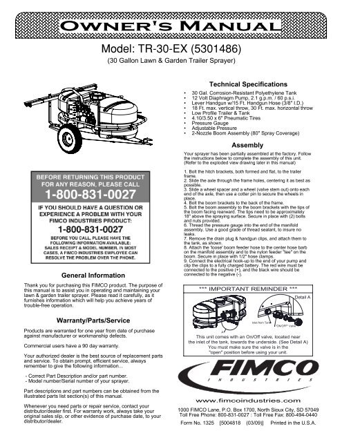
<strong>Owner's</strong> <strong>Manual</strong><br />
<br />
(30 Gallon Lawn & Garden Trailer Sprayer)<br />
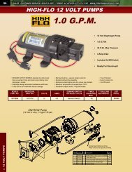
Technical Specifications<br />
• 30 Gal. Corrosion-Resistant Polyethylene Tank<br />
• 12 Volt Diaphragm Pump, 2.1 g.p.m. / 60 p.s.i.<br />
• Lever Handgun w/15 Ft. Handgun Hose (3/8" I.D.)<br />
• 18 Ft. max. vertical throw, 30 Ft. max. horizontal throw<br />
• Low Profile Trailer & Tank<br />
• 4.10/3.50 x 6" Pneumatic Tires<br />
• Pressure Gauge<br />
• Adjustable Pressure<br />
• 2-Nozzle Boom Assembly (80" Spray Coverage)<br />
Assembly<br />
Your sprayer has been partially assembled at the factory. Follow<br />
the instructions below to complete the assembly of this unit.<br />
(Refer to the exploded view drawing later in this manual)<br />
General Information<br />
Thank you for purchasing this <strong>FIMCO</strong> product. The purpose of<br />
this manual is to assist you in operating and maintaining your<br />
lawn & garden trailer sprayer. Please read it carefully, as it<br />
furnishes information which will help you achieve years of<br />
trouble-free operation.<br />
Warranty/Parts/Service<br />
Products are warranted for one year from date of purchase<br />
against manufacturer or workmanship defects.<br />
Commercial users have a 90 day warranty.<br />
Your authorized dealer is the best source of replacement parts<br />
and service. To obtain prompt, efficient service, always<br />
remember to give the following information...<br />
1. Bolt the hitch brackets, both formed and flat, to the trailer<br />
frame.<br />
2. Slide the axle through the frame holes, centering it as best as<br />
possible.<br />
3. Slide a wheel spacer and a wheel (valve stem out) onto each<br />
end of the axle, then use a cotter pin to secure the wheels in<br />
place.<br />
4. Bolt the boom brackets to the back of the frame.<br />
5. Bolt the boom assembly to the boom brackets with the tips of<br />
the boom facing rearward. The tips need to be approximately<br />
18" above the spraying surface. Secure in place with (2) bolts<br />
and nuts provided.<br />
6. Thread the pressure gauge into the end of the manifold<br />
assembly. Use a good grade of thread sealant, to insure no<br />
leaks.<br />
7. Remove the drain plug & handgun clips, and attach them to<br />
the tank, as shown.<br />
8. Attach the 'loose' boom feeder hose to the center hose barb<br />
on the manifold assembly and to the nylon feeder "tee" on the<br />
boom. Secure in place with 1/2" hose clamps.<br />
9. Connect the electrical hook-up to the end of your pump and<br />
clip the clips to a fully charged battery. The red wire must be<br />
connected to the positive (+), and the black wire should be<br />
connected to the negative (-).<br />
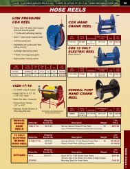
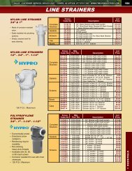
*** IMPORTANT REMINDER ***<br />
A<br />
Inlet from Tank<br />
"ON/OFF" Valve<br />
Detail A<br />
This unit comes with an On/Off valve, located near<br />
the inlet of the tank, towards the underside. (See Detail A)<br />
You must make sure the valve is in the<br />
"open" position before using your unit.<br />
- Correct Part Description and/or part number.<br />
- Model number/Serial number of your sprayer.<br />
Part descriptions and part numbers can be obtained from the<br />
illustrated parts list section(s) of this manual.<br />
Whenever you need parts or repair service, contact your<br />
distributor/dealer first. For warranty work, always take your<br />
original sales slip, or other evidence of purchase date, to your<br />
distributor/dealer.<br />
www.fimcoindustries.com<br />
1000 <strong>FIMCO</strong> Lane, P.O. Box 1700, North Sioux City, SD 57049<br />
Toll Free Phone: 800-831-0027 : Toll Free Fax: 800-494-0440<br />
Form No. 1325 [5004818 (03/09)] Printed in the U.S.A.
Testing the Sprayer<br />
NOTE:<br />
It is VERY important for you to test your sprayer with<br />
plain water before actual spraying is attempted. This will<br />
enable you to check the sprayer for leaks, without the<br />
possibility of losing any expensive chemicals.<br />
Add water to the tank & drive to the starting place for<br />
spraying. When you are ready to spray, turn the boom valve<br />
to the "on" position. This will start solution spraying from the<br />
tips of the boom. The pressure will decrease slightly when the<br />
boom is spraying. Adjust the pressure by turning the<br />
"ON/OFF" valve lever on the bypass line valve.<br />
Read the operating instructions and Initially begin spraying by<br />
closing the 'bypass' valve (this is the center ON/OFF valve<br />
located at the center port of your manifold assembly) and<br />
opening the boom line valve (this is the 'other' valve on the<br />
manifold). This will enable the air in the line to be eliminated<br />
(purged) through all the tips, while building pressure. When<br />
everything tests all right (no leaks, & good pressure), add the<br />
desired chemicals to the mixture and water combination and<br />
start your spraying operation. Adjust the pressure and spray<br />
as you did in the testing procedure.<br />
Conditions of weather and terrain must be considered when<br />
setting the sprayer. Do not spray on windy days. Protective<br />
clothing must be worn in some cases.<br />
Be sure to read the chemical label(s) correctly!<br />
Calibration<br />
Chemical labels may show application rates in gallons per<br />
acre, gallons per 1000 square feet, or gallons per 100<br />
square feet. You will note that the tip chart shows all 3 of<br />
these rating systems.<br />
Once you know how much you are going to spray, then<br />
determine (from the tip chart) the spraying pressure (PSI),<br />
and the spraying speed (MPH).<br />
Determining the proper speed of the pulling vehicle can be<br />
done by marking off 100, 200, & 300 feet. The speed chart<br />
indicates the number of seconds it takes to travel the<br />
distances. Set the throttle and with a running start, travel the<br />
distances. Adjust the throttle until you travel the distances in<br />
the number of seconds indicated by the speed chart. Once<br />
you have reached the throttle setting needed, mark the<br />
throttle location so you can stop and go again, returning to<br />
the same speed.<br />
Add water and proper amount of chemical to the tank and<br />
drive to the starting place for spraying.<br />
Operation<br />
Your sprayer is equipped with (2) ON/OFF switches. One is on<br />
the wire assembly that you hook up to your battery, the other is<br />
on the pump itself, on the opposite end of the pressure switch.<br />
The "-" is the "ON" position and the "o" is the "OFF" position for<br />
the switches. Make sure both switches are depressed in the "-"<br />
position for operation.<br />
In addition to the ON/OFF switch, the pump is equipped with an<br />
electronic pressure switch that is factory pre-set for it to shut off<br />
at 60 p.s.i.. This switch assembly is the 'square box' on the head<br />
portion of the pump.<br />
Always fill the tank with a desired amount of water first, and then<br />
add the chemical slowly, mixing as you pour the chemical into<br />
the tank. You may use the handgun to spray into the solution in<br />
order to mix the chemical and water.<br />
Initially begin spraying by opening the handgun. This will enable<br />
the air in the line to be purged through the handgun tip, while<br />
building pressure.<br />
The pumping system draws solution from the tank, through the<br />
strainer/filter, and to the pump. The pump forces the solution<br />
under pressure to the handgun and/or boom nozzles.<br />
• Open the handgun by squeezing the handle lever.<br />
• Rotating the adjustable nozzle tip on the handgun will<br />
change the tip pattern from a straight stream to a cone<br />
pattern (finer mist).<br />
NOTE: Make sure the tires are inflated to 30 psi prior to use.<br />
Tip Spray<br />
No. Height Pressure Capacity<br />
(psi) (GPM)<br />
3 18"<br />
10<br />
20<br />
30<br />
40<br />
.30<br />
.42<br />
.52<br />
.60<br />
Tip Chart<br />
Gallons Per Acre - Based on Water<br />
1<br />
MPH MPH 2<br />
MPH 3<br />
MPH 4<br />
MPH 5<br />
MPH<br />
7.5<br />
44<br />
63<br />
76<br />
90<br />
22<br />
31.5<br />
38<br />
45<br />
14.9<br />
20.9<br />
26<br />
30<br />
11.1<br />
15.7<br />
19.3<br />
22<br />
8.9<br />
12.6<br />
15.4<br />
17.8<br />
5.9<br />
8.4<br />
10.3<br />
11.8<br />
Tip Spray<br />
No. Height Pressure Capacity<br />
(psi) (GPM) 1<br />
MPH MPH 2<br />
MPH 3<br />
MPH 4<br />
MPH 5<br />
MPH<br />
7.5<br />
3 18"<br />
10<br />
20<br />
30<br />
40<br />
.30<br />
.42<br />
.52<br />
.60<br />
10<br />
MPH<br />
4.5<br />
6.3<br />
7.7<br />
8.9<br />
Gallons Per 1000 Sq. Ft. - Based on Water<br />
1.01<br />
1.4<br />
1.74<br />
2.06<br />
.50<br />
.72<br />
.87<br />
1.00<br />
.34<br />
.48<br />
.596<br />
.688<br />
.254<br />
.36<br />
.44<br />
.50<br />
.204<br />
.29<br />
.35<br />
.408<br />
.135<br />
.19<br />
.236<br />
.27<br />
10<br />
MPH<br />
.103<br />
.14<br />
.176<br />
.20<br />
Gallons Per 100 Sq. Ft. - Based on Water<br />
Tip Spray<br />
No. Height Pressure Capacity<br />
(psi) (GPM) 1<br />
MPH MPH 2<br />
MPH 3<br />
MPH 4<br />
MPH 5<br />
MPH<br />
7.5<br />
10<br />
MPH<br />
Speed Chart<br />
Time Required in seconds to travel a distance of:<br />
Speed in M.P.H.<br />
(Miles per Hour)<br />
100 Ft. 200 Ft. 300 Ft.<br />
1.0 68 sec. 136 sec. 205 sec.<br />
2.0 34 68 102<br />
3.0 23 45 68<br />
4.0 17 34 51<br />
5.0 14 27 41<br />
6.0 11 23 34<br />
7.0 9.7 19 29<br />
8.0 8.5 17 26<br />
9.0 7.6 15 23<br />
10.0 6.8 14 20<br />
3 18"<br />
10<br />
20<br />
30<br />
40<br />
.30<br />
.42<br />
.52<br />
.60<br />
.10<br />
.14<br />
.174<br />
.206<br />
.05<br />
.072<br />
.087<br />
.10<br />
.034<br />
.048<br />
.059<br />
.068<br />
.025<br />
.036<br />
.044<br />
.05<br />
.02<br />
.029<br />
.035<br />
.04<br />
.013<br />
.019<br />
.023<br />
.027<br />
.01<br />
.014<br />
.017<br />
.02<br />
Page 2
After Spraying<br />
After use, fill the sprayer tank part way with water. Start the<br />
sprayer, and allow the clear water to be pumped through the<br />
plumbing system and out through the spray nozzles.<br />
Refill the tank about half full with plain water and use a<br />
chemical neutralizer, such as 'Nutra-Sol', or equivalent, and<br />
repeat cleaning instructions above. A mix of water and some<br />
detergent, such as 'Dawn' dish soap would be a sufficient<br />
alternative.<br />
Flush the entire sprayer with the neutralizing/cleaning agent,<br />
then flush out one more time with plain water. Follow the<br />
chemical manufacturer's disposal instructions of all wash or<br />
rinsing water.<br />
For the boom, (if applicable) remove the tips and screens<br />
from the nozzle assemblies. Wash these items out<br />
thoroughly. Blow the orifice clean and dry. If the orifice<br />
remains clogged, clean it with a fine bristle (NOT WIRE)<br />
brush, or with a toothpick. Do not damage the orifice. Water<br />
rinse and dry the tips before storing.<br />
WARNING: Some chemicals will damage the pump<br />
valves if allowed to soak untreated for a length of time!<br />
ALWAYS flush the pump as instructed after each use.<br />
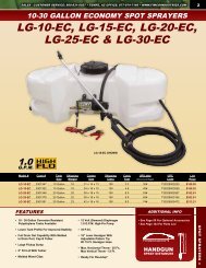
Troubleshooting a 2.1 g.p.m. Pump:<br />
Pump will NOT run:<br />
- Check inline fuse on the wires on the pump. If blown, replace<br />
with new fuse. (7.5 Amp mini-blade fuse #5157205)<br />
- Make sure BOTH on/off switches are in the 'on' position (-).<br />
- Make sure you 12 volt source (battery) is fully charged.<br />
- Insure a tight connection at the battery clips.<br />
If none of the above will work, try pulling wire terminal "A" off<br />
of the spade terminal of the pressure switch, and cross it over<br />
and touch terminal "B". (You will need to remove the pressure<br />
switch cap before doing this) If your pump runs when you do<br />
this, you know you will need to replace your pressure switch.<br />
Another thing you can try is to take apart the switch box on<br />
the lead wire assembly (#5274443) with the (2) phillips head<br />
screws, and 'hot-wire' it together. Take the (2) wires that are<br />
screwed to the rocker switch, off of the switch and twist them<br />
together. This will insure you are getting the full 12 volts to the<br />
pump. If your pump runs after doing this, you will know that<br />
your lead wire assembly needs to be replaced.<br />
Winter Storage<br />
Drain all water out of your sprayer, paying special attention<br />
to the pump, handgun, and valve(s). These items are<br />
especially prone to damage from chemicals and freezing<br />
weather.<br />
The sprayer should be winterized before storage by<br />
pumping a solution of RV antifreeze through the entire<br />
plumbing system. This antifreeze solution should remain in<br />
the plumbing system during the winter months. When<br />
spring time comes and you are preparing your sprayer for<br />
the spray season, rinse the entire plumbing system out,<br />
clearing the lines of the antifreeze solution. Proper care<br />
and maintenance will prolong the life of your sprayer.<br />
Pump runs, but does not prime:<br />
- Check line strainer (screen) at the inlet location, at the<br />
tank. You will need to unscrew the knurled nut to access<br />
this screen. (see exploded view later in this manual) The<br />
ON/OFF valve should be closed while performing this, to<br />
insure you do not lose any solution. Periodically take the<br />
screen at this location out and clean it.<br />
- Make sure the bypass line valve is closed, to allow the<br />
pressure to build up in your system.<br />
- Unscrew the head portion of your pump and remove the<br />
check valve assembly from inside. You need to make sure<br />
the O-Ring comes out with this piece as well. (See the<br />
exploded view to help identify these components) These<br />
pieces can be cleaned which, in most cases, will help<br />
restore some, if not most, of your prime. Soak this check<br />
valve in a solution of hot, soapy water. "Dawn" brand<br />
dishsoap works well for this. A little bit of 'scrubbing' with<br />
perhaps an old toothbrush may be required to actually<br />
break up any build-up that may be on the check valve.<br />
Rinse off the pieces and replace them back into your<br />
pump. Reassemble the pump. Hook it back up and test.<br />
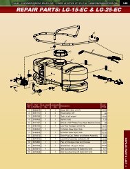
#5275703 Pump<br />
(12 Volt, 8 Amp, 2.1 gpm, 60 psi)<br />
1<br />
2<br />
"A"<br />
5.1<br />
*<br />
3.2<br />
3.1<br />
3<br />
3.3<br />
"B"<br />
5.2<br />
Fittings with an asterisk (*) by<br />
them, come together in a bag,<br />
part #7771824<br />
(1) 5168832 - 1/2" MNPT<br />
(1) 5168833 - 1/2" Hose Barb<br />
(1) 5168836 - 3/8" Hose Barb<br />
4<br />
*<br />
*<br />
Item<br />
No<br />
Part<br />
Number<br />
Qty Description<br />
List<br />
Price<br />
1 5157205 1 7.5 Amp Mini Fuse 1.00<br />
2 5168820 1 Check Valve Kit (w/O-Ring) 19.95<br />
3 5168837 1 Upper Housing Assembly 39.95<br />
3.1 5168839 1 Plunger Kit 12.99<br />
3.2 5157202 1 Pressure Switch Assembly 23.95<br />
3.3 20408-000 1 Pkg. (2) Clips (Port Fitting) 3.41<br />
4 5168838 1 Diaphragm/Cam/Bearing Kit 18.99<br />
5.1 5157207 1 Rocker Switch 6.99<br />
5.2 5095202 4 Pump Foot (1.0 & 2.1 g.p.m.) 1.29<br />
Page 3
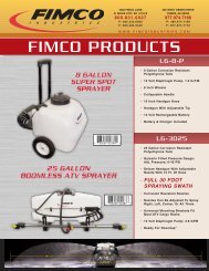
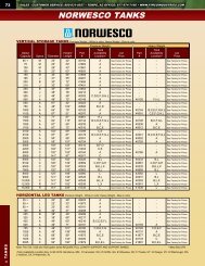
Exploded View/Parts List: TR-30-EX (5301486)<br />
36.4<br />
36.9<br />
36.3<br />
2<br />
36.1<br />
2<br />
36.4<br />
36.5<br />
36.9<br />
36.3<br />
36.6<br />
8<br />
36.7<br />
36.8<br />
36.2<br />
5<br />
14<br />
24<br />
16<br />
15<br />
14<br />
36.2 36.8<br />
36.6<br />
36.7<br />
19<br />
8<br />
8<br />
19<br />
8<br />
18<br />
31<br />
30<br />
28<br />
33<br />
4<br />
29<br />
34.9 34.4<br />
34.3<br />
34.8<br />
34.2<br />
34.7<br />
34.6<br />
13<br />
34.7<br />
1<br />
20<br />
3<br />
34.5<br />
34.3<br />
34.4<br />
34.1<br />
27<br />
6<br />
25<br />
26<br />
27<br />
23 35<br />
22<br />
7<br />
37.6<br />
2<br />
37.2<br />
37.7<br />
37.7<br />
22<br />
37.5<br />
21<br />
37.3<br />
37.4<br />
37.1<br />
17<br />
10<br />
26<br />
9<br />
32<br />
6<br />
11<br />
12<br />
2<br />
Item<br />
No<br />
Part<br />
Number<br />
Qty Description<br />
List<br />
Price<br />
1 5006209 1 Poly Knurled Swivel Nut, 3/4" FGHT .57<br />
2 5006307 8 5/16"-18 Hex Whiz (Flange) Locknut .25<br />
3 5016066 1 Garden Hose Washer .20<br />
4 5020009 1 Hose, 1/2"-1 Brd. x 26" 2.66<br />
5 5020215 1 Hose, 3/8"-1 Brd. x 15 Ft. 8.50<br />
6 5021102 2<br />
4.10/3.50-6 Wheel (White) w/2 1/4" Offset & 5/8"<br />
BB<br />
29.95<br />
7 5024102 1 Axle (5/8" Dia.) 8.11<br />
8 5034038 6 H.H.C.S., 5/16"-18 x 3/4" .55<br />
9 5034042 2 H.H.C.S., 5/16"-18 x 1" .25<br />
10 5034531 4 5/16"-18 x 5/8" Flange Lock Screw .44<br />
11 5038517 1 Hitch Bracket (Formed) 4.85<br />
12 5038518 1 Hitch Bracket (Flat) 2.30<br />
13 5051022 2 Hose Clamp, 1/2" .62<br />
14 5051114 2 Hose Clamp, 3/8" .63<br />
15 5051122 1 5/8" Black Nylon Loom Cable Clamp .25<br />
16 5058188 1 Tank Lid w/Lanyard 10.50<br />
17 5070063 1<br />
Trailer Frame (RED: 25 & 30 Gal. "New" Style<br />
Tanks)<br />
45.15<br />
18 5075018 1 Grommet 1.00<br />
19 5095198 2 Boom Bracket (Light Duty) 2.00<br />
20 5100359 1<br />
Poly Bypass "J" Hose (3.8 Pumps & 2.1 [25]<br />
Gallon)<br />
1.95<br />
21 5100452 1 Siphon Tube 1.20<br />
22 5101077 2 Cotter Pin, 1/8" x 1" .25<br />
23 5117167 3 #10-24 x 5/8" Phillips Truss Head Machine Screw .25<br />
24 5117234 1 #10-24 x 1/2" Phillips Truss Head Machine Screw .25<br />
25 5117313 1 #10-24 x 2 1/2" Truss Head Machine Screw .25<br />
26 5127189 2 Bushing (25/30 Gallon Trailer) .50<br />
27 5127191 1 Manifold Spacer (2.1gpm) .40<br />
28 5163100 1 Low-Flow Handgun w/X-26 Tip 9.95<br />
29 5167007 1 Gauge, 0-100 p.s.i. 6.25<br />
Page 4<br />
(List Prices are Subject to Change)<br />
Item<br />
No<br />
Part<br />
Number<br />
Qty Description<br />
List<br />
Price<br />
30 5169244 1 30 Gallon (New Style) Tank 65.00<br />
31 5274373 1 Drain Plug Cap, Tether, and Washer Assembly 2.95<br />
32 5274443 1 Lead Wire Assembly (w/Switch), 96" 9.99<br />
33 5274880 1 Pkg. (2) Handgun Clips & (2) Screws 2.85<br />
34 5275516 1 Manifold Assembly 18.00<br />
34.1 5010430 1 Port Kit Elbow, 1/2" FNPT 2.79<br />
34.2 5143405 1 Manifold w/Mounting Tab 6.99<br />
34.3 5143188 2 Nylon Shut-Off Valve 3.10<br />
34.4 5016066 2 Garden Hose Washer .20<br />
34.5 5149034 1 Poly Swivel, 3/8" Hose Barb .50<br />
34.6 5149035 1 Poly Swivel, 1/2" Hose Barb .50<br />
34.7 5006209 2 Poly Knurled Swivel Nut, 3/4" FGHT .57<br />
34.8 5010236 1 Poly Elbow, 1/2" FNPT x 1/2" FNPT 2.07<br />
34.9 5041073 1 Poly Reducing Bushing, 1/2" MNPT x 1/4" FNPT 1.24<br />
35 5275703 1 Gold Series 2.1 g.p.m. Pump 112.00<br />
36 5275726 1 2-Nozzle Boom Assembly 26.01<br />
36.1 5022411 1 Boom Mount Angle 5.85<br />
36.2 5056023 2 Nylon Elbow Assembly, 11/16" U.N.F. x 1/2" HB 1.35<br />
36.3 5116019 2 50 Mesh Nozzle Strainer, Red 1.05<br />
36.4 5046052 2 Nylon Nozzle Cap, 11/16" U.N.F. Thread .38<br />
36.5 5086003 1 Nylon Hose Tee, 1/2" HB .88<br />
36.6 5133094 2 Nylon Cable Tie .25<br />
36.7 5020416 2 Hose, 1/2"-1 Brd. x 19 3/8" 2.17<br />
36.8 5051022 4 Hose Clamp, 1/2" .62<br />
36.9 5018327 2 FloodJet Tip 2.41<br />
37 5275877 1 Intake Sub-Assembly 7.49<br />
37.1 5143188 1 Nylon Shut-Off Valve 3.10<br />
37.2 5168833 1 Port Kit Fitting, 1/2" Hose Barb 2.24<br />
37.3 5116242 1 Strainer, 1" Filter Washer .31<br />
37.4 5149035 1 Poly Swivel, 1/2" Hose Barb .50<br />
37.5 5006209 1 Poly Knurled Swivel Nut, 3/4" FGHT .57<br />
37.6 5020497 1 1/2" Polyspring Hose x 6" 1.69<br />
37.7 5051022 2 Hose Clamp, 1/2" .62