

PROGRESS REPORT - ENEA - Fusione
PROGRESS REPORT - ENEA - Fusione
PROGRESS REPORT - ENEA - Fusione

Create successful ePaper yourself
Turn your PDF publications into a flip-book with our unique Google optimized e-Paper software.
A2 Preliminary Design of FT3<br />
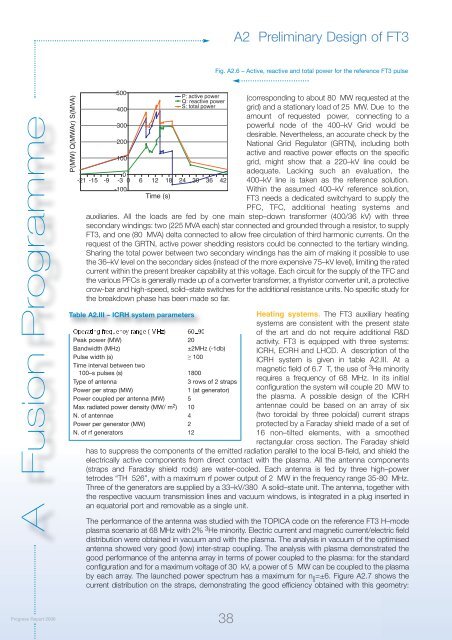
Fig. A2.6 – Active, reactive and total power for the reference FT3 pulse<br />
A Fusion Programme<br />
P(MW) Q(MWAr) S(MVA)<br />
500<br />
400<br />
300<br />
200<br />
100<br />
P: active power<br />
Q: reactive power<br />
S: total power<br />
0<br />
-21 -15 -9 -3 0 6 12 18 24 30 36 42<br />
-100<br />
Time (s)<br />
(corresponding to about 80 MW requested at the<br />
grid) and a stationary load of 25 MW. Due to the<br />
amount of requested power, connecting to a<br />
powerful node of the 400–kV Grid would be<br />
desirable. Nevertheless, an accurate check by the<br />
National Grid Regulator (GRTN), including both<br />
active and reactive power effects on the specific<br />
grid, might show that a 220–kV line could be<br />
adequate. Lacking such an evaluation, the<br />
400–kV line is taken as the reference solution.<br />
Within the assumed 400–kV reference solution,<br />
FT3 needs a dedicated switchyard to supply the<br />
PFC, TFC, additional heating systems and<br />
auxiliaries. All the loads are fed by one main step–down transformer (400/36 kV) with three<br />
secondary windings: two (225 MVA each) star connected and grounded through a resistor, to supply<br />
FT3, and one (80 MVA) delta connected to allow free circulation of third harmonic currents. On the<br />
request of the GRTN, active power shedding resistors could be connected to the tertiary winding.<br />
Sharing the total power between two secondary windings has the aim of making it possible to use<br />
the 36–kV level on the secondary sides (instead of the more expensive 75–kV level), limiting the rated<br />
current within the present breaker capability at this voltage. Each circuit for the supply of the TFC and<br />
the various PFCs is generally made up of a converter transformer, a thyristor converter unit, a protective<br />
crow-bar and high-speed, solid–state switches for the additional resistance units. No specific study for<br />
the breakdown phase has been made so far.<br />
Table A2.III – ICRH system parameters<br />
Operating frequency range ( MHz) 60±90<br />
Peak power (MW) 20<br />
Bandwidth (MHz)<br />
±2MHz (-1db)<br />
Pulse width (s) ≥ 100<br />
Time interval between two<br />
100–s pulses (s) 1800<br />
Type of antenna<br />
3 rows of 2 straps<br />
Power per strap (MW)<br />
1 (at generator)<br />
Power coupled per antenna (MW) 5<br />
Max radiated power density (MW/ m 2 ) 10<br />
N. of antennae 4<br />
Power per generator (MW) 2<br />
N. of rf generators 12<br />
Heating systems. The FT3 auxiliary heating<br />
systems are consistent with the present state<br />
of the art and do not require additional R&D<br />
activity. FT3 is equipped with three systems:<br />
ICRH, ECRH and LHCD. A description of the<br />
ICRH system is given in table A2.III. At a<br />
magnetic field of 6.7 T, the use of 3 He minority<br />
requires a frequency of 68 MHz. In its initial<br />
configuration the system will couple 20 MW to<br />
the plasma. A possible design of the ICRH<br />
antennae could be based on an array of six<br />
(two toroidal by three poloidal) current straps<br />
protected by a Faraday shield made of a set of<br />
16 non–tilted elements, with a smoothed<br />
rectangular cross section. The Faraday shield<br />
has to suppress the components of the emitted radiation parallel to the local B-field, and shield the<br />
electrically active components from direct contact with the plasma. All the antenna components<br />
(straps and Faraday shield rods) are water-cooled. Each antenna is fed by three high–power<br />
tetrodes “TH 526”, with a maximum rf power output of 2 MW in the frequency range 35-80 MHz.<br />
Three of the generators are supplied by a 33–kV/380 A solid–state unit. The antenna, together with<br />
the respective vacuum transmission lines and vacuum windows, is integrated in a plug inserted in<br />
an equatorial port and removable as a single unit.<br />
The performance of the antenna was studied with the TOPICA code on the reference FT3 H–mode<br />
plasma scenario at 68 MHz with 2% 3 He minority. Electric current and magnetic current/electric field<br />
distribution were obtained in vacuum and with the plasma. The analysis in vacuum of the optimised<br />
antenna showed very good (low) inter-strap coupling. The analysis with plasma demonstrated the<br />
good performance of the antenna array in terms of power coupled to the plasma: for the standard<br />
configuration and for a maximum voltage of 30 kV, a power of 5 MW can be coupled to the plasma<br />
by each array. The launched power spectrum has a maximum for n || =±6. Figure A2.7 shows the<br />
current distribution on the straps, demonstrating the good efficiency obtained with this geometry:<br />
Progress Report 2006<br />
38


