1 EDK Tutorial 4 Simulating with BFM and Modelsim SE - Cosmiac
1 EDK Tutorial 4 Simulating with BFM and Modelsim SE - Cosmiac
1 EDK Tutorial 4 Simulating with BFM and Modelsim SE - Cosmiac

You also want an ePaper? Increase the reach of your titles
YUMPU automatically turns print PDFs into web optimized ePapers that Google loves.
<strong>EDK</strong> <strong>Tutorial</strong> 4<br />
<strong>Simulating</strong> <strong>with</strong> <strong>BFM</strong> <strong>and</strong> <strong>Modelsim</strong> <strong>SE</strong><br />
-Introduction<br />
<strong>Modelsim</strong> <strong>SE</strong> is a st<strong>and</strong>ard for simulating large scale projects. The ability to simulate the<br />
entire <strong>EDK</strong> system is a major benefit for debugging components of the project as well as<br />
the entire system.<br />
The software provided by UNM is for academic use only. It is not intended for<br />
commercial work <strong>and</strong> should not be used for such.<br />
-Objective<br />
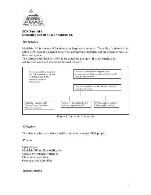
Figure 1. Entire list of tutorials<br />
The objective is to use <strong>Modelsim</strong><strong>SE</strong> to simulate a simple <strong>EDK</strong> project.<br />
-Process<br />
Open project<br />
<strong>Modelsim</strong><strong>SE</strong>.ini file modification<br />
Update environment variables<br />
Clean simulation files<br />
Generate simulation files<br />
-Implementation<br />
1
Figure 2. Modifying Hello World C code<br />
Open the previously created project from <strong>Tutorial</strong> 1. Modify the hello world file as<br />
shown above. This will print a single “U” to the UART. The significance of this is that<br />
the character “U” is 55 in hex. This will allow visualization of a nice waveform.<br />
Figure 3. Change UART<br />
2
Change the rate of the UART. This will allow the simulation not to have to run as long.<br />
Figure 4. Generate test bench<br />
Generate the test bench template for simulation.<br />
Figure 5. Simulate <strong>with</strong> <strong>SE</strong><br />
3
Use the <strong>Modelsim</strong> <strong>SE</strong> simulator that has been loaded.<br />
Figure 6. HDLs Supported<br />
Select appropriate HDLs to support or just leave as default.<br />
Point to the correct library locations.<br />
Figure 7. Library Locations<br />
4
Point to the correct library locations.<br />
Compile all libraries.<br />
Figure 8. Library Locations<br />
Figure 9. Recompile<br />
5
Clean all older simulation files.<br />
Figure 10. Clean Simulation<br />
Figure 11. Generate Simulation Files<br />
Regenerate the Simulation HDL files for running the new simulation.<br />
6
Launch the <strong>Modelsim</strong> Simulator.<br />
Figure 12. Launch Simulator<br />
Figure 13. Compile the designs<br />
Compile the design <strong>and</strong> simulation files into <strong>Modelsim</strong>.<br />
7
Load the design into the Simulator.<br />
Figure 14. Load the design<br />
Figure 15. Set up waveform window<br />
Set up the waveform window. When this is done, the various signals associated <strong>with</strong> the<br />
project should be visiable.<br />
8
Figure 16. Run Simulation<br />
Run the simulation. For this tutorial, 2ms was chosen as it was a sufficient amount of<br />
time to obtain output data from the UART. This is a user choice.<br />
Figure 17. Undock waveform window<br />
By undocking the waveform window, it is easier to visualize all the signals.<br />
9
Figure 18. Waveforms<br />
There are many signals that are displayed in the simulation. The user should spend time<br />
going through some of them to include the general purpose registers.<br />
Figure 19. “U” on Transmit<br />
By exp<strong>and</strong>ing the UART transmit it is possible to see the 01010101 that represents the<br />
“U” coming out of the UART.<br />
10
Figure 20. Launch <strong>EDK</strong> Shell<br />
Another useful tool is the capability to visualize the Assembly code. To do this it will be<br />
necessary to disassemble the .elf file. Launch the <strong>EDK</strong> Shell.<br />
Figure 21. Transit to .elf file<br />
Travel into your project director <strong>and</strong> go to the executable.elf file.<br />
Figure 22. Disassembly of .elf file<br />
11
Disassemble the .elf file into a text tile. In this tutorial, the dump.dis file name was<br />
chosen.<br />
Using WordPad, open the .dis file.<br />
Figure 23. Open .dis file<br />
Figure 24. Dump file<br />
If the user searches for the “U” then they will see the applicable assembly code.<br />
12
Attachment 1<br />
This is an excerpt from a Xilinx Application Note for modifying the modelsim.ini file<br />
MTI ModelSim <strong>SE</strong> <strong>and</strong> ModelSim PE (5.7 or later) - Windows 2000/XP<br />
Simulator Setup<br />
NOTE: When using ModelSim PE (5.7 or later), the SWIFT interface must be enabled.<br />
Please contact the vendor to enable this option.<br />
Although ModelSim <strong>SE</strong> <strong>and</strong> ModelSim PE (5.7 or later) support the SWIFT Interface,<br />
you must make certain modifications to the default ModelSim setup to enable this<br />
feature.<br />
You must make the following changes to the "modelsim.ini" file located in the<br />
"%MODEL_TECH%" directory:<br />
1. After the lines:<br />
; Simulator resolution<br />
; Set to fs, ps, ns, us, ms, or sec <strong>with</strong> optional prefix of 1, 10, or 100.<br />
edit the statement that follows, from "Resolution = ns" to "Resolution = ps."<br />
2. After the lines:<br />
; Specify whether paths in simulator comm<strong>and</strong>s should be described<br />
; in VHDL or Verilog format. For VHDL, PathSeparator = /<br />
; for Verilog, PathSeparator = .<br />
comment the following statement by adding a semicolon (;) at the beginning of the line:<br />
PathSeparator = /<br />
3. After the line:<br />
; List of dynamically loaded objects for Verilog PLI applications<br />
add the following statement:<br />
Veriuser=$MODEL_TECH/libswiftpli.dll<br />
4. After the line:<br />
; Logic Modeling's SmartModel SWIFT software (Windows NT)<br />
add the following statements:<br />
libsm = $MODEL_TECH/libsm.dll<br />
libswift=$LMC_HOME/lib/pcnt.lib/libswift.dll<br />
NOTE: It is important that you change the order in which the comm<strong>and</strong>s appear in the<br />
"modelsim.ini" file. The simulation might not work if you do not follow the order<br />
recommended above.<br />
13
Attachment 2<br />
Compiling the <strong>Modelsim</strong> Libraries <strong>and</strong><br />
______________________________________________<br />
I would first install the <strong>BFM</strong> package then compile libraries.<br />
To compile libraries it should look like the following setup which I think is default. If it<br />
isn’t the default, then it is a good idea to place the compiled libraries into a common<br />
location such as “sim.”<br />
Then you would use the same C:\simlib\<strong>EDK</strong>9.2_mti_se_nt path for the <strong>EDK</strong>_Lib.<br />
Then make sure the smartmodel paths are setup correctly for the environmental variables<br />
<strong>and</strong> the modelsim.ini. Which the installed path for the Smartmodels is at<br />
C:\simlib\<strong>EDK</strong>9.2_mti_se_nt\smartmodel\nt\installed_nt.<br />
Smartmodels are used for the PPC405 model.<br />
The I<strong>SE</strong>_Lib is used for base components like FIFOs etc.<br />
The <strong>EDK</strong>_Lib is used for the cores inside <strong>EDK</strong>.<br />
You need to add the correct environmental variables like:<br />
LMC_HOME C:\simlib\<strong>EDK</strong>9.2_mti_se_nt\smartmodel\nt\installed_nt<br />
Add to the PATH %LMC_HOME%\bin;%LMC_HOME%\lib\pcnt.lib;<br />
14