

Solar Nexus Power Center Installation Manual
Solar Nexus Power Center Installation Manual
Solar Nexus Power Center Installation Manual

Create successful ePaper yourself
Turn your PDF publications into a flip-book with our unique Google optimized e-Paper software.
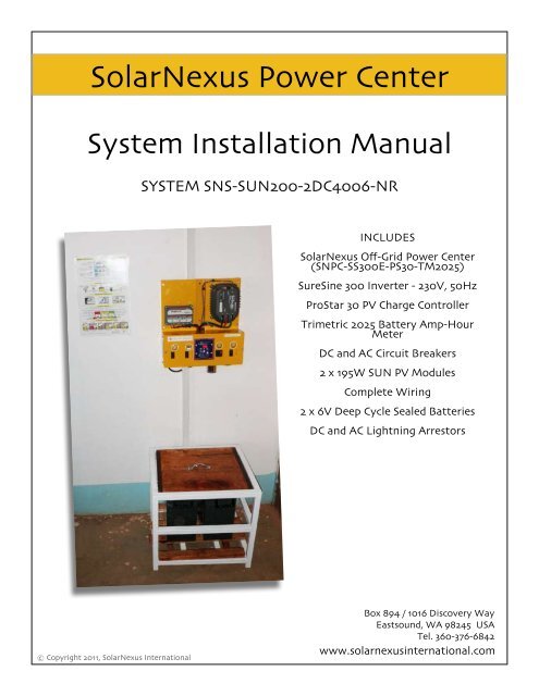
<strong>Solar</strong><strong>Nexus</strong> <strong>Power</strong> <strong>Center</strong><br />
System <strong>Installation</strong> <strong>Manual</strong><br />
SYSTEM SNS-SUN200-2DC4006-NR<br />
INCLUDES<br />
<strong>Solar</strong><strong>Nexus</strong> Off-Grid <strong>Power</strong> <strong>Center</strong><br />
(SNPC-SS300E-PS30-TM2025)<br />
SureSine 300 Inverter - 230V, 50Hz<br />
ProStar 30 PV Charge Controller<br />
Trimetric 2025 Battery Amp-Hour<br />
Meter<br />
DC and AC Circuit Breakers<br />
2 x 195W SUN PV Modules<br />
Complete Wiring<br />
2 x 6V Deep Cycle Sealed Batteries<br />
DC and AC Lightning Arrestors<br />
© Copyright 2011, <strong>Solar</strong><strong>Nexus</strong> International<br />
Box 894 / 1016 Discovery Way<br />
Eastsound, WA 98245 USA<br />
Tel. 360-376-6842<br />
www.solarnexusinternational.com
WARNING: No spare parts included. Don’t lose anything!<br />
System Parts List<br />
Major Components<br />
1.<br />
2.<br />
3.<br />
4.<br />
5.<br />
2 - SUN Photovoltaic Module 195W - 2<br />
1 - <strong>Solar</strong><strong>Nexus</strong> <strong>Power</strong> <strong>Center</strong> (SNPC-SS300E-PS30-<br />
TM2025)<br />
2 - Sealed AGM Batteries - 6V 400 Amp-Hours<br />
Balance of Systems Box - 1<br />
1 - <strong>Solar</strong> Panel Combiner Box Bracket (Aluminum)<br />
6.<br />
7.<br />
8.<br />
9.<br />
#2 USE-2 PV <strong>Solar</strong> Array Wire<br />
#4 USE-2 PV <strong>Solar</strong> Array Wire<br />
#6 Bare Copper Ground Wire for <strong>Solar</strong> Systems<br />
#10 XHHW Stranded Green 500R Wire<br />
Balance of Systems Box<br />
1. 1 - <strong>Solar</strong> <strong>Nexus</strong> PV Combiner box (SNPVC)<br />
2. 1 - DC Lightning Arrestor (LA302)<br />
3. 1 - AC Lightning Arrestor (LA302R)<br />
4. 1 - Battery Jumper Cable Assembly<br />
5. 1 - <strong>Solar</strong> Array Wire Assembly (MC extension 6<br />
cable) - 1/2m<br />
6. 1 - <strong>Solar</strong> Array Wire Assembly (MC extension<br />
cable) - 2m<br />
7. 10 - UV-Resistant Cable Ties - 14.5” - 120#<br />
9<br />
8. Product Literature<br />
9. 1 - BOS Hardware Bag (see contents below)<br />
7<br />
8<br />
1<br />
5<br />
4<br />
3<br />
2<br />
Hardware Bag<br />
1.<br />
2.<br />
3.<br />
4.<br />
5.<br />
6.<br />
7.<br />
8.<br />
9.<br />
10.<br />
11.<br />
12.<br />
13.<br />
14.<br />
15.<br />
16.<br />
2 - Strain Relief - 1/2”, 2 holes<br />
2 - Nuts - 1/2” locknuts - for strain reliefs<br />
2 - Ground Lay-In Lugs (14-4 Cu/Tn) - 2<br />
8 - #10-12 - 1.5” - Sheet Metal Screw<br />
8 - A6 1/4” - 6mm - “Alligator” Wall Anchors<br />
1 - Lugs - #2 x 1/4” - Tinned Copper<br />
1 - Lugs - #2 AWG - Solder Slug<br />
1 - Lugs - #4 x 1/4” - Tinned Copper<br />
1 - Lugs - #4 AWG - Solder Slug - Gray<br />
1 - 1” 2-Screw Cable Clamp<br />
6 - Screws #10-32 x 3/4” for Lay-in Lugs and<br />
SNPVC Mounting<br />
6 - Nuts - #10<br />
6 - Washers - #10<br />
6 - Lock Washers - #10<br />
3 - Plastic Snap-In Bushing<br />
2 - 1/2” 2-Screw Cable Clamp<br />
10<br />
1,2<br />
4<br />
8,9<br />
6,7<br />
5<br />
16<br />
12<br />
13,14<br />
15<br />
3<br />
11
System Plan<br />
Order of Assembly<br />
1. Establish earth grounding connection<br />
2. Mount <strong>Solar</strong><strong>Nexus</strong> <strong>Power</strong> <strong>Center</strong> (“<strong>Solar</strong><strong>Nexus</strong>”)<br />
to the wall<br />
3. Move batteries into place<br />
4. Connect earth ground wires to <strong>Solar</strong><strong>Nexus</strong><br />
5. Mount PV modules on the roof<br />
6. Mount PV combiner box on roof<br />
7. Complete PV Array wiring<br />
8. Connect PV Array wiring to <strong>Solar</strong><strong>Nexus</strong><br />
9. Mount lightning arrestor on <strong>Solar</strong><strong>Nexus</strong><br />
10. Connect DC and AC output (load) circuits<br />
11. Connect battery cables<br />
grounding rod
Assembly<br />
1. ESTABLISH EARTH GROUNDING CONNECTION<br />
• The earth ground electrode should be located as<br />
close as practical to the <strong>Nexus</strong> and the PV array<br />
• Use the earthing procedures appropriate to your local<br />
location<br />
• As a minimum, drive one steel or copper ground rod<br />
deeply into the soil<br />
• Attach earth ground wire securely to rods with<br />
proper wiring hardware<br />
• DO NOT connect earth grounding system to lightning<br />
rods or lightning attractant systems<br />
• Lightning rods, if installed should be above and<br />
away from array with separate direct connection to<br />
earth<br />
2. MOUNT SOLARNEXUS SECURELY TO THE WALL<br />
• Leave all breakers OFF until installation is complete<br />
• Hold <strong>Nexus</strong> against the wall to mark locations for drilling<br />
holes<br />
• Drill holes for 1.5” screws provided<br />
• Use plastic wall anchors if wall material is plaster<br />
• Secure <strong>Solar</strong><strong>Nexus</strong> to wall with at least 4 screws<br />
• Remove <strong>Solar</strong><strong>Nexus</strong> cover, front panel and side panels in<br />
preparation for wiring<br />
3. MOVE BATTERIES INTO PLACE<br />
CAUTION!<br />
SHOCK HAZARD IS PRESENT ACROSS BATTERY<br />
TERMINALS -- USE CAUTION WITH CONDUCTIVE<br />
TOOLS AND MATERIALS<br />
• Batteries must be within 8 feet (2.5 meters) of the<br />
<strong>Solar</strong><strong>Nexus</strong> mounting location<br />
• Batteries must be located in cool, shaded location<br />
• Keep batteries on the ground to help maintain constant<br />
temperature<br />
• Cover battery tops with wooden or plastic lids to<br />
protect terminals
4. CONNECT EARTH GROUND WIRE TO NEXUS<br />
• To access grounding bus bar, the Trimetric meter (TM 2025)<br />
must be temporarily removed<br />
• Remove 4 screws holding TM2025 meter in place, allowing meter<br />
to hang down<br />
• Use long-handled screw driver to attach grounding wires to bus<br />
bar mounted on back of unit. The grounding bus bar has green<br />
screws<br />
Grounding<br />
bus bar<br />
(has green screws)<br />
5. MOUNT PV ARRAY ON ROOF<br />
• Attach the rack securely to the roof framing members<br />
using stainless steel screws or other appropriate<br />
fasteners<br />
• PREVENT LEAKS! Use good sealant or caulk to make<br />
attachment waterproof<br />
• The PV array rack should be strong enough to support<br />
the weight of one person per PV module that<br />
will be mounted on the rack<br />
• Attach PV modules securely to the rails<br />
• Aluminum rails with stainless steel hardware best<br />
• Steel should be painted to prevent rust<br />
• Consider using theft prevention hardware, such as<br />
padlocks<br />
6. MOUNT THE PV ARRAY COMBINER BOX (SNPVC)<br />
• Mount SNPVC box vertically or at roof slope to ensure<br />
rain cannot enter the box<br />
• Use 4 stainless steel machine screws, washers, lock<br />
washers and nuts to attach SNPVC to aluminum<br />
mounting bracket<br />
• Knock out the proper number of 1/2” knockouts for<br />
PV input circuits and DC lightning arrestor (if used)<br />
• Knock out the center 1” knockout on the bottom of<br />
the SNPVC<br />
• Attach the 1” steel 2-screw cable clamp for the PV array<br />
to <strong>Nexus</strong> wiring
7. PV ARRAY WIRING<br />
• Connect the PV array wire extension cables to the<br />
modules<br />
• Run wires cleanly together to the SNPVC combiner<br />
• Secure wires to rack with UV-resistant cable ties<br />
• Cut excess wire, leaving at least 30cm to go inside box<br />
• Mount 2-hole strain relief in the knockouts on the<br />
SNPVC<br />
• Push the PV array wires through the strain relief fittings<br />
• Mark the PV POSITIVE wires inside SNPVC with red<br />
tape<br />
• Connect the PV + and - wires to their appropriate bus<br />
bars in the SNPVC box<br />
• The SNPVC box is the recommended location for the<br />
DC lightning arrestor<br />
• Attach ground lugs to modules (and/or rails) to connect<br />
PV array earth ground wire<br />
8. BRING PV ARRAY WIRE TO THE SOLARNEXUS<br />
• Stretch the heavy gauge wires along the shortest<br />
route between the array and the <strong>Solar</strong><strong>Nexus</strong><br />
• Line up wires perpendicular or parallel to building<br />
framing members, walls and doors<br />
• Secure wires with staples, cable ties and other wire<br />
management hardware and attach wires to the building<br />
at least every 1 meter (3 feet)<br />
• Pass the wiring into the <strong>Solar</strong><strong>Nexus</strong> through the<br />
wiring channel in the top or bottom or through any<br />
of the knockouts, protected with plastic bushings<br />
or metallic strain relief fittings. If passing wires in<br />
through the top of the channel, a hole must be cut in<br />
the <strong>Solar</strong><strong>Nexus</strong> outside cover<br />
9. CONNECT PV ARRAY WIRE INSIDE THE SOLARNEXUS<br />
• Attach the incoming PV array wire to<br />
the top stud of the PV breaker in the<br />
<strong>Solar</strong><strong>Nexus</strong>.<br />
• Make sure to use a soldered or<br />
crimped lug on the positive wire and<br />
choose the correct size lug for the wire<br />
(will be #2 or #4)<br />
• Note: Lugs should be crimped to the<br />
wire with a proper crimping tool OR<br />
soldered with solder slug provided<br />
(directions on top of next page)<br />
• Use the DC Negative (-) bus bar for<br />
the negative wire
SOLDER SLUG DIRECTIONS<br />
(use this method if no crimping tool is available)<br />
10. MOUNT LIGHTNING ARRESTOR ON SOLARNEXUS BOX<br />
• Hammer out a 1/2” knockout hole from bottom of<br />
<strong>Solar</strong><strong>Nexus</strong> unit, then push lightning arrestor neck<br />
through hole and secure with locknut<br />
• Connect AC lightning arrestor wires , Black = HOT,<br />
White = Neutral<br />
• ( position 4+ and 4- on <strong>Solar</strong><strong>Nexus</strong> diagram)<br />
• DC lightning arrestor can be mounted at SNPVC or<br />
<strong>Solar</strong><strong>Nexus</strong>. AC lightning arrestor should only be<br />
mounted on <strong>Solar</strong><strong>Nexus</strong> unit<br />
• Connect all earth grounding wires to common ground<br />
bus bar<br />
• Ensure system has a strong, reliable earth grounding<br />
system<br />
• Strip wire insulation correct length for the lug<br />
• Hold the lug with pliers or a vice<br />
• Place solder slug inside lug<br />
• Use propane or butane torch to melt lead solder<br />
• Insert wire into the lug quickly and smoothly<br />
• Allow the lug to cool before use<br />
11. CONNECT DC & AC OUTPUT (LOAD) CIRCUITS<br />
• Insulated bus bars in <strong>Solar</strong><strong>Nexus</strong> provide convenient circuit distribution points<br />
• Connect equipment grounds to common earthing bus bar<br />
• See diagram on next page for AC and DC connection points<br />
• Utilize high-quality wire, wiring components, conduit and trunking<br />
• Complete all wiring installations in a tidy, professional manner<br />
• Route wires perpendicular and parallel to frame of building<br />
• Secure wires every 1 meter (3ft) , mimize slack between attachments<br />
12. CONNECT NEXUS BATTERY CABLES TO BATTERIES<br />
• Clean battery terminals before connection - use wire brush<br />
• Ensure solid direct contact between wire lugs and battery lead<br />
• Bolt lugs securely to studs with hardware and locking washers<br />
• Connect series jumper cable as final step to provide battery<br />
power to <strong>Nexus</strong><br />
• Cover batteries with wooden or plastic lid to protect terminals<br />
from damage or tampering and to protect from shock hazards
TEST SYSTEM & POWER UP!<br />
NOTE: Leave all circuit breakers turned OFF (handles down position), until instructed<br />
1.<br />
2.<br />
3.<br />
4.<br />
5.<br />
6.<br />
7.<br />
8.<br />
9.<br />
Visually inspect all of the wiring to be sure it is complete, well-secured and properly terminated<br />
- tug firmly on all wire terminals to ensure that all bus bars and circuit breakers are<br />
well tightened<br />
Check for battery voltage between test points 1+ and 1- on picture below.<br />
Check for open circuit PV voltage (Voc) at test points 2+ and 2-<br />
Turn ON the battery circuit breaker. Look to see the green LED on the charge controller<br />
Turn ON the PV circuit breaker. Look to see the charging indicator LED light up on the<br />
charge controller<br />
Verify the PV array is charging the batteries by looking at the Trimetric meter to see that the<br />
‘charging’ light is lit and shows postive amperage on the AMPS display channel<br />
Turn ON both inverter circuit breakers (AC light symbol). The breaker on the far left is DC<br />
INPUT to inverter, the red handled breaker on the right is AC OUTPUT from inverter. Look<br />
for a green light on the inverter to indicate proper operation. Check AC output voltage at<br />
test points 4+ and 4-<br />
Turn ON the DC load circuit breaker (DC light symbol). Check DC output voltage with meter<br />
at test points 3+ and 3- , or connect a DC load<br />
When all systems work, re-install covers.<br />
Load busbar color code: RED=DC+ BLACK=DC- BROWN=AC+ BLUE=AC-
SOLARNEXUS WIRING
System Technical Specifications<br />
PV ARRAY SPECIFICATIONS<br />
MODULE SUN 195<br />
# of Modules in Series 1<br />
# of Parallel Strings 2<br />
Module Array Totals<br />
Maximum <strong>Power</strong> (Pmax) 195 Watts 390 Watts<br />
Maximum <strong>Power</strong> Voltage (Vmp) 17.6 Volts 17.6 Volts<br />
Maximum <strong>Power</strong> Current (Imp) 11.08 Amps 22.16 Amps<br />
Open Circuit Voltage (Voc) 21.7 Volts 21.7 Volts<br />
Short Circuit Current (Isc) 12.1 Amps 24.2 Amps<br />
TriMetric Meter<br />
Custom Settings Upon Delivery<br />
P1 14.1<br />
P7 L3<br />
P2 10 P10 94<br />
P3 400<br />
P4 A<br />
P11 Sh.L<br />
P12 On<br />
P5 10 P13 10.0<br />
P6 Off P14 0.0<br />
See TM2025 instruction manual for details<br />
PV Charge/Load Controller<br />
Model ProStar 30<br />
Rated <strong>Solar</strong> Current 30 Amps<br />
Rated Load Current 30 Amps<br />
Digital Meter<br />
Yes<br />
Remote Temperature Probe Optional<br />
Inverter<br />
Model SureSine 300<br />
Continuous <strong>Power</strong> Rating 300 Watts<br />
Peak <strong>Power</strong> Rating<br />
600 Watts<br />
DC Input Voltage 10.0V - 15.5V<br />
Waveform<br />
Pure Sine Wave<br />
AC Output Voltage (RMS) 220V or 115V +/- 10%<br />
AC Output Frequency 50 or 60 Hz +/- 0.1%<br />
Peak Efficiency 92%<br />
Self-Consumption<br />
Inverter “On” - no load 450mA<br />
Inverter “Off”<br />
25mA<br />
“Stand-By” (sleep mode) 55mA<br />
Low Voltage Disconnect 11.5V<br />
Low Voltage Reconnect 12.6V<br />
Battery Voltage Setpoints<br />
Gel Sealed Flooded<br />
Regulation Voltage 14 14.15 14.4<br />
Float 13.7 13.7 13.7<br />
Equalization n/a 14.35 14.9/15.1<br />
Load Disconnect 11.4 11.4 11.4<br />
Load Reconnect 12.6 12.6 12.6<br />
Photovoltaic Energy Budget for this System<br />
Name:<br />
Type:<br />
e.g. school<br />
Location:<br />
<strong>Installation</strong> Date:<br />
Loads # Watts Hours Total WH<br />
Example: LED Lights 5 3 8 120<br />
Laptop Computer<br />
etc.<br />
Estimated Daily Energy Requirement:<br />
Storage and Conversion Efficiency: %<br />
Shading Loss: %<br />
Peak Sun Hours:<br />
Suggested Minimum PV <strong>Power</strong>:
