Wooden Movement Clock Stand
Wooden Movement Clock Stand
Wooden Movement Clock Stand

Create successful ePaper yourself
Turn your PDF publications into a flip-book with our unique Google optimized e-Paper software.
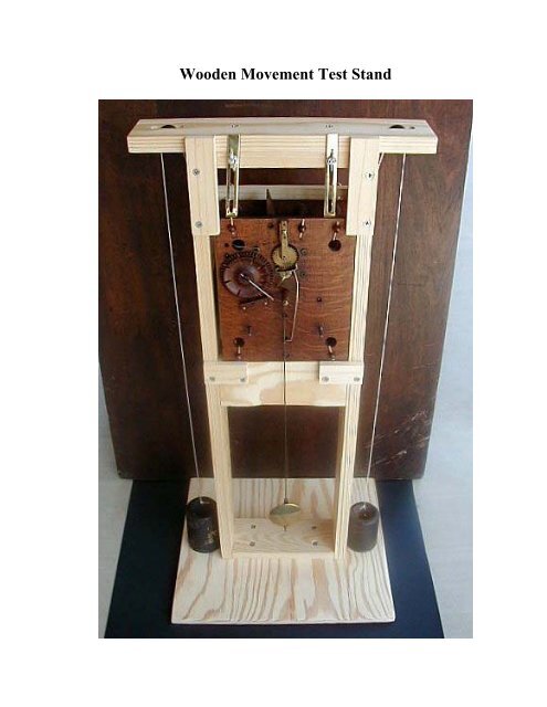
<strong>Wooden</strong> <strong>Movement</strong> Test <strong>Stand</strong>
<strong>Wooden</strong> <strong>Movement</strong> Test <strong>Stand</strong>
<strong>Wooden</strong> <strong>Movement</strong> Test <strong>Stand</strong>
<strong>Wooden</strong> <strong>Movement</strong> Test <strong>Stand</strong><br />
This test stand is based on a design provided by Phil Gregory. Rather than<br />
using brass pins to secure the movement in place, the test stand was<br />
redesigned by Don Bugh and Terry Palmer to use braces as the method for<br />
supporting the movement.<br />
Mary Ellen Bell supplied us with four wooden movements to ensure that the<br />
test stand would accommodate a range of dimensions. The plates of these<br />
movements ranged as follows:<br />
Height –<br />
Width –<br />
Depth –<br />
8 1/16 to 8 1/4 inches<br />
6 3/8 to 6 5/8 inches<br />
2 3/8 to 2 3/4 inches<br />
General construction notes:<br />
a. The clock stand was made from 1 x 4 white pine lumber and<br />
was ripped on a table saw to the required 3 inch widths or<br />
narrower as noted below.<br />
b. All screw holds were countersunk using a countersink drill bit.<br />
c. Pilot holds were drilled for each screw to prevent wood splitting.<br />
1. Base – 14 inches x 12 1/2 inches – made from 1/2 inch plywood.
2. Frame:<br />
Side pieces – 3 inches x 27 3/4 inches<br />
Top and bottom pieces – 3 inches x 6 3/4 inches<br />
Side openings – from top of side piece, mark drill points at 2 1/4<br />
inches from the top (centered) and 17 1/4 inches from the bottom<br />
(centered). Center a 1 1/4 inch wood drill bit on each of the drill<br />
points and drill all four holes. Saw out the remaining portion of the<br />
side openings (a pencil line connecting the outer portions of each of the<br />
drilled holes is helpful in doing this – we used a jig saw).<br />
Note: The slot shown in the accompanying photo is too short – the<br />
dimensions have been revised as shown above.<br />
Make sure frame is square and secure with #10 x 1 1/4 inch screws.<br />
3. Pulley Support Board – 3 inches x 13 1/2 inches<br />
Openings for the two 7/8 inch wooden pulleys (Timesavers #12194).<br />
From each side of the pulley support board, mark drill points at one<br />
inch and two inches from the edge (centered). Center a 1/2 inch drill
it on each of the drill points and drill out all four holes. Saw out the<br />
remaining portions of the openings. (Again, draw a pencil line<br />
connecting the two outer portions of the drill holes before sawing out<br />
the remaining portions.)<br />
The arbors for the pulleys are made from 1/8 inch steel rod (Lowes).<br />
Grind a point on one end. From the back side of the top piece, drill a<br />
1/8 inch hole for the arbor in the center of each of the two pulley<br />
openings. Make sure that the drill is level in order to keep the hole<br />
centered on the opposite side of the opening. Drill through about 1/2<br />
inch on the opposite side.<br />
The pulleys will need to be opened up a bit with a 1/8 inch drill. Make<br />
sure the pulleys spin freely on the arbors before installation. Insert<br />
each arbor and slip on the pulleys. Tap the arbors to seat them in<br />
place. I recommend leaving about 1/2 inch of the arbor remaining in<br />
case it ever needs to be removed.
4. Mount frame on base – Center frame on base and secure with<br />
Four #10 x 1 1/4 inch wood screws (Ensure that the 6 3/4 inch<br />
Section of the frame is parallel to the 14 inch side of the base.<br />
The screws are a bit too long and will need to be cut down a bit to<br />
prevent them from extending through the base.<br />
5. Front Support – 3 inches x 6 3/4 inches wide (from 1 x 4 material).
Sand an indention about 1/8 inch deep into the middle four inches<br />
of the front support. (This will prevent interference of the suspension<br />
rod with the front support piece.) Mark 13 1/2 inches<br />
above the base on each side. Loosely secure the front support to the<br />
frame with 2 - # 10 x 1 1/4 inch wood screws on each side of the frame.<br />
The bottom edge of the front support should line up with this mark.<br />
After partially securing the front support, place<br />
test stand on a level surface. Make sure that the front support is<br />
level – adjust as needed. Complete the installation of the remaining<br />
two #10 x 1 1/4 inch wood screws.<br />
6. Side Supports – 2 1/4 inches wide x 1 1/2 inches high (from 1 x 4<br />
material)<br />
Mount flush with top of front support with two # 10 x 1 1/4 inch<br />
wood screws (Before installing second screw, place test stand on a level<br />
surface and check to make sure side supports are level. Adjust as<br />
needed).
7. Pulley Support Board installation – Center pulley support board on<br />
top frame board and secure with two # 10 x 1 1/4 inch wood screws.<br />
8. Back Brace – Made from a scrap piece of wood 1 1/4 inches high x<br />
8 1/4 inches wide – approximately 3/8 inches thick.<br />
The braces are made from:<br />
2 – Insert nuts (1/4 x 20 x 12.5 mm) Lowes<br />
2 – Connecting bolts (1/4 x 20 x 50 mm) Lowes<br />
2 – Connecting cap nuts (1/4 x 20 x 12 mm) Lowes
The drill point for the insert nuts are at 1 1/4 inch from each end<br />
of the back brace. Drill a 11/32 inch hole at each drill point. (Part<br />
of the insert nut is ground off to make it flush with the thickness<br />
of the back brace. Similarly, about 1/4 inch of the connecting cap<br />
nuts is ground off to allow more travel room for the bolt.)
Tap in the insert nuts and then install the connecting bolts and<br />
caps. Use Loctite to secure nut to bolt. (Cap nut is on inside of<br />
the back brace board.)<br />
Mark 3 1/2 inches down from the top on each side of the frame.<br />
Mount back brace such that the top of the brace is even with the<br />
mark. Install with two - # 8 x 1 inch wood screws.<br />
9. Upper Front Brace – made from two scrap pieces 1 1/4 inches wide x 4<br />
1/2 inches high – approximately 3/8 inches thick.
Mount the braces with 2 - # 8 x 1 inch wood screws on the left and<br />
right sides of the frame such that a lip is formed of approximately<br />
1/8 inch to 3/16 inch.<br />
The upper and lower braces prevent the movement from slipping<br />
forward.
10. Lower Front Braces – made from two scrap pieces 1 1/4 inches x<br />
2 ¼ inches – approximately 3/8 inches thick.<br />
Install with two - # 8 x 1 inch wood screws such that a bottom lip<br />
is formed of approximately 1/8 inch to 3/16 inch.
11. Top Braces (Brass) – As nothing commercially could be found,<br />
these two brass braces were custom made from a piece of<br />
.064 x 1/2 inch brass strips (K & S Engineering – purchased at a<br />
local hobby shop).<br />
Cut two strips 4 ¾ inches long. Insert each strip into a vise<br />
leaving a little more than 3/4 inches exposed. Bend that portion<br />
to form a 90 degree angle.<br />
In each strip, cut a slot beginning about 5/16 th of an inch from the<br />
“L” end of the brace ending about one inch from the remaining side.
Drill a 3/16 th inch hole at each end of the marked slot. Scribe<br />
parallel lines to join the outer edges of the two drilled holes. Using a<br />
jeweler’s saw, cut along the scribed lines to complete the slot. The<br />
slot should be about 3/16 th of an inch wide and should clear the<br />
threaded ends of an 8-32 hanger bolt. File the slot edges<br />
smooth. Polish and lacquer the brass to prevent tarnishing.<br />
Center and install two # 8-32 x 1 inch hanger bolts (Lowes)<br />
approximately two inches from the edges of the top frame board (not<br />
the pulley support board that is above the top frame board).<br />
Place a washer on each of the hanger bolts, followed by the brass<br />
brace, another washer and finally an 8-32 wing nut (Lowes).
This test stand is still a work in progress. If you have any<br />
questions, you may contact Don Bugh at 979-690-2736 or<br />
email at d-bugh@cox.net<br />
Any suggestions for improving this design will be<br />
appreciated.<br />
Good luck!<br />
Don Bugh<br />
College Station, TX<br />
June 9, 2006
<strong>Wooden</strong> <strong>Movement</strong> Test <strong>Stand</strong><br />
On Display at the April, 2006<br />
Great Southwestern Regional<br />
Chapter 15 -- Kerrville, TX