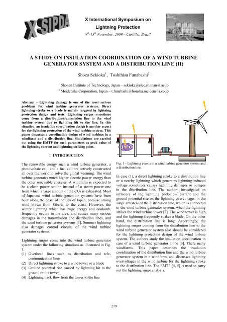
A STUDY ON INSULATION COORDINATION OF A WIND TURBINE ...
A STUDY ON INSULATION COORDINATION OF A WIND TURBINE ...
A STUDY ON INSULATION COORDINATION OF A WIND TURBINE ...

Create successful ePaper yourself
Turn your PDF publications into a flip-book with our unique Google optimized e-Paper software.
X International Symposium on<br />
Lightning Protection<br />
9 th -13 th November, 2009 – Curitiba, Brazil<br />
A <strong>STUDY</strong> <strong>ON</strong> INSULATI<strong>ON</strong> COORDINATI<strong>ON</strong> <strong>OF</strong> A <strong>WIND</strong> <strong>TURBINE</strong><br />
GENERATOR SYSTEM AND A DISTRIBUTI<strong>ON</strong> LINE (II)<br />
Shozo Sekioka 1 , Toshihisa Funabashi 2<br />
1 Shonan Institute of Technology, Japan – sekioka@elec.shonan-it.ac.jp<br />
2 Meidensha Corporation, Japan – t.funabashi@honsha.meidensha.co.jp<br />
Abstract - Lightning damage is one of the most serious<br />
problems for wind turbine generator systems. Direct<br />
lightning stroke to a blade is mainly targeted in lightning<br />
protection design and tests. Lightning surges sometimes<br />
come from a distribution/transmission line to the wind<br />
turbine system due to lightning hit to the line. In this<br />
situation, an insulation coordination design is another aspect<br />
for the lightning protection of the wind turbine system. This<br />
paper discusses a coordination design of wind turbines in a<br />
windfarm and a distribution line. Simulations are carried<br />
out using the EMTP for such parameters as peak value of<br />
the lightning current and lightning striking point.<br />
1 INTRODUCTI<strong>ON</strong><br />
The renewable energy such a wind turbine generator, a<br />
photovoltaic cell, and a fuel cell are actively constructed<br />
all over the world to solve the global warming. The wind<br />
turbine generates much higher electric power energy than<br />
the other renewable energies. A windfarm is expected to<br />
be a clean power station instead of a steam power one<br />
from which a large amount of the CO 2 is exhausted. Most<br />
of Japanese wind turbine generator systems have been<br />
built along the coast of the Sea of Japan, because strong<br />
wind blows from Siberia to the coast. However, the<br />
winter lightning which has huge energy and coulomb,<br />
frequently occurs in the area, and causes many serious<br />
damages in the transmission and distribution lines, and<br />
the wind turbine generator systems [1]. Summer lightning<br />
also damages control circuits of the wind turbine<br />
generator systems.<br />
Lightning surges come into the wind turbine generator<br />
system under the following situations as illustrated in Fig.<br />
1.<br />
(1) Overhead lines such as distribution and telecommunication<br />
lines<br />
(2) Direct lightning stroke to a wind tower or a blade<br />
(3) Ground potential rise caused by lightning hit to the<br />
ground or the tower<br />
(4) Lightning back flow from the tower to the line<br />
Fig. 1 - Lightning events in a wind turbine generator system and<br />
a distribution line.<br />
In case (1), a direct lightning stroke to a distribution line<br />
or a nearby lightning which generates lightning-induced<br />
voltage sometimes causes lightning damages or outages<br />
in the distribution line. The authors investigated an<br />
influence of the lightning back-flow current and the<br />
ground potential rise on the lightning overvoltages in the<br />
surge arresters of the distribution line, which is connected<br />
to the wind turbine generator system, when the lightning<br />
strikes the wind turbine tower [2]. The wind tower is high,<br />
and the lightning frequently strikes a blade. On the other<br />
hand, the distribution line is long. Accordingly, the<br />
lightning surges coming from the distribution line to the<br />
wind turbine generator system also should be considered<br />
for the lightning protection design of the wind turbine<br />
system. The authors study the insulation coordination in<br />
case of a wind turbine generator alone [3]. There many<br />
windfarms. This paper describes the insulation<br />
coordination of the distribution line and the wind turbine<br />
generator system in a windfarm, and discusses lightning<br />
overvoltages in the wind turbine for the lightning stroke<br />
to the distribution line. The EMTP [4, 5] is used to carry<br />
out the lightning surge analysis.<br />
279
G<br />
G<br />
Zp<br />
Zp<br />
Zp<br />
Zp<br />
Ra<br />
Ra<br />
Ra<br />
Ra<br />
R<br />
R<br />
Fig. 2 - Simulation circuit.<br />
2 SIMULATI<strong>ON</strong> CIRCUIT<br />
2.1 Simulation Circuit for Direct Lightning Stroke to<br />
a Distribution Line<br />
Fig. 2 illustrates a simulation circuit to estimate lightning<br />
overvoltages in a wind turbine generator system in a<br />
windfarm for a direct lightning stroke to a shielding wire<br />
of a distribution line. Table 1 shows specifications of a<br />
transformer, which is used in [6]. The wind turbines and<br />
the cables in the windfarm have the same specifications.<br />
Table 1: specifications of transformer [6].<br />
Connection method<br />
Y-∆<br />
Rating power<br />
1.0 MVA<br />
Rating voltage<br />
600/6,600 V<br />
Frequency<br />
60 Hz<br />
% impedance 15.7 %<br />
Mutual leakage inductance<br />
18.2 mH<br />
2.2 Simulation Models<br />
(a)Distribution line<br />
The Dommel model [7] and the J.Marti model [8] are<br />
available in the EMTP. The Dommel model deals with<br />
line constants for only single frequency, and shows<br />
poorer accuracy than the J.Marti model, which can take<br />
the frequency dependence into account. Therefore, this<br />
paper adopts the J.Marti model for the distribution line<br />
and the service line.<br />
The length of the overhead line is 1 km. The distribution<br />
line is terminated by matching circuit at an end of the line<br />
to represent semi infinite length of line. The length<br />
between poles and a transformer is 40m. Fig. 3 illustrates<br />
a configuration of the distribution and service lines.<br />
1 m<br />
0.7m 0.7m<br />
Ground wire (standard steel wire<br />
22 mm 2 )<br />
Medium voltage line<br />
ACSR OC 32 mm 2<br />
11m<br />
CVT 22 mm 2<br />
0.6 m<br />
(a) Distribution line (b) Service line<br />
Fig.3 - Arrangement of the distribution and service lines.<br />
(b) Vertical conductors<br />
A wind turbine is usually mounted at the top of a wind<br />
tower to directly connect to a rotor. A reinforced concrete<br />
pole is equivalent to a metallic pipe for lightning surges<br />
based on experimental study [9]. The wind turbine is<br />
connected to a transformer or an inverter through a 3-<br />
phase power cable. As a result, 4 parallel vertical<br />
conductors exist in the wind tower as illustrated in Fig. 4.<br />
This paper considers a CVT cable of 22mm 2 as the power<br />
cable in the tower and a copper pipe with radius r TW of<br />
1.6 m as the wind tower.<br />
h'<br />
r TW<br />
Fig - 4 Configuration of a wind tower and a power cable<br />
to obtain conductor constants.<br />
r c<br />
r s<br />
The self- and mutual surge impedances Z 0s and Z 0m of<br />
280
vertical conductors are given by [10]<br />
h<br />
Z0 s = 60ln<br />
(1)<br />
e⋅<br />
r<br />
h<br />
Z0 m = 60ln<br />
(2)<br />
e⋅<br />
d<br />
where h is the conductor height, r is the conductor radius,<br />
d is the distance between centers of the conductors, and e<br />
is the base of natural logarithm.<br />
Line constants of the vertical conductors can be obtained<br />
by using CABLE C<strong>ON</strong>STANTS [11], which is a<br />
subprogram in the EMTP. The conductor height h’ for the<br />
vertical conductors used in the subprograms is replaced<br />
by 0.5h/e [12], and the distance between the conductors<br />
in the subprograms is the same as that of the actual<br />
configuration. The Dommel model is used for the vertical<br />
conductors in this paper because of short conductor<br />
length.<br />
(c) Surge arrester<br />
Surge arresters of the distribution line are installed on odd<br />
number reinforced concrete poles. The arresters in the<br />
high-voltage side of the transformer are not considered in<br />
this paper. The distribution line arrester at the end of the<br />
lone is located close to the transformer, and is expected to<br />
protect the high-voltage side on the transformer. Lowvoltage<br />
side arresters must be considered because direct<br />
lightning stroke to the wind tower often causes lightning<br />
overvoltages and damages in the wind turbine generator<br />
system. The arrester is represented by a series circuit of a<br />
voltage-controlled switch and a nonlinear resistance,<br />
which is given by current-voltage characteristics.<br />
Operation voltage of the distribution line arresters is 29<br />
kV. Voltage-current curves of the arresters are shown in<br />
Fig. 6. Surge protective devices for low-voltage circuit<br />
are not simulated in this paper.<br />
Voltage [kV]<br />
25<br />
20<br />
15<br />
10<br />
5<br />
High-voltage Ar<br />
Low-voltage Ar<br />
0<br />
1.E-03 1.E-02 1.E-01 1.E+00 1.E+01 1.E+02 1.E+03 1.E+04<br />
Current [A]<br />
Fig. 5 - Voltage - current curve of the surge arresters.<br />
(d) Transformer<br />
Transformer is frequently represented by capacitances for<br />
lightning surge analysis when the analysis is targeted only<br />
for the high voltage line. However, this simple model<br />
cannot deal with secondary transition voltages. Therefore,<br />
this paper adopts an accurate transformer model, which<br />
considers the secondary voltage and high frequency<br />
characteristics [13, 14]. Fig. 6 shows measured<br />
capacitances of Y-∆ transformers [14]. Capacitances of a<br />
transformer can be approximated by a simple function of<br />
rated capacity [15]. Thus, the capacitances are estimated<br />
by approximate lines included in Fig. 6.<br />
Capacitance [nF/phase]<br />
10<br />
0.1<br />
High-voltage winding to ground<br />
∆ Low-voltage winding to ground<br />
High- and low-voltage windings<br />
1<br />
1 10 100<br />
Rated capacity [MVA]<br />
Fig. 6 - Measured results of capacitances of transformers and<br />
approximate characteristics.<br />
Now, the rated capacity is 1 MVA form Table 1.<br />
Capacitances between high-voltage windings and the<br />
ground and between low-voltage windings and ground<br />
are 500 pF, and that between low- and high-voltage<br />
windings 1000 pF.<br />
(e) Generator<br />
A generator for lightning surges analysis can be modeled<br />
by reactance and capacitance [16]. This paper represents<br />
the generator by capacitance for simplicity. The<br />
capacitance between a phase winding and the wind tower<br />
is considered.<br />
(f) Grounding system<br />
Reinforced concrete poles are used in the Japanese<br />
distribution lines to sustain wires and power apparatuses.<br />
The reinforced concrete pole should be treated as a<br />
grounding lead conductor and a grounding electrode in<br />
lightning performance [12, 17]. The grounding system of<br />
the distribution line is represented by a distributedparameter<br />
line, and a grounding resistance. The surge<br />
velocity in the reinforced concrete pole is equal to the<br />
velocity of light in free space. The grounding resistance<br />
shows current dependence for high currents. This paper<br />
does not consider the soil ionization [18] as well as<br />
frequency dependence.<br />
The ground wire is grounded at the each pole. The<br />
grounding resistance R a for the surge arresters and the<br />
ground wire is 30 Ω. The surge impedance Z p of the<br />
reinforced concrete pole is 200 Ω [19].<br />
281
The grounding electrodes and the tower bases of wind<br />
turbines are connected using a grounding conductor. Low<br />
steady-state grounding resistance can be obtained using<br />
the grounding conductor. Propagation characteristics of<br />
the grounding conductor are quite different from those of<br />
an insulated conductor because of the existence of shunt<br />
conductance [20]. Voltages on the grounding conductor<br />
are attenuated and deformed along the conductor.<br />
Lightning current has short wavefront duration, and peak<br />
voltage often appears before reflection voltage from the<br />
receiving end of the grounding conductor reaches.<br />
Therefore, effective length, which is defined as the length<br />
above which no further reduction of impedance of a<br />
grounding conductor is observed, should be considered to<br />
prevent the wind turbines from lightning-caused damages<br />
[21].<br />
Fig. 7 shows an equivalent circuit of a horizontal<br />
grounding conductor, where Z 0 is the surge impedance of<br />
the loss-less line, v is the surge velocity on the line, and<br />
∆x is the elementary length of the equivalent circuit. The<br />
circuit is composed of shunt conductances due to finite<br />
soil resistivity and a loss-less line [20]. The grounding<br />
conductor is represented by a ladder circuit of the<br />
equivalent circuit. The steady-state grounding resistance<br />
R 0 of the grounding conductor is given by<br />
−1<br />
0 = ( Gl)<br />
R (3)<br />
where G is the shunt conductance per length.<br />
The surge impedance and the propagation velocity of the<br />
grounding conductor are 100 Ω, and 100 m/µs<br />
respectively.<br />
Z0, v, ∆x Z0, v, ∆x<br />
G∆x k G∆x k+1 G∆x<br />
Fig. 7 - An equivalent circuit of a long grounding conductor.<br />
(g) Lightning current<br />
The lightning current waveform is assumed to be a ramp<br />
shape of 2/70 µs, which is the simplest model for summer<br />
lightning. The lightning is represented by a parallel circuit<br />
of a current source and a lightning channel impedance of<br />
1 kΩ. Lightning current is injected into the top of a<br />
reinforced concrete pole.<br />
2.3 Simulation Conditions<br />
This paper investigates an influence of the following<br />
parameters on lightning overvoltages on a wind turbine<br />
generator system. Standard values are shown in Table 2.<br />
The grounding resistance of the wind turbine generator<br />
system is often chosen to be 2 Ω. That for a lightning rod<br />
is 10 Ω. This paper adopts 10 as a standard value. The<br />
grounding resistance is 1, 2, 5, and 10 Ω. The transformer<br />
is assumed to be set on the same base of the wind tower,<br />
and the grounding of the transformer is common with the<br />
wind tower.<br />
This paper investigates influence of grounding system of<br />
a wind turbine generator system on lightning overvoltages.<br />
Five wind turbines are considered.<br />
3 SIMULATI<strong>ON</strong> RESULTS<br />
3.1 Single Wind Turbine Generator System<br />
Fig.8 shows calculated results of peak value of lightning<br />
overvoltages on single wind turbine generator for a<br />
parameter of the grounding resistance R TB of the wind<br />
turbine generator system. Voltage is defined by potential<br />
difference between the observation point and the<br />
grounding system.<br />
Voltage [kV]<br />
5<br />
4<br />
3<br />
2<br />
1<br />
0<br />
Table 2: standard values in simulation parameters.<br />
Grounding<br />
Striking Lightning<br />
Generator<br />
Resistance of<br />
point Current<br />
capacitance<br />
Wind Turbine<br />
1 st pole 25 kA 10 Ω 10 nF<br />
cable sending end<br />
cable receiving end<br />
Tr secondary potential<br />
1 10 100<br />
Grounding resistance [Ω]<br />
Fig. 8 - Calculated results of peak voltage for a parameter of<br />
grounding resistance R TB .<br />
From Fig. 8, the potential in the wind turbine generator<br />
system increases as the grounding resistance R TB becomes<br />
higher, because the ground potential rises. This potential<br />
corresponds to the voltage in the telecommunication<br />
equipment. The other voltages are independent of the<br />
grounding resistance. Therefore, the grounding resistance<br />
affects only potential rise for the lightning overvoltages<br />
coming from the distribution line.<br />
Fig. 9 shows calculated waveforms in case of R TB =10 Ω<br />
and 100 Ω.<br />
50<br />
40<br />
30<br />
20<br />
10<br />
0<br />
Potential [kV]<br />
282
40<br />
30<br />
20<br />
5<br />
4<br />
cable sending-end voltage<br />
cable receiving-end voltage<br />
X Tr secondary potential<br />
50<br />
40<br />
Potential [kV]<br />
10<br />
0<br />
‐10<br />
‐20<br />
0 10 20 30 40 50<br />
Time [µs]<br />
Voltage [kV]<br />
3<br />
2<br />
1<br />
30<br />
20<br />
10<br />
Potential [kV]<br />
‐30<br />
‐40<br />
(a) Potential<br />
Voltage [kV]<br />
4<br />
3<br />
2<br />
1<br />
0<br />
‐2<br />
‐3<br />
‐4<br />
10 Ω<br />
100Ω<br />
0 10 20 30 40 50<br />
‐1<br />
Time [µs]<br />
10 Ω<br />
100Ω<br />
(b) Voltage<br />
Fig. 9 - Calculated waveforms on single wind turbine<br />
generator.<br />
From Fig. 9, the voltage waveforms are not affected by<br />
the grounding resistance.<br />
3.2 Wind Turbine Generator System in Windfarm<br />
Figs. 10 and 11 show calculated results of peak value of<br />
the lightning overvoltages for a parameter of the<br />
grounding resistance R CG of the grounding conductor in<br />
case of R TB =10 and 100 Ω. The values for R CG =0 Ω and<br />
100 Ω are results of single turbine and no grounding<br />
conductor, respectively.<br />
Voltage [kV]<br />
5<br />
4<br />
3<br />
2<br />
1<br />
0<br />
cable sending-end voltage<br />
cable receiving-end voltage<br />
X Tr secondary potential<br />
0 20 40 60 80 100<br />
Grounding resistance [Ω]<br />
Fig. 10 - Calculated results of peak voltage for a parameter of<br />
grounding resistance R CG (R TB =10 Ω).<br />
10<br />
8<br />
6<br />
4<br />
2<br />
0<br />
Potential [kV]<br />
0<br />
0 20 40 60 80 100<br />
Grounding resistance [Ω]<br />
Fig. 11 - Calculated results of peak voltage for a parameter of<br />
lightning current (100 Ω).<br />
It is clear from Figs. 10 and 11, the grounding resistance<br />
R CG does not affect the voltage on the wind turbine. The<br />
potential is reduced by using the grounding conductor.<br />
Fig. 12 shows calculated waveforms of the voltage on the<br />
first, third and fifth wind turbines in cases of R TB =R CG =<br />
100 Ω.<br />
Voltage [kV]<br />
4<br />
3<br />
2<br />
1<br />
0<br />
0 10 20 30 40 50<br />
‐1<br />
Time [µs]<br />
‐2<br />
‐3<br />
‐4<br />
Fig. 12 - Calculated waveforms of the voltage on first, third<br />
and fifth wind turbines.<br />
Fig. 12 shows that significant difference is not observed<br />
among the wind turbines.<br />
Fig. 13 shows calculated waveforms in cases that the<br />
grounding resistance R CG is 10 Ω and 100 Ω when R TB is<br />
100 Ω.<br />
4 C<strong>ON</strong>CLUSI<strong>ON</strong><br />
This paper has discussed lightning overvoltages on wind<br />
turbines in a windfarm for a direct lightning stroke to a<br />
distribution line. The simulation results using the EMTP<br />
show that the grounding resistance of the wind turbine<br />
generator system does not affect the lightning overvoltages,<br />
but the potential increases as the grounding<br />
resistance becomes higher.<br />
5 REFERENCES<br />
0<br />
283
Potential [kV]<br />
8<br />
6<br />
4<br />
2<br />
0<br />
<br />
‐2<br />
Time [µs]<br />
‐4<br />
‐6<br />
‐8<br />
(a) Potential<br />
Voltage [kV]<br />
4<br />
3<br />
2<br />
1<br />
0<br />
‐2<br />
‐3<br />
‐4<br />
10 Ω<br />
100Ω<br />
<br />
‐1<br />
Time [µs]<br />
10 Ω<br />
100Ω<br />
(b) Voltage<br />
Fig. 13 - Calculated waveforms on wind turbines in<br />
windfarm.<br />
[1] S. Sekioka, K. Yamamoto, M. Minowa, and S. Yokoyama,<br />
“Damages in Japanese wind turbine generator<br />
systems due to winter lightning”, Proceeding of<br />
International Symposium on Lightning Protection, pp. 186-<br />
191, Foz do Iguaçu, Brazil, Nov. 2007.<br />
[2] H. Okamoto, S. Sekioka, Y. Ebinuma, K. Yamamoto, Y.<br />
Yasuda, T. Funabashi, and S. Yokoyama, “Energy<br />
absorption of distribution line arresters due to lightning back<br />
flow current and ground potential rise for lightning hit to<br />
wind turbine generator system”, IEEJ Trans., Vol. 129-B,<br />
No. 7, pp. 668-674, July 2009.<br />
[3] S. Sekioka, and T. Funabashi, “A study on insulation<br />
coordination of a wind turbine generator system and a<br />
distribution line”, CIGRE Colloquium, S2-5, Kushiro, Japan,<br />
June 2009.<br />
[4] W. S. Meyer, EMTP Rule Book, BPA, 1984.<br />
[5] H. W. Dommel, Electromagnetic transients program<br />
reference manual (EMTP theory book), BPA, 1986.<br />
[6] Y. Yasuda, T. Hara, and T. Funabashi, ”Analysis on<br />
lightning surge propagation in wind farm”, IEEJ Trans., Vol.<br />
125-B, No. 7, pp. 709-716, 2005 (in Japanese).<br />
[7] H. W. Dommel, "Digital computer solution of electromagnetic<br />
transients in single- and multiphase networks",<br />
IEEE Trans. Power Apparatus and Systems, Vol. 88, No. 4,<br />
pp. 388-397, 1969.<br />
[8] J. R. Marti, “Accurate modelling of frequency-dependent<br />
transmission lines in electromagnetic transient simulations”,<br />
ibid. Power Apparatus and Systems, Vol. 101, No. 101, pp.<br />
147-157, 1982.<br />
[9] K. Yamamoto, Z. Kawasaki, K. Matsuura, S. Sekioka, and S.<br />
Yokoyama, “Study on surge impedance of reinforced<br />
concrete pole and grounding lead wire on distribution lines<br />
by experiment on reduced scale model”, in Proc. of 10 th Int.<br />
Symp. on High Voltage Engineering, Vol. 5, pp. 209-212,<br />
Montreal, Canada, 1997.<br />
[10]A. Ametani, Y. Kasai, J. Sawada, A. Mochizuki, and T.<br />
Yamada, "Frequency-dependent impedance of vertical<br />
conductors and a multiconductor tower model," IEE Proc.-<br />
GTD, Vol. 141, No. 4, pp. 339-345, 1994.<br />
[11]A. Ametani, "A general formulation of impedance and<br />
admittance of cables," IEEE Trans. Power Apparatus and<br />
Systems, Vol. 99, No. 3, pp. 902-910, 1980.<br />
[12]S. Sekioka, “Lightning surge analysis model of reinforced<br />
concrete pole and grounding lead conductor in distribution<br />
line”, IEEJ Trans. Electrical and Electronic Engineering,<br />
Vol. 3, pp. 432-440, 2008.<br />
[13]T. Ueda, T. Sugtimoto, T. Funabashi, N. Takeuchi, T. Sato,<br />
and K. Miyagi, “A study on transformer model for transfer<br />
voltages considering frequency characteristics”, IEEJ Trans.,<br />
Vol. 117-B, No. 9, pp. 1294-1300, 1997 (in Japanese).<br />
[14]T. Funabashi, “A study on modeling technique for power<br />
system transients analysis”, Thesis for Doctor Degree, 1999.<br />
[15]A. Greenwood, Electrical transients in power systems,<br />
Second edition, John Wiley & Sons, Inc., 1991.<br />
[16]T. Funabashi, N. Takeuchi, T. Sugtimoto, T. Ueda, L. Dube,<br />
and A. Ametani, “Generator modeling for transformer<br />
transfer voltage study”, IEEE Trans. Energy Conversion,<br />
Vol. 14, No. 4, pp. 1193-1198, 1999.<br />
[17]T. Miyazaki, S. Okabe, and S. Sekioka, “An experimental<br />
validation of lightning performance in distribution lines”,<br />
ibid. Power Delivery, Vol. 23, No.4, pp. 2182-2190, 2008.<br />
[18]S. Sekioka, T. Sonoda, and A. Ametani, "Experimental<br />
study of current-dependent grounding resistances of rod<br />
electrode," ibid. Trans. Power Delivery, Vol. 20, No. 2, pp.<br />
1569-1576, 2005.<br />
[19]K. Nakada, T. Yokota, S. Yokoyama, A. Asakawa, M.<br />
Nakamura, H. Taniguchi, and A.Hashimoto, “Energy<br />
absorption of surge arresters on power distribution lines due<br />
to direct lightning strokes - Effects of an overhead ground<br />
wire and installation position of surge arresters-”, ibid.<br />
Trans. Power Delivery, Vol. 12, No. 4, pp. 1779-1785, 1997.<br />
[20]S. Sekioka, M. I. Lorentzou, and N.D. Hatziargyriou, “A<br />
simplified formula of surge characteristics of a long<br />
grounding conductor,” Proc. of International Conference on<br />
Power Systems Transients, 7-2, New Orleans, USA, Sep.<br />
2003.<br />
[21]S. Sekioka, and T. Funabashi, “A study on effective length<br />
of long grounding conductor in windfarm”, Trans. IEE of<br />
Japan, Vol. 129-B, No. 7, pp. 675-681, July 2009 (in<br />
Japanese).<br />
284