VA125…: Thermal drive for unit valves, with stroke indicator
VA125…: Thermal drive for unit valves, with stroke indicator
VA125…: Thermal drive for unit valves, with stroke indicator

You also want an ePaper? Increase the reach of your titles
YUMPU automatically turns print PDFs into web optimized ePapers that Google loves.
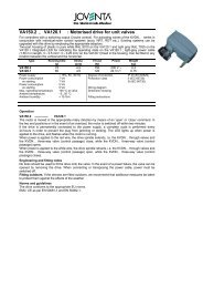
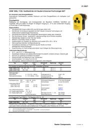
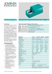
<strong>VA125…</strong>: <strong>Thermal</strong> <strong>drive</strong> <strong>for</strong> <strong>unit</strong> <strong>valves</strong>, <strong>with</strong> <strong>stroke</strong> <strong>indicator</strong><br />
For controllers <strong>with</strong> switched output (2-point). Used in conjunction <strong>with</strong> individual-room control systems<br />
(TSO, NRT, RDT, ecos, ecolon) <strong>for</strong> activating <strong>valves</strong> of the KVDN…. series. Suitable <strong>for</strong> use <strong>with</strong><br />
adaptors to upgrade existing systems. Position <strong>indicator</strong> in the <strong>drive</strong>’s housing.<br />
Pure white housing (as per RAL 9010) of fire-retardant plastic. Can be changed from ‘normally closed’<br />
to ‘normally open’ by removing a special piece. Fitted to valve <strong>with</strong> thread M30×1.5. Fitting position:<br />
vertical to horizontal. White power cable of Ø 0.5 mm 2 or 0.75 mm 2 , fixed to the housing. Standard<br />
version has 1.2 m of cable.<br />
Type<br />
Running<br />
time 1)<br />
min<br />
Max.<br />
<strong>stroke</strong><br />
[mm]<br />
Spring<br />
pressure<br />
[N]<br />
Normally Power Weight<br />
[kg]<br />
Actuator <strong>with</strong> bayonet connection<br />
VA125.2 3 4.5 125 closed (open) 230 V~ 0.2<br />
VA125.1 3 4.5 125 closed (open) 24V~/= 0.2<br />
Drives <strong>with</strong> in-built auxiliary contacts 3) and bayonet connection<br />
VA125.2S 3 4.5 125 closed 230 V~ 0.2<br />
VA125.1S 3 4.5 125 closed 24V~/= 0.2<br />
Power supply 230 V~ ± 15%. 50...60 Hz Degree of protection IP 42 (EN 60529)<br />
24 V~/= ± 20%, 50...60 Hz <strong>with</strong> auxiliary contacts IP 44 (EN 60529)<br />
Y07549<br />
Power consumption 230 V 24 V<br />
in operation 2.5 W 3 W<br />
on starting 36 W 6 W<br />
start-up current 150 mA 250 mA<br />
Max. operating temp. 100°C at valve<br />
Ambient temperature –5...50 °C<br />
Ambient humidity < 95 %rh<br />
3) Auxiliary contacts 5(2) A, 230 V; cut-in point 1.5 mm, <strong>stroke</strong> ± 0.75 mm<br />
Y10020
Operation<br />
The actuator has an electrically heated, overrun-proof expansion element which transfers its <strong>stroke</strong> direct to the<br />
valve. It works silently and requires no maintenance.<br />
When the heating element is switched on from cold, the valve (after a warming-up time of about 1.3 minutes)<br />
starts to open and has per<strong>for</strong>med 3 mm of <strong>stroke</strong> after approx. 1.7 minutes. The closing operation is symmetrical<br />
(<strong>with</strong> regard to time) to the opening operation: the expansion element cools down and the valve is closed by<br />
spring pressure. The <strong>drive</strong>’s direction of operation can be changed by removing a special piece and then turning<br />
a screw.<br />
‘Normally closed’ (factory setting):-<br />
• Drive has power applied: valve <strong>with</strong> pushing plug (as types KVDN….), from closed to open.<br />
• Drive has power applied: valve <strong>with</strong> hanging plug (as type KVDN….), from open to closed.<br />
‘Normally open’ (piece removed):-<br />
• Drive has power applied: valve <strong>with</strong> pushing plug (as type KVDN….), from open to closed.<br />
• Drive has power applied: valve <strong>with</strong> hanging plug (as type KVDN….), from closed to open.<br />
With a ‘pulse-pause’ clock signal, which effects a periodic open/close position, a quasi-continuous control system<br />
can be achieved <strong>with</strong> a cycle duration of 4 minutes. Permissible cycle duration: either < 4 min or > 12 min. Using the<br />
auxiliary contacts (which are available as an accessory and can be fitted later), a circulation pump or a heat counter,<br />
<strong>for</strong> instance, can be switched on.<br />
The auxiliary contacts switch between 35% and 50% <strong>stroke</strong>. The rating <strong>for</strong> these auxiliary contacts is 3 A <strong>for</strong> ohmic<br />
load and 2 A <strong>for</strong> inductive load. The contacts close when the <strong>stroke</strong> reaches 35% or 50%.<br />
Engineering and fitting notes<br />
Be<strong>for</strong>e choosing the switching contacts and the mains fuses, the inrush current of the heating element should be<br />
taken into account. To ensure that the given running time can be achieved, the voltage loss in the electric cables<br />
should not exceed 10%.<br />
The way to change from ‘normally closed’ to ‘normally open’ is described . The position <strong>indicator</strong> shows which<br />
function has been set. When the red <strong>indicator</strong> is inserted in a black plastic piece, the ‘normally closed’ function is<br />
activated. When the red <strong>indicator</strong> is inserted in a white plastic piece, the ‘normally open’ setting is active.<br />
On the ‘normally closed’ standard version, the valve can, in the event of a power failure, be opened by removing<br />
the <strong>drive</strong>. No tools should be used to fit the actuator to the valve: turning by hand is quite sufficient.<br />
Fitting outdoors. If the devices are fitted outdoors, we recommend that additional measures be taken to protect<br />
them against the effects of the weather.<br />
Standards and regulations<br />
The actuator is tested to the requisite standards and complies <strong>with</strong> the relevant EU regulations.<br />
Additional technical data<br />
Rating of auxiliary switch when used <strong>with</strong> direct current: 4...30 V, 1...100 mA<br />
VA125.1 , VA125.2<br />
VA125.1M<br />
Complies <strong>with</strong>:-<br />
Complies <strong>with</strong>:-<br />
Directive 73/23/EEC EN 60730-1/ EN 60730-2-14 EMC directive 89/336/EEC EN 61000-6-1/ EN 61000-6-2<br />
EMC directive 89/336/EEC EN 61000-6-1/ EN 61000-6-2 EN 61000-6-3/ EN 61000-6-4<br />
EN 61000-6-3/ EN 61000-6-4<br />
Wiring diagram<br />
371557<br />
BK RD WH<br />
BN<br />
BU<br />
AXT111<br />
BN<br />
BU<br />
BK<br />
BK<br />
AXT111F210<br />
AXT111F212<br />
VUL<br />
VXL<br />
R<br />
NC NO<br />
( )<br />
( )<br />
A09778<br />
BN = brown<br />
BU = blue<br />
BK = black<br />
RD = red<br />
WH = white<br />
R<br />
VUL<br />
VXL<br />
BXL<br />
NC<br />
BUL<br />
BXL<br />
BUL<br />
A10006a<br />
A08924c
Dimension drawing<br />
NC<br />
NO<br />
M30×1,5<br />
38,5<br />
11<br />
Ø 45<br />
52<br />
63,5<br />
NC<br />
Stromlos "zu"<br />
"Fermé" sans tension<br />
normally closed<br />
NO<br />
Stromlos "offen"<br />
"Ouvert" sans tension<br />
normally open<br />
24<br />
Ø 34<br />
M08925b<br />
11,5<br />
23<br />
M30×1,5<br />
Ø44,8<br />
64,8<br />
2<br />
7,5<br />
Ø42,5<br />
7,1<br />
M10083<br />
Ø45<br />
M30×1,5<br />
11,5<br />
2<br />
7,5<br />
63,3<br />
Ø42,5<br />
7,1<br />
M10414