Lab 5 Motor Torque, Speed, Losses and Efficiency - Department of ...
Lab 5 Motor Torque, Speed, Losses and Efficiency - Department of ...
Lab 5 Motor Torque, Speed, Losses and Efficiency - Department of ...

Create successful ePaper yourself
Turn your PDF publications into a flip-book with our unique Google optimized e-Paper software.
ELECTRICAL AND COMPUTER ENGINEERING<br />
THE CITADEL<br />
ELEC 302 <strong>Lab</strong> 5<br />
<strong>Motor</strong> <strong>Torque</strong>, <strong>Speed</strong>, <strong>Losses</strong>, <strong>and</strong> <strong>Efficiency</strong><br />
REFERENCE: Appropriate chapters <strong>of</strong> ELEC 316 text.<br />
OBJECTIVE: The objective <strong>of</strong> this experiment is to familiarize the student with the operation <strong>of</strong> the Prime<br />
Mover/Dynamometer module to measure motor torque, speed, power, <strong>and</strong> efficiency.<br />
EQUIPMENT: Power Supply Module (0-120Vdc) EMS 8821<br />
Prime Mover/ Dynamometer Module (1) EMS 8960<br />
Prime Mover/ Dynamometer Module (2) EMS 8960<br />
Data Acquisition Interface (DAI) EMS 9062<br />
DAI 24V Power Supply EMS 30004<br />
INTRODUCTION:<br />
In this experiment, you will use two Prime Mover/ Dynamometer modules to measure torque, speed, power, <strong>and</strong><br />
efficiency <strong>of</strong> a DC motor. The experiment will be conducted in three parts. The first part will demonstrate operation<br />
<strong>of</strong> the prime mover. The second part will demonstrate the operation <strong>of</strong> the dynamometer. The final part will<br />
demonstrate the measurement <strong>of</strong> motor efficiency.<br />
The Prime Mover module uses a DC motor, <strong>and</strong> operates like a linear voltage to speed converter. A positive voltage<br />
will produce clockwise rotation <strong>of</strong> the motor, the higher the input voltage the faster the motor will turn. The<br />
Dynamometer is a device, which is used to mechanically load the motor <strong>and</strong> measure its output torque <strong>and</strong> speed.<br />
The load control knob on the Dynamometer will vary the mechanical load <strong>of</strong> the device.<br />
In part one <strong>of</strong> the experiment the friction torque <strong>of</strong> the Prime Mover module will be measured. The friction torque is<br />
the twisting force that is experienced by the Prime Mover module when it is rotating without a mechanical load. The<br />
primary components <strong>of</strong> this torque are the friction <strong>of</strong> bearings <strong>and</strong> brushes <strong>of</strong> the DC motor, <strong>and</strong> the windage friction<br />
resulting from the air resistance <strong>of</strong> the rotor. When the Dynamometer is coupled to the Prime Mover module the<br />
torque on the Prime Mover increases due to the addition <strong>of</strong> belt friction <strong>and</strong> machine torque caused by the resistance<br />
<strong>of</strong>fered by the Dynamometer.<br />
A motor experiences both electrical losses <strong>and</strong> mechanical losses. Because <strong>of</strong> these losses, the mechanical output<br />
power <strong>of</strong> the motor is always less than the input electrical power.<br />
PRIOR PREPARATION:<br />
Complete the following at a time determined by the laboratory instructor.<br />
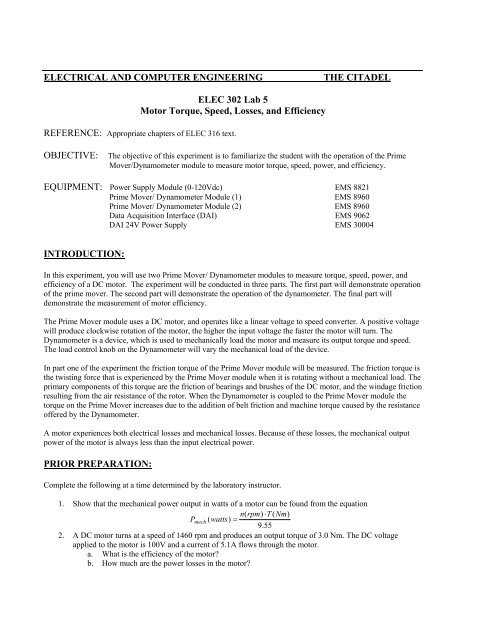
1. Show that the mechanical power output in watts <strong>of</strong> a motor can be found from the equation<br />
n(<br />
rpm)<br />
⋅T<br />
( Nm)<br />
P mech ( watts)<br />
=<br />
9.55<br />
2. A DC motor turns at a speed <strong>of</strong> 1460 rpm <strong>and</strong> produces an output torque <strong>of</strong> 3.0 Nm. The DC voltage<br />
applied to the motor is 100V <strong>and</strong> a current <strong>of</strong> 5.1A flows through the motor.<br />
a. What is the efficiency <strong>of</strong> the motor?<br />
b. How much are the power losses in the motor?
PROCEDURE:<br />
WARNING!<br />
High voltages are present in this laboratory experiment!<br />
Do not make or modify any banana jack connections with the power on!<br />
WARNING!<br />
High speed rotating equipment are used in this laboratory experiment!<br />
Ensure that loose clothing, cables, <strong>and</strong> leads are kept clear <strong>of</strong> this equipment. Do not open the<br />
protective closure when power is applied to the rotating modules!<br />
PART ONE: Prime Mover Operation<br />
1. Verify the all components required in the equipment section are present at the EMS workstation.<br />
2. Make sure the main power switch <strong>of</strong> the Power Supply is OFF <strong>and</strong> the voltage control knob is fully CCW.<br />
Set the voltmeter selector switch to position 7-N.<br />
3. Connect the LOW POWER INPUTs for the Prime Mover /Dynamometer Module(1) <strong>and</strong> the DAI to the<br />
24V supply <strong>and</strong> turn it on.<br />
4. Check that the DAI USB connector is attached to the computer. Start the computer <strong>and</strong> the LVDAM EMS<br />
application. On the File menu open file C:\Program Files\<strong>Lab</strong> Volt\Samples\E302_5.dai. The Metering<br />
window should display meters for E1, I1, PQS1, N, T, P m , <strong>and</strong> A.<br />
5. Select focus to the metering window by clicking on it. Select Options -> Acquisition Settings, set the<br />
Sample Window dialog box to extended. Then click OK, <strong>and</strong> close the box. Select View -> check<br />
continuous refresh.<br />
6. Construct the circuit <strong>of</strong> Figure 1. Use the Prime Mover /Dynamometer Module on the left h<strong>and</strong> side <strong>of</strong> the<br />
workstation. Note that connection <strong>of</strong> the torque (T) <strong>and</strong> speed (N) terminals from the Prime Mover /<br />
Dynamometer module to the DAI module requires special (smaller sized) connection wires. Be sure to<br />
connect the white ground terminal from the P.M. to DAI module. Set the Prime Mover / Dynamometer<br />
controls as follows:<br />
• MODE switch ………………..PRIME MOVER (P.M.)<br />
• DISPLAY switch…………………….…….SPEED (N)<br />
7. Turn on the main voltage power supply <strong>and</strong> adjust the DC supply voltage to about 30 volts dc. Monitor<br />
both the installed EMS voltmeter, <strong>and</strong> the metering window for proper indications. If proper indications are<br />
not immediately established, turn the voltage control knob CCW, turn <strong>of</strong>f the power supply, <strong>and</strong> obtain<br />
instructor assistance.<br />
8. Record the measured DC voltage on E1, the speed n indicated on the Prime Mover Display, the speed N<br />
indicated in the metering window, <strong>and</strong> the direction <strong>of</strong> rotation <strong>of</strong> the prime mover below.<br />
E1 = ________ n = __________ N = __________<br />
Direction = __________<br />
9. On the Prime Mover / Dynamometer, set the DISPLAY switch to the TORQUE position. Record the<br />
friction torque T f (PM) indicated by the Prime Mover display, <strong>and</strong> the torque T in the metering window.<br />
T f = _____________(Nm)<br />
T = _____________(Nm)<br />
Note that the <strong>Torque</strong> meter should be set to read in Nm (vice lbf-in). If necessary, on the LVDMS main menu<br />
bar select Tools -> Options -> units -> select ->T(Nm), P(W).
10. On the Prime Mover / Dynamometer, set the MODE switch to the DYN position then wait a few seconds.<br />
Does the Prime Mover stop rotating? On the Prime Mover / Dynamometer, set the MODE switch back to<br />
the PRIME MOVER (P.M.) position. Turn the voltage control knob CCW, <strong>and</strong> turn <strong>of</strong>f the main power<br />
supply.<br />
11. Reverse the polarity <strong>of</strong> the leads at the Prime Mover Input. Turn on the main voltage power supply <strong>and</strong><br />
adjust the DC supply voltage to about 30 volts dc. Record the data indicated below.<br />
E1 = ________ n = __________ N = __________<br />
Direction = __________<br />
Did the direction <strong>of</strong> rotation reverse? What is the difference in the speed indicated by meter N?<br />
12. Turn the voltage control knob CCW, <strong>and</strong> turn <strong>of</strong>f the main power supply. Reconnect the leads to the Prime<br />
Mover Input in the original polarity.<br />
13. Turn on the power supply. Open the Data Table Application use it to record the Prime Mover Voltage (E1),<br />
speed (N), <strong>and</strong> torque (T) respectively. Use the power supply control knob to increase Prime Mover speed<br />
in approximately 300 r/min increments from 0 to 2100 r/min. For each speed setting, record the Prime<br />
Mover voltage, speed, <strong>and</strong> torque in the data table.<br />
14. Turn the voltage control knob CCW, <strong>and</strong> turn <strong>of</strong>f the main power supply.<br />
15. Open the Graph window by selecting it from the Data Application toolbar. Make the appropriate settings to<br />
obtain a plot <strong>of</strong> Prime Mover <strong>Speed</strong> (N) vs. Prime Mover Voltage (E1). Use the edit graph function to title<br />
the graph “<strong>Lab</strong> 5 Plot 1 N vs. E1”, name the x-axis “Prime Mover Voltage (V)”, <strong>and</strong> name the y-axis as<br />
“Prime Mover <strong>Speed</strong> (rpm).” Then save or print the graph for your report.<br />
16. Open the Graph window by selecting it from the Data Application toolbar. Make the appropriate setting to<br />
obtain a plot <strong>of</strong> Prime Mover friction torque (T) vs. Prime Mover speed (N). Use the edit graph function to<br />
title the graph “<strong>Lab</strong> 5 Plot 2 T vs. N”, name the x-axis “Prime Mover <strong>Speed</strong> (rpm)”, <strong>and</strong> name the y-axis as<br />
“Prime Mover <strong>Torque</strong> (Nm).” Then save or print the graph for your report.<br />
PART TWO: Dynamometer Operation<br />
In this part <strong>of</strong> the lab you will couple two Prime Mover / Dynamometers together using a timing belt. The lab<br />
instructor will demonstrate how to install the belt. The Prime Mover / Dynamometer on the left will be used<br />
as the Prime Mover. The module on the right will be used as the Dynamometer.<br />
17. After connecting the timing belt, construct the circuit <strong>of</strong> Figure 2. Be sure to connect the T, <strong>and</strong> N meters to<br />
the Dynamometer.<br />
18. Supply 24V DC power to both Prime Mover / Dynamometer modules as well as the DAI module. On the<br />
Prime Mover set the controls as follows:<br />
• MODE switch ………………..PRIME MOVER (P.M.)<br />
• DISPLAY switch…………………….…….SPEED (N)<br />
19. On the Dynamometer set the controls as follows:<br />
• MODE switch ……………………………………….….DYN<br />
• DISPLAY switch…………………….……….…TORQUE (T)<br />
• LOAD CONTROL MODE switch ………………….….MAN.<br />
• LOAD CONTROL knob……………….…MIN. (fully CCW)<br />
20. Turn on the main DC power <strong>and</strong> set the voltage control knob so the Prime Mover rotates at a speed <strong>of</strong> 1500<br />
r/min.
21. On the Prime Mover set the DISPLAY switch to TORQUE (T) position. Record the opposition torque (T)<br />
indicated on the Prime Mover display.<br />
T PM = __________ (Nm) {n = 1500 rpm, T DYN = 0}<br />
Note that the torque indicated in the Dynamometer display still indicates zero even though the machines are<br />
mechanically coupled together. This is because the Dynamometer display indicates only the magnetic<br />
torque produced by the Dynamometer.<br />
22. Return the DISPLAY switch on the Prime Mover to the SPEED position. On the Dynamometer, slowly<br />
turn the LOAD CONTROL knob clockwise until the torque T DYN indicates 2.0 Nm. What happen to the<br />
prime mover speed as the torque (T DYN ) increases?<br />
23. On the Power Supply module, adjust the voltage control knob so that the Prime Mover rotates at 1500 rpm.<br />
Record the opposition torque indicated on the Prime Mover display T PM <strong>and</strong> the non-corrected output<br />
torque T NC in the metering window.<br />
T PM = __________ (Nm)<br />
T NC = __________ (Nm)<br />
{n = 1500 rpm, T DYN = 2.0 Nm}<br />
{n = 1500 rpm, T DYN = 2.0 Nm}<br />
24. In the metering window, select the torque correction function for meter T (right click meter T, select Meter<br />
Settings, select Mode -> C ). Meter T now indicates the Prime Mover output torque corrected for belt<br />
friction <strong>and</strong> windage. On the Power Supply module, adjust the voltage control knob so that the prime<br />
mover rotates at 1500 rpm. Record the corrected torque indicated in the metering window.<br />
T C = __________ (Nm)<br />
{n = 1500 rpm, T DYN = 2.0 Nm}<br />
Note: The corrected torque should be larger than the than the non-corrected torque.<br />
25. On the Power Supply module, adjust the voltage control knob CCW, <strong>and</strong> turn <strong>of</strong>f the main power supply.<br />
PART THREE: <strong>Motor</strong> <strong>Losses</strong> <strong>and</strong> <strong>Efficiency</strong><br />
26. Verify construction <strong>of</strong> Figure 2, <strong>and</strong> 24Vdc power to both Prime Mover / Dynamometer modules as well as<br />
the DAI module. On the Prime Mover set the controls as follows:<br />
• MODE switch ………………..PRIME MOVER (P.M.)<br />
• DISPLAY switch…………………….…….SPEED (N)<br />
27. On the Dynamometer set the controls as follows:<br />
• MODE switch ……………………………………….….DYN<br />
• DISPLAY switch…………………….……….…TORQUE (T)<br />
• LOAD CONTROL MODE switch ………………….….MAN.<br />
• LOAD CONTROL knob……………….…MIN. (fully CCW)<br />
28. In the metering window select the torque correction function for meter T. Turn on the Power Supply<br />
module, <strong>and</strong> slowly adjust the voltage control knob so that the prime mover rotates at 1500 rpm.<br />
29. On the Dynamometer, slowly turn the LOAD CONTROL knob clockwise until the torque T DYN indicates<br />
1.0 Nm Record the Dynamometer speed (n) <strong>and</strong> corrected output torque T C from the metering window<br />
(meters N <strong>and</strong> T).<br />
T C = __________ (Nm) N = _________ (rpm) {T DYN = 1.0 Nm}
30. Compute <strong>and</strong> record below the Prime Mover mechanical output power P m using the equation given in the<br />
pre-lab assignment. Also, record Prime Mover mechanical output power P m indicated on meter P m .<br />
P m (computed) = __________ (W)<br />
P m (measured) = __________ (W)<br />
The computed <strong>and</strong> measured values should be nearly equal.<br />
31. Record the Prime Mover electrical input power P in indicated on meter PQS1. Compute <strong>and</strong> record the<br />
Prime Mover power losses P L = P in - P m .<br />
P in (measured) = __________ (W)<br />
P L (computed) = __________ (W)<br />
32. Compute the Prime Mover efficiency η , <strong>and</strong> record Prime Mover efficiency η as indicated on meter A.<br />
η (computed) = _________<br />
η (measured) = _________<br />
How do these two values compare?<br />
33. On the Dynamometer, slowly turn the LOAD CONTROL knob fully CCW until the torque T DYN indicates<br />
0 Nm. On the Power Supply module, adjust the voltage control knob so that the Prime Mover rotates at<br />
1500 rpm.<br />
34. Open the Data Table Application <strong>and</strong> use it to record the Prime Mover voltage (E1), current (I1), electrical<br />
input power (PQS1), speed (N), output torque (T), mechanical output power (P m ), <strong>and</strong> efficiency (A). On<br />
the Dynamometer, adjust the LOAD CONTROL knob so that the torque indicated on its display increases<br />
from 0 to 2.0 Nm in increments <strong>of</strong> 0.2 Nm. For each torque value record the data in the data table.<br />
35. Store or print the data table. On the Power Supply module, adjust the voltage control knob CCW, <strong>and</strong> turn<br />
<strong>of</strong>f the main power supply.<br />
36. Open the Graph window by selecting it from the Data Application toolbar. Make the appropriate setting to<br />
obtain a plot <strong>of</strong> Prime Mover <strong>Efficiency</strong> (meter A) vs. Prime Mover mechanical output power (Pm). Use<br />
the edit graph function to title the graph “<strong>Lab</strong> 5 Plot 3 <strong>Efficiency</strong> vs. Pm”, name the x-axis “Prime Mover<br />
Output Power (W)”, <strong>and</strong> name the y-axis as “Prime Mover <strong>Efficiency</strong> (%).” Then save or print the graph<br />
for your report.<br />
37. Turn <strong>of</strong>f the 24Vdc power supply, turn <strong>of</strong>f the computer, <strong>and</strong> remove all leads. Carefully remove the timing<br />
belt<br />
REPORT:<br />
Your report should be completed in the format requested by the instructor. Specifically, it must contain the<br />
following items.<br />
1. All data tables (2) <strong>and</strong> all plots (3). Discuss the shape <strong>of</strong> plot 2 <strong>and</strong> plot 3.<br />
2. Why is it necessary to correct the output torque? How does the corrected torque differ from the noncorrected<br />
torque <strong>and</strong> the torque on the Prime Mover Display?<br />
3. Why does the current increase as the mechanical load increases in part three <strong>of</strong> the lab?
I1<br />
7<br />
0-120 Vdc<br />
E1<br />
T<br />
P.M.<br />
N<br />
N<br />
Figure 1: Prime Mover Circuit<br />
I1<br />
7<br />
0-120 Vdc<br />
E1<br />
P.M.<br />
DYN.<br />
T<br />
N<br />
N<br />
Figure 2: Prime Mover Coupled to the Dynamometer