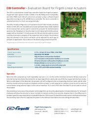
L12 Series Datasheet - Firgelli Technologies
L12 Series Datasheet - Firgelli Technologies
L12 Series Datasheet - Firgelli Technologies

Create successful ePaper yourself
Turn your PDF publications into a flip-book with our unique Google optimized e-Paper software.
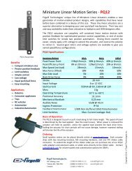
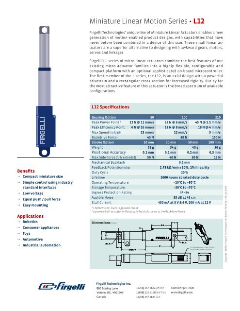
Miniature Linear Motion <strong>Series</strong> • <strong>L12</strong><br />
<strong>Firgelli</strong> <strong>Technologies</strong>’ unique line of Miniature Linear Actuators enables a new<br />
generation of motion-enabled product designs, with capabilities that have<br />
never before been combined in a device of this size. These small linear actuators<br />
are a superior alternative to designing with awkward gears, motors,<br />
servos and linkages.<br />
<strong>Firgelli</strong>’s L series of micro linear actuators combine the best features of our<br />
existing micro actuator families into a highly flexible, configurable and<br />
compact platform with an optional sophisticated on-board microcontroller.<br />
The first member of the L series, the <strong>L12</strong>, is an axial design with a powerful<br />
drivetrain and a rectangular cross section for increased rigidity. But by far<br />
the most attractive feature of this actuator is the broad spectrum of available<br />
configurations.<br />
<strong>L12</strong> Specifications<br />
Benefits<br />
→ Compact miniature size<br />
→ Simple control using industry<br />
standard interfaces<br />
→ Low voltage<br />
→ Equal push / pull force<br />
→ Easy mounting<br />
Applications<br />
→ Robotics<br />
→ Consumer appliances<br />
→ Toys<br />
→ Automotive<br />
→ Industrial automation<br />
Gearing Option 50 100 210<br />
Peak Power Point 1 12 N @ 11 mm/s 23 N @ 6 mm/s 45 N @ 2.5 mm/s<br />
Peak Efficiency Point 6 N @ 16 mm/s 12 N @ 8 mm/s 18 N @ 4 mm/s<br />
Max Speed (no load) 23 mm/s 12 mm/s 5 mm/s<br />
Backdrive Force 2 43 N 80 N 150 N<br />
Stroke Option 10 mm 30 mm 50 mm 100 mm<br />
Weight 28 g 34 g 40 g 56 g<br />
Positional Accuracy 0.1 mm 0.2 mm 0.2 mm 0.3 mm<br />
Max Side Force (fully extended) 50 N 40 N 30 N 15 N<br />
Mechanical Backlash<br />
0.1 mm<br />
Feedback Potentiometer<br />
2.75 kΩ/mm ± 30%, 1% linearity<br />
Duty Cycle 20 %<br />
Lifetime<br />
1000 hours at rated duty cycle<br />
Operating Temperature<br />
–10°C to +50°C<br />
Storage Temperature<br />
–30°C to +70°C<br />
Ingress Protection Rating<br />
IP–54<br />
Audible Noise<br />
55 dB at 45 cm<br />
Stall Current<br />
450 mA at 5 V & 6 V, 200 mA at 12 V<br />
1 1 N (Newton) = 0.225 lb f<br />
(pound-force)<br />
2 a powered-off actuator will statically hold a force up to the Backdrive Force<br />
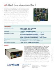
Dimensions (mm)<br />
cm AWG leadwires with . mm<br />
pitch female header connector<br />
Copyright 2008 © <strong>Firgelli</strong> <strong>Technologies</strong> Inc. Patent Pending. • 23 July 2008
<strong>L12</strong> Specifications<br />
Load Curves<br />
Current Curves<br />
<br />
<br />
<br />
Gearing Option<br />
<br />
<br />
<br />
<br />
<br />
6 V Models<br />
Gearing Option<br />
<br />
<br />
<br />
<br />
<br />
Speed (mm/s)<br />
<br />
<br />
<br />
Current (mA)<br />
<br />
<br />
<br />
V Models<br />
Gearing Option<br />
<br />
<br />
<br />
<br />
Force (N)<br />
<br />
Force (N)<br />
Model Selection<br />
The <strong>L12</strong> has five configurable features. <strong>L12</strong> configurations are identified<br />
according to the following scheme:<br />
<strong>L12</strong>-SS-GG-VV-C-L<br />
feature<br />
options<br />
SS: Stroke Length (in mm) 10, 30, 50, 100<br />
Any stroke length between 10 and<br />
100 mm is available on custom orders,<br />
in 2 mm increments.<br />
GG: Gear reduction ratio<br />
(refer to force/speed plots)<br />
50, 100, 210<br />
Other gearing options may be possible on<br />
custom orders.<br />
VV: Voltage<br />
12 12 V<br />
C: Controller B Basic 2-wire open-loop interface,<br />
no position feedback, control, or limit<br />
switching. Positive voltage extends,<br />
negative retracts.<br />
L: Mechanical or electrical<br />
interface customizations<br />
06 6 V<br />
S<br />
P<br />
I<br />
R<br />
2-wire open-loop interface with limit<br />
switching at stroke endpoints.<br />
Simple analog position feedback<br />
signal, no on-board controller.<br />
Integrated controller with Industrial and<br />
RC servo interfaces (see <strong>L12</strong> Controller<br />
Options section). Not available with<br />
10mm stroke length configurations.<br />
RC Linear Servo. Not available with<br />
10mm stroke or 12 volts.<br />
Custom option codes will be issued by<br />
<strong>Firgelli</strong> for custom builds when applicable.<br />
Basis of Operation<br />
The <strong>L12</strong> actuator is designed to move push or pull<br />
loads along its full stroke length. The speed of<br />
travel is determined by the gearing of the actuator<br />
and the load or force the actuator is working<br />
against at a given point in time (see Load Curves<br />
chart on this datasheet). When power is removed,<br />
the actuator stops moving and holds its position,<br />
unless the applied load exceeds the backdrive<br />
force, in which case the actuator will backdrive.<br />
Stalling the actuator under power for short periods<br />
of time (several seconds) will not damage the<br />
actuator. Do not reverse the supply voltage polarity<br />
to actuators containing an integrated controller<br />
(I controller option).<br />
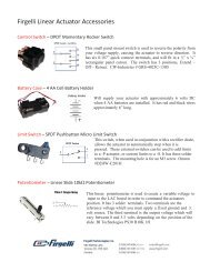
Each <strong>L12</strong> actuator ships with two mounting<br />
clamps, two mounting brackets and two rod end<br />
options: a clevis end and a threaded end with<br />
nut (see drawing on page 4). When changing rod<br />
ends, extend the actuator completely and hold<br />
the round shaft while unscrewing the rod end.<br />
Standard lead wires are 28 AWG, 30 cm long with<br />
2.56 mm (0.1") pitch female header connector (Hi-<br />
Tec and Futaba compatible). Actuators are a<br />
sealed unit (IP–54 rating, resistant to dust and<br />
water ingress but not fully waterproof).<br />
Ordering information<br />
Sample quantities may be ordered with a credit<br />
card directly from www.firgelli.com.<br />
Please contact <strong>Firgelli</strong> at sales@firgelli.com for<br />
volume pricing or custom configurations.<br />
Note that not all configuration combinations<br />
are stocked as standard products. Please refer<br />
to www.firgelli.com/orders for current inventory.<br />
Miniature Linear Motion <strong>Series</strong> • <strong>L12</strong> <strong>Firgelli</strong> <strong>Technologies</strong> Inc. for more info call 1 (888) 225-9198 or visit www.firgelli.com
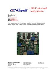
<strong>L12</strong> Controller options<br />
Option S—Basic 2-wire interface<br />
WIRINg:<br />
1 (red) Motor V+ (6 V or 12V)<br />
2 (black) Motor ground<br />
When the actuator moves to a position<br />
within 0.5mm of its fully-retracted or fully-extended<br />
stroke endpoint, a limit switch<br />
will stop power to the motor. When this<br />
occurs, the actuator can only be reversed<br />
away from the stroke endpoint. Once the<br />
actuator is positioned away from it’s stroke<br />
endpoint, normal operation resumes. For<br />
custom orders, limit switch trigger positions<br />
can be modified at the time of manufacture,<br />
in 0.5mm increments.<br />
Option P—Position feedback signal<br />
WIRINg:<br />
5 (yellow) Feedback potentiometer<br />
positive reference rail<br />
Option I—Integrated controller with<br />
industrial and RC servo interfaces<br />
WIRINg:<br />
1 (green) Current input signal (used for<br />
4–20 mA interface mode)<br />
2 (blue) Voltage input signal (used for<br />
the 0–5V interface mode and<br />
PWM interface modes)<br />
3 (purple) Position Feedback signal<br />
(0–3.3 V, linearly proportional<br />
to actuator position)<br />
4 (white) RC input signal (used for RCservo<br />
compatible interface mode)<br />
5 (red) Motor V+ (+6 Vdc for 6 V models,<br />
+12 Vdc for 12 V models)<br />
6 (black) ground<br />
The –I actuator models feature an onboard<br />
software-based digital microcontroller.<br />
The microcontroller is not userprogrammable<br />
The six lead wires are split into two connectors.<br />
Leads 4, 5 and 6 terminate at a<br />
1 (orange) Feedback potentiometer<br />
negative reference rail<br />
universal RC servo three-pin connector<br />
2 (purple) Feedback potentiometer (Hi-Tec and Futaba compatible). Leads Option R—RC Linear Servo<br />
wiper (position signal)<br />
1, 2 and 3 terminate at a separate, similarly<br />
WIRINg:<br />
3 (red) Motor V+ (6 V or 12 V)<br />
sized connector.<br />
4 (black) Motor ground 1 (white) RC input signal<br />
The –P actuators offer no built-in controller,<br />
but do provide an analog position feedback<br />
signal that can be input to an external<br />
controller. While voltage is applied to<br />
the motor V+ and ground leads, the actuator<br />
extends. If the polarity of this voltage<br />
is reversed, the actuator retracts. Actuator<br />
stroke position may be monitored by providing<br />
any stable low and high reference<br />
voltages on leads 1 and 5, and then reading<br />
the position signal on lead 2. The voltage<br />
on lead 2 will vary linearly between<br />
the two reference voltages in proportion<br />
to the position of the actuator stroke.<br />
When the actuator is powered up, it will<br />
repeatedly scan leads 1, 2, 4 for an input<br />
signal that is valid under any of the four<br />
supported interface modes. When a valid<br />
signal is detected, the actuator will selfconfigure<br />
to the corresponding interface<br />
mode, and all other interface modes and<br />
input leads are disabled until the actuator<br />
is next powered on.<br />
0–5 V Interface Mode: This mode allows<br />
the actuator to be controlled with just a<br />
battery, and a potentiometer to signal the<br />
desired position to the actuator – a simple<br />
interface for prototypes or home automation<br />
projects. The desired actuator position<br />
(setpoint) is input to the actuator on<br />
lead 2 as a voltage between ground and<br />
5 V. The setpoint voltage must be held on<br />
lead 2 until the desired actuator stroke position<br />
is reached. Lead 2 is a high impedance<br />
input.<br />
4–20 mA Interface Mode: This mode is<br />
compatible with PLC devices typically<br />
used in industrial control applications.<br />
The desired actuator position (setpoint) is<br />
input to the actuator on lead 1 as a current<br />
between 4 mA and 20 mA. The setpoint current<br />
must be held on lead 1 until the desired<br />
actuator stroke position is reached.<br />
RC Servo Interface Mode: This is a standard<br />
hobby-type remote-control digital servo<br />
interface (CMOS logic), compatible with<br />
servos and receivers from manufacturers<br />
like Futaba and Hi-Tec. The desired actuator<br />
position is input to the actuator on<br />
lead 4 as a positive 5 Volt pulse width signal.<br />
A 1.0 ms pulse commands the controller to<br />
fully retract the actuator, and a 2.0 ms pulse<br />
signals full extension. If the motion of the<br />
actuator, or of other servos in your system,<br />
seems erratic, place a 1–4Ω resistor in series<br />
with the actuator’s red V+ leadwire.<br />
PWM Mode: This mode allows control of<br />
the actuator using a single digital output<br />
pin from an external microcontroller. The<br />
desired actuator position is encoded as<br />
the duty cycle of a 5 Volt 1 kHz square wave<br />
on actuator lead 2, where the % duty cycle<br />
sets the actuator position to the same %<br />
of full stroke extension. The waveform<br />
must be 0V to +5V in order to access the<br />
full stroke range of the actuator.<br />
2 (red) Motor V+ (6 VDC)<br />
3 (black) ground<br />
The –R actuators or ‘linear servos’ are<br />
a direct replacement for regular radio<br />
controlled hobby servos. Operation is as<br />
above in RC servo interface mode (option<br />
I). The –R actuators are available in 6 volt<br />
and 30, 50 and 100 mm strokes only.<br />
Miniature Linear Motion <strong>Series</strong> • <strong>L12</strong> <strong>Firgelli</strong> <strong>Technologies</strong> Inc. for more info call 1 (888) 225-9198 or visit www.firgelli.com
Miniature Linear Motion <strong>Series</strong> • <strong>L12</strong> <strong>Firgelli</strong> <strong>Technologies</strong> Inc. for more info call 1 (888) 225-9198 or visit www.firgelli.com