01. New Symbols - 2009 Standard - Technical Training Consultants
01. New Symbols - 2009 Standard - Technical Training Consultants
01. New Symbols - 2009 Standard - Technical Training Consultants

You also want an ePaper? Increase the reach of your titles
YUMPU automatically turns print PDFs into web optimized ePapers that Google loves.
856 SALT LAKE COURT SAN JOSE, CA 95133 (408) 251–5329<br />
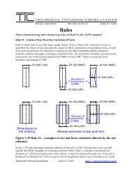
<strong>New</strong> <strong>Symbols</strong><br />
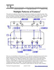
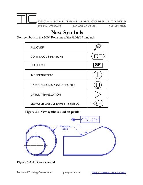
<strong>New</strong> symbols in the <strong>2009</strong> Revision of the GD&T <strong>Standard</strong> 1<br />
ALL OVER<br />
CONTINUOUS FEATURE<br />
SPOT FACE<br />
INDEPENDENCY<br />
UNEQUALLY DISPOSED PROFILE<br />
CF<br />
SF<br />
I<br />
U<br />
DATUM TRANSLATION<br />
MOVABLE DATUM TARGET SYMBOL<br />
A1<br />
Figure 3-1 <strong>New</strong> symbols used on prints<br />
Tolerance<br />
Zone<br />
Figure 3-2 All Over symbol<br />
<strong>Technical</strong> <strong>Training</strong> <strong>Consultants</strong> (408) 251-5329 http://www.ttc-cogorno.com
The All over symbol, used with the profile control, consists of two small concentric circles<br />
placed at the joint of the leader connecting the feature control frame to the feature. Where the all<br />
over symbol is specified, the profile applies all over the three-dimensional surface of the part as<br />
shown in Fig. 3-2.<br />
Ø1.00-1.02<br />
CF<br />
Figure 3-3 Continuous feature symbol<br />
The Continuous feature symbol specifies that a group of two or more interrupted features of size<br />
are to be considered one single feature of size shown in Figure 3-3.<br />
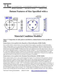
Ø.750<br />
$Ø1.000^.625<br />
Depth Symbol<br />
Counterbore Symbol<br />
Ø.500<br />
%Ø.875 X 82°<br />
Countersink Symbol<br />
Ø.280<br />
SF Ø.630<br />
Spotface Symbol<br />
Figure 3-4 Spotface symbol<br />
Where a Spotface is indicated, either the depth or the remaining thickness of the material may be<br />
specified. If no depth or remaining thickness is specified, the spotface is the minimum depth<br />
necessary to clean up the surface of the specified diameter.<br />
<strong>Technical</strong> <strong>Training</strong> <strong>Consultants</strong> (408) 251-5329 http://www.ttc-cogorno.com
Ø.500-.505<br />
I<br />
Figure 3-5 Independency Symbol<br />
The Independency symbol, circle I, indicates that perfect form of a feature of size at MMC or<br />
LMC is not required. However, a supplementary form tolerance(s) may be required to limit<br />
excessive variations of form as shown in Fig. 3-5.<br />
Figure 3-6 Unequally disposed profile symbol<br />
The Unequally Disposed Profile symbol, circle U, indicates a unilateral tolerance or a tolerance<br />
unequally disposed about the true profile. This symbol shall be placed in the feature control<br />
frame following the tolerance value as shown in Fig. 3-6. The tolerance that would allow<br />
additional material added to the true profile is place after the circle U.<br />
1 Cogorno, Gene R., Geometric Dimensioning and Tolerancing for Mechanical Design, Second<br />
Edition, McGraw-Hill, <strong>New</strong> York, 2011, pp. 24 and 117.<br />
<strong>Technical</strong> <strong>Training</strong> <strong>Consultants</strong> (408) 251-5329 http://www.ttc-cogorno.com
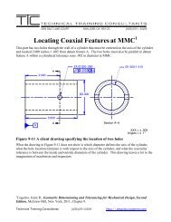
A1<br />
B1<br />
2.125<br />
6.000<br />
C1<br />
45°<br />
.750<br />
45°<br />
.750<br />
B2<br />
Ø 2.000<br />
A2<br />
2X Ø.260-.280<br />
A3<br />
C2<br />
B1<br />
B2<br />
.250<br />
.500<br />
C1<br />
C2<br />
A<br />
1.000<br />
A1<br />
A2<br />
A3<br />
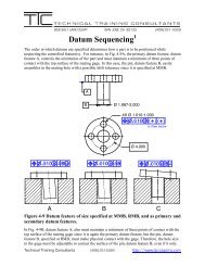
Figure 4-8 Movable Datum targets equalizing datum features<br />
The Movable Datum Target symbol indicates that a datum target is not fixed at its basic<br />
location and is free to translate.<br />
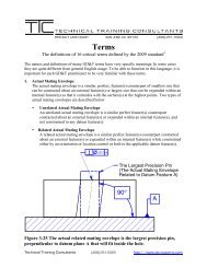
Datum Translation<br />
Symbol<br />
n]w.005]A]B]C ]<br />
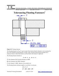
Figure 3-7 Datum Translation symbol<br />
The Datum Translation symbol indicates that a datum feature simulator is not fixed and is free<br />
to translate within the specified geometric tolerance to fully engage the feature.<br />
The maximum material boundary of a datum feature applies at its virtual condition with respect<br />
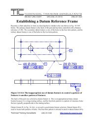
to the previous datum feature. In the drawing on the next page, datum feature D is specified with<br />
a datum translation symbol. The datum translation symbol allows datum feature D to translate<br />
with respect to datum feature B. Consequently, datum feature B is no longer part of the location<br />
equation; the maximum material boundary of datum feature D is 1.005, which is the virtual<br />
condition of datum feature D with respect to datum feature A. The gage, shown below, must first<br />
mate with datum feature A and then with datum feature B. But the translation symbol allows<br />
datum feature D to translate back and forth with respect to datum feature B. In this case, datum<br />
feature simulator D is not located to datum feature simulator B. Datum feature simulator D is a<br />
slot whose width is produced 1.005 wide, the virtual condition of datum feature D with respect to<br />
datum feature A. Datum feature simulator D controls clocking about datum feature B.<br />
<strong>Technical</strong> <strong>Training</strong> <strong>Consultants</strong> (408) 251-5329 http://www.ttc-cogorno.com
.505-.510<br />
C<br />
5.000<br />
.005 M A B M<br />
Ø.995-1.000<br />
D<br />
.010 M A B M C M<br />
.005 M A<br />
Ø1.000-1.010<br />
.005 M A<br />
Ø.495-.500<br />
n]w.005m]A]Bm]Dm ]<br />
.002<br />
B<br />
5.000<br />
Part<br />
A<br />
1.005<br />
Slot<br />
Ø.490<br />
Ø.995<br />
Gage-Makers' Tolerance<br />
Gage<br />
<strong>Technical</strong> <strong>Training</strong> <strong>Consultants</strong> (408) 251-5329 http://www.ttc-cogorno.com