Rehabilitation of old masonry dams at full reservoir level - Talsperren
Rehabilitation of old masonry dams at full reservoir level - Talsperren
Rehabilitation of old masonry dams at full reservoir level - Talsperren

You also want an ePaper? Increase the reach of your titles
YUMPU automatically turns print PDFs into web optimized ePapers that Google loves.
Bettzieche, Heitefuss, Page 1<br />
BRITISH DAM SOCIETY CONFERENCE - 2002<br />
TRINITY COLLEGE DUBLIN<br />
Reservoirs in a changing world<br />
<strong>Rehabilit<strong>at</strong>ion</strong> <strong>of</strong> <strong>old</strong> <strong>masonry</strong> <strong>dams</strong> <strong>at</strong> <strong>full</strong> <strong>reservoir</strong> <strong>level</strong> -<br />
A comparison <strong>of</strong> successful rehabilit<strong>at</strong>ion projects<br />
V BETTZIECHE, Ruhr River Associ<strong>at</strong>ion, GE<br />
C HEITEFUSS, Ruhr River Associ<strong>at</strong>ion, GE<br />
SYNOPSIS. At the beginning <strong>of</strong> the last century about 40 gravity <strong>dams</strong> were<br />
built in Germany. During the last years extensive rehabilit<strong>at</strong>ion measures were<br />
carried out <strong>at</strong> several <strong>old</strong> <strong>masonry</strong> <strong>dams</strong>. <strong>Rehabilit<strong>at</strong>ion</strong> concepts which called<br />
for the construction <strong>of</strong> inspection/drainage galleries inside the <strong>dams</strong> turned out<br />
to be r<strong>at</strong>her cost-efficient. Different methods for the construction <strong>of</strong> these<br />
inspection galleries were used – from manual driving <strong>of</strong> the tunnel to the drill<br />
& blast method and the use <strong>of</strong> a tunnel boring machine. The specific costs <strong>of</strong><br />
these galleries varied, depending on the construction method.<br />
INTRODUCTION<br />
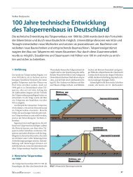
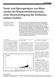
During the first 20 years <strong>of</strong> the last century about 40 gravity <strong>dams</strong> were built<br />
in Germany (Figure 1). These structures were designed as so-called „Intzetype“<br />
<strong>masonry</strong> <strong>dams</strong> with a curved base without any joints.<br />
Figure 1. Masonry Dams in Germany
Bettzieche, Heitefuss, Page 2<br />
Hydraulic structures and <strong>dams</strong> are subject to ageing - like any other<br />
technical structure. The enormous importance <strong>of</strong> a <strong>reservoir</strong> for the<br />
infrastructure <strong>of</strong> the supply area and its damage potential require a<br />
continuing adapt<strong>at</strong>ion to the established technical standards. During the last<br />
years extensive rehabilit<strong>at</strong>ion measures were carried out <strong>at</strong> several <strong>old</strong><br />
<strong>masonry</strong> <strong>dams</strong>.<br />
§©¨¦©<br />
¢¡¤£¦¥¦¥<br />
The specific costs for rehabilit<strong>at</strong>ion varied from 40<br />
metre <strong>of</strong> dam volume.<br />
<strong>Rehabilit<strong>at</strong>ion</strong> concepts which called for the construction <strong>of</strong> inspection<br />
galleries inside the <strong>dams</strong> turned out to be r<strong>at</strong>her cost-efficient. These<br />
galleries serve as means for the inspection <strong>of</strong> the condition <strong>of</strong> the found<strong>at</strong>ion<br />
joints, as well as drainage system for increased w<strong>at</strong>er pressures and for the<br />
install<strong>at</strong>ion <strong>of</strong> monitoring equipment inside the <strong>dams</strong>. Different methods for<br />
the construction <strong>of</strong> these inspection galleries were used – from manual<br />
driving <strong>of</strong> the tunnel to the drill & blast method and the use <strong>of</strong> a tunnel<br />
§©¨<br />
boring machine. The specific costs <strong>of</strong> these galleries varied from 1.100<br />
§©¨<br />
m³ to 2.200 ³ <strong>of</strong> gallery volume, depending on the construction<br />
method.<br />
Three rehabilit<strong>at</strong>ions <strong>at</strong> the Fuerwigge Dam, the Gloer Dam and the Ennepe<br />
Dam are described.<br />
Table 1: Dams d<strong>at</strong>a<br />
Fuerwigge Dam Gloer Dam Ennepe Dam<br />
Year <strong>of</strong> completion 1904 1904 1904/1912<br />
Height <strong>of</strong> Dam [m] 29 32 51<br />
Length <strong>of</strong> Dam [m] 166 168 320<br />
Volume <strong>of</strong> Dam [1000 m³] 26 35 106<br />
Storage Capacity [1000 m³] 1670 2100 12600<br />
THE DAMS<br />
The reason for the construction <strong>of</strong> the Fuerwigge- and Gloer-Dam was the<br />
expansion the activities <strong>of</strong> the steel manufacturing industry in the Sauerland<br />
mountain region during the l<strong>at</strong>e 19 th century and its growing demand for a<br />
sufficient and reliable w<strong>at</strong>er supply for hydro energy purposes. Due to lack<br />
<strong>of</strong> w<strong>at</strong>er, the w<strong>at</strong>er mills and the affili<strong>at</strong>ed manufacturing plants had to be<br />
shut <strong>of</strong>f partly or completely for longer periods every year.<br />
The Fuerwigge- and Gloer-Dam were built between 1904 and 1906 based<br />
upon the design <strong>of</strong> Pr<strong>of</strong>. Intze. With dam heights <strong>of</strong> about 30 m and storage<br />
capacities <strong>of</strong> about 2 hm³ they can be considered as small <strong>reservoir</strong>s.<br />
The Ennepe Dam is a <strong>masonry</strong> dam with a length <strong>of</strong> 320 m and a height <strong>of</strong><br />
51 m and was built between 1902 and 1904 by the former owner, the<br />
Ennepe W<strong>at</strong>er Associ<strong>at</strong>ion. Its main purpose was to stabilise the discharge<br />
<strong>of</strong> the Ennepe River, thus being a reliable source for the gener<strong>at</strong>ion <strong>of</strong>
Bettzieche, Heitefuss, Page 3<br />
hydropower for the factories <strong>at</strong> the lower reaches <strong>of</strong> the river even in periods<br />
<strong>of</strong> drought.<br />
Initially the dam was only 41.4 m high, which resulted in a storage capacity<br />
<strong>of</strong> 10.3 million m³. Between 1910 and 1912 a <strong>masonry</strong> block with a height<br />
10 m was added to the crest <strong>of</strong> the dam. This enabled the former owner to<br />
raise the maximum w<strong>at</strong>er <strong>level</strong> by 2.5 m and cre<strong>at</strong>ed a storage capacity <strong>of</strong><br />
12.6 million m³.<br />
Problems with these <strong>old</strong> <strong>masonry</strong> <strong>dams</strong><br />
Originally these three Dams were not equipped with an inspection- and<br />
drainage gallery. As usual <strong>at</strong> many <strong>old</strong> <strong>masonry</strong> <strong>dams</strong>, a drainage system<br />
consisting <strong>of</strong> vertical stoneware pipes had been installed right behind the<br />
upstream face <strong>of</strong> the <strong>dams</strong>. Unintentionally these drainage pipes had been<br />
filled with grouting m<strong>at</strong>erial during several repair works in the1950 th . Thus<br />
during the last decades there was no effective drainage system available<br />
both in the <strong>dams</strong> and in their bedrock.<br />
These <strong>old</strong> <strong>masonry</strong> <strong>dams</strong> were designed without taking the pore pressure<br />
respectively the uplift into account, based on the basic design principles<br />
Pr<strong>of</strong>. Intze applied <strong>at</strong> the early <strong>masonry</strong> <strong>dams</strong>. Therefore the entire structure<br />
proved to be r<strong>at</strong>her slender. At the beginning <strong>of</strong> the 1980´s this problem was<br />
detected by the Reservoir Supervision Authority. According to the current<br />
view <strong>of</strong> the physical effects <strong>of</strong> the uplift phenomenon the authorities<br />
demanded the immedi<strong>at</strong>e adapt<strong>at</strong>ion <strong>of</strong> the Dams to the established technical<br />
standards. The maximum storage <strong>level</strong> had to be reduced for safety reasons<br />
<strong>at</strong> many <strong>old</strong> <strong>dams</strong> in Germany,<br />
For different reasons the required adapt<strong>at</strong>ion some <strong>dams</strong> was not carried out<br />
until the 1990 th . In June 1997 the Ruhr River Associ<strong>at</strong>ion took over the<br />
Ennepe Dam from the former owner, the Ennepe W<strong>at</strong>er Associ<strong>at</strong>ion under<br />
the oblig<strong>at</strong>ion to adapt the dam to the established technical standards and to<br />
carry out rehabilit<strong>at</strong>ion measures for the long term safety <strong>of</strong> the structure.<br />
The Fuerwigge Dam is owned by the Ruhr River Associ<strong>at</strong>ion since 1933. Its<br />
refurbishment was postponed for the time being. The same goes for the<br />
Gloer-Dam, which is currently refurbished by the Ruhr River Associ<strong>at</strong>ion<br />
on behalf <strong>of</strong> the owner, the City <strong>of</strong> Luedenscheid municipal w<strong>at</strong>er works.<br />
Specially the Ennepe Dam - as mentioned above - was built for the w<strong>at</strong>er<br />
supply <strong>of</strong> 170.000 consumers in the Ennepe-Ruhr District. Therefore during<br />
the rehabilit<strong>at</strong>ion process the <strong>reservoir</strong> could not be emptied without causing<br />
major problems. Former investig<strong>at</strong>ions show th<strong>at</strong> a temporary conversion <strong>of</strong><br />
the w<strong>at</strong>er supply system to other sources would cost about 13 million US-$<br />
and had only a slight chance for realis<strong>at</strong>ion therefore. The basic principles<br />
for the adapt<strong>at</strong>ion <strong>of</strong> the dam to the established technical rules had to take<br />
this into account.
Bettzieche, Heitefuss, Page 4<br />
Different concepts were worked out, to adapt the dam to the established<br />
technical standards. As <strong>at</strong> many other <strong>old</strong> <strong>masonry</strong> <strong>dams</strong> in the<br />
neighbourhood the first idea was to build a concrete diaphragm wall <strong>at</strong> the<br />
upstream side <strong>of</strong> the Ennepe dam. First calcul<strong>at</strong>ions showed th<strong>at</strong> this would<br />
take about 40 Mio. <br />
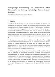
REHABILITATION CONCEPT "DRAINING THE DAM"<br />
A concept for the rehabilit<strong>at</strong>ion <strong>of</strong> <strong>dams</strong> has been developed further by the<br />
Ruhr River Associ<strong>at</strong>ion, being used first time in 1965 <strong>at</strong> the rebuilding <strong>of</strong><br />
the Lister Dam: to stabilise the entire structure by reducing the uplift.<br />
The most important elements <strong>of</strong> this concept were:<br />
• the construction <strong>of</strong> a drainage gallery close to the upstream face <strong>at</strong><br />
normal <strong>reservoir</strong> <strong>level</strong> and<br />
• to drain <strong>masonry</strong> and bedrock with fans <strong>of</strong> drainage borings.<br />
Additional rehabilit<strong>at</strong>ion measures were carried out <strong>at</strong> all <strong>reservoir</strong>s e.g.:<br />
• the replacement <strong>of</strong> the intake g<strong>at</strong>es and conduits<br />
• the rehabilit<strong>at</strong>ion <strong>of</strong> the g<strong>at</strong>e towers<br />
• a new layout for the w<strong>at</strong>er supply intakes.<br />
This concept was developed so far, th<strong>at</strong> there was no doubt about the<br />
feasibility and then submitted to the district authorities for permission and<br />
funding.<br />
Figure 2. Realised concept <strong>of</strong> rehabilit<strong>at</strong>ion <strong>of</strong> the Ennepe Dam, using<br />
draining<br />
The Reservoir Supervision Authority agreed upon the entire rehabilit<strong>at</strong>ion<br />
concept, under the reserv<strong>at</strong>ion, th<strong>at</strong> measurements had to prove the success<br />
<strong>of</strong> the rehabilit<strong>at</strong>ion.
Bettzieche, Heitefuss, Page 5<br />
FEM-Model<br />
The rehabilit<strong>at</strong>ion concept was based upon a detailed feasibility study,<br />
applying different numerical simul<strong>at</strong>ion methods. On the basis <strong>of</strong> these<br />
simul<strong>at</strong>ions the Reservoir Supervision Authority agreed in the concepts <strong>of</strong><br />
rehabilit<strong>at</strong>ion.<br />
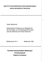
Three numerical models, using the Finite-Element-Method (FEM) were<br />
used:<br />
• a fluid-FEM-model to analyse the seepage inside the dam and the effect<br />
<strong>of</strong> the internal w<strong>at</strong>erforces (porepresure)<br />
• a FEM-model <strong>of</strong> temper<strong>at</strong>ureflow for the quantific<strong>at</strong>ion <strong>of</strong> the influence<br />
<strong>of</strong> the seasonal temper<strong>at</strong>ures and from this resulting the internal stresses<br />
in the dam (Bettzieche, V. 2000b)<br />
• a FEM-model <strong>of</strong> crack propag<strong>at</strong>ion to prove the stability and the<br />
occurrence <strong>of</strong> cracks, essentially affected by the stresses, determined by<br />
the first two models (Bettzieche, V. 2000a)<br />
Figure 3: FEM-calcul<strong>at</strong>ed field <strong>of</strong> porepressure<br />
The layout scheme <strong>of</strong> the drainage borings, as one <strong>of</strong> the most important<br />
assumptions, had to be checked. The numerical calcul<strong>at</strong>ions led to a<br />
provisional distance <strong>of</strong> 4 m between the drainage fans <strong>at</strong> the Ennepe Dam<br />
and 3 m <strong>at</strong> the Glör Dam. It had to be examined, if this distance was
Bettzieche, Heitefuss, Page 6<br />
sufficient for a reliable reduction <strong>of</strong> the uplift pressure inside and<br />
underne<strong>at</strong>h the dam.<br />
Table 2: D<strong>at</strong>a <strong>of</strong> the <strong>Rehabilit<strong>at</strong>ion</strong><br />
Fürwigge Dam Glör Dam Ennepe Dam<br />
(Concept)<br />
<strong>Rehabilit<strong>at</strong>ion</strong> Concept only borings blasting a<br />
tunnel<br />
tunnel boring<br />
machine<br />
Length <strong>of</strong> the Gallery 0 m 45 m 430 m<br />
Pr<strong>of</strong>ile <strong>of</strong> the Gallery no gallery 2,20 m x 3,00 m ∅ 3,00 m<br />
Total Length <strong>of</strong> Drainage 900 m 580 m 1350 m<br />
borings<br />
Costs <strong>of</strong> Drainage<br />
- 330.000 4.000.000<br />
Gallery<br />
Costs <strong>of</strong> Borings 205.000 150.000 250.000<br />
Costs <strong>of</strong> Injections 95.000 65.000 -<br />
The investig<strong>at</strong>ions <strong>at</strong> the Fuerwigge Dam indic<strong>at</strong>e th<strong>at</strong> a drainage gallery is<br />
not necessary. The rehabilit<strong>at</strong>ion concept calls for the install<strong>at</strong>ion <strong>of</strong> a fan <strong>of</strong><br />
drainage borings only. These borings can be driven from the bottom outlet<br />
galleries, which cross the dam (s. Figure 4).<br />
Figure 4. Drain Borings inside the Fürwigge Dam (Scheme)<br />
Measurements<br />
It has been mentioned, th<strong>at</strong> before the execution <strong>of</strong> final stability<br />
calcul<strong>at</strong>ions the effects <strong>of</strong> the drainage measures on the pressure conditions<br />
inside the dam and the bedrock had to be investig<strong>at</strong>ed by experimental<br />
measurings (Bettzieche, V. & Heitefuss, C. 2001).<br />
At the Ennepe Dam i.e. the following measuring devices have been<br />
installed, according to the German Guidelines (ATV/DVWK 1991):<br />
• 2 plumblines, l = 50 m (from the crest to the gallery),<br />
• 2 invert plumblines, l = 25 m (in continu<strong>at</strong>ion to the plumblines),
Bettzieche, Heitefuss, Page 7<br />
• 2 inclinometers for monitoring <strong>of</strong> possible movements <strong>of</strong> the crest<br />
• 2 measuring sections with 9 piezometers each, in order to monitor the<br />
piezometric pressures from the upstream to the downstream face <strong>of</strong> the<br />
dam.<br />
• 2 measuring sections with 40 temper<strong>at</strong>ure gauges together and an<br />
additional fibreoptical sensor (Bettzieche, V. 1997b).<br />
Since the Ennepe Dam was supposed to be run without a steady oper<strong>at</strong>ing<br />
crew, all relevant d<strong>at</strong>a <strong>of</strong> the structure are provided for external monitoring<br />
via a d<strong>at</strong>a transmission system.<br />
REHABILITATION<br />
General solutions for the rehabilit<strong>at</strong>ion <strong>of</strong> <strong>dams</strong> do not exist, but a wide<br />
variety <strong>of</strong> technical concepts. The choice <strong>of</strong> a rehabilit<strong>at</strong>ion concept requires<br />
the adapt<strong>at</strong>ion <strong>of</strong> the optimal technical and economical solution to the<br />
specific hydraulic structure.<br />
During the last years some gravity <strong>dams</strong> were refurbished by the install<strong>at</strong>ion<br />
<strong>of</strong> an concrete diaphragm wall <strong>at</strong> the upstream face. This requires the<br />
complete drawdown <strong>of</strong> the <strong>reservoir</strong>, allowing a restricted w<strong>at</strong>er supply <strong>at</strong><br />
the most. Additionally the sealing <strong>of</strong> the bedrock is necessary in order to<br />
prevent uplift pressures.<br />
In many cases <strong>dams</strong> have been refurbished by a combin<strong>at</strong>ion <strong>of</strong> grouting<br />
and drainage measures. For this purpose cement is injected through<br />
boreholes into the dam and the bedrock, reducing the permeability to a<br />
tolerable <strong>level</strong>. The sealing <strong>of</strong> the dam and the drainage <strong>of</strong> the bedrock<br />
reduces the uplift pressure. The drainage borings collect the seepage w<strong>at</strong>er<br />
in order to guarantee the prevention <strong>of</strong> excessive uplift pressures.<br />
The construction <strong>of</strong> the boreholes requires the driving <strong>of</strong> a drainage- and<br />
inspection gallery <strong>at</strong> the upstream foot <strong>of</strong> the dam. These galleries with a<br />
width <strong>of</strong> 2 to 3 m and a height <strong>of</strong> about 2.5 m run through the dam<br />
longitudinally in the found<strong>at</strong>ion joint.<br />
These inspection galleries have been driven with various methods, for<br />
instance the manual driving, the use <strong>of</strong> a tunnel boring machine and the drill<br />
& blast-method.<br />
Manual Driving <strong>of</strong> the Gallery<br />
For the construction <strong>of</strong> the inspection gallery <strong>at</strong> the Unteren<br />
Herbringhaeuser Dam near the City <strong>of</strong> Wuppertal the manual driving was<br />
chosen (Aberle, B. & Hellmann, H. 2000). This method can be adapted to<br />
the local conditions very good. The precise contours and varying courses <strong>of</strong><br />
the gallery can easily be driven. Masonry made <strong>of</strong> greywacke or m<strong>at</strong>erial <strong>of</strong><br />
similar strength allow only very limited r<strong>at</strong>es <strong>of</strong> advance - <strong>of</strong>ten less than<br />
0.1 m per work shift. The excav<strong>at</strong>ion <strong>of</strong> the <strong>masonry</strong> can be supported by<br />
cracking equipment and hydraulic jacks, even though the use <strong>of</strong> machinery<br />
is limited by the small cross sections <strong>of</strong> the galleries. The irrit<strong>at</strong>ion by dust
Bettzieche, Heitefuss, Page 8<br />
and noise in the narrow galleries in combin<strong>at</strong>ion with the heavy work during<br />
many months puts an enormous strain on the tunneling workers.<br />
The strain on the tunneling crews can be reduced by the use <strong>of</strong> overlapping<br />
core drills. Due to the very limited r<strong>at</strong>es <strong>of</strong> advance this method can be<br />
economically used only in very specific situ<strong>at</strong>ions or <strong>at</strong> very short tunneling<br />
stretches like break-throughs.<br />
The Drill & Blast - Method<br />
The drill & blast - method has success<strong>full</strong>y been used by the Ruhr River<br />
Associ<strong>at</strong>ion in the 1970´s for the driving <strong>of</strong> a longitudinal inspection gallery<br />
<strong>at</strong> <strong>full</strong> <strong>reservoir</strong> <strong>level</strong> <strong>at</strong> the Moehne Dam. During the last years inspection<br />
galleries were driven into several <strong>dams</strong> using the drill & blast-method. All<br />
projects showed, th<strong>at</strong> this method can be adapted to every necessary<br />
geometry on site (Aberle, B. & Hellmann, H. 2000). Very steep slopes <strong>at</strong> the<br />
abutments, right-angled junctions and even shafts can be driven precisely.<br />
The very small distance <strong>of</strong> the inspection gallery to the upstream foot <strong>of</strong> the<br />
dam requires a very careful and rock-protecting blasting method. By<br />
protective blasting the vibr<strong>at</strong>ion load and the weakening <strong>of</strong> the surrounding<br />
<strong>masonry</strong> can be limited.<br />
Due to precise blasting these inspection galleries could be constructed<br />
economically with little additional work due to over- or underbreak. Almost<br />
every inspection gallery was constructed without final shotcrete or concrete<br />
linings.<br />
Figure 5. 3-D-CAD-View: Drainage gallery inside <strong>of</strong> the Glör Dam
Bettzieche, Heitefuss, Page 9<br />
Figure 6. Blasting scheme <strong>of</strong> the drainage gallery <strong>of</strong> the Glör Dam<br />
Use <strong>of</strong> a Tunnel Boring Machine<br />
At the Ennepe Dam the Ruhr River Associ<strong>at</strong>ion suggested the construction<br />
<strong>of</strong> the drainage gallery with a tunnel boring machine (TBM). This<br />
construction method was accepted by the Reservoir Supervision Authority.<br />
Even though there was no specific experience with the use <strong>of</strong> a TBM under<br />
these conditions, there seemed to be big advantages concerning the quality<br />
<strong>of</strong> the tunnel. The lack <strong>of</strong> structural disturbance <strong>of</strong> the bedrock and the<br />
<strong>masonry</strong> surrounding the tunnel opening would make any kind <strong>of</strong> lining<br />
unnecessary, turning the gallery into a large scale drainage boring<br />
(Heitefuss, C. & Rissler, P. 1999).<br />
Figure 7: Tunnel boring machine
Bettzieche, Heitefuss, Page 10<br />
In the beginning there seemed to be some problems associ<strong>at</strong>ed with the use<br />
<strong>of</strong> a tunnel boring machine,<br />
• the curved axis <strong>of</strong> the gallery with a radius <strong>of</strong> 150 m,<br />
• the very steep curve <strong>of</strong> the gallery <strong>at</strong> the abutments,<br />
• the length <strong>of</strong> the gallery <strong>of</strong> only 370 m, being unfavourable for the<br />
economical use <strong>of</strong> a TBM<br />
This demanded the use <strong>of</strong> a small and manoeuvrable tunnel boring machine<br />
like the Robbins 81-113-2 TBM by the Murer AG from Switzerland. This<br />
TBM is equipped with only one pair <strong>of</strong> grippers. Therefore this TBM is<br />
compar<strong>at</strong>ively manoeuvrable.<br />
The TBM started on the 24. October 1997 and reached the left end <strong>of</strong> the<br />
gallery on May 14, 1998. Seven weeks l<strong>at</strong>er, on August 18, 1998 the TBM<br />
appeared <strong>at</strong> the target shaft <strong>at</strong> the right abutment. The average r<strong>at</strong>e <strong>of</strong><br />
advance had been 6.7 m per day, the peak performance was 20 m per day.<br />
It can be st<strong>at</strong>ed th<strong>at</strong> the TBM has driven a mostly smooth and circular<br />
gallery 90-95 % <strong>of</strong> the gallery can remain unlined with no additional<br />
support. In the bottom reach, the upper half <strong>of</strong> the gallery runs through the<br />
<strong>masonry</strong> <strong>of</strong> the dam. Since this part is virtually unlined, the visitor has a<br />
remarkable view into the interior <strong>of</strong> the <strong>masonry</strong>, which is almost 100 years<br />
<strong>old</strong>.<br />
PROOF OF THE SUCCESSFUL REHABILITATION<br />
Additionally to the measurements <strong>of</strong> the described measuring instruments<br />
the seepage was measured, which flowed out from each individual drainage<br />
drilling.<br />
A comparison <strong>of</strong> these measurements with the values expected on the basis<br />
the seepage model is possible by averaging the measured outflow <strong>of</strong> the<br />
drillings. The quantities measured <strong>at</strong> the drainage in the <strong>masonry</strong> dam are<br />
clearly below the predictions <strong>of</strong> the model, while the quantity <strong>of</strong> the rock<br />
drainage reaches these. Also the values <strong>of</strong> the surface <strong>of</strong> the gallery are from<br />
same order.<br />
At all <strong>dams</strong> the measured values prove the tightness <strong>of</strong> the <strong>masonry</strong> dam,<br />
which is substantially higher than assumed. The permeability <strong>of</strong> the rock<br />
corresponds to the assumption.<br />
COMPARISON OF THE CONSTRUCTION METHODS<br />
Table 3 compares the described methods. The given values are based on the<br />
evalu<strong>at</strong>ion and on the experiences from the rehabilit<strong>at</strong>ion work <strong>at</strong> a number<br />
<strong>of</strong> <strong>dams</strong>. All given numbers are average values and have to be considered as<br />
a rough estim<strong>at</strong>es.<br />
It can be shown th<strong>at</strong> the r<strong>at</strong>e <strong>of</strong> advance per workshift and the unit price for<br />
the driving <strong>of</strong> one cubic-metre correl<strong>at</strong>e. In case a TBM is used, major<br />
investments and deductions have more importance.
Bettzieche, Heitefuss, Page 11<br />
Table 3. Comparison <strong>of</strong> the construction methods<br />
Method TBM manual*) core<br />
Performance<br />
per worker<br />
and shift<br />
(WS)<br />
blasting<br />
drilling*)<br />
1 m³/ WS 0,4 m³/ WS 0,2 m³/ WS 0,7 m³/ WS<br />
Costs 1.300 ³ <br />
1.800 ³ 2.200<br />
Advantages rapidly, flexible flexible,<br />
less damage minor minor<br />
to the rock expenditure vibr<strong>at</strong>ions<br />
Disadvantanges<br />
only large<br />
diametres<br />
*) s. Aberle, B. & Hellmann, H. 2000<br />
dust and<br />
noise<br />
conditions for<br />
the workers<br />
time<br />
consuming,<br />
expensive<br />
³ 1.100 ³<br />
flexible,<br />
minor<br />
expenditure<br />
accur<strong>at</strong>e<br />
supervision<br />
needed<br />
COSTS AND CONCLUSIONS<br />
The 100 years <strong>old</strong> Fürwigge, Glör and Ennepe dam had to be adapted to the<br />
established technical standards. By numeric simul<strong>at</strong>ions and measurements<br />
as well as new procedures for the propulsion <strong>of</strong> the drainage gallery the<br />
costs <strong>of</strong> rehabilit<strong>at</strong>ion could be reduced. Former solutions, as the use <strong>of</strong> a<br />
diaphragm wall (s. Figure 8) were neglected as r<strong>at</strong>her expensive.<br />
Figure 8. Earlier expensive concept, using a concrete diaphragm wall
#<br />
¨<br />
Bettzieche, Heitefuss, Page 12<br />
At the Ennepe Dam the total costs <strong>of</strong> the rehabilit<strong>at</strong>ion could be bisected <strong>of</strong><br />
%'&¢() *¡¦+'()%,¡-)¡¦¦&./0¨)12¦34<br />
¢¡©¥¡©<br />
40 millions<br />
"!$#<br />
comparison <strong>of</strong> the rehabilit<strong>at</strong>ion <strong>of</strong> the Fürwigge, Glör and Ennepe Dam<br />
with other rehabilit<strong>at</strong>ions based on diaphragm walls, as shown in Table 4.<br />
Table 4. Comparison <strong>of</strong> realised <strong>Rehabilit<strong>at</strong>ion</strong>s (Total Costs)<br />
Dam<br />
Volume<br />
<strong>of</strong> Dam<br />
[1000 m³]<br />
Storage<br />
Capacity<br />
[1000 m³]<br />
Rehabilita<br />
tion<br />
Concept<br />
Costs per<br />
Dam<br />
Volume<br />
Costs per<br />
Storage<br />
Capacity<br />
¥¦¥¦¥<br />
[ 65<br />
m³]<br />
Year <strong>of</strong><br />
complet<strong>at</strong>ion<br />
[ ³]<br />
Fürwigge 1904 26 1670 only 62 0,96<br />
(Concept)<br />
borings<br />
Glör 1904 35 2100 blasting a 63 1,05<br />
tunnel<br />
Ennepe 1904/12 106 12600 tunnel 189 1,59<br />
boring<br />
machine<br />
Dreiläger 1912 85 4280 concrete 177 3,50<br />
Brucher 1913 27 3300 diaphragm<br />
334 2,73<br />
Fuelbecke 1896 17 700<br />
350 8,57<br />
Jubach 1906 27 1050 wall 291 7,62<br />
Hasper 1904 59 2050<br />
304 8,78<br />
REFERENCES<br />
Aberle, B. & Hellmann, H. 2000, Sprengen in Gewichtsstaumauern unter<br />
Vollstau, Proccedings <strong>of</strong> the 12th Bohr- und sprengtechnisches<br />
Kolloquium, Clausthal<br />
Bettzieche, V., et al. 2000a. Simul<strong>at</strong>ion <strong>of</strong> hydr<strong>of</strong>racturing in <strong>masonry</strong> dam<br />
structures. XIII Intern<strong>at</strong>ional Conference on Comput<strong>at</strong>ional Methods in<br />
W<strong>at</strong>er Resources. Calgary<br />
Bettzieche, V. 2000b. Temper<strong>at</strong>ure Measurement in a Masonry Dam by<br />
Means <strong>of</strong> Fibreoptical Sensors. Commission Intern<strong>at</strong>ionale Des Grands<br />
Barrages. Beijing<br />
Bettzieche, V. & Heitefuss, C. 2001. Monitoring as a basis <strong>of</strong> cost-effective<br />
rehabilit<strong>at</strong>ion <strong>of</strong> an <strong>old</strong> <strong>masonry</strong> dam, in: Dams in a European Context,<br />
European ICOLD Symposium, Norway, Swets & Zeitlinger, Lisse, June<br />
2001<br />
German Associ<strong>at</strong>ion for W<strong>at</strong>er Resources und Land Improvement<br />
(ATV/DVWK). 1991. Measuring devices for the check <strong>of</strong> the stability <strong>of</strong><br />
gravity <strong>dams</strong> and embankment <strong>dams</strong>. ATV/DVWK-Merkblätter zur<br />
Wasserwirtschaft (ATV/DVWK-Guidelines). Volume 222<br />
Heitefuss, C. & Rissler, P. 1999. Upgrading <strong>of</strong> the Ennepe dam. Hydropower<br />
& Dams Issue Two. Volume six