BAKER HUGHES
You also want an ePaper? Increase the reach of your titles
YUMPU automatically turns print PDFs into web optimized ePapers that Google loves.
W H AT DOE S I N TEQ M A N U FACTUR E ?<br />
– 5<br />
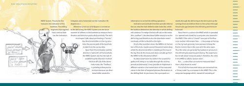
MWD-System. The plumb line<br />
measures the inclination of the<br />
borehole. The drilling<br />
engineers have agreed<br />
that a vertical hole<br />
has the inclination<br />
0 degrees and a horizontal one the inclination 90<br />
degrees etc.).<br />
Whenever a new run of drillpipes is screwed on<br />
to the drill string, the MWD-System uses the short<br />
moment of stillness in the borehole to measure the inclination<br />
and direction particularly precisely. The technical<br />
expert talks about performing a “Survey”.<br />
Our directional driller on the rig calculates<br />
the precise path of the borehole<br />
to date from the survey data.<br />
Apart from the inclination and the<br />
direction (“azimuth”) of the borehole,<br />
the MWD-System also has the task of<br />
establishing the direction in which<br />
the kick-off sub of the downhole<br />
motor, the “Toolface“<br />
is pointing at that precise<br />
moment because our directional<br />
driller needs this<br />
information to control the drilling operation.<br />
Inclination and azimuth therefore provide information<br />
on what the hole drilled to date looks like, whilst<br />
the toolface determines the direction in which drilling<br />
will continue. To realign the kick-off sub on the motor<br />
(the „toolface“), the directional driller simply turns the<br />
drill string (and therefore also the downhole motor)<br />
cautiously a little to the left or the right.<br />
One further question arises: the MWD is at the bottom<br />
of the hole, maybe several thousand meters deep<br />
whilst the directional driller is standing at the top on<br />
the rig. How do the measured values actually go from<br />
the MWD to the directional driller?<br />
As data transmission by cable in the screwed together<br />
drill string or via radio through the rock has<br />
proved problematical, it was possible to implement a<br />
different variation: the transmission of the measured<br />
values in the form of targeted pressure fluctuations in<br />
the drilling fluid. As you know, this is pumped constantly<br />
through the drill string to the bit to pick up the<br />
cuttings there and deliver them to the surface through<br />
the annular gap between the drill string and the borehole<br />
wall.<br />
Now, there is a valve in the MWD which is operated<br />
(i.e. opened and closed) by a computer, also housed in<br />
the MWD. If the valve is “closed” (one part of the flow<br />
cross-section still remains free …), the pumps at the top<br />
on the rig must generate more pressure to keep the<br />
fluid in motion than is the case with the valve open.<br />
Thus the valve can generate fluctuations in pressure in<br />
the drill string by opening and closing. The expert prefers<br />
to talk about “pressure pulses“, therefore, the valve<br />
in the MWD is called a “pulser valve“.<br />
But … a valve that can transmit measured data?<br />
How is that meant to work?<br />
First of all, the measured values are converted into<br />
a “binary code” by a computer in the MWD. This is the<br />
computer language which, instead of consisting of<br />
0<br />
5<br />
10<br />
15<br />
46<br />
47<br />
20


