Design & Analysis of Bellows Free Cryogenic Transfer ... - Nuicone.org
Design & Analysis of Bellows Free Cryogenic Transfer ... - Nuicone.org
Design & Analysis of Bellows Free Cryogenic Transfer ... - Nuicone.org

You also want an ePaper? Increase the reach of your titles
YUMPU automatically turns print PDFs into web optimized ePapers that Google loves.
INSTITUTE OF TECHNOLOGY, NIRMA UNIVERSITY, AHMEDABAD – 382 481, 08-10 DECEMBER, 2011 1<br />
<strong>Design</strong> & <strong>Analysis</strong> <strong>of</strong> <strong>Bellows</strong> <strong>Free</strong> <strong>Cryogenic</strong><br />
<strong>Transfer</strong> Line<br />
A. Amit Thakkar * and B. Mayank I. Vyas<br />
A. M.E. Student, L.D. College <strong>of</strong> Engineering<br />
B. Pr<strong>of</strong>essor, L.D. College <strong>of</strong> Engineering<br />
Abstract--<strong>Cryogenic</strong> transfer line is one <strong>of</strong> the major components<br />
used in any cryogenic system. This transfer line is used to<br />
transport cryogenic liquid from one system to the application at<br />
very low temp. Due to low temp, the cryogenic transfer line tends<br />
to contract. To avoid the thermal stress, bellows are generally<br />
used. But there bellows are not very reliable under the cyclic loads<br />
and they are weak points to have leaks. The reliability is essential<br />
in case <strong>of</strong> space technology and other closed systems which cannot<br />
be opened easily. To make the system reliable, bellows free<br />
transfer line can be designed, which is now very challenging task.<br />
This paper describes the Thermo Structural design & <strong>Analysis</strong> <strong>of</strong><br />
bellow free transfer line.<br />
Index Terms--Ansys, Bellow free, Invar, <strong>Transfer</strong> lines.<br />
C<br />
I. INTRODUCTION<br />
ryogenic transfer line is one <strong>of</strong> the major components<br />
used in any cryogenic system. This transfer line is used to<br />
transport cryogenic liquid from one system to the<br />
application at very low temp. During the flow <strong>of</strong> the cry<strong>of</strong>luid,<br />
the transfer line should be well insulated otherwise<br />
required condition <strong>of</strong> cryo-fluid at the application can’t be<br />
supplied. The insulation to these cryo transfer line is<br />
provided with the help <strong>of</strong> static vacuum. Among static<br />
vacuum insulated transfer lines, there are many different<br />
designs to choose from including flexible pipe, rigid pipe,<br />
internal bellows, external bellows and Invar. The most<br />
reliable transfer line is without bellows; which can be<br />
produced by using the INVAR material. Invar material can<br />
lead to bellow free transfer line. The unique feature <strong>of</strong> a<br />
static vacuum bellow free transfer line is that the<br />
performance over time does not change & there is no<br />
possibility <strong>of</strong> leaking. This type <strong>of</strong> transfer lines are used in<br />
small systems having very high reliability and within the<br />
constrained space for installation.<br />
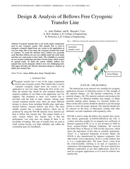
Fig. 1. Difference between the Austenitic line and Invar <strong>Transfer</strong> line [1]<br />
Austenitic<br />
stainless steel<br />
II. INVAR – THE MATERIAL<br />
Invar Piping<br />
The material has to be selected very carefully for cryogenic<br />
applications because <strong>of</strong> following reasons (i) The strength <strong>of</strong><br />
the material changes. (ii) The thermal conductivity <strong>of</strong> the<br />
material changes. (iii) The material contracts and produces the<br />
thermal stress. (iv) Material modulus may change. (v) Many<br />
materials undergo phase changes (i.e. becomes brittle) etc.<br />
Hence all the above points should be checked as per the design<br />
criteria to select the proper material. The material should also<br />
be selected on the basis <strong>of</strong> fabrication, joining with other<br />
materials, cost and compliance with regulatory codes.<br />
INVAR is used to make the bellow free transfer lines. Invar,<br />
also known generically as FeNi36 (64FeNi in the US), is<br />
a nickel steel alloy notable for its uniquely low coefficient <strong>of</strong><br />
thermal expansion (CTE or α). It was invented in 1896 by<br />
Swiss scientist Charles Édouard Guillaume. He received<br />
the Nobel Prize in Physics in 1920 for this discovery, which<br />
shows the importance <strong>of</strong> this alloy in scientific instruments.<br />
"Invar" is a registered trademark <strong>of</strong> Arcelor Mittal, but<br />
FeNi36 is also manufactured by Japanese companies. Like<br />
other nickel / iron compositions, Invar is a solid solution; that<br />
is, it is a single-phase alloy. The name "Invar" comes from<br />
the word invariable, referring to its lack <strong>of</strong> expansion or<br />
contraction with temperature changes. The invar material has<br />
different composition as per their applications. Invar-36 is<br />
used for cryogenic applications so It is used for bellows free<br />
transfer line.
2<br />
INTERNATIONAL CONFERENCE ON CURRENT TRENDS IN TECHNOLOGY, ‘NUiCONE – 2011’<br />
TABLE I<br />
DIFFERENT GRADES OF INVAR MATERIALS<br />
Grade Ni Co Fe<br />
Invar 36 < 0.4 Remainder<br />
Invar-<br />
M93<br />
36 < 0.2 Remainder<br />
Inovar 36 < 0.1 Remainder<br />
Microvar 36 0.25 Remainder<br />
Inovco 33 4.5 Remainder<br />
III. PROBLEM FORMULATION<br />
<strong>Transfer</strong> line is required to cater the liquid from the storage<br />
tank to the point <strong>of</strong> application. Cryo transfer line can be from<br />
few meters to hundreds <strong>of</strong> meter. But bellow free transfer is<br />
generally used in the small length required by the system,<br />
because it is not very economic. But small systems are using<br />
bellow free transfer lines due to its high reliability.<br />
1) Technical specifications required<br />
(After technical discussion with I.P.R. Taken Data)<br />
Type <strong>of</strong> transfer line : Bellow <strong>Free</strong><br />
Operating pressure : 2 bar<br />
Operating temperature : 80 K<br />
Cryo fluid used : LN2<br />
Length <strong>of</strong> the transfer line : 5 m<br />
Number <strong>of</strong> bends : Zero (Only straight transfer line)<br />
Mass flow rate : 2000 litres/hour<br />
Allowable pr. drop per meter : 50 Pa<br />
Insulation : Vacuum & MLI<br />
Configuration : Rigid<br />
Cryo fluid condition : Sub-cooled<br />
Max. allowable deflection : 1 mm<br />
2) Assumptions<br />
A. Single phase liquid i.e. quality <strong>of</strong> the liquid does not<br />
change<br />
B. Configuration <strong>of</strong> line should be completely straight<br />
without any bends<br />
C. Only MLI and vacuum insulated lines are considered.<br />
No other type <strong>of</strong> insulation is considered.<br />
D. Frictional, entry and exit loss is considered only<br />
stresses, generally the bellows are attached with the lines<br />
or sometimes bends have bend given in the straight line.<br />
Different materials are also used at different<br />
temperatures. As we have to design the bellow free<br />
transfer line, so as per the literature survey Invar has to be<br />
used.<br />
Induced thermal stress can be calculated by the following<br />
relation:<br />
σ th = E.*ε th<br />
Where<br />
E = Young’s Modulus<br />
ε th = Thermal strain, this strain can be found as<br />
ε th = α .(t room − t cry<strong>of</strong>luid )<br />
α = Coefficient <strong>of</strong> thermal contraction<br />
t room = Room temperature or atmospheric temp.<br />
t cyr<strong>of</strong>luid = Cryo fluid temp. or temp up to which it is<br />
cooled<br />
The change in the length due to thermal contraction can be<br />
found out by<br />
∆L = ε th .L<br />
Where<br />
L = Original Length <strong>of</strong> the process tube<br />
4) Fluid Properties<br />
Liquid nitrogen is used as the working fluid, which is at<br />
the sub-cooled condition. The fluid properties are taken at 2<br />
bar and 80 K. The following properties are necessary for the<br />
design point <strong>of</strong> view:<br />
Density : 794.11 kg/m3<br />
Viscosity : 1.45E-04 Pa-sec<br />
Velocity <strong>of</strong> sound : 825.95 m/sec<br />
Specific heat (Cp) : 2.05 kJ/kgK<br />
Specific heat (Cv) : 1.06 kJ/kgK<br />
Gamma (Ratio <strong>of</strong> Cp & Cv) : 1.93<br />
3) <strong>Design</strong> Methodology<br />
When any transfer line cool down from room<br />
temperature to the cryo fluid temperature then the<br />
transfer line contracts. If the ends <strong>of</strong> the transfer lines are<br />
fixed then thermal stress are generated in the transfer<br />
line. The ends <strong>of</strong> transfer lines are fixed due to the<br />
stationary systems attached at the ends. The contraction <strong>of</strong><br />
the lines gives the thermal stress to the transfer line.<br />
Thermal stress must be taken care <strong>of</strong> during the<br />
design <strong>of</strong> the transfer line. To overcome the thermal<br />
5) Results<br />
TABLE II<br />
<strong>Design</strong> summary & comparison <strong>of</strong> process lines designed<br />
for INVAR & SS
INSTITUTE OF TECHNOLOGY, NIRMA UNIVERSITY, AHMEDABAD – 382 481, 08-10 DECEMBER, 2011 3<br />
Sr.<br />
No.<br />
Parameter<br />
Name<br />
INVAR<br />
<strong>Transfer</strong><br />
Line<br />
SS <strong>Transfer</strong><br />
Line<br />
1<br />
Contraction <strong>of</strong><br />
the process line<br />
-1.79 mm -14.79 mm<br />
2 Axial Stress 50.12 MPa 588.00 MPa<br />
3<br />
Bellow / U-Loop NOT<br />
requirement REQUIRED<br />
REQUIRED<br />
IV. INPUT DATA FOR ANSYS ANALYSIS<br />
1) Technical Specification required<br />
A. Inner diameter <strong>of</strong> the INVAR line : 45 mm (45 x 10-3 m)<br />
B. Thickness <strong>of</strong> the line: 1.65 mm (1.65 x 10⁻³ m)<br />
C. Outer diameter <strong>of</strong> the INVAR line:48.3mm(48.3x10⁻³ m)<br />
D. Length <strong>of</strong> the INVAR line: 5m<br />
2) <strong>Analysis</strong><br />
A. Mode: Thermo - Structural<br />
B. Type: Static<br />
Fig. 2. Max. Displacement at the free end <strong>of</strong> process line<br />
The maximum displacement at the free end as per above Fig-2.<br />
= -0.001784 m = -1.784 mm<br />
7) Thermal stress due to thermal contraction<br />
For the thermal stress, the other end <strong>of</strong> the process line is<br />
also constrained. The thermal contraction has to be restricted<br />
to get the thermal stress.<br />
3) Element<br />
Solid45 element is used; this element supports the<br />
thermal contraction, temperature and structural properties.<br />
4) Model Statistics<br />
Number <strong>of</strong> volume : 1<br />
Number <strong>of</strong> areas : 6<br />
Number <strong>of</strong> lines : 20<br />
Number <strong>of</strong> key points : 16<br />
Number <strong>of</strong> elements : 16000<br />
Number <strong>of</strong> nodes : 32080<br />
5) Loads<br />
Loads are given as the body loads and defined in terms <strong>of</strong> the<br />
<strong>of</strong> temperature because here temperature is decreasing from<br />
300 K to 80 K.<br />
Reference temperature <strong>of</strong> the process line: 300 K<br />
Uniform temperature <strong>of</strong> the process line: 80 K<br />
Fig. 3. Stress distribution <strong>of</strong> process line<br />
6) Material Properties<br />
Material Number : 1<br />
Material type<br />
: Isotropic<br />
Young’s modulus, EX : 140E+9<br />
Poisson’s ratio, PRXY : 0.3<br />
Thermal Contraction, ALPX : 1.62E-06<br />
Density<br />
: 8118 kg/m3
4<br />
INTERNATIONAL CONFERENCE ON CURRENT TRENDS IN TECHNOLOGY, ‘NUiCONE – 2011’<br />
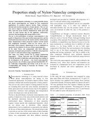
Fig. 4 Stress Vs Length graph <strong>of</strong> process line<br />
The above graph shows that the stress varies from 32.98 MPa<br />
to the 85.50 MPa. But these minimum and maximum stresses<br />
are at the ends only; hence these stresses will not be counted<br />
for the stress finding along the process line. The stress along<br />
the transfer line is between 48.73 MPa and 53.99 MPa. The<br />
exact value can be found out by checking the graph by<br />
magnifying the graph between the length 0.5 to 4.5 m and the<br />
stress value from 50 MPa to 52 MPa.<br />
From range <strong>of</strong> 50 to 52 MPa; Stress value is<br />
between the 50 MPa to 50.20 MPa, which is shown in the Fig<br />
5.<br />
Parameter<br />
Thermal<br />
Analytical<br />
FE<br />
<strong>Analysis</strong><br />
contraction<br />
-1.79mm -1.784mm 1.003<br />
Thermal<br />
stress<br />
50.12Mpa 50.02MPa 1.001<br />
the type <strong>of</strong> transfer lines behaves same but the major difference<br />
in both the transfer line is requirement <strong>of</strong> bellows only.<br />
INVAR transfer lines do not require any bellow while the SS<br />
transfer lines requires bellow or U-loop<br />
VI. REFERENCES<br />
Ratio<br />
(Analytical<br />
/ANSYS)<br />
[1] “Realization <strong>of</strong> Invar Alloy LNG piping” by Takehiko Edamitsu; Osaka<br />
Gas Co., Ltd. Shuji Yamamoto; Osaka Gas Co., Ltd. Muneji Ujita; Osaka Gas<br />
Co., Ltd.; Taketo Yamakawa; Kawasaki Heavy Industries, Ltd.; Setsuji<br />
Kishimoto; Kawasaki Heavy Industries, Ltd. Keiichi Nakamura; Sumitomo<br />
Metal Industries, LTD. Keiichi Yamamoto; Sumitomo Metal Industries.<br />
[2] “Long, <strong>Bellows</strong>-<strong>Free</strong> Vertical Helium <strong>Transfer</strong> Lines for the LHC<br />
<strong>Cryogenic</strong> s ystem” by Gruehagen H. LHC Division, CERN, 1211 Geneva<br />
23, Switzerland, Posselt H & Weber J. LINDE AG, Linde Engineering<br />
Division, D-82049 Hoellriegelskreuth, Germany., Ahlers H. BABCOCK<br />
NOELL NUCLEAR GmbH, site D-46049 Oberhausen, Germany.<br />
[3] “<strong>Cryogenic</strong> Engineering” by R.A. Barron.<br />
[4] ASME Codes for the mechanical design etc.<br />
[5]Technical Discussion with I.P.R BHAT Gandhinagar etc.<br />
[6] Use analysis s<strong>of</strong>tware ANSYS.<br />
Fig. 5 Magnification <strong>of</strong> Stress Vs Length graph <strong>of</strong> process line<br />
8) Results<br />
TABLE III<br />
Comparison <strong>of</strong> result between Analytical design & FE<br />
<strong>Analysis</strong> for INVAR.<br />
V. CONCLUSION<br />
From the above result summary <strong>of</strong> design & analysis for the<br />
cryogenic transfer lines, it can be concluded that the SS<br />
transfer lines can be replaced with INVAR transfer lines. Both