2004 FOX FORX Owner's Manual - Birota
2004 FOX FORX Owner's Manual - Birota
2004 FOX FORX Owner's Manual - Birota

You also want an ePaper? Increase the reach of your titles
YUMPU automatically turns print PDFs into web optimized ePapers that Google loves.
<strong>2004</strong> <strong>FOX</strong> <strong>FORX</strong> Owner’s <strong>Manual</strong><br />
F80RLT - F100RLT - F80X - F100X<br />
TALAS R - TALAS RL - TALAS RLC<br />
FLOAT 80R - FLOAT 80RL - FLOAT 80RLC<br />
FLOAT 100R - FLOAT 100RL - FLOAT100RLC<br />
Vanilla 100R - Vanilla 100RL - Vanilla 100RLC<br />
Vanilla 125R - Vanilla 125RL - Vanilla 125RLC<br />
<strong>FOX</strong> RACING SHOX<br />
130 Hangar Way,<br />
Watsonville, CA 95076<br />
831.274.6500 FAX 831.768.9312<br />
E-Mail: service@foxracingshox.com<br />
Website: www.foxracingshox.com<br />
1
FLOAT Forx Features<br />
One-piece Magnesium Lower Leg<br />
Double butted Aluminum Steerer<br />
Forged Hollow Aluminum Crown<br />
PSC - Precision Steering Control<br />
ILS - Internal Lubrication System<br />
SDC - Shimmed Damping Control<br />
SLT - Scraper Lip Technology<br />
FLOAT Air Spring Technology<br />
TALAS Air Spring Technology<br />
F80 Lightweight Chassis<br />
Vanilla Forx Features<br />
One-piece Magnesium Lower Leg<br />
Double butted Aluminum Steerer<br />
Forged Hollow Aluminum Crown<br />
PSC - Precision Steering Control<br />
ILS - Internal Lubrication System<br />
SDC - Shimmed Damping Control<br />
SLT - Scraper Lip Technology<br />
Vanilla Coil Spring Technology<br />
Adjustable Travel - 80, 100 &125mm<br />
2
Table of Contents<br />
Introduction ................................................................. 4<br />
Contact Information ..................................................... 4<br />
Service / Warranty ....................................................... 4<br />
International Service Centers ....................................... 4<br />
Methods of Payment ................................................... 4<br />
Method of Shipping ..................................................... 4<br />
Warranty Policy ........................................................... 5<br />
Disclaimer ................................................................... 5<br />
Consumer Safety ........................................................ 6<br />
Important Safety Information ........................................ 6<br />
Installation .................................................................. 6<br />
Tire Sizes ................................................................... 7<br />
Brakes ........................................................................ 7<br />
Maintenance ............................................................... 7<br />
Service Intervals .......................................................... 8<br />
Air Pump Instructions ................................................... 8<br />
Bushing Technology and Inspection ............................. 9<br />
Drop-out Thickness Inspection ..................................... 9<br />
General Set-Up Instructions ....................................... 10<br />
Fork Terminology ...................................................... 10<br />
Sag & Spring Tuning<br />
Vanilla Forx ................................................ 10<br />
FLOAT Forx ............................................... 11<br />
TALAS Guidelines ..................................................... 12<br />
Damping Adjustment Guidelines ................................ 13<br />
Changing Travel<br />
FLOAT Forx ............................................... 14<br />
Vanilla Forx ................................................ 15<br />
Changing Oil ............................................................. 17<br />
Seals and Foam Rings .............................................. 22<br />
International Versions<br />
Français .................................................................. 23<br />
Italiano .................................................................. 45<br />
Deutsch .................................................................. 67<br />
Español .................................................................. 89<br />
Japanese .............................................................. 111<br />
3
Introduction<br />
Congratulations on choosing <strong>FOX</strong> <strong>FORX</strong> for your bicycle. In doing so, you have chosen the best suspension fork in the<br />
industry! All <strong>FOX</strong> Racing Shox products are designed, manufactured and assembled by the finest professionals in the<br />
industry. As a consumer and supporter of <strong>FOX</strong> Racing Shox products, you need to be aware of the importance of setting<br />
up your fork correctly to ensure maximum performance. This manual will provide you with the step-by-step instructions of<br />
how to set up your fork. It is a good idea to keep your receipts with this manual and refer to it for service and warranty<br />
issues.<br />
Contact Information<br />
<strong>FOX</strong> Racing Shox<br />
130 Hangar Way<br />
Watsonville, CA 95076<br />
Phone: 831.274.6500<br />
North America: 800.<strong>FOX</strong>.SHOX (369.7469)<br />
Fax: 831.768.9312<br />
Method of Payment<br />
Visa, MasterCard and/or Cashier’s Check<br />
E-mail: service@foxracingshox.com<br />
Website: www.foxracingshox.com<br />
Business Hours: Monday-Friday 8AM-5PM Pacific Time<br />
Method of Shipping<br />
<strong>FOX</strong> Racing Shox uses UPS Ground service within the USA.<br />
Service / Warranty<br />
<strong>FOX</strong> Racing Shox is pleased to offer 48-hour* turnaround for product service, provided the following steps are taken.<br />
1. Contact <strong>FOX</strong> Racing Shox at 800.<strong>FOX</strong>.SHOX to obtain a Return Authorization (R.A.) Number and shipping<br />
address. For International Service Centers, please refer to the list below or contact <strong>FOX</strong> Racing Shox to determine<br />
the Service Center nearest you.<br />
2. Satisfactory proof of purchase receipt is required for warranty consideration.<br />
3. Mark the Return Authorization Number and the Return Address clearly on the outside of the package and send<br />
item to <strong>FOX</strong> Racing Shox or your International Service Center with shipping charges pre-paid by sender.<br />
4. Include a description of the problem, bicycle information (manufacturer, year and model), type of <strong>FOX</strong> product,<br />
spring rate and return address with daytime phone number.<br />
International Service Centers<br />
*International Service Centers operate independently. Service and Warranty turnaround times may vary.<br />
Australia<br />
Dirt Works<br />
011 612-9679-8400<br />
dirtworks@dirtworks.com.au<br />
Germany<br />
Shock Therapy<br />
06126-2267700<br />
support@shock-therapy.com<br />
Philippines<br />
Dan's Bike Shop<br />
011 63 34 435 3633<br />
dansbike@WBI.ph<br />
Belgium<br />
Sabma<br />
011 32 87-631980<br />
sabma@skynet.be<br />
Germany<br />
Toxoholic's<br />
49 6331-258160<br />
toxoholics@t-online.de<br />
Spain<br />
Dirt Racing<br />
011 34-91-663-71-25<br />
mrojo.dirt@nexo.es<br />
Brazil<br />
Plimax 2 Fast<br />
011 5511-251-0633<br />
astec@plimax.com<br />
Israel<br />
DAA Sport Marketing<br />
972-(0)9-865-6960<br />
dan@daa.co.il<br />
Switzerland<br />
<strong>FOX</strong> Racing Shox Europe<br />
011 41-31-809-30-20<br />
frs-europe@bluewin.ch<br />
Canada (West)<br />
Cycle Works<br />
780 440-3200<br />
mail@cycleworks.com<br />
Italy<br />
Pepi Innerhofer<br />
011-39-0473-56-3107<br />
info@pepi.it<br />
Thailand<br />
Uniwave Limited & UWC Co. Ltd.<br />
011 66 2 367 3470<br />
kanate@uniwave.net<br />
Canada (East)<br />
Velocycle, Inc.<br />
514 849 5299<br />
velocycle@primus.ca<br />
Japan<br />
Mom & Pop's<br />
011 81-586-43-6810<br />
mamapapa@mtg.biglobe.ne.jp<br />
The Netherlands<br />
Cannondale Europe BV<br />
011 315 4158 9898<br />
repair@cannondale.com<br />
Czech Republic<br />
Racebike<br />
00420 653 66 12 40<br />
rb@racebike.cz<br />
Korea<br />
Xenon Sports International<br />
011-82-31-555-0077<br />
xenon@netsgo.com<br />
United Kingdom<br />
Mojo Suspension<br />
011 44-1633-615-815<br />
chris@mojo.co.uk<br />
France<br />
FMF Sport Group<br />
011 33-494-541950<br />
fmfsportgroup@wanadoo.fr<br />
New Zealand<br />
Blue Shark Enterprises<br />
011 64-4-589-4535<br />
alastair@mountainbikes.co.nz<br />
United States<br />
<strong>FOX</strong> Racing Shox<br />
831-274-6500<br />
service@foxracingshox.com<br />
4
Warranty Policy<br />
The factory warranty period for your fork is one year (two years in countries in the EU) from the original date of purchase<br />
of the bicycle or fork. A copy of the original purchase receipt must accompany any fork being considered for<br />
warranty service. Warranty is at the full discretion of <strong>FOX</strong> Racing Shox and will cover only defective materials and<br />
workmanship. Warranty duration and laws may vary from state to state and/or country to country.<br />
Parts, components and assemblies subject to normal wear and tear are not covered under this warranty.<br />
<strong>FOX</strong> Racing Shox reserves the right to all final warranty or non-warranty decisions.<br />
General Exclusions from this warranty shall include but are not limited to any failures caused by:<br />
Installation of parts or accessories that are not qualitatively equivalent to genuine <strong>FOX</strong> Racing Shox parts.<br />
Abnormal strain, neglect, abuse and/or misuse.<br />
Accident or collision damage.<br />
Modification of original parts.<br />
Lack of proper maintenance.<br />
Shipping damages or loss (purchase of full value insurance is recommended).<br />
Damage to interior or exterior caused by improper cable routing, rocks, crashes or improper installation.<br />
Oil changes or service not performed by <strong>FOX</strong> Racing Shox or an Authorized Service Center.<br />
Specific Exclusions from this warranty shall include:<br />
Parts replaced due to normal wear and tear and/or routine maintenance.<br />
Parts subject to normal wear and tear and/or routine maintenance:<br />
Bushings<br />
Seals<br />
Suspension fluids<br />
Drop-outs<br />
<strong>FOX</strong> Racing Shox makes no other warranty of any kind, expressed or implied. All implied warranties of merchantability<br />
and fitness for a particular purpose which exceed the obligations and time limits stated in this warranty are hereby<br />
disclaimed by <strong>FOX</strong> Racing Shox and excluded from this warranty.<br />
Warranty Q & A<br />
Q. What costs are my responsibility during the warranty period?<br />
A. The customer is responsible for all costs of maintenance services, non-warranty repairs, accident and collision<br />
damages, oil, seals, bushings and reducers, and mounting hardware.<br />
Q. What are some examples of “abnormal” strain, neglect or abuse?<br />
A. These terms are general and overlap each other in areas. Specific examples are: Hucking, ghost riding, big drop,<br />
stunt / dare-devil riding, riding with broken parts, riding without oil in fork, wrong spring rate, etc.<br />
Q. Does the warranty cover incidental costs such as shipping or transportation?<br />
A. No. The warranty is limited to repair of materials and/or workmanship.<br />
Q. May I perform any or all of the recommended maintenance shown in the owner’s manual?<br />
A. You may perform seal and suspension fluid maintenance as well as bushing and drop-out inspections. If bushings or<br />
drop-outs are worn, they should be replaced by <strong>FOX</strong> Racing Shox or an Authorized Service Center.<br />
Q. May I perform service and repairs on my fork?<br />
A. <strong>FOX</strong> <strong>FORX</strong> are mostly end user serviceable. Oil and travel changes and damper or spring replacement can be<br />
performed by the consumer. To ensure peak performance, extensive repairs and service to the fork should be performed<br />
by a qualified bicycle suspension mechanic, <strong>FOX</strong> Racing Shox or an Authorized Service Center. If in doubt as<br />
to whether or not you are capable of fixing your fork, contact <strong>FOX</strong> Racing Shox or an Authorized Service Center.<br />
Disclaimer<br />
<strong>FOX</strong> Racing Shox is not responsible for any damages to you or others arising from riding, transporting, or other use of<br />
your fork or bicycle. In the event that your fork breaks or malfunctions, <strong>FOX</strong> Racing Shox shall have no liability or<br />
obligation beyond the repair or replacement of your fork pursuant to the terms outlined in the warranty provisions of this<br />
manual.<br />
5
Consumer Safety<br />
RIDING A BICYCLE IS DANGEROUS AND CAN RESULT IN DEATH OR SERIOUS INJURY. TAKE YOUR RESPONSIBILITY TO<br />
YOURSELF AND OTHERS SERIOUSLY.<br />
• Maintain your bicycle and suspension<br />
• Always wear a helmet, protective clothing and eye protection<br />
• Ride within your limits<br />
• Tread lightly<br />
Your bike is equipped with <strong>FOX</strong> Racing Shox suspension. Before riding, take the time to read the <strong>FOX</strong> Racing Shox<br />
manual on setup, use, and service of your fork. If you have questions, call your Authorized <strong>FOX</strong> Racing Shox Service<br />
Center or call <strong>FOX</strong> Racing Shox directly at 831.274.6500.<br />
Important Safety Information<br />
1. Verify that the brakes are installed and adjusted properly before riding the bicycle. Improperly installed or adjusted<br />
brakes can cause loss of control and serious or fatal injuries to the rider. Use only “V” - style or hydraulic cantilever<br />
brakes or disc brakes designed by the manufacturer for use on <strong>FOX</strong> <strong>FORX</strong>. Do not use brace mounted cable leverage<br />
devices. Do not route brake cables or housing through the stem.<br />
2. If your fork loses oil, tops out excessively or makes unusual noises, immediately stop riding and contact <strong>FOX</strong> Racing<br />
Shox or an Authorized <strong>FOX</strong> Racing Shox Service Center for inspection. Unusual noises would be loud and pronounced<br />
clunks and clanks. Some noises such as spring rattle, oil flow and minor clicks are normal.Continued use of the fork<br />
could cause loss of control and serious or fatal injuries.<br />
3. Use only <strong>FOX</strong> Racing Shox replacement parts. Using aftermarket parts on <strong>FOX</strong> <strong>FORX</strong> will void the warranty.<br />
Aftermarket replacement parts could also cause structural failure resulting in loss of control and serious or fatal<br />
injuries.<br />
4. If mounting the bicycle in a carrier designed to hold a fork by its drop-outs, use caution to not tilt the bicycle to either<br />
side. Tilting the bike with the drop-outs in the carrier can cause structural damage to the fork. Ensure that the fork is<br />
fastened securely with the quick release and that the rear wheel is properly held. If the bicycle ever tilts or falls from a<br />
bicycle carrier, do not ride it until it is examined by a qualified dealer, Service Center or <strong>FOX</strong> Racing Shox. A fork leg or<br />
drop-out failure could cause loss of control and serious or fatal injuries.<br />
5. <strong>FOX</strong> <strong>FORX</strong> do not include reflectors for on-road use. <strong>FOX</strong> <strong>FORX</strong> are designed to be used in competitive off-road riding<br />
and racing. Proper reflectors meeting the Consumer Product Safety Commission’s (CPSC) requirements should be installed<br />
if the fork will be used on public roads.<br />
6. <strong>FOX</strong> <strong>FORX</strong> have a crown / steerer / upper tube assembly. These parts are pressed together in a one-time,<br />
precision press-fit operation. Replacement of any of these parts requires a complete new assembly. Do not<br />
attempt to remove or replace the steerer or upper tubes independently of the crown. DO NOT ATTEMPT TO<br />
ADD THREADS TO THREADLESS STEERERS. Modifying the crown / steerer / upper tube assembly as described<br />
here could cause the rider to lose control of the bicycle resulting in serious or fatal injuries.<br />
Installation<br />
Step 1 - Your <strong>FOX</strong> <strong>FORX</strong> should be installed by a qualified bicycle mechanic. Forks installed improperly are dangerous<br />
and can cause loss of control and serious or fatal injuries.<br />
Step 2 - Remove existing fork from the bicycle. Remove the crown race from the fork. Measure the steerer tube length<br />
of the existing fork. Transfer this measurement to the <strong>FOX</strong> <strong>FORX</strong> steerer. Refer to stem manufacturer’s<br />
instructions to be sure there will be enough clamping surface for the stem. If it is necessary to cut the<br />
steerer tube, measure twice and cut once. It is also recommended that a cutting guide be used while cutting<br />
the steerer tube.<br />
Step 3 - Use a crown race setter to install the crown race firmly against the top of the crown. Install the star fangled<br />
nut in the steerer tube. This should be done with a star fangled nut installation tool.<br />
Step 4 - Install the fork on the bicycle. The headset should be adjusted so it turns freely without drag or free play.<br />
Step 5 - Re-install the brakes and adjust the brake pads. Refer to the brake manufacturer’s instructions.<br />
Step 6 - Mount the front wheel being sure that the quick release nuts sit in the fork drop-out counter bores. The quick<br />
release should engage four (4) or more threads. Close the quick release with the lever in front of and<br />
parallel to the left fork leg.<br />
6
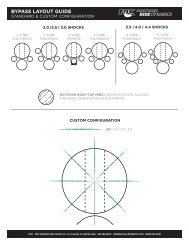
Tire Sizes<br />
<strong>FOX</strong> <strong>FORX</strong> will accept tires sizes up to 2.40 inches wide (e.g. WTB MotoRaptor 55/<br />
60, 26 x 2.40). Any tire larger than 26 x 2.30 must be checked for clearance by the<br />
following method.<br />
Determining Tire Size - With the tire installed and inflated on the rim,<br />
measure the following three dimensions.<br />
Maximum Peak Tire Diameter = 343mm = 27.00 inch<br />
Maximum Edge Tire Diameter = 326mm = 25.67 inch<br />
Maximum Tire Width = 61mm = 2.40 inch<br />
Maximum<br />
Edge Tire<br />
Diameter<br />
Maximum<br />
Peak Tire<br />
Diameter<br />
Do not use a tire if ANY measurement exceeds the maximum dimensions shown above.<br />
Using tires larger than the dimensions shown above is NOT RECOMMENDED and can<br />
cause serious or fatal injury.<br />
Maximum<br />
Tire Width<br />
Brakes<br />
Linear-pull Brakes<br />
Linear-pull brakes (i.e. V-brakes) can be used on <strong>FOX</strong> <strong>FORX</strong>. Use only the <strong>FOX</strong> brake posts supplied with the fork.<br />
Install brake posts and torque to 80 in-lbs. Install and adjust linear-pull brakes according to the manufacturer’s recommendations.<br />
Test brakes for proper operation on flat land. <strong>FOX</strong> <strong>FORX</strong> use a hangerless lower leg design and cannot<br />
use any cantilever style brakes.<br />
Disc Brakes<br />
Disc brakes with 160-180mm rotors can be used on <strong>FOX</strong> <strong>FORX</strong>. Do not use DH rotors larger than 180mm. Install<br />
disc brakes and torque all fasteners according to manufacturer’s recommendations. Install, route and check that all<br />
cables or hydraulic hoses are securely fastened to the lower leg and will not move during compression of the fork. It is<br />
recommended that new disc brake pads be installed to ensure proper alignment and to minimize drag. Test brakes for<br />
proper operation on flat land.<br />
Maintenance<br />
Performance, safety and the life-span of your <strong>FOX</strong> <strong>FORX</strong> depend on maintenance. If you ride in extreme conditions,<br />
service and maintain your <strong>FOX</strong> <strong>FORX</strong> more frequently.<br />
NOTE: In this manual, reference being made to the left and right side of the fork is from the seated rider’s perspective.<br />
Important Check Before Every Ride<br />
1. Check that quick release skewer is properly adjusted and tight.<br />
2. Clean the outside of your fork with soap and water and wipe dry with a soft dry rag. Do not spray water directly<br />
on the Seal/Uppertube junction. DO NOT USE A HIGH PRESSURE WASHER ON YOUR FORK.<br />
3. Inspect entire exterior of fork for damage. The fork should not be used if any of the exterior parts appear to be<br />
damaged. Please contact your local dealer or <strong>FOX</strong> Racing Shox for further inspection and repair.<br />
4. Check headset adjustment. Adjust headset if loose according to manufacturer’s recommendations.<br />
5. Check that brake cables or hoses are properly fastened.<br />
6. Check that the front and rear brakes operate properly on flat land.<br />
7
Service Intervals<br />
Your <strong>FOX</strong> <strong>FORX</strong> will require service at the regular intervals shown below.<br />
Item<br />
After Each<br />
Ride<br />
Every 25<br />
Hours<br />
Every 100<br />
Hours<br />
Annually or every<br />
200 hours<br />
Instructions<br />
found on:<br />
Wash and Dry Exterior of Fork X page 7<br />
Clean Fork Seals & Inspect /<br />
Lube Foam Rings<br />
X page 16<br />
Dropout<br />
Thickness Inspection<br />
X page 9<br />
Bushing<br />
Wear Inspection<br />
X page 9<br />
Clean and Refill FLOAT Fluid in<br />
Air Chamber (FLOAT Forx Only)<br />
X page 17<br />
Change<br />
Fork Oil<br />
X page 16<br />
Required Tools and Supplies Torque Setting Used for:<br />
Safety Glasses n/a Protecting Eyes<br />
Bucket or Drain Pan n/a Changing Oil / Travel<br />
Paper towels and/or rags<br />
Absorbing oils & fluids<br />
Plastic Faced Mallet n/a Tap loose bottom shafts<br />
Torque Wrench n/a Torque fasteners<br />
<strong>FOX</strong> Suspension Fluid n/a Travel change (FLOAT Forx)<br />
Oil change (All Forx)<br />
<strong>FOX</strong> FLOAT Fluid n/a Travel & Oil change (FLOAT Forx)<br />
<strong>FOX</strong> High Pressure Air Pump n/a Setting air pressure (FLOAT Forx)<br />
26mm 6 point socket 165 in-lb (1864 N-cm) All Topcaps<br />
10mm open-end or socket wrench 50 in-lb (565 N-cm) All Bottom Nuts<br />
8mm Crowfoot wrench 80 in-lb (904 N-cm) Brake Posts<br />
3/8” Deep socket wrench 45 in-lb (847 N-cm) Air Tank Valve ( FLOAT Forx)<br />
Schrader valve core wrench<br />
4 in-lb (45 N-cm) Schrader Valve Core (FLOAT Forx)<br />
2mm Hex-key wrench 11 in-lb (124 N-cm) Rebound Knob (R, RL, RLC)<br />
4 in-lb (45 N-cm) Blow-off Threshold Knob (RLC)<br />
1.5mm Hex-key wrench Seated, back-off 1/4 turn Lock-out Lever (RL, RLC)<br />
Air Pump Instructions<br />
A <strong>FOX</strong> high pressure air pump is available for FLOAT Forx.<br />
It is used to make changes in air pressure on your fork.<br />
1. Remove the air topcap from the top of the left fork leg.<br />
2. Thread the pump’s valve chuck onto the fork’s air-valve until pressure registers on the pump gauge. This takes<br />
approximately 6 turns. Do not over-tighten pump on air-valve as this will damage the pump chuck seal.<br />
3. To increase the pressure, stroke the pump a few cycles. The pressure should increase slowly. If pressure increases<br />
rapidly check to make sure the pump is properly fitted and tightened onto the air valve.<br />
Note: If the fork has no air pressure, the gauge will not register pressure.<br />
4. To decrease the pressure push the black bleed-valve. Pushing the bleed-valve halfway down, and holding it there,<br />
will allow pressure to escape from the pump and fork. Pushing the bleed-valve all the way down and releasing it<br />
will release a small amount of pressure (micro-adjust). When unthreading the pump from the air-valve fitting,<br />
the sound of the air loss is from the pump hose, not the fork itself.<br />
Note: When attaching the pump to the fork, the hose will need to fill with air. This will result in a lower pressure<br />
registering approximately 10 to 20 PSI on the gauge.<br />
Note: Average setting range is from 45 to 125 PSI. DO NOT EXCEED 200 PSI.<br />
5. Replace the air topcap before riding.<br />
8
Bushings Technology and Inspection<br />
<strong>FOX</strong> <strong>FORX</strong> use hydrodynamic lubrication. In our system, oil is force fed into the tall slotted bushings during the<br />
compression stroke. When the fork cycles up and down the oil is trapped between bushings, upper tubes and seals.<br />
Thermal expansion rates can cause the bushings to close in on the upper tubes causing high friction and binding<br />
during normal operation. Correct bushing clearance is critical to prevent binding of fork during normal operation.<br />
Geometric dimensioning and tolerancing is a design practice used to insure parts will work / fit during the manufacturing<br />
process. Bushings are sized before installation and rechecked for size after installation. Correct bushing tolerance<br />
is a diametric clearance of .0015”-.0090”.<br />
Show Room Testing - As you rock the fork back and forth while stopped with the front brake applied, the bushings have<br />
only a small amount of lubricant separating the bushing / upper tube. At this time you may notice a small amount of<br />
bushing play. Fork bushings must have clearance to perform correctly. Too little clearance will cause high friction,<br />
binding or bushing seizure when hot.<br />
Real World Testing - During normal riding conditions, hydrodynamic lubrication occurs when there is a complete<br />
separation of the upper tube from the bushing by a thin film of oil. Hydrodynamic lubrication is characterized by very<br />
low friction and no wearing of the bushings or shaft since there is no metal to bushing contact. During hydrodynamic<br />
lubrication normal bushing clearance will not be noticeable.<br />
Bushings should be checked annually for excessive wear. If excessive fore and aft movement is detected between the<br />
upper tubes and lower legs, contact an Authorized <strong>FOX</strong> Racing Shox Service Center or <strong>FOX</strong> Racing Shox for further<br />
instructions. Grasp the lower legs at the drop outs (axle). Push the fork straight back towards the rear wheel. Then pull<br />
it towards you. Next grasp the fork near the upper tube/seal junction and try the same thing. If excessive movement is<br />
noticed, refer to page 4 of this manual and contact <strong>FOX</strong> Racing Shox or an Authorized <strong>FOX</strong> Racing Shox Service<br />
Center.<br />
Drop-out Thickness Inspection<br />
Over time the knurled surfaces of the hub on the front wheel and quick-release skewer wear the drop-out region of the<br />
lower leg. (Fig.1)<br />
Inspect and measure the thickness of the dropouts every 6 months or 100 hours that any point on the surface is above<br />
the minimum specification of 6.20mm. (Fig. 2)<br />
Replace the lower leg assembly if the drop-out thickness is at the<br />
minimum specification or smaller.<br />
Fig. 1 Drop-out<br />
Fig. 2 Measure Drop-out<br />
9
General Set-Up Instructions<br />
Fork Terminology<br />
Travel: The total amount the fork compresses.<br />
Sag: The amount the fork compresses with the rider sitting on the bike in a normal riding position.<br />
Compression Damping: This controls the rate at which the fork compresses<br />
Rebound Damping: This controls the rate at which the fork extends.<br />
Preload: The initial force place on a spring.<br />
Spring Rate: The amount of force required to compress a spring one inch.<br />
FLOAT: This is <strong>FOX</strong> air spring technology and is an acronym for <strong>FOX</strong> Load Optimum Air Technology.<br />
Vanilla: This is <strong>FOX</strong> coil spring technology.<br />
TALAS: Travel Adjust Linear Air Spring.<br />
Vanilla Forx<br />
Setting Sag on Vanilla Forx<br />
To get the best performance from your <strong>FOX</strong> Vanilla fork, it is necessary to set and adjust sag. Sag is how much the<br />
fork compresses or “sags” when the rider sits on the bicycle. Generally, this is 15-25% of the total travel.<br />
Measuring and adjusting sag<br />
1. Install a zip tie on the upper tube and push it down until it contacts the fork seal. Carefully sit on the bike and<br />
assume a normal riding position. The fork should compress slightly. Being careful not to further compress the fork,<br />
dismount the bicycle. Measure the distance between the seal and the zip tie.<br />
This distance is the sag.<br />
Vanilla Forx Sag Table<br />
2. Compare your sag measurement to the table:<br />
If your sag is lower than on the table, turn the preload knob<br />
counter-clockwise one (1) full turn. Measure sag again and repeat<br />
adjustment if necessary.<br />
If your sag is higher than on the table, turn the preload knob clockwise<br />
one (1) full turn. Measure sag again and repeat adjustment if necessary.<br />
Travel<br />
80mm<br />
100mm<br />
XC/Race<br />
Firm<br />
12mm<br />
(1/2")<br />
15mm<br />
(9/16")<br />
Freeride<br />
Plush<br />
20mm<br />
(13/16")<br />
25mm<br />
(1")<br />
If correct sag cannot be achieved by adjusting the preload knob, see the Spring<br />
Tuning Guide below.<br />
125mm<br />
19mm<br />
(3/4")<br />
31mm (1<br />
1/4")<br />
Spring Tuning on Vanilla Forx<br />
Read the Vanilla Spring Tuning Guide chart below to see if you need to change your spring rate. Vanilla Forx are tuned by<br />
changing only the left side coil spring. The coil spring has a painted color code stripe on one end of the spring.<br />
Refer to the chart to select the optimum spring.<br />
Vanilla Spring Tuning Guide<br />
S ymptom<br />
Do the following:<br />
Vanilla Forx Coil Spring Guidelines<br />
Too much sag and<br />
Preload Knob is<br />
adjusted fully counter-<br />
clockwise.<br />
Excessive bottoming<br />
of travel during riding.<br />
Too little sag and<br />
Preload Knob is<br />
adjusted fully<br />
clockwise.<br />
Ride is too harsh and<br />
never use full travel.<br />
Increase spring rate<br />
Increase spring rate<br />
Decrease<br />
rate<br />
Decrease<br />
rate<br />
spring<br />
spring<br />
<strong>FOX</strong> Part #<br />
Spring<br />
Rate<br />
Color<br />
Code<br />
Travel<br />
Range<br />
039-05-000-A<br />
10<br />
lb/in<br />
Black<br />
80-125<br />
039-05-007-A<br />
18<br />
lb/in<br />
Purple<br />
80-125<br />
039-05-001-A<br />
25<br />
lb/in<br />
Blue<br />
80-125<br />
039-05-002-A<br />
35<br />
lb/in<br />
Green<br />
80-125<br />
Rider Weight<br />
Lbs / Travel<br />
Changing your Coil Spring<br />
1. With a 26mm 6-point socket wrench, loosen and remove the preload topcap. Remove the black spring spacers<br />
(two spacers for 125mm travel, 1 for 100mm travel, none for 80mm travel). Compress the fork slightly and remove<br />
the coil spring. You may need to firmly pull up on the spring to disengage it from the plunger shaft. Wipe the spring<br />
dry with a rag and check the color code.<br />
2. Install the new spring by dropping it into the upper tube. Install the spacer(s). Install and torque the topcap to 165<br />
in-lbs (1864 N-cm).<br />
3. Measure and adjust sag as described on page 10. Happy Trails!<br />
FLOAT Forx<br />
Setting Sag on FLOAT Forx<br />
To get the best performance from your <strong>FOX</strong> FLOAT fork, it is necessary to set and adjust sag. Sag is how much the<br />
fork compresses or “sags” when the rider sits on the bicycle. Generally, this is 15-25% of the total travel.<br />
Measuring and adjusting sag<br />
1. Install a zip tie on the upper tube and push it down until it contacts the fork seal.<br />
Carefully sit on the bike and assume a normal riding position. The fork should<br />
compress slightly. For F80X and F100X forks it is necessary to sit on the bike for a<br />
minimum of 30 seconds. The bleed in the damper releases fluid and allows the fork<br />
to settle to its sag height. Being careful not to further compress the fork, dismount<br />
the bicycle. Measure the distance between the seal and the zip tie. This distance is<br />
the sag.<br />
2. Compare your sag measurement to the table.<br />
If your sag is lower than on the table, remove the air topcap, screw on the<br />
<strong>FOX</strong> High Pressure Air Pump fitting, note the current air pressure setting and<br />
depress the black bleed-valve to reduce the gauge pressure by 5 psi. Measure<br />
sag again and repeat adjustment if necessary.<br />
If your sag is higher than on the table,<br />
remove the air topcap, screw on the <strong>FOX</strong> High Pressure Air Pump fitting, note<br />
the current air pressure setting and pump to increase the gauge pressure by 5<br />
psi. Measure sag again and repeat adjustment if necessary.<br />
FLOAT Forx<br />
Travel<br />
F80RLT &<br />
F80X<br />
FLOAT 100<br />
&F100X<br />
Sag Table<br />
XC/Race<br />
Firm<br />
12mm<br />
(1/2")<br />
15mm<br />
(9/16")<br />
Freeride<br />
Plush<br />
20mm<br />
(13/16")<br />
25mm<br />
(1")<br />
Air Spring Tuning on FLOAT Forx<br />
Read the FLOAT Air Spring TuningGuide chart below to see if you need to change your air pressure. FLOAT Forx are<br />
tuned by changing air pressure at the left topcap. (See page 8 for instructions for the <strong>FOX</strong> High Pressure Air Pump)<br />
FLOAT Air Spring Tuning Guide<br />
S ymptom<br />
Do the following:<br />
Increase air<br />
Too much sag pressure in 5 psi<br />
increments<br />
FLOAT Air Pressure<br />
Guidelines<br />
Rider Weight<br />
Under<br />
125 lbs<br />
F80RLT, F80X,<br />
FLOAT 100 &<br />
F100X<br />
45 psi<br />
125<br />
- 135 lbs 50 psi<br />
Excessive bottoming<br />
during riding<br />
Too little sag<br />
Ride is too harsh and<br />
never uses full travel.<br />
Increase air<br />
pressure in 5 psi<br />
increments<br />
Decrease air<br />
pressure in 5 psi<br />
increments<br />
Decrease air<br />
pressure in 5 psi<br />
increments<br />
135<br />
- 145 lbs 55 psi<br />
145<br />
- 155 lbs 65 psi<br />
155<br />
- 170 lbs 75 psi<br />
170<br />
- 185 lbs 85 psi<br />
185<br />
- 200 lbs 95 psi<br />
200<br />
- 215 lbs 105 psi<br />
215<br />
- 230 lbs 115 psi<br />
230<br />
- 250 lbs 125 psi<br />
11
Travel Adjustable Linear Air Spring - TALAS<br />
TALAS is an acronym for Travel Adjustable Linear Air Spring. TALAS is a revolutionary <strong>FOX</strong> air-spring system that<br />
allows on the fly travel adjustment and a linear air spring for the Ultimate Lightweight Freeride bike. The TALAS knob<br />
changes the travel 3mm per click which allows the rider to change the travel while riding from 85mm to 125mm. The<br />
TALAS air-spring system automatically changes the air pressure and spring rate when the travel is adjusted ensuring<br />
consistent ride performance for the bike in all settings. TALAS also has an IFP and secondary air chamber which<br />
makes the air-spring curve linear so it has an exact coil-spring feel throughout the travel which provides the best bump<br />
absorption. The TALAS knob can change travel on the fly and requires no tools nor disassembly - simply turn the knob<br />
and compress or unweight the fork.<br />
Travel Adjust Guidelines for TALAS Forx<br />
Travel can be changed either on or off the bike.<br />
Decreasing Travel<br />
From 125mm (full extension) travel, turn the TALAS knob (Fig. 1) clockwise to shorten the travel.<br />
Each click represents 3mm of travel change. There are 15 positions in 3.5 rotations.<br />
Turn knob desired number of clicks, then compress and hold down the fork for a few seconds.<br />
Cycle the fork a few times and it will hold down at its new shorter travel.<br />
Increasing Travel<br />
From shorter travel turn the TALAS knob counter-clockwise to increase travel.<br />
Turn knob desired number of clicks and unweight the fork for a few seconds to allow the fork to extend.<br />
If riding, it will be necessary to pop a wheelie a few times in order to sufficiently unweight the fork.<br />
Maintenance Guidelines for TALAS Forx<br />
TALAS Forx feature proprietary seals that make the TALAS system virtually maintenance free.<br />
It is recommended that the TALAS system be rebuilt every eighteen (18) months.<br />
TALAS Forx Seal kit part number is 803-00-090.<br />
Please note that the slot at the bottom of the left fork leg is NOT an adjustment. It is used when loosening the<br />
bottom nut from the TALAS Base Stud.<br />
Warning: Do not remove the TALAS topcap unless you are an Authorized <strong>FOX</strong> Racing Shox Service<br />
Center with the appropriate pressurization tools.<br />
Set-up Guidelines for TALAS Forx<br />
Air pressure on TALAS Forx can be set at any travel. For simplicity the TALAS Air Spring Guide is for a 125mm<br />
travel setting. Use these air pressures as a starting point to set up your TALAS fork.<br />
1) Turn the knob all the way counter-clockwise to achieve 125mm of travel.<br />
2) Hold outer Travel Adjuster knob from spinning and unscrew counter-clockwise the center TALAS Air Top Cap<br />
Knob (Fig. 2) to access the schrader valve.<br />
3) Attach a <strong>FOX</strong> Racing Shox high pressure pump to the schrader valve.<br />
4) Pump to desired pressure (refer to chart at right for TALAS Air Spring<br />
Guidelines).<br />
5) Remove pump. Check for proper sag before replacing air cap.<br />
6) Check sag on TALAS Forx according to the instructions on page 11 and<br />
adjust air pressure as needed.<br />
TALAS Air Spring Guidelines<br />
(with fork at 125mm)<br />
Rider<br />
Under<br />
Weight<br />
125 lbs<br />
Air Pressure<br />
50 psi<br />
125<br />
- 135 lbs 55 psi<br />
135<br />
- 145 lbs 60 psi<br />
145<br />
- 155 lbs 65 psi<br />
155<br />
- 170 lbs 70 psi<br />
170<br />
- 185 lbs 80 psi<br />
185<br />
- 200 lbs 90 psi<br />
200<br />
- 215 lbs 100 psi<br />
Fig. 1 TALAS Knob<br />
Fig. 2 TALAS Air Top Cap<br />
Knob & Schrader Valve<br />
215<br />
- 230 lbs 115 psi<br />
230<br />
- 250 lbs 125 psi<br />
12
Damping Adjustment Guidelines<br />
Rebound Adjustment (R, RL, RLC, RLT & X)<br />
<strong>FOX</strong> <strong>FORX</strong> feature a rebound adjuster. This allows the rider to control the<br />
speed at which the fork extends after compression. The Rebound Adjustment<br />
Knob is the red knob located on top of the right fork leg. Turn it clockwise for<br />
slower rebound and counter-clockwise for faster rebound. There are 12 clicks<br />
of adjustment in the full range of motion. The proper rebound setting is a<br />
personal preference and varies depending upon spring preload, spring rate<br />
and riding style. Rebound should be as fast as possible without kicking back.<br />
If the rebound is too slow the suspension will not function properly and the<br />
wheel will not follow the changing terrain. Determining the proper rebound<br />
setting may take a few rides to fine tune. On those first few rides adjust the<br />
rebound and note the different ride characteristics. Your rebound adjustment<br />
may change for different riding conditions. As a starting point for tuning your<br />
rebound adjustment, turn the rebound adjuster knob all the way clockwise<br />
until it stops, then turn counter-clockwise 6 clicks. (For F80X and F100X forks<br />
it is necessary to firmly tap the front wheel on the ground before cycling the<br />
fork. This opens the inertia valve and allows the damper to function for 1-3<br />
seconds.<br />
Compression Lock-out Lever (RL, RLC & RLT)<br />
The blue compression lock-out lever is located below the red rebound<br />
adjuster knob. It allows the rider to close the compression damping in the<br />
fork. This keeps the fork at the top of its travel and it will be hard to compress.<br />
The fork is said to be “locked-out” in this position. Rotate the lever<br />
clockwise to the six o’clock position to achieve lock-out. This position is<br />
useful in climbing and sprinting situations. The fork will “blow-off” in the event<br />
that a big hit is encountered with the fork locked-out. To unlock the fork,<br />
simply rotate the lever counter-clockwise to the three o’clock position. This<br />
puts the cartridge in “open” mode and you will have normal compression<br />
damping. The lock-out lever will rotate past the three o’clock position. This is<br />
normal and does not affect performance.<br />
Note: The fork may cycle a couple times after activating the lock-out. Once<br />
complete lock-out is achieved, the fork may continue to move 3-5mm. This is<br />
normal and does not affect performance.<br />
Compression Adjustment (RLC Only)<br />
Low-speed compression damping is adjusted with the blue bezel ring below the blue<br />
lockout lever. Compression damping controls the quickness with which the fork<br />
moves through its travel. Rotate the bezel clockwise for slower (harder) compression<br />
and counter-clockwise for faster (easier) compression. There are 9 clicks of adjustment.<br />
The proper setting is a personal preference and varies depending on your<br />
weight and riding style. Determining the proper compression setting may take a few<br />
rides to fine tune. On those first few rides adjust the compression and note the<br />
different ride characteristics. Your compression damping setting may change with<br />
different riding conditions. As a starting point for tuning your compression, turn the<br />
bezel clockwise until it stops, then back off 5 clicks.<br />
Blow-off Threshold Adjustment (RLC, RLT)<br />
FLOAT RLC, Vanilla RLC and F80RLT feature Blow-off Threshold Adjustment<br />
capabilities. It is adjusted with the blue knob located at the bottom of the right fork leg.<br />
This gives the rider the ability to adjust the force required to cause the fork to blow-off<br />
when it is in the locked-out position. Turn the knob clockwise to make it harder to<br />
blow-off and counter-clockwise to make it easier. There are twelve (12) clicks of<br />
adjustment in the full range of motion. As a starting point for tuning your blow-off<br />
threshold, turn the knob all the way clockwise until it stops, then back off one click.<br />
F80X and F100X Damper Operation<br />
<strong>FOX</strong> <strong>FORX</strong> F80X & F100X with TerraLogic Technology represent the<br />
ultimate in cross country front suspension. The F80X and F100X feature a<br />
lock-out that is controlled by an inertia valve. The F80X and F100X remain<br />
locked out until there is input from the trail. The inertia valve then opens<br />
allowing the damper and subsequently the fork to function normally. When<br />
there is no longer input from the trail, the inertia valve closes and the fork<br />
again locks out. The lock-out featured on the F80X and F100X is firm but not<br />
“rock solid”. This is an important design characteristic and is normal. Featured<br />
adjustments on the F80X and F100X are Rebound and Bump Threshold.<br />
Bump Threshold Adjustment (F80X & F100X)<br />
The blue knob on the lower right side is the Bump Threshold Adjustment. The F80X<br />
and F100X feature an adjustment for the size of bump required to overcome the lockout<br />
of the fork. The bump threshold adjustment has 22 clicks of adjustment and the<br />
factory setting is fully out counter-clockwise, then in clockwise 6 clicks. This is close to<br />
the most sensitive tuning position. Turning the knob clockwise will make the inertia<br />
valve less sensitive thus requiring a larger bump to activate.<br />
Rebound Adjuster<br />
Lock-out Lever<br />
Low-speed Compression Adjuster<br />
Blow-off Threshold Adjuster<br />
Bump Threshold Adjuster<br />
13
Changing Travel - FLOAT Forx<br />
<strong>FOX</strong> <strong>FORX</strong> travel can be changed by rearranging the travel spacers as shown in the drawings below. After changing<br />
travel check the fork for proper operation before riding. If there is free movement in the fork or if it makes strange<br />
noises disassemble the fork and check for complete number and correct orientation of spacers. (Note: F80X and<br />
F80RLT Forx are 80mm specific. Travel cannot be increased on F80X and F80RLT Forx.)<br />
The following tools and supplies will be needed: 26mm 6-sided socket, 10mm socket, torque wrench, 2mm hex key<br />
wrench, 1.5mm hex key wrench, plastic faced hammer, small screwdriver, oil drain pan.<br />
Quantity Part Number Partname<br />
1 025-03-004-A 1 qt. bottle of Fox Suspension Fluid (7.5 wt.)<br />
1 025-03-002-A 5cc Pillow Pack of Fox FLOAT Fluid<br />
2 241-01-002-B crush washer<br />
1 803-00-078 Float Forx Air Piston Seal Kit (optional)<br />
Step 1 - Remove the blue air cap from the top of the left fork leg. Let the air out of the fork. Refer to Pump Instructions<br />
for details about letting the air out with a pump. Remove left top cap with a 26mm socket 6-point socket<br />
wrench.<br />
Step 2 - Loosen the bottom nut 3-4 turns with a 10mm wrench. With a plastic mallet, gently tap the bottom of the shaft<br />
to disengage it from the lower leg. Allow oil to drain into a bucket. Remove the bottom nut and crush washer.<br />
Step 3 - Compress the fork as much as possible. The air piston will be visible about one inch below the top of the<br />
upper tube. Push the bottom of the air shaft upwards to push the air piston out of the top of the upper tube. Using a<br />
long thin shaft screwdriver, push the bottom of the air shaft up through the hole in the bottom of the lower leg.<br />
Step 4 - Pull the air-shaft assembly from the fork. Refer to the drawings below and add or remove the appropriate<br />
spacer(s) to achieve the desired travel. NOTE: FLOAT <strong>FORX</strong> can be configured for 80 or 100mm of travel. Do not<br />
exceed 100mm of travel. Spacers snap on to the air shaft between the Negative Spring Guide and the Topout Plate.<br />
Step 5 - Lubricate the U-cup seal on the air piston with <strong>FOX</strong> FLOAT Fluid and re-install the air shaft assembly into the<br />
upper tube. Push the shaft until it approaches the bottom hole of the fork. Do not push the shaft all the way<br />
through the bottom hole.<br />
Step 6 - Turn the fork upside down. Pour 30cc of <strong>FOX</strong> Suspension Fluid through the bottom hole.<br />
Step 7 - Push the air shaft assembly up until the shaft comes through the bottom hole. Install the crush washer and<br />
bottom nut. Torque to 50 in-lbs.<br />
Step 8 - Turn the fork right side up. Pour 5cc of <strong>FOX</strong> FLOAT Fluid on top of the air piston.<br />
Step 9 - Lubricate the o-ring on the air topcap with <strong>FOX</strong> FLOAT Fluid. Re-install the topcap and torque to 165 in-lbs.<br />
Step 10 - Air up the fork to the desired pressure and cycle it several times to check for proper operation. Re-install the blue air cap.<br />
80mm<br />
100mm<br />
Air topcap<br />
Air piston<br />
Bottom Nut and Crush Washer<br />
20mm Travel<br />
Spacer<br />
topout<br />
plate<br />
Air Shaft<br />
Assembly<br />
Negative<br />
Spring<br />
Guide<br />
FLOAT Forx Travel Spacer Diagram<br />
14
Changing Travel - Vanilla Forx<br />
<strong>FOX</strong> <strong>FORX</strong> travel can be changed by rearranging the travel spacers as shown in the drawings below. After changing<br />
travel check the fork for proper operation before riding. If there is free movement in the fork or if it makes strange<br />
noises disassemble the fork and check for complete number and correct orientation of spacers.<br />
The following tools and supplies will be needed: 26mm 6-sided socket, 10mm socket, torque wrench, 2mm hex key<br />
wrench, 1.5mm hex key wrench, plastic faced hammer, small screwdriver, oil drain pan.<br />
Quantity Part Number Partname<br />
1 025-03-004-A 1 qt. bottle of Fox Suspension Fluid (7.5 wt.)<br />
2 241-01-002-B crush washer<br />
* Note: You may not need NEW oil for the fork if it has less than 100 hours on it.<br />
Step 1 - Place the bicycle or fork in a bike stand . Using a 26mm socket wrench, remove the left side Preload Topcap.<br />
Remove the spacer(s) that are on top of the coil spring (2 on 125mm, 1 on 100mm, 0 on 80mm).<br />
Step 2 - Using a 10mm socket wrench, unscrew the left side bottom nut 6 turns. Place a clean dry oil pan underneath<br />
the left side of the fork. Tap on the bottom nut with a plastic faced hammer to disengage the plunger shaft from the<br />
lower leg. Unscrew and remove the bottom nut and washer. Push up on the shaft with a thin screwdriver and let the<br />
oil drain.<br />
Step 3 - Turn the bike or fork over. Push down on the left side plunger shaft. The coil spring and plunger shaft<br />
assembly should drop out of the Uppertube. If necessary, use a long thin screwdriver to push out the plunger shaft.<br />
Turn the bike or fork right side up.<br />
All<br />
Forx<br />
Step 4 - On R models: Unscrew the right side Damper Topcap with a 26mm socket wrench.<br />
On RL, RLT & RLC models: You will need to remove all of the right side Damper<br />
topcap knobs before you can unscrew the Damper Topcap.<br />
a) Hold the red rebound knob firmly and remove the flathead screw with a 2mm hex<br />
key wrench. Lift off the red rebound knob.<br />
b) With a 1.5mm hex key wrench, unscrew each of the 3 set screws on the blue<br />
lockout lever 1 ½ turns. Lift off the blue lockout lever.<br />
RL,<br />
RLT,<br />
RLC<br />
RLC<br />
Only<br />
Adjuster Knobs<br />
Note about the 3 chrome balls in the lockout lever: The 3 chrome balls are held in by a dab of grease. Do not go<br />
beyond 1 ½ turns on the set screws or the chrome balls may move outward in the side holes beyond the pointed set<br />
screws. If this happens, push with a 1.5mm hex key wrench thru the side holes to get the chrome ball back towards<br />
the center of and inside of the set screw.<br />
c) On RLC models, lift off the Low-speed compression knob. Look at the bottom of the Low-speed knob.<br />
The 1/8” diameter chrome detent ball might be stuck to the bottom of the knob from grease. If this happened,<br />
grease the detent ball and put it back in the hole in the recess of the damper topcap. Press on the detent ball<br />
with a small screwdriver and you should feel it spring back.<br />
d) With a 26mm socket wrench, loosen and unscrew the damper topcap from the uppertube.<br />
Step 5 - Compress the fork lower leg upward until the travel spacers on the right side damper shaft are exposed. Pull<br />
up on the damper topcap until it stops. Snap on or off the correct length spacers to match the orientation shown on the<br />
DAMPER side in the Vanilla Forx Travel Spacer Diagram on page 16. If removing spacers from the damper, make<br />
sure to keep them in a safe place for future use.<br />
15
Step 6 - Looking at the Vanilla Forx Travel Spacer Diagram, add or remove the Travel Spacers between the black<br />
negative spring guide and the Aluminum coil insert on the left side plunger shaft.<br />
Step 7 - Reinstall the plunger shaft assembly into the left Uppertube. You may need to guide it through the bottom<br />
lower leg hole using a long thin screwdriver. Install the crush washer and bottom nut and torque to 50 in-lb.<br />
Step 8 - On the Left Side: Pour into the left Uppertube 30cc of NEW <strong>FOX</strong> Suspension Fluid (7.5 wt.) or if clean reuse<br />
the oil from the clean drain pan. Install the Coil Spring. Install the Travel Spacers on top of the coil as shown in the<br />
Vanilla Forx Travel Spacer Diagram for your correct travel. Install the Preload topcap and torque to 165 in-lb.<br />
Step 9 - Thread in the right side Damper topcap and torque to 165 in-lb.<br />
Step 10- Installing the damper knobs on RL, RLT and RLC:<br />
a) Low-Speed Compression knob on RLC models only: Install the blue Low-speed compression knob so that<br />
the groove on the bottom of the knob is positioned over the Aluminum pin in the Damper Topcap.<br />
b) Lockout Lever Installation: Using the blue Lockout Lever as a wrench, screw the Lockout Screw (octagon<br />
wrench flats) in the clockwise direction until you feel it stop. Put the Lockout Lever on lockout screw so that<br />
the lever faces approximately 6 o’clock position.<br />
Installing Lockout Lever on RL and RLT models: Using a 1.5mm hex key wrench, lightly tighten each of the 3 set<br />
screws on the Lockout Lever. Loosen each set screw 1/4 turn.<br />
Installing Lockout Lever on RLC models: The Lockout Lever and Low-speed compression knob are spring-loaded<br />
upward (this is normal). Push down on the lockout lever until you feel it stop. Using a 1.5mm hex key wrench, lightly<br />
tighten each of the 3 set screws on the Lockout Lever. Loosen each set screw 1/4 turn.<br />
c) Rebound knob installation: Install the red rebound knob so that the slot feature on the bottom of the knob<br />
lines up with the flats on the rebound adjuster shaft. Put on one drop of Blue Loc-tite 242 to the flathead<br />
screw. Holding the rebound knob firmly, install and tighten the flathead screw with a 2mm hex key wrench.<br />
WARNING: Damper internals will be damaged if the rebound knob is not held firmly when tightening the rebound knob screw.<br />
Step 11- Adjusting Damper Knobs and cycling fork:<br />
On RL, RLT and RLC forks: Turn the Lockout Lever to the open position (3 o’clock position).<br />
On ALL forx: Check that your rebound setting is correct (factory setting is turn knob fully in clockwise, then 6 clicks out).<br />
Cycle the fork several times to check for proper operation before riding. If there is free movement in the fork during compressing<br />
or if it makes strange noises, disassemble the fork to check for complete number and orientation of spacers.<br />
Preload<br />
Topcap<br />
80mm 100mm 125mm<br />
20mm<br />
Travel<br />
Spacers<br />
25mm<br />
20mm<br />
Adjuster Knobs<br />
All Forx<br />
Main<br />
Spring<br />
RL, RLT,<br />
RLC<br />
25mm<br />
20mm<br />
25mm<br />
Negative<br />
Spring<br />
Guide<br />
RLC Only<br />
20mm<br />
25mm<br />
20mm<br />
Plunger<br />
Shaft<br />
Vanilla Forx Travel Spacer Diagram<br />
16
Changing Oil<br />
Changing Oil – Vanilla Forx:<br />
The following tools and supplies will be needed: 26mm 6-sided socket, 10mm socket, torque wrench, 2mm hex key<br />
wrench, 1.5mm hex key wrench, plastic faced hammer, small screwdriver, oil drain pan.<br />
Quantity Part Number Partname<br />
1 025-03-004-A 1 qt. bottle of Fox Suspension Fluid (7.5 wt.)<br />
2 241-01-002-B crush washer<br />
Step 1 - Place the bicycle or fork in a bike stand. Using a 26mm socket wrench, remove the left side Preload Topcap.<br />
Remove the spacer(s) that are on top of the coil spring (2 on 125mm, 1 on 100mm, 0 on 80mm).<br />
Step 2 - Using a 10mm socket wrench, unscrew the LEFT side bottom nut 6 turns. Place a clean dry oil pan underneath<br />
the left side of the fork. Tap on the bottom nut with a plastic faced hammer to disengage the plunger shaft from<br />
the lower leg. Unscrew and remove the bottom nut and washer. Push up on the shaft with a thin screwdriver and let<br />
the oil drain.<br />
Step 3 - Use a thin screwdriver to carefully guide the plunger shaft back down through the hole in the bottom of the<br />
lower leg. Install the NEW crush washer. Thread on the bottom nut and torque to 50 in-lb.<br />
Step 4 - Removing the Damper Knobs:<br />
On R models: Unscrew the right side Damper Topcap with a 26mm socket wrench.<br />
On RL, RLT & RLC models: You will need to remove all of the right side Damper topcap knobs before you<br />
can unscrew the Damper Topcap.<br />
a) Hold the red rebound knob firmly and remove the flathead screw with a 2mm hex key wrench. Lift off the<br />
red rebound knob.<br />
b) With a 1.5mm hex key wrench, unscrew each of the 3 set screws on the blue lockout lever 1 ½ turns. Lift<br />
off the blue lockout lever.<br />
Note about the 3 chrome balls in the lockout lever: The 3 chrome balls are held in by a dab of grease. Do not go<br />
beyond 1 ½ turns on the set screws or the chrome balls may move outward in the side holes beyond the pointed set<br />
screws. If this happens, push with a 1.5mm hex key wrench thru the side holes to get the chrome ball back towards<br />
the center of and inside of the set screw.<br />
c) On RLC models, lift off the Low-speed compression knob. Look at the bottom of the Low-speed knob.<br />
The 1/8” diameter chrome detent ball might be stuck to the bottom of the knob from grease. If this happened,<br />
grease the detent ball and put it back in the hole in the recess of the damper topcap. Press on the detent ball<br />
with a small screwdriver and you should feel it spring back.<br />
d) With a 26mm socket wrench, loosen and unscrew the damper topcap from the uppertube.<br />
Step 5 - On RLT and RLC models: Use a 2mm hex key wrench to loosen and remove the “Lockout Threshold Knob”<br />
on the lower right side of the lower leg.<br />
On all models: Use a 10mm socket wrench to unscrew the RIGHT side bottom nut 6 turns. Place a clean dry oil pan<br />
underneath the right side of the fork. Tap on the bottom nut with a plastic face hammer to loosen the plunger shaft<br />
from the lower leg. Loosening the bottom nut 6 turns will make the nut lower than the small Lockout Threshold shaft<br />
and protect it from damage while tapping out the damper out shaft. Unscrew and remove the bottom nut and washer.<br />
Push up on the shaft with a thin screwdriver and let the oil drain.<br />
17
Step 6 - Remove the damper from the fork and place over a drain pan.<br />
Step 7 - Holding the upper insert with a 12mm Cone Nut wrench, loosen the topcap<br />
with a 26mm socket wrench and unscrew one turn. Loosening the topcap unclamps<br />
the compression shims and allows the oil to drain during the next step.<br />
Step 8 - Extend the damper over a drain pan, carefully push a 1.5mm hex wrench<br />
through 1 of the 5 base valve ports in the bottom of the damper and cycle the<br />
damper for 1 minute to drain all of the oil. Holding the upper insert with a 12mm<br />
cone wrench, torque the damper topcap to 75 in-lb. DO NOT OVERTORQUE.<br />
THIS WILL WARP THE SHIMS. Inspect that the #1 compression shim is completely<br />
flat against the three raised surfaces of the compression piston.<br />
Step 9 - Unscrew the damper topcap out of the Uppertube and compress the<br />
lower leg of the fork upward. Pour into the RIGHT Uppertube 155cc of Fox Fully<br />
Synthetic Suspension Fluid (7.5 wt). On Vanilla forks, you will need to pull the<br />
damper to the side slightly to pour in the oil past the spring.<br />
Step 7<br />
Step 10 - Extend the fork. Pour into the LEFT Uppertube 30cc of NEW <strong>FOX</strong><br />
Suspension Fluid (7.5 wt.). On the LEFT side of the fork, reinstall the Travel<br />
Spacers on top of the coil (2 on 125mm, 1 on 100mm, 0 on 80mm). Using a<br />
26mm socket, install and torque the left side Preload Topcap to 165 in-lb.<br />
Step 11 - Thread the RIGHT side Damper Topcap into the Uppertube. Using a<br />
26mm socket, torque the Damper Topcap to 165 in-lb.<br />
Step 8<br />
Installing the damper knobs on RL, RLT and RLC:<br />
a) Low-Speed Compression knob on RLC models only: Clean the blue Low-speed compression knob with<br />
degreaser and grease the bottom-side groove and detent bump surface. Install the blue Low-speed compression<br />
knob so that the groove on the bottom of the knob is positioned over the Aluminum pin in the Damper Topcap.<br />
b) Lockout Lever Installation: Using the blue Lockout Lever as a wrench, screw the Lockout Screw (octagon<br />
wrench flats) in the clockwise direction until you feel it stop. Put the Lockout Lever on the lockout screw so<br />
that the lever faces approximately 6 o’clock position.<br />
Installing Lockout Lever on RL and RLT models: Using a 1.5mm hex key wrench, lightly tighten each of the 3 set<br />
screws on the Lockout Lever. Loosen each set screw 1/4 turn.<br />
Installing Lockout Lever on RLC models: The Lockout Lever and Low-speed compression knob are spring-loaded<br />
upward (this is normal). Push down on the lockout lever until you feel it stop. Using a 1.5mm hex key wrench, lightly<br />
tighten each of the 3 set screws on the Lockout Lever. Loosen each set screw 1/4 turn.<br />
c) Rebound knob installation: Install the red rebound knob so that the slot feature on the bottom of the knob<br />
lines up with the flats on the rebound adjuster shaft. Put on one drop of Blue Loc-tite 242 to the flathead<br />
screw. Holding the rebound knob firmly, install and tighten the flathead screw with a 2mm hex key wrench.<br />
WARNING: Damper internals will be damaged if the rebound knob is not held firmly when tightening the rebound knob screw.<br />
Step 12 - Adjust all damper knobs as shown below and functionally test damper.<br />
On RL, RLT, RLC forks: Adjust the Lockout Lever to open (3 o’clock) position.<br />
On RLT & RLC forks: Adjust the Lockout Threshold knob to the fully turned in clockwise, then turn 1 click out counterclockwise.<br />
On RLC forks: Adjust the Low-speed compression knob to fully counterclockwise open position.<br />
On ALL forks: Adjust Rebound knob to the fully closed position (0 clicks out from full in clockwise). Slowly compress<br />
fork for 10 deep cycles to purge air out of damper. The fork should have slow rebound. Adjust Rebound knob to 6<br />
clicks out counterclockwise from full in. Cycle fork again a few strokes. Fork should have faster controlled rebound<br />
speed (factory setting). If there is free movement in the fork during compression or if it makes strange noises, disassemble<br />
the fork to check for complete number and orientation of spacers.<br />
On RL, RLT, RLC forks: Close the Lockout Lever to 6 o’clock position and feel the lockout firmness. Lockout lag<br />
should be between 2-6mm. Open Lockout Lever. HAPPY TRAILS!!!<br />
18
Changing Oil – Float Forx:<br />
The following tools and supplies will be needed: 26mm 6-sided socket, 10mm socket, torque wrench, 2mm hex key<br />
wrench, 1.5mm hex key wrench, plastic faced hammer, small screwdriver, oil drain pan.<br />
Quantity Part Number Partname<br />
1 025-03-004-A 1 qt. bottle of Fox Suspension Fluid (7.5 wt.)<br />
1 025-03-002-A 5cc Pillow Pack of Fox FLOAT Fluid<br />
2 241-01-002-B crush washer<br />
1 803-00-078 Float Forx Air Piston Seal Kit (optional)<br />
Step 1 - Place the bicycle or fork in a bike stand. Remove the LEFT side Air Knob and depressurize the Main Air<br />
pressure by pressing on the air valve with a small screwdriver. Using a 26mm socket wrench, remove the left side Air<br />
Topcap.<br />
Step 2 - Using a 10mm socket wrench, unscrew the LEFT side bottom nut 6 turns. Place a clean dry oil pan underneath<br />
the left side of the fork. Tap on the bottom nut with a plastic face hammer to disengage the air shaft from the<br />
lower leg. Unscrew and remove the bottom nut and washer. Carefully push the air shaft stud up into the lower leg with<br />
a thin screwdriver and let the oil drain. Compress the fork by pushing up on the lower leg. Carefully push with a long<br />
thin screwdriver through the left bottom hole of the lower leg to push the air shaft assembly out of the top of the<br />
Uppertube.<br />
Step 3- Clean, degrease and air off the Air Shaft Assembly.<br />
On 2002 Fox Float Forx: Inspect the O-ring on the Air Piston for wear (i.e. flat spots on the peak outside diameter of<br />
the sealing surface). Replace the seal if worn.<br />
The Float Air Seal kit is #803-00-078<br />
There are multiple seals in the Air Seal Kit. Replace the O-ring with the following U-cup seal: #036-01-010 (the seal<br />
has the number stamped on the bottom surface). Install the Air Piston Seal with the “triangular shaped peak outside<br />
sealing edge” towards the top of the piston.<br />
On 2003 Fox Float Forx: The U-cup seal on the Air Piston has a triangular shaped peak outside sealing edge on the<br />
upper half of the seal. Inspect the U-cup on the Air Piston for wear. If the sealing edge on the upper half of the seal U-<br />
cup has rounded edges, replace the U-cup seal.<br />
The Float Air Seal kit is #803-00-078<br />
There are multiple seals in the Air Seal Kit. Replace the U-cup seal with the correct seal for your fork model (the seal<br />
has the number stamped on the bottom surface).<br />
P/N<br />
Fork Models<br />
036-01-011 2003 F80 RLT<br />
036-01-010 2003 Float 80, Float 100, F80X<br />
Install the Air Piston Seal with the “triangular shaped peak outside sealing edge” towards the top of the piston.<br />
On <strong>2004</strong> Fox Float Forx: The U-cup seal on the Air Pistion has a triangular shaped peak outside sealing edge on the<br />
upper half of the seal. Inspect the U-cup on the Air Piston for wear. If the sealing edge on the upper half of the seal U-<br />
cup rounded edges, replace the U-cup seal.<br />
The Float Air Seal kit is #803-00-078<br />
There are multiple seals in the Air Seal Kit. Replace the U-cup seal with the correct seal for your fork model (the seal<br />
has the number stamped on the bottom surface).<br />
P/N<br />
Fork Models<br />
036-01-010 <strong>2004</strong> F80RLT, F80X, F100X, Float 80 & Float 100<br />
Install the Air Piston Seal with the “triangular shaped peak outside sealing edge” towards the top of the piston.<br />
Step 4 - Wipe out with a clean lint-free towel in the ID of the LEFT Uppertube. Open the 5cc “pillow pack” of Float<br />
Suspension Fluid. Put a thin film of Float Fluid around the outside of the Air Piston Seal. Install the Air Shaft Assembly<br />
into the LEFT Uppertube. Turn over the fork in the bike stand. Put in 30cc of NEW Fox Fully Synthetic Suspension<br />
Fluid (7.5 wt) into the bottom hole of the LEFT lower leg. With the fork still upside down, push up on the Air Piston with<br />
an NON-SHARP object to make the air-shaft stud protrude through the hole in the Lower Leg. Install the NEW crush<br />
washer. Thread on the bottom nut and torque to 50 in-lb. Turn the fork right side up.<br />
19
Step 5 - Removing the Damper Knobs:<br />
On R models: Unscrew the right side Damper Topcap with a 26mm socket wrench.<br />
On RL, RLT & RLC models: You will need to remove all of the right side Damper topcap knobs before you can<br />
unscrew the Damper Topcap.<br />
a) Hold the red rebound knob firmly and remove the flathead screw with a 2mm hex key wrench. Lift off the red<br />
rebound knob.<br />
b) With a 1.5mm hex key wrench, unscrew each of the 3 set screws on the blue lockout lever 1 ½ turns. Lift off the<br />
blue lockout lever.<br />
Note about the 3 chrome balls in the lockout lever: The 3 chrome balls are held in by a dab of grease. Do not go<br />
beyond 1 ½ turns on the set screws or the chrome balls may move outward in the side holes beyond the pointed set<br />
screws. If this happens, push with a 1.5mm hex key wrench thru the side holes to get the chrome ball back towards<br />
the center of and inside of the set screw.<br />
c) On RLC models, lift off the Low-speed compression knob. Look at the bottom of the Low-speed knob. The 1/8”<br />
diameter chrome detent ball might be stuck to the bottom of the knob from grease. If this happened, grease the detent<br />
ball and put it back in the hole in the recess of the damper topcap. Press on the detent ball with a small screwdriver<br />
and you should feel it spring back.<br />
d) With a 26mm socket wrench, loosen and unscrew the damper topcap from the uppertube.<br />
Step 6 - On RLT and RLC models: Use a 2mm hex key wrench to loosen and remove the “Lockout Threshold Knob”<br />
on the lower right side of the lower leg.<br />
On all models: Use a 10mm socket wrench to unscrew the RIGHT side bottom nut<br />
6 turns. Place a clean dry oil pan underneath the right side of the fork. Tap on the<br />
bottom nut with a plastic faced hammer to loosen the plunger shaft from the lower<br />
leg. Loosening the bottom nut 6 turns will make the nut lower than the small<br />
Lockout Threshold shaft and protect it from damage while tapping out the damper<br />
out shaft. Unscrew and remove the bottom nut and washer. Push up on the shaft<br />
with a thin screwdriver and let the oil drain.<br />
Step 7 - Remove the damper from the fork and place over a drain pan. Holding the<br />
upper insert with a 12mm Cone Nut wrench, loosen the topcap with a 26mm socket<br />
wrench and unscrew one turn. Loosening the topcap unclamps the compression shims<br />
and allows the oil to drain during the next step.<br />
Step 8 - Extend the damper over a drain pan, carefully push a 1.5mm hex wrench<br />
through 1 of the 5 base valve ports in the bottom of the damper and cycle the<br />
damper for 1 minute to drain all of the oil. Holding the upper insert with a 12mm<br />
cone wrench, torque the damper topcap to 75 in-lb. DO NOT OVERTORQUE.<br />
THIS WILL WARP THE SHIMS. Inspect that the #1 compression shim is completely<br />
flat against the three raised surfaces of the compression piston.<br />
Step 7<br />
Step 9 - Extend the damper to full length and install the damper into the fork. Thread<br />
the damper topcap into the Uppertube for 1-2 turns. Install a NEW crush washer and<br />
thread on the bottom nut. Torque the bottom nut to 50 in-lb. On RLT & RLC forks,<br />
align the set screw of the Lockout Threshold Knob with the drilled feature on the<br />
Lockout Threshold Shaft and tighten with a 2 mm hex key wrench.<br />
Step 10 - Unscrew the damper topcap out of the Uppertube and compress the lower<br />
leg of the fork upward. Pour into the RIGHT Uppertube 155cc of Fox Fully Synthetic<br />
Suspension Fluid (7.5 wt).<br />
Step 11 - Extend the fork. Pour into the LEFT Uppertube 5cc of NEW <strong>FOX</strong> Float Fluid.<br />
Using a 26mm socket, install and torque the left side Air Topcap to 165 in-lb. Using a Fox<br />
High Pressure Air Pump, pump air into left side Schrader valve to the recommended air<br />
pressure for the rider weight. Install the Blue Air Knob.<br />
Step 12 - Thread the RIGHT side Damper Topcap into the Uppertube. Using a 26mm<br />
socket, torque the Damper Topcap to 165 in-lb.<br />
Step 8<br />
20
Installing the damper knobs on RL, RLT and RLC:<br />
a) Low-Speed Compression knob on RLC models only: Clean the blue Low-speed compression knob with<br />
degreaser and grease the bottom-side groove and detent bump surface. Install the blue Low-speed compression knob<br />
so that the groove on the bottom of the knob is positioned over the Aluminum pin in the Damper Topcap.<br />
b) Lockout Lever Installation: Using the blue Lockout Lever as a wrench, screw the Lockout Screw (octagon wrench<br />
flats) in the clockwise direction until you feel it stop. Put the Lockout Lever on the lockout screw so that the lever faces<br />
approximately 6 o’clock position.<br />
Installing Lockout Lever on RL and RLT models: Using a 1.5mm hex key wrench, lightly tighten each of the 3 set<br />
screws on the Lockout Lever. Loosen each set screw 1/4 turn.<br />
Installing Lockout Lever on RLC models: The Lockout Lever and Low-speed compression knob are spring-loaded<br />
upward (this is normal). Push down on the lockout lever until you feel it stop. Using a 1.5mm hex key wrench, lightly<br />
tighten each of the 3 set screws on the Lockout Lever. Loosen each set screw 1/4 turn.<br />
c) Rebound knob installation: Install the red rebound knob so that the slot feature on the bottom of the knob lines up<br />
with the flats on the rebound adjuster shaft. Put on one drop of Blue Loc-tite 242 to the flathead screw. Holding the<br />
rebound knob firmly, install and tighten the flathead screw with a 2mm hex key wrench.<br />
WARNING: Damper internals will be damaged if the rebound knob is not held firmly when tightening the rebound knob<br />
screw.<br />
Step 13 - Adjust all damper knobs as shown below and functionally test damper.<br />
On RL, RLT, RLC forks: Adjust the Lockout Lever to open (3 o’clock) position.<br />
On RLT & RLC forks: Adjust the Lockout Threshold knob to the fully turned in clockwise, then turn 1 click out counterclockwise.<br />
On RLC forks: Adjust the Low-speed compression knob to fully counterclockwise open position.<br />
On ALL forks: Adjust Rebound knob to the fully closed position (0 clicks out from full in clockwise). Slowly compress<br />
fork for 10 deep cycles to purge air out of damper. The fork should have slow rebound. Adjust Rebound knob to 6<br />
clicks out counterclockwise from full in. Cycle fork again a few strokes. Fork should have faster controlled rebound<br />
speed (factory setting). If there is free movement in the fork during compressing or if it makes strange noises, disassemble<br />
the fork to check for complete number and orientation of spacers.<br />
On RL, RLT, RLC forks: Close the Lockout Lever to 6 o’clock position and feel the lockout firmness. Lockout lag<br />
should be between 2-6mm. Open Lockout Lever. HAPPY TRAILS!!!<br />
Seals and Foam Rings<br />
<strong>FOX</strong> <strong>FORX</strong> feature a sealing system designed to keep your fork moving smoothly in all conditions. There are two parts<br />
to the system - the fork seal and the foam ring. The fork seal features a proprietary scraper lip geometry that keeps dirt<br />
out and oil in the fork. The foam ring sits just below the fork seal. It is saturated with oil and in turn applies oil to the<br />
upper tube as it passes by. This keeps the fork moving up and down smoothly. While <strong>FOX</strong> <strong>FORX</strong> are designed to<br />
require minimal maintenance, periodic inspection and cleaning of the fork sealing system is required. It is normal on<br />
<strong>FOX</strong> <strong>FORX</strong> for a small amount of oil and/or grease to accumulate on the upper tubes. This is necessary to keep the<br />
fork working smoothly and to keep out dirt. Further, fork seals are grease packed at the factory. This grease tends to<br />
migrate out of the seals during the break-in period.<br />
Bitter Bear says: Store the bicycle upside down. Inverting the fork allows oil to run down to the foam rings and keeps<br />
them lubed and ready for your next ride.<br />
Step 1 - Around the perimeter of the fork seals are small notches. Use a small flat blade screw driver in these slots<br />
to gently pry the seal from the lower legs of the fork. Once loose, raise them all the way up to the crown on the upper<br />
tubes. It is recommended that the tip of the screwdriver be covered with tape or a piece of material to protect the paint<br />
on the fork from being damaged.<br />
Step 2 - Wrap a clean rag around the junction of the upper tubes and the lower legs. This will keep dirt out while the<br />
seals are being cleaned.<br />
Step 3 - Use a rag to wipe around the outside diameter of the seal. Wipe until clean.<br />
Step 4 - Remove the rags and check the foam rings which will be visible just inside the lower legs. They should be<br />
soaked with oil and should not contain any dirt or debris. If the foam rings are dry, use a few cc’s of <strong>FOX</strong><br />
Suspension Fluid to saturate them.<br />
Step 5 - Wipe the upper tubes and slide the seals down into the lower legs. Carefully press the seals into place. A<br />
thin flat bladed screw driver can be used to press in between the upper tube and the fork brace. It is recommended that<br />
the blade of the screw driver be covered with tape or a rag to prevent damage to the seal. Inspect that seal is firmly<br />
seated against top surface of the lower leg.<br />
Step 6 - Wipe off any excess oil and cycle the fork a few times to check for proper operation.<br />
21
Tuning Notes:<br />
p/n: 605-00-031 2003 <strong>FOX</strong> Racing Shox. <strong>2004</strong> <strong>FOX</strong> <strong>FORX</strong> Owner’s <strong>Manual</strong>. The information herein is provided as a guide. <strong>FOX</strong><br />
Racing Shox reserves the right to change all or part without notice.<br />
22