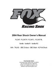
2005 36 RC2 & 36 R Owner's Manual - Fox
2005 36 RC2 & 36 R Owner's Manual - Fox
2005 36 RC2 & 36 R Owner's Manual - Fox

You also want an ePaper? Increase the reach of your titles
YUMPU automatically turns print PDFs into web optimized ePapers that Google loves.
<strong>2005</strong> <strong>36</strong> <strong>RC2</strong> & <strong>36</strong> R<br />
Owner’s <strong>Manual</strong><br />
FOX RACING SHOX<br />
130 Hangar Way<br />
Watsonville, CA 95076<br />
831.274.6500 FAX 831.768.9312<br />
E-Mail: service@foxracingshox.com<br />
Website: www.foxracingshox.com
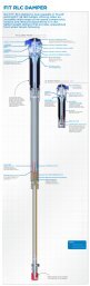
Laser-etched<br />
Rebound<br />
Adjuster<br />
High-Strength<br />
Webbed-Truss<br />
Fork Brace<br />
Optimized<br />
Easton ® EA70 <br />
Steerer<br />
Forged 7050-T6<br />
Aluminum Crown<br />
Laser-etched<br />
TALAS Adjuster<br />
<strong>36</strong>mm Easton<br />
EA70 Stanchions<br />
20mm<br />
Thru-Axle<br />
High- and Low-<br />
Speed Compression<br />
Adjustment Knobs<br />
(<strong>RC2</strong> only)
Table of Contents<br />
Introduction . . . . . . . . . . . . . . . . . . . . . . . . . . . . . . . . . . . . . . . . . . . . . . . . . . . . . . . . . . . . . . . . . . . . . . . 4<br />
Consumer Safety . . . . . . . . . . . . . . . . . . . . . . . . . . . . . . . . . . . . . . . . . . . . . . . . . . . . . . . . . . . . . . . . . . . 4<br />
Important Safety Information . . . . . . . . . . . . . . . . . . . . . . . . . . . . . . . . . . . . . . . . . . . . . . . . . . . . . . . . . 4<br />
Installation . . . . . . . . . . . . . . . . . . . . . . . . . . . . . . . . . . . . . . . . . . . . . . . . . . . . . . . . . . . . . . . . . . . . . . . . 5<br />
Disc Brake Installation . . . . . . . . . . . . . . . . . . . . . . . . . . . . . . . . . . . . . . . 5<br />
Tire Size Limits . . . . . . . . . . . . . . . . . . . . . . . . . . . . . . . . . . . . . . . . . . 6<br />
General Setup Instructions . . . . . . . . . . . . . . . . . . . . . . . . . . . . . . . . . . . . . . . . . . . . . . . . . . . . . . . . . . . 6<br />
Fork Terminology . . . . . . . . . . . . . . . . . . . . . . . . . . . . . . . . . . . . . . . . . 6<br />
Air Pump Instructions . . . . . . . . . . . . . . . . . . . . . . . . . . . . . . . . . . . . . . . 7<br />
Description of TALAS System . . . . . . . . . . . . . . . . . . . . . . . . . . . . . . . . . . . 7<br />
Air Spring Tuning and Setting Sag on TALAS . . . . . . . . . . . . . . . . . . . . . . . . . . . 7<br />
Adjusting Travel on TALAS . . . . . . . . . . . . . . . . . . . . . . . . . . . . . . . . . . . . 8<br />
Damping Adjustment Guidelines . . . . . . . . . . . . . . . . . . . . . . . . . . . . . . . . . . . . . . . . . . . . . . . . . . . . . . 8<br />
Rebound Adjustment . . . . . . . . . . . . . . . . . . . . . . . . . . . . . . . . . . . . . . . 8<br />
High-Speed Compression Adjustment . . . . . . . . . . . . . . . . . . . . . . . . . . . . . . 9<br />
Special “Boost” Feature of High-Speed Compression Adjuster . . . . . . . . . . . . . . . . . . 9<br />
Low-Speed Compression Adjustment . . . . . . . . . . . . . . . . . . . . . . . . . . . . . . . 9<br />
Hydraulic Bottom-Out System . . . . . . . . . . . . . . . . . . . . . . . . . . . . . . . . . . . 9<br />
Check Before Every Ride . . . . . . . . . . . . . . . . . . . . . . . . . . . . . . . . . . . . . . . . . . . . . . . . . . . . . . . . . . . 10<br />
Service Intervals . . . . . . . . . . . . . . . . . . . . . . . . . . . . . . . . . . . . . . . . . . . . . . . . . . . . . . . . . . . . . . . . . . 10<br />
Maintenance Tools and Supplies . . . . . . . . . . . . . . . . . . . . . . . . . . . . . . . . . 11<br />
Seals and Foam Rings . . . . . . . . . . . . . . . . . . . . . . . . . . . . . . . . . . . . . . 11<br />
Structural Inspection . . . . . . . . . . . . . . . . . . . . . . . . . . . . . . . . . . . . . . . 11<br />
Upper Tubes . . . . . . . . . . . . . . . . . . . . . . . . . . . . . . 11<br />
Crowns . . . . . . . . . . . . . . . . . . . . . . . . . . . . . . . . 11<br />
Lower Legs . . . . . . . . . . . . . . . . . . . . . . . . . . . . . . 11<br />
Bushings Technology and Inspection . . . . . . . . . . . . . . . . . . . . . . . . . . . . . . . 12<br />
Showroom Testing . . . . . . . . . . . . . . . . . . . . . . . . . . . 12<br />
Real World Testing . . . . . . . . . . . . . . . . . . . . . . . . . . . 12<br />
Changing Oil . . . . . . . . . . . . . . . . . . . . . . . . . . . . . . . . . . . . . . . . . . . 12<br />
Maintenace Guidelines for the TALAS system . . . . . . . . . . . . . . . . . . . . . . . . . . 14<br />
Tech Tips: Bitter Bear Says... . . . . . . . . . . . . . . . . . . . . . . . . . . . . . . . . . . . . . . . . . . . . . . . . . . . . . . . . 14<br />
Service & Warranty Instructions . . . . . . . . . . . . . . . . . . . . . . . . . . . . . . . . . . . . . . . . . . . . . . . . . . . . . 15<br />
Warranty Policy . . . . . . . . . . . . . . . . . . . . . . . . . . . . . . . . . . . . . . . . . . 15<br />
Warranty Q & A . . . . . . . . . . . . . . . . . . . . . . . . . . . . . . . . . . . . . . . . . . 16<br />
Disclaimer . . . . . . . . . . . . . . . . . . . . . . . . . . . . . . . . . . . . . . . . . . . . . 16<br />
Contact Information . . . . . . . . . . . . . . . . . . . . . . . . . . . . . . . . . . . . . . . . 16<br />
Method of Payment . . . . . . . . . . . . . . . . . . . . . . . . . . . . . . . . . . . . . . . . 16<br />
Method of Shipping . . . . . . . . . . . . . . . . . . . . . . . . . . . . . . . . . . . . . . . . 16<br />
Tuning Notes . . . . . . . . . . . . . . . . . . . . . . . . . . . . . . . . . . . . . . . . . . . . . . . . . . . . . . . . . . . . . . . . . . . . . 17<br />
International Versions<br />
Japanese . . . . . . . . . . . . . . . . . . . . . . . . . . . . . . . . . . . . . . . . . . . . . 18<br />
Français . . . . . . . . . . . . . . . . . . . . . . . . . . . . . . . . . . . . . . . . . . . . . . 34<br />
Italiano . . . . . . . . . . . . . . . . . . . . . . . . . . . . . . . . . . . . . . . . . . . . . . . 49<br />
Deutsch . . . . . . . . . . . . . . . . . . . . . . . . . . . . . . . . . . . . . . . . . . . . . . 64<br />
Español . . . . . . . . . . . . . . . . . . . . . . . . . . . . . . . . . . . . . . . . . . . . . . 79<br />
International Service Centers . . . . . . . . . . . . . . . . . . . . . . . . . . . . . . . . . . . . . . . . . . . . . . . . . . . . . . . . 94
Introduction<br />
Thank you for choosing the <strong>36</strong> for your bicycle. In doing so, you have chosen the best freeride<br />
suspension fork in the world! All <strong>Fox</strong> Racing Shox products are designed, manufactured<br />
and assembled by the finest professionals in the industry. As a consumer and supporter of<br />
<strong>Fox</strong> Racing Shox products, you need to be aware of the importance of setting up your fork<br />
correctly to ensure maximum performance. This manual provides step-by-step instructions of<br />
how to set up and maintain your fork. It is a good idea to keep your receipts with this manual<br />
and refer to it for service and warranty issues.<br />
Consult page 15 for further information about Service and Warranty issues.<br />
Consumer Safety<br />
RIDING A BICYCLE CAN BE DANGEROUS AND CAN RESULT IN DEATH OR SERIOUS<br />
INJURY. TAKE YOUR RESPONSIBILITY TO YOURSELF AND OTHERS SERIOUSLY.<br />
• Maintain your bicycle and suspension.<br />
• Wear protective clothing, eye protection and a helmet.<br />
• Know and ride within your limits.<br />
• Follow IMBA's Rules of the Trail - 1) Ride on open trails only 2) Leave no trace 3) Control<br />
your bicycle 4) Always yield trail 5) Never scare animals 6) Plan ahead.<br />
Important Safety Information<br />
1. Verify that the brakes are installed and adjusted properly before riding the bicycle. Improperly<br />
installed or adjusted brakes can cause loss of control and serious or fatal injuries to the<br />
rider. Use only disc brakes designed by the manufacturer for use on the <strong>Fox</strong> <strong>36</strong>. "V-style"<br />
brakes CANNOT be used on the <strong>Fox</strong> <strong>36</strong>. Do not route brake cables or housing through the<br />
stem.<br />
2. If your fork loses oil, tops out excessively or makes unusual noises, immediately stop riding<br />
and contact <strong>Fox</strong> Racing Shox or an Authorized <strong>Fox</strong> Racing Shox Service Center for inspection.<br />
Continued use of the fork could cause loss of control and serious or fatal injuries. Some<br />
noises such as spring rattle, oil flow and minor clicks are normal.<br />
3. Use only <strong>Fox</strong> Racing Shox replacement parts. Using aftermarket parts on <strong>Fox</strong> FORX will<br />
void the warranty. Aftermarket replacement parts could also cause structural failure resulting<br />
in loss of control and serious or fatal injuries.<br />
4. If mounting the bicycle in a carrier designed to hold a fork by its drop-outs, use caution to<br />
not tilt the bicycle to either side. Tilting the bike with the drop-outs in the carrier can cause<br />
structural damage to the fork. Ensure that the fork is fastened securely with the quick release<br />
and that the rear wheel is properly held. If the bicycle ever tilts or falls from a bicycle carrier,<br />
do not ride it until it is examined by a qualified dealer, Service Center or <strong>Fox</strong> Racing Shox. A<br />
fork leg or drop-out failure could cause loss of control and serious or fatal injuries.<br />
5. The <strong>Fox</strong> <strong>36</strong> does not include reflectors for on-road use. The <strong>Fox</strong> <strong>36</strong> is designed to be used<br />
in competitive off-road riding and racing. Proper reflectors meeting the Consumer Product<br />
Safety Commission’s (CPSC) requirements should be installed if the fork will be used on<br />
public roads.<br />
6. The <strong>Fox</strong> <strong>36</strong> has a crown/steerer/upper-tube assembly. These parts are pressed<br />
together in a one-time, precision press-fit operation. Replacement of any of these parts<br />
requires a complete new assembly. Do not attempt to remove or replace the steerer<br />
or upper tubes independently of the crown. DO NOT ATTEMPT TO ADD THREADS<br />
TO THREADLESS STEERERS. Modifying the crown/steerer/upper-tube assembly as<br />
described here could cause the rider to lose control of the bicycle resulting in serious<br />
or fatal injuries.<br />
4 <strong>2005</strong> <strong>Fox</strong> <strong>36</strong> Owner’s <strong>Manual</strong> | P/N: 605-00-042, Rev. A
Installation<br />
1. The <strong>Fox</strong> <strong>36</strong> should be installed by a qualified bicycle mechanic. Forks installed improperly<br />
are dangerous and can cause loss of control and serious or fatal injuries.<br />
2. Remove existing fork from the bicycle. Remove the crown race from the fork. Measure<br />
the steerer tube length of the existing fork. Transfer this measurement to the <strong>Fox</strong> <strong>36</strong> steerer.<br />
Refer to stem manufacturer's instructions to be sure there will be enough clamping surface<br />
for the stem. If it is necessary to cut the steerer tube, measure twice and cut once. It is also<br />
recommended that a cutting guide be used while cutting the steerer tube.<br />
Note: If the steerer has any nicks or gouges, the crown/steerer assembly must be<br />
replaced. A nick or gouge can cause the steerer to fail prematurely, which can cause<br />
loss of control of the bicycle, resulting in serious injury or death.<br />
3. Install the fork on to the bicycle. Install the stem, stem cap and M6 stem cap bolt on to the<br />
bicycle. Lightly tighten the stem cap bolt so that the fork turns freely without drag or free play.<br />
Disc Brake Installation<br />
4a. The <strong>Fox</strong> <strong>36</strong> is designed to only use disc brakes with disc rotor sizes of 160-205mm. The<br />
<strong>Fox</strong> <strong>36</strong> uses the international XC disc brake bolt pattern. Install disc brake system according<br />
to Disc Brake Manufacturers specifications and torque all fasteners to specification.<br />
Warning: NEVER modify Lower Leg or use Cantilever Rim Brakes.<br />
4b. Route the disc brake hose (for hydraulic disc brakes) or brake cable housing (for mechanical<br />
disc brakes) from the caliper to the inside of the lower leg. Assemble the <strong>Fox</strong> disc brake<br />
hose guide parts as shown in the figure below. Cut your brake hose or brake cable housing to<br />
the correct length and assemble according to disc brake manufacturers specifications. Align<br />
the brake hose guide to be vertical and tighten the disc brake hose guide screw with 2.5mm<br />
hex-key wrench and torque to 8 in-lb (90 N-cm).<br />
<br />
<br />
<br />
<br />
<br />
<br />
<br />
<br />
It is recommended that NEW disc brake pads be installed to ensure proper alignment and to<br />
minimize drag.<br />
<strong>2005</strong> <strong>Fox</strong> <strong>36</strong> Owner’s <strong>Manual</strong> | P/N: 605-00-042, Rev. A 5
Tire Size Limits<br />
5. The <strong>Fox</strong> <strong>36</strong> can accept tire sizes up to 2.80 inches wide. Any tire larger than 26 x 2.60<br />
must be checked for clearance using the following method. With the tire installed and inflated<br />
on the rim, measure the following three dimensions:<br />
Maximum Peak Tire Diameter = 694mm = 27.3 inches<br />
Maximum Edge Tire Diameter = 670mm = 26.4 inches<br />
Maximum Tire Width = 71mm = 2.80 inches<br />
Do not use the tire if ANY measurement exceeds the<br />
maximum dimensions shown above. Using tires larger<br />
than the dimensions shown above is NOT RECOM-<br />
MENDED and can cause serious or fatal injury.<br />
6. Installing the front wheel: Loosen the 4 axle pinch bolts<br />
on the lower leg with a 5mm Hex Key wrench.<br />
b. Using a 5mm Hex Key wrench, turn counter-clockwise to<br />
loosen and remove the Axle.<br />
c. Install the front wheel into the dropouts and install the axle<br />
into the lower leg.<br />
d. Using a 5mm Hex Key wrench, turn clockwise and lightly<br />
tighten the axle to the lower leg to a torque of 19 in-lb (215<br />
N-cm).<br />
e. Tighten the 2 left-side dropout pinch-bolts to a torque 19<br />
in-lb (215 N-cm).<br />
f. Compress the fork on the bike a couple of times to the let<br />
the right-side of the dropout float and settle to its low-friction<br />
point. Tighten the 2 right-side dropout pinch-bolts to a<br />
torque 19 in-lb (215 N-cm).<br />
Maximum<br />
Edge Tire<br />
Diameter<br />
Tire Width<br />
Maximum<br />
Peak Tire<br />
Diameter<br />
7. Setting handlebars straight and torquing stem bolts: Set bike on the ground and sit<br />
on your bike to set the handlebars straight relative to the front wheel. Tighten the stem pinch<br />
bolts and torque fasteners according to the stem manufacturers specifications. Check that<br />
the Handlebar pinch bolts are torqued to the stem manufacturers specifications. Your bike is<br />
ready to ride. Test brakes for proper operation on flat land. Happy Trails!<br />
General Setup Instructions<br />
Fork Terminology<br />
Travel: The total amount the fork compresses.<br />
Sag: The amount the fork compresses with the rider sitting on the bike in a normal riding position.<br />
Compression Damping: This controls the rate at which the fork compresses<br />
Rebound Damping: This controls the rate at which the fork extends.<br />
Preload: The initial force placed on a spring.<br />
Spring Rate: The amount of force required to compress a spring one inch.<br />
6 <strong>2005</strong> <strong>Fox</strong> <strong>36</strong> Owner’s <strong>Manual</strong> | P/N: 605-00-042, Rev. A
Air Pump Instructions<br />
Use a <strong>Fox</strong> High Pressure Air Pump to change pressure on TALAS forks.<br />
1. Remove the air topcap from the top of the left fork leg and connect the pump by threading<br />
the chuck onto the tank valve until the pump gauge registers pressure. If the fork has no air<br />
pressure, the gauge will not register. This takes about 6 turns. Don't over-tighten as it can<br />
damage the pump chuck seal.<br />
2. Increase the pressure by stroking the pump a few cycles. Pressure should increase slowly.<br />
If the pressure increases rapidly, check the pump is properly connected to the tank valve.<br />
3. Decrease the pressure by depressing the black bleed-valve. Push the bleed valve half-way<br />
and hold to allow continuous pressure release. Depress the bleed-valve completely to release<br />
pressure incrementally (micro-adjust).<br />
4. Disconnect the pump by unthreading the chuck. The sound of air loss is from the pump<br />
hose and not the fork.<br />
5. Install the air topcap, and go ride.<br />
Note: When connecting the pump, the hose fills with air resulting in a 10-20PSI lower<br />
gauge reading. Normal pressure range is between 45 and 100psi. DO NOT EXCEED<br />
150psi.<br />
Description of TALAS System<br />
The <strong>Fox</strong> <strong>36</strong> uses the TALAS (Travel Adjustable Linear Air Spring) system. The TALAS knob<br />
changes the travel 3 mm per click, which allows the rider to change the travel from 110mm<br />
to 150mm while riding. THe TALAS air-spring system automatically changes the air pressure<br />
and spring rate when the travel is adjusted, ensuring consistent ride performance for the bike<br />
in all settings. Travel can be changes on the fly at any time.<br />
Air Spring Tuning and Setting Sag on TALAS<br />
Air pressure can be set at any travel. For simplicity, the TALAS Air Spring Guide is for a<br />
150mm travel setting. Use these air pressures as a starting point to set up your TALAS fork:<br />
1. Turn the knob all the way counter-clockwise to achieve 150mm of travel.<br />
2. Hold outer Travel Adjuster knob from spinning and unscrew counter-clockwise the center<br />
TALAS Air Top Cap Knob (Fig. 2) to access the schrader valve.<br />
3. Attach a FOX Racing Shox high pressure pump to the schrader valve.<br />
4. Pump to desired pressure (refer to table below for TALAS Air Spring Guidelines).<br />
5. Remove pump. Check for proper sag before replacing air cap.<br />
6. Check the <strong>Fox</strong> <strong>36</strong> sag table and adjust air pressure as needed.<br />
Fig. 1 TALAS Knob<br />
Fig. 2 TALAS Air Top Cap Knob &<br />
Schrader Valve<br />
<strong>Fox</strong> <strong>36</strong> Air Spring Guidelines<br />
(with fork at 150mm)<br />
Rider Weight<br />
Air Pressure<br />
< 125 lbs. 45 psi<br />
125 - 135 lbs. 48 psi<br />
135 - 145 lbs. 50 psi<br />
145 - 155 lbs. 53 psi<br />
155 - 170 lbs. 55 psi<br />
170 - 185 lbs. 62 psi<br />
185 - 200 lbs. 69 psi<br />
200 - 215 lbs. 76 psi<br />
215 - 230 lbs. 83 psi<br />
230 - 250 lbs. 90 psi<br />
<strong>2005</strong> <strong>Fox</strong> <strong>36</strong> Owner’s <strong>Manual</strong> | P/N: 605-00-042, Rev. A 7
Travel<br />
<strong>Fox</strong> <strong>36</strong> Sag Table<br />
Mtn X<br />
Race<br />
Freeride<br />
Plush<br />
110mm 17mm 28mm<br />
150mm 23mm 38mm<br />
Symptom<br />
Too much sag<br />
Excessive bottoming during<br />
riding<br />
Too little sag<br />
Ride is harsh and never uses<br />
full travel<br />
Do the following:<br />
Increase air pressure in 5 psi<br />
increments<br />
Increase air pressure in 5 psi<br />
increments<br />
Decrease air pressure in 5 psi<br />
increments<br />
Decrease air pressure in 5 psi<br />
increments<br />
Adjusting Travel on TALAS<br />
Travel can be changed either on or off the bike.<br />
Decreasing Travel<br />
From 150mm (full extension) travel, turn the TALAS knob (Fig. 1) clockwise to shorten the travel.<br />
Each click represents 3mm of travel change. There are 15 positions in 3.5 rotations.<br />
Turn knob desired number of clicks, then compress and hold down the fork for a few<br />
seconds. Cycle the fork a few times and it will hold down at its new shorter travel.<br />
Increasing Travel<br />
From shorter travel turn the TALAS knob counter-clockwise to increase travel.<br />
Turn knob desired number of clicks and unweight the fork for a few seconds to allow the<br />
fork to extend.<br />
Damping Adjustment Guidelines<br />
Rebound Adjustment<br />
Rebound damping controls the speed at which the wheel returns from<br />
a compression stroke. Rebound setting is a personal preference and<br />
varies depending on spring preload, spring rate and riding style. The<br />
rebound adjuster is the red knob located on the top of the right fork<br />
leg. The adjuster rotates to stops at each end and has approximately<br />
15 clicks available. It is preset from the factory to 9 clicks out counterclockwise<br />
from the full in position.<br />
Faster<br />
Rebound<br />
Slower<br />
Rebound<br />
<strong>Fox</strong> <strong>36</strong> Rebound Tuning<br />
Adjuster Setting Too Low (-) Setting Too High (+)<br />
Rebound<br />
Adjuster<br />
-Loss of traction & control<br />
-Wallowy ride<br />
-Wheel will not track on terrain<br />
-Front end packs down in bumps<br />
-Ride gets harsh<br />
8 <strong>2005</strong> <strong>Fox</strong> <strong>36</strong> Owner’s <strong>Manual</strong> | P/N: 605-00-042, Rev. A
High-Speed Compression Adjustment<br />
High-Speed Compression damping controls the force it takes to move the fork through the<br />
travel and how the wheel will react to a bump. The High-Speed Adjuster is located at the bottom<br />
of the right fork leg and is the larger of the two blue knobs. To adjust compression knobs,<br />
remove by unscrewing the protective cap. The adjuster rotates to stops at each end and has<br />
15 clicks available. It is preset from the factory at 0 clicks in from the full out position.<br />
<br />
<br />
<br />
<br />
<br />
<br />
<br />
Guide de réglage de la compression <strong>RC2</strong><br />
Adjuster Bump Type Setting Too Low (-) Setting Too High (+)<br />
Low-Speed<br />
Compression Adjuster <br />
High-Speed<br />
Compression Adjuster <br />
-Excessive brake dive<br />
-Wallowy ride<br />
-Bottoms often on<br />
square-edged hits<br />
-Bottoms hard on<br />
g-outs<br />
Special “Boost” Feature of High-Speed Compression Adjuster<br />
No traction in loose<br />
conditions<br />
-Rides harsh with bad<br />
traction<br />
-Use too little of travel<br />
This adjuster is equipped with a max “boost” setting when the adjuster is rotated full firm<br />
clockwise in. This setting offers increased bump force resistance well beyond the adjuster's<br />
linear range up until the stop at full firm.<br />
Note: The High-Speed Compression knob has a feature that allows the insertion of<br />
a 3mm hex key or similar tool to assist in turning this knob. Do not overtorque the<br />
"Boost" knob.<br />
Low-Speed Compression Adjustment<br />
Low-Speed Compression damping controls the influence of rider weight shifts and bike attitude<br />
under braking. The Low-Speed Adjuster is located at the bottom of the right fork leg<br />
and is the smaller of the two blue knobs. This adjuster rotates to stops at each end and has<br />
approximately 17 clicks available. It is preset from the factory at 0 clicks in from the full out<br />
position.<br />
Hydraulic Bottom-Out System<br />
The <strong>Fox</strong> <strong>36</strong> R and <strong>RC2</strong> are equipped with a patent-pending Internally Adjustable Hydraulic<br />
Bottom-Out Control System. This feature can be adjusted inside the cartridge by a <strong>Fox</strong> Service<br />
Center. It comes preset from the factory at the medium setting.<br />
Warning: Do not attempt to disassemble the <strong>Fox</strong> <strong>36</strong> R or <strong>RC2</strong> Closed Cartridge System<br />
unless you are an Authorized <strong>Fox</strong> Racing Shox Service Center with the appropriate<br />
tools.<br />
<strong>2005</strong> <strong>Fox</strong> <strong>36</strong> Owner’s <strong>Manual</strong> | P/N: 605-00-042, Rev. A 9
Check Before Every Ride<br />
1. Check that the 20mm axle pinch bolts are properly torqued to 19 in-lb.<br />
2. Clean the outside of the fork with soap and water and wipe dry with a soft dry rag. Do<br />
not spray water directly on the seal/upper tube junction. DO NOT USE A HIGH PRESSURE<br />
WASHER ON YOUR FORK.<br />
3. Inspect entire exterior of fork for damage. The fork should not be used if any of the<br />
exterior of fork for damage. Please contact your local dealer or <strong>Fox</strong> Racing Shox for further<br />
inspection and repair.<br />
4. Check headset adjustment. Adjust headset if loose according to manufacturer's recommendations.<br />
5. Check that brake cables or hoses are properly routed and fastened.<br />
6. Check that the front and rear brakes operated properly on flat land.<br />
Service Intervals<br />
Performance, safety and the life-span of <strong>Fox</strong> <strong>36</strong> depend on maintenance. If you ride in<br />
extreme conditions, service and maintain your <strong>Fox</strong> <strong>36</strong> more frequently.<br />
Note: In this manual, references being made to the left and right side of the fork are<br />
from the seated rider’s perspective.<br />
The <strong>Fox</strong> <strong>36</strong> requires service at the regular intervals shown below:<br />
Item<br />
Each<br />
Ride<br />
25<br />
Hours<br />
100<br />
Hours<br />
Annually or<br />
200 Hours<br />
18 Months or<br />
300 Hours<br />
Instructions<br />
on Page<br />
Wash and dry exterior<br />
X 10<br />
Clean dust wipers & inspect<br />
/ lube foam rings X<br />
Structural inspection<br />
X 11<br />
Inspect bushings<br />
X 12<br />
Change oil X 12<br />
11<br />
Change Float fluid and<br />
seals in TALAS<br />
X<br />
14<br />
10 <strong>2005</strong> <strong>Fox</strong> <strong>36</strong> Owner’s <strong>Manual</strong> | P/N: 605-00-042, Rev. A
Maintenance Tools and Supplies<br />
Required Tools & Supplies Torque Setting Needed for:<br />
Safety Glasses n/a Eye protection<br />
Bucket / Drain Pan n/a Changing oil and/or travel<br />
Paper towels and/or rags n/a Absorbing oils & fluids<br />
Plastic faced hammer/mallet n/a Tapping bottom shafts<br />
Torque Wrench (Inch pound / Newton<br />
centimeter)<br />
n/a<br />
Torquing fasteners<br />
<strong>Fox</strong> Suspension Fluid n/a Oil change (all forks)<br />
32mm 6 point socket 165 in-lb (1864 N-cm) Topcaps<br />
10mm open-end or socket wrench 50 in-lb (565 N-cm) Left-side bottom nut<br />
15mm open-end or socket wrench 50 in-lb (565 N-cm) Right-side bottom nut<br />
5mm Hex-key wrench or<br />
Hex-key socket<br />
2mm Hex-key wrench or<br />
Hex-key socket<br />
19 in-lb (215 N-cm) Axle and Axle-pinch bolts<br />
11 in-lb (124 N-cm)<br />
4 in-lb (45 N-cm)<br />
Rebound knob (R & <strong>RC2</strong>)<br />
Low- and High-speed compression<br />
knobs (<strong>RC2</strong> only)<br />
Seals and Foam Rings<br />
FOX FORX feature a sealing system designed to keep your fork moving smoothly in all<br />
conditions. There are two parts to the system - the fork seal and the foam ring. The fork<br />
seal features a proprietary scraper lip geometry that keeps dirt out and oil in the fork. The<br />
foam ring sits just below the fork seal. It is saturated with oil and in turn applies oil to the<br />
upper tube as it passes by. This keeps the fork moving up and down smoothly. While FOX<br />
FORX are designed to require minimal maintenance, periodic inspection and cleaning of<br />
the fork sealing system is required. It is normal on FOX FORX for a small amount of oil<br />
and/or grease to accumulate on the upper tubes. This is necessary to keep the fork working<br />
smoothly and to keep out dirt. Further, fork seals are grease packed at the factory. This<br />
grease tends to migrate out of the seals during the break-in period.<br />
Structural Inspection<br />
Upper Tubes<br />
Look for scratches and dings on the upper tubes, which will prematurely wear seals and<br />
bushings. Big scratches and/or dings could compromise the integrity of this product. Contact<br />
a <strong>Fox</strong> Service Center if any of the above are present on your <strong>Fox</strong> <strong>36</strong>.<br />
Crowns<br />
Check the crown for any damage, deformation or cracks. Contact a <strong>Fox</strong> Service Center if<br />
any of the above are present.<br />
Lower Legs<br />
Inspect the lower leg for any damage around the brace region, tube sections, disc brake<br />
mounts and thru-axle dropouts. Check for cracks or flaking in the paint, which could be<br />
an indication of damage to the structure. Inspect the dropouts using the following method:<br />
With the axle in place, torque the pinch bolts to the proper setting (19 in-lb). There<br />
should be a gap present on the under side of the drops. If there is no gap and the walls<br />
are touching, this indicates the pinch bolts have been over-torqued. The material in this<br />
region may be compromised as a result of the over-torqued pinch bolts. Contact a <strong>Fox</strong><br />
Service Center if any of the above are present on your <strong>Fox</strong> <strong>36</strong>.<br />
<strong>2005</strong> <strong>Fox</strong> <strong>36</strong> Owner’s <strong>Manual</strong> | P/N: 605-00-042, Rev. A 11
Bushings Technology and Inspection<br />
<strong>Fox</strong> FORX use hydrodynamic lubrication. In our system, oil is force fed into the tall slotted<br />
bushings during the compression stroke. When the fork cycles up and down the oil is trapped<br />
between bushings, upper tubes and seals.<br />
Thermal expansion rates can cause the bushings to close in on the upper tubes causing high<br />
friction and binding during normal operation. Correct bushing clearance is critical to prevent<br />
binding of fork during normal operation.<br />
Geometric dimensioning and tolerancing is a design practice used to insure parts will work /<br />
fit during the manufacturing process. Bushings are sized before installation and rechecked for<br />
size after installation. Correct bushing tolerance is a diametric clearance of .0015”-.0090”.<br />
Showroom Testing<br />
As you rock the fork back and forth while stopped with the front brake applied, the bushings<br />
have only a small amount of lubricant separating the bushing / upper tube. At this<br />
time you may notice a small amount of bushing play. Fork bushings must have clearance<br />
to perform correctly. Too little clearance will cause high friction, binding or bushing seizure<br />
when hot.<br />
Real World Testing<br />
During normal riding conditions, hydrodynamic lubrication occurs when there is a complete<br />
separation of the upper tube from the bushing by a thin film of oil. Hydrodynamic<br />
lubrication is characterized by very low friction and no wearing of the bushings or shaft<br />
since there is no metal to bushing contact. During hydrodynamic lubrication, normal<br />
bushing clearance will not be noticeable.<br />
Bushings should be checked annually for excessive wear. If excessive fore and aft movement<br />
is detected between the upper tubes and lower legs, contact an Authorized <strong>Fox</strong><br />
Racing Shox Service Center or <strong>Fox</strong> Racing Shox for further instructions. Grasp the lower<br />
legs at the drop outs (axle), then push the fork straight back towards the rear wheel. Now<br />
pull it towards you. Next, grasp the fork near the upper tube/seal junction and try the<br />
same thing. If excessive movement is noticed, refer to page 16 and contact <strong>Fox</strong> Racing<br />
Shox or an Authorized <strong>Fox</strong> Racing Shox Service Center.<br />
Changing Oil<br />
The following tools and supplies will be needed: a 32mm 6-point socket, 10mm open end<br />
wrench or socket, 15mm deep 6-point socket, torque wrench, 2mm hex key wrench, plasticfaced<br />
hammer, small screwdriver, oil drain pan, clean dry lint-free towels.<br />
Quantity Part Number Part Name<br />
1 025-03-004-A 1 qt. bottle of <strong>Fox</strong> Suspension Fluid (7 wt.)<br />
1 241-02-002-C 8mm Crush washer<br />
1 241-01-011 13mm Crush Washer<br />
Oil change on the <strong>Fox</strong> <strong>36</strong> R or <strong>RC2</strong> fork consists of changing the lower leg oil bath in each<br />
leg. This oil bath service can be performed with the common tools listed above and the fork<br />
does not have to be removed from the bicycle. This service will not require any disassembly<br />
of the closed R or <strong>RC2</strong> cartridge.<br />
Warning: Do not attempt to disassemble the <strong>Fox</strong> <strong>36</strong> R or <strong>RC2</strong> Closed Cartridge System<br />
unless you are an Authorized FOX Racing Shox Service Center with the appropriate<br />
tools.<br />
1. Place the bicycle or fork in a stand. Remove the disc brake caliper from the lower leg and<br />
secure it to the handlebars or frame. Using a 5mm Hex Key wrench, loosen the 4 axle pinch<br />
bolts. Using a 5mm Hex-key wrench, unscrew the axle five full revolutions counter-clockwise<br />
and remove from the lower leg. Remove the front wheel from the bike.<br />
12 <strong>2005</strong> <strong>Fox</strong> <strong>36</strong> Owner’s <strong>Manual</strong> | P/N: 605-00-042, Rev. A
2. Place a clean dry oil pan underneath the left side of the fork. Using a 10mm open-end<br />
wrench or socket, loosen the bottom nut 6 full turns. Tap on the bottom nut with a plastic<br />
faced hammer to disengage the plunger shaft from the lower leg. Unscrew and remove the<br />
bottom nut and 8mm crush washer. Pull the lower leg downward until you feel it stop. Let the<br />
oil drain into the oil pan.<br />
3. (<strong>RC2</strong> only) On a <strong>Fox</strong> <strong>36</strong> <strong>RC2</strong> fork, unscrew and remove the Black Protective Compression<br />
Knob Cap. Using a 2mm Hex Key wrench, unscrew the set-screw approximately 2 turns and<br />
remove the low-speed compression adjuster knob. Using a 2mm Hex Key wrench, unscrew<br />
the set-screw approximately 2 turns and remove the high-speed compression adjuster knob.<br />
Be careful to note that the 1/8” diameter Chrome Steel Detent Ball and detent spring are in<br />
the machined hole in the high-speed compression adjuster knob.<br />
<br />
<br />
<br />
<br />
<br />
<br />
<br />
<br />
<br />
<br />
<br />
<br />
<br />
4. Using a 15mm deep socket wrench, unscrew the bottom nut 4 turns. Place a clean dry oil<br />
pan underneath the right side of the fork. Using a 15mm deep socket on the bottom nut (to<br />
protect the adjusters), tap on the bottom nut with a plastic hammer to disengage the base<br />
stud from the lower leg. Remove the bottom nut and 13mm crush washer from the base stud<br />
and set them aside. Push up on the base stud to let the oil bath oil drain out of the fork into<br />
your drain pan.<br />
5. If the oil looks black or a dark gray, you could flush both sides of the lower leg with clean<br />
oil. To flush the lower leg, turn the fork upside-down and add about 20cc into each leg. If the<br />
fork is off the bike you can move it around to get the clean oil all over the inside of the fork.<br />
Let the fork drain into the drain pan until it stops dripping.<br />
6. Turn the bike or fork upside-down, pull up on the lower leg and add 25cc of FOX Suspension<br />
Fluid (7 wt) into the right-side bottom hole (Damper side) of the lower leg. Keeping the<br />
lower leg in the up position, add 15cc of FOX Suspension Fluid (7 wt) into the left-side bottom<br />
hole (TALAS side) of the lower leg.<br />
7. Slide the lower leg down until you can put on a NEW right-side 13mm crush washer with<br />
the old bottom nut. Thread on the bottom nut (2 to 3 turns max.). Using a 15mm deep 6-point<br />
socket, torque the cartridge bottom nut to 50 in-lb.<br />
8. Slide the lower leg down further so the plunger stud on the left side of the fork goes<br />
through the hole of the lower leg. You may need to use thin screwdriver move and align the<br />
plunger shaft so that it goes through the hole of the lower leg. Install a NEW left-side 8mm<br />
crush washer with the old bottom nut. Thread on the bottom nut (2 to 3 turns max.). Using a<br />
10mm socket, torque the plunger bottom nut to 50 in-lb.<br />
<strong>2005</strong> <strong>Fox</strong> <strong>36</strong> Owner’s <strong>Manual</strong> | P/N: 605-00-042, Rev. A 13
9. (RC 2 only) Turn the bicycle right side up. Look at the two compression adjuster shafts<br />
on the bottom of the right side damper. If you cannot find both flats spots, rotate the adjuster<br />
shaft by lightly turning the shaft with needle nose pliers (see figure on page 13). Using a 2mm<br />
hex key wrench, align and install the <strong>RC2</strong> High-speed compression adjuster knob so that the<br />
set screw tightens on the flat spot of the shaft. Be careful that the detent spring and chrome<br />
steel ball are in the top-side of the machined hole. Be careful not to over-torque this knob<br />
because it will cause the knobs to bind. Now align and install the <strong>RC2</strong> low-speed compression<br />
adjuster knob so that the set screw tightens on the flat spot of the shaft. The torque for<br />
both compression knobs is 4 in-lb. Turn the knobs to make sure they turn freely and install the<br />
<strong>RC2</strong> protective cap.<br />
10. Wipe down the lower leg. Reinstall your disc brake caliper and torque fasteners to disc<br />
brake manufacturer’s specifications. Using a 5mm hex key socket and torque wrench, reinstall<br />
the front wheel and thread in the axle and torque to 19 in-lb. Tighten the 2 left side axle<br />
pinch bolts and torque to 19 in-lb. Compress the fork a few times to allow the right side of the<br />
fork leg settle to its low friction spot. Tighten the 2 right side axle pinch bolts and torque to 19<br />
in-lb. Your oil change is complete. Now go ride!<br />
Maintenace Guidelines for the TALAS system<br />
TALAS Forx feature proprietary seals that make it virtually maintenance free.<br />
It is recommended that the TALAS system be rebuilt every eighteen (18) months or 300<br />
hours.<br />
TALAS Forx Seal kit part number is 803-00-212.<br />
Warning: Changing the Float fluid and seals in a TALAS system requires special tools<br />
to charge the IFP piston. It is highly recommended to have an Authorized <strong>Fox</strong> Racing<br />
Shox Service Center performs this maintenance. See page 94 for a list of Service<br />
Centers.<br />
Please note that the slot at the bottom of the left fork leg is NOT an adjustment. It is used<br />
when loosening the bottom nut from the TALAS Base Stud.<br />
Tech Tips: Bitter Bear Says...<br />
Store the bicycle upside down. Inverting the fork allows oil to run down to the foam rings and<br />
keeps them lubed and ready for your next ride.<br />
1. Around the perimeter of the fork seals are small notches. Use a small flat blade screw<br />
driver in these slots to gently pry the seal from the lower legs of the fork. Once loose, raise<br />
them all the way up to the crown on the upper tubes. It is recommended that the tip of the<br />
screwdriver be covered with tape or a piece of material to protect the paint on the fork from<br />
being damaged.<br />
2. Wrap a clean rag around the junction of the upper tubes and the lower legs. This will keep<br />
dirt out while the seals are being cleaned.<br />
3. Use a rag to wipe around the outside diameter of the seal. Wipe until clean.<br />
4. Remove the rags and check the foam rings which will be visible just inside the lower legs.<br />
They should be soaked with oil and should not contain any dirt or debris. If the foam rings are<br />
dry, use a few cc’s of <strong>Fox</strong> Suspension Fluid to saturate them.<br />
5. Wipe the upper tubes and slide the seals down into the lower legs. Carefully press the<br />
seals into place. A thin flat bladed screw driver can be used to press in between the upper<br />
tube and the fork brace. It is recommended that the blade of the screw driver be covered with<br />
tape or a rag to prevent damage to the seal. Inspect that seal is firmly seated against top<br />
surface of the lower leg.<br />
6. Wipe off any excess oil and cycle the fork a few times to check for proper operation.<br />
14 <strong>2005</strong> <strong>Fox</strong> <strong>36</strong> Owner’s <strong>Manual</strong> | P/N: 605-00-042, Rev. A
Service & Warranty Instructions<br />
<strong>Fox</strong> Racing Shox is pleased to offer 48-hour* turnaround for product service, provided the<br />
following steps are taken:<br />
1. In the U.S.A. contact <strong>Fox</strong> Racing Shox at 800.<strong>Fox</strong>.SHOX to obtain a Return Authorization<br />
(R.A.) Number and shipping address. Outside the U.S.A contact the appropriate<br />
International Service Center. Please refer to the list on the Back Cover of this manual,<br />
www.foxracingshox.com or contact <strong>Fox</strong> Racing Shox to determine the Service Center nearest<br />
you.<br />
2. Satisfactory proof of purchase receipt is required for warranty consideration.<br />
3. Mark the Return Authorization (R.A.) Number and the Return Address clearly on the outside<br />
of the package and send to <strong>Fox</strong> Racing Shox or your International Service Center with<br />
shipping charges pre-paid by sender.<br />
4. Include a description of the problem, bicycle information (manufacturer, year and model),<br />
type of <strong>Fox</strong> product, spring rate and return address with daytime phone number.<br />
Warranty Policy<br />
The factory warranty period for your fork is one year (two years in countries in the EU) from<br />
the original date of purchase of the bicycle or fork. A copy of the original purchase receipt<br />
must accompany any fork being considered for warranty service. Warranty is at the full<br />
discretion of <strong>Fox</strong> Racing Shox and will cover only defective materials and workmanship. Warranty<br />
duration and laws may vary from state to state and/or country to country.<br />
Parts, components and assemblies subject to normal wear and tear are not covered under<br />
this warranty.<br />
<strong>Fox</strong> Racing Shox reserves the right to all final warranty or non-warranty decisions.<br />
General Exclusions from this warranty shall include but are not limited to any failures<br />
caused by:<br />
Installation of parts or accessories that are not qualitatively equivalent to genuine <strong>Fox</strong> Racing<br />
Shox parts.<br />
Abnormal strain, neglect, abuse and/or misuse.<br />
Accident and/or collision damage.<br />
Modification of original parts.<br />
Lack of proper maintenance.<br />
Shipping damages or loss (purchase of full value insurance is recommended).<br />
Damage to interior or exterior caused by improper cable routing, rocks, crashes or improper<br />
installation.<br />
Oil changes or service not performed by <strong>Fox</strong> Racing Shox or an Authorized Service Center.<br />
Specific Exclusions from this warranty shall include:<br />
Parts replaced due to normal wear and tear and/or routine maintenance.<br />
Parts subject to normal wear and tear and/or routine maintenance:<br />
Bushings<br />
Seals<br />
Suspension fluids<br />
Dropouts<br />
Disc brake tabs<br />
<strong>Fox</strong> Racing Shox makes no other warranty of any kind, expressed or implied. All implied warranties<br />
of merchantability and fitness for a particular purpose which exceed the obligations and<br />
time limits stated in this warranty are hereby disclaimed by <strong>Fox</strong> Racing Shox and excluded from<br />
this warranty.<br />
<strong>2005</strong> <strong>Fox</strong> <strong>36</strong> Owner’s <strong>Manual</strong> | P/N: 605-00-042, Rev. A 15
Warranty Q & A<br />
Q. What costs are my responsibility during the warranty period?<br />
A. The customer is responsible for all costs of maintenance services, non-warranty repairs,<br />
accident and collision damages, oil, seals, bushings and reducers, and mounting hardware.<br />
Q. What are some examples of “abnormal” strain, neglect or abuse?<br />
A. These terms are general and overlap each other in areas. Specific examples are: Hucking,<br />
ghost riding, big drop, stunt / dare-devil riding, riding with broken parts, riding without oil in<br />
fork, wrong spring rate, etc.<br />
Q. Does the warranty cover incidental costs such as shipping or transportation?<br />
A. No. The warranty is limited to repair of materials and/or workmanship.<br />
Q. May I perform any or all of the recommended maintenance shown in the owner’s manual?<br />
A. You may perform seal and suspension fluid maintenance as well as bushing and drop-out<br />
inspections. If bushings or drop-outs are worn, they should be replaced by <strong>Fox</strong> Racing Shox<br />
or an Authorized Service Center.<br />
Q. May I perform service and repairs on my fork?<br />
A. <strong>Fox</strong> FORX are mostly end user serviceable. Oil and travel changes and damper or spring<br />
replacement can be performed by the consumer. To ensure peak performance, extensive repairs<br />
and service to the fork should be performed by a qualified bicycle suspension mechanic,<br />
<strong>Fox</strong> Racing Shox or an Authorized Service Center. If in doubt as to whether or not you are<br />
capable of fixing your fork, contact <strong>Fox</strong> Racing Shox or an Authorized Service Center.<br />
Disclaimer<br />
<strong>Fox</strong> Racing Shox is not responsible for any damages to you or others arising from riding,<br />
transporting, or other use of your fork or bicycle. In the event that your fork breaks or malfunctions,<br />
<strong>Fox</strong> Racing Shox shall have no liability or obligation beyond the repair or replacement<br />
of your fork pursuant to the terms outlined in the warranty provisions of this manual.<br />
Contact Information<br />
<strong>Fox</strong> Racing Shox<br />
130 Hangar Way<br />
Watsonville, CA 95076<br />
Phone: 831.274.6500<br />
North America: 800.FOX.SHOX (<strong>36</strong>9.7469)<br />
Fax: 831.768.9312<br />
E-mail: service@foxracingshox.com<br />
Website: www.foxracingshox.com<br />
Business Hours: Monday-Friday 8AM-5PM Pacific Time<br />
Method of Payment<br />
Visa, MasterCard and/or Cashier’s Check<br />
Method of Shipping<br />
<strong>Fox</strong> Racing Shox uses UPS Ground service within the USA.<br />
16 <strong>2005</strong> <strong>Fox</strong> <strong>36</strong> Owner’s <strong>Manual</strong> | P/N: 605-00-042, Rev. A
Tuning Notes<br />
<strong>2005</strong> <strong>Fox</strong> <strong>36</strong> Owner’s <strong>Manual</strong> | P/N: 605-00-042, Rev. A 17