Tensar Wall â TW1
Tensar Wall â TW1
Tensar Wall â TW1

Create successful ePaper yourself
Turn your PDF publications into a flip-book with our unique Google optimized e-Paper software.
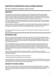
5. Remove all debris from the top of the units using a<br />
brush<br />
6. Place the prepared end of the grid over the rebate<br />
in the block & locate the moulded connectors<br />
around the transverse bar. Ensure that each<br />
aperture of the geogrid is covered by a connector.<br />
The connectors should be split where necessary<br />
6.<br />
7. Position the assembly neatly into the rebate with<br />
the trimmed ribs towards the face next course<br />
(standard units are now used right up to the coping<br />
course). Repeat this procedure for the whole course<br />
ensuring that adjacent lengths of grid are abutted<br />
at the wall face. They should be placed stretcher<br />
bond & arranged so that the downstand is pushed<br />
up against the front of the rebate in the lower unit<br />
7.<br />
8. (a) Place a minimum of three further courses<br />
ensuring they are pushed fully forward and are<br />
square with the previous course. Every course of<br />
blocks should be checked for horizontal and vertical<br />
alignment and the line and level of the wall overall<br />
checked every 3rd course. Any adjustment necessary<br />
may be made using ribs cut from the geogrid or<br />
approved shims, placed in between blocks.<br />
8a.<br />
(b) Any lengths of grid fitted into the wall face<br />
above the level of fill should be temporarily folded<br />
over the top of the wall to provide a free working<br />
area<br />
8b.<br />
(c) Any undue bending of the geogrid should be<br />
avoided.<br />
8c.<br />
<strong>Tensar</strong> Installation Guide for Contractors<br />
2/3<br />
IGC/<strong>TW1</strong>_29.09.09