Tensar Wall â TW1
Tensar Wall â TW1
Tensar Wall â TW1

Create successful ePaper yourself
Turn your PDF publications into a flip-book with our unique Google optimized e-Paper software.
<strong>Tensar</strong> Installation Guide for Contractors<br />
IGC/<strong>TW1</strong>_10.07.08<br />
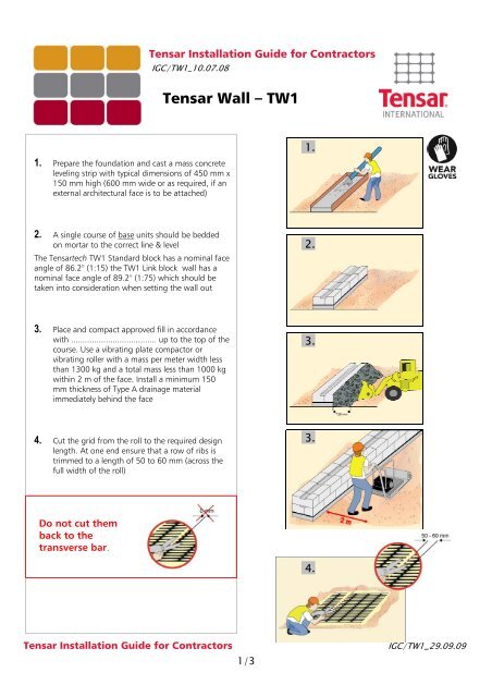
<strong>Tensar</strong> <strong>Wall</strong> – <strong>TW1</strong><br />
1. Prepare the foundation and cast a mass concrete<br />
leveling strip with typical dimensions of 450 mm x<br />
150 mm high (600 mm wide or as required, if an<br />
external architectural face is to be attached)<br />
1.<br />
2. A single course of base units should be bedded<br />
on mortar to the correct line & level<br />
The <strong>Tensar</strong>tech <strong>TW1</strong> Standard block has a nominal face<br />
angle of 86.2° (1:15) the <strong>TW1</strong> Link block wall has a<br />
nominal face angle of 89.2° (1:75) which should be<br />
taken into consideration when setting the wall out<br />
2.<br />
3. Place and compact approved fill in accordance<br />
with ..................................... up to the top of the<br />
course. Use a vibrating plate compactor or<br />
vibrating roller with a mass per meter width less<br />
than 1300 kg and a total mass less than 1000 kg<br />
within 2 m of the face. Install a minimum 150<br />
mm thickness of Type A drainage material<br />
immediately behind the face<br />
3.<br />
4. Cut the grid from the roll to the required design<br />
length. At one end ensure that a row of ribs is<br />
trimmed to a length of 50 to 60 mm (across the<br />
full width of the roll)<br />
3.<br />
Do not cut them<br />
back to the<br />
transverse bar.<br />
4.<br />
<strong>Tensar</strong> Installation Guide for Contractors<br />
1/3<br />
IGC/<strong>TW1</strong>_29.09.09
5. Remove all debris from the top of the units using a<br />
brush<br />
6. Place the prepared end of the grid over the rebate<br />
in the block & locate the moulded connectors<br />
around the transverse bar. Ensure that each<br />
aperture of the geogrid is covered by a connector.<br />
The connectors should be split where necessary<br />
6.<br />
7. Position the assembly neatly into the rebate with<br />
the trimmed ribs towards the face next course<br />
(standard units are now used right up to the coping<br />
course). Repeat this procedure for the whole course<br />
ensuring that adjacent lengths of grid are abutted<br />
at the wall face. They should be placed stretcher<br />
bond & arranged so that the downstand is pushed<br />
up against the front of the rebate in the lower unit<br />
7.<br />
8. (a) Place a minimum of three further courses<br />
ensuring they are pushed fully forward and are<br />
square with the previous course. Every course of<br />
blocks should be checked for horizontal and vertical<br />
alignment and the line and level of the wall overall<br />
checked every 3rd course. Any adjustment necessary<br />
may be made using ribs cut from the geogrid or<br />
approved shims, placed in between blocks.<br />
8a.<br />
(b) Any lengths of grid fitted into the wall face<br />
above the level of fill should be temporarily folded<br />
over the top of the wall to provide a free working<br />
area<br />
8b.<br />
(c) Any undue bending of the geogrid should be<br />
avoided.<br />
8c.<br />
<strong>Tensar</strong> Installation Guide for Contractors<br />
2/3<br />
IGC/<strong>TW1</strong>_29.09.09
9. Insert the tensioning beam (see TN_UniaxialBeam) through<br />
the apertures at the free end of the grid & apply a load<br />
sufficient to remove any slack. Whilst maintaining tension,<br />
place a layer to fill on the grid which is sufficient to retain<br />
it in position when the load is released. Release the<br />
tension & remove the beam<br />
11<br />
10. Place and compact fill in 150 mm lifts keeping units a minimum<br />
of three courses above the fill until the top of<br />
the structure. Repeat the procedures as described in steps<br />
4-10 to the required height of the wall<br />
11. Fill always should be placed by plant such as an excavator<br />
bucket or dozer with an opening bucket, which causes the fill<br />
to cascade onto the grids<br />
12. Compaction should always commence nearest the facing<br />
units, working away toward the free end of the grid<br />
13. No traffic or site plant shall be permitted to travel directly on<br />
the grids<br />
14. The top course of block units should be bonded to the course<br />
below using approved adhesive. Extrude a bead of adhesive<br />
either side of the rebate of the lower units & place the top<br />
course, pressing firmly to locate.<br />
15. In order to achieve good line & level, the coping units should<br />
be bedded on mortar. When alignment of the wall is curved<br />
or angled, the coping units require cutting on site to achieve<br />
best fit<br />
16. If an architectural masonry face is to be attached, the<br />
approved stainless steel ties provided should be inserted into<br />
the slots of the <strong>TW1</strong> Link units, during the laying process. A<br />
rate of three ties to every square metre of face in a staggered<br />
pattern should be used<br />
12<br />
17. The Contractor must fully assess the safety risk associated<br />
with working at height and where appropriate install any<br />
necessary temporary edge protection<br />
13.<br />
The information in this document is of an illustrative nature and is supplied without charge. It does not form part of any contract or intended contract with the user. Final<br />
determination of the suitability of any information or material for the use contemplated and the manner of use is the sole responsibility of the user and the user must assume all risk<br />
and liability in connection therewith.<br />
<strong>Tensar</strong> is a registered trade mark<br />
<strong>Tensar</strong> International Limited<br />
Tel: +44 (0) 1254 262431<br />
Fax: +44 (0) 1254 266867<br />
E-mail: sales@tensar.co.uk<br />
www.tensar-international.com<br />
UK Head Office<br />
Cunningham Court<br />
Shadsworth Business Park<br />
Blackburn<br />
BB1 2QX<br />
United Kingdom<br />
<strong>Tensar</strong> Installation Guide for Contractors<br />
3/3<br />
IGC/<strong>TW1</strong>_29.09.09