LK Series - Lehengoak
LK Series - Lehengoak
LK Series - Lehengoak

Create successful ePaper yourself
Turn your PDF publications into a flip-book with our unique Google optimized e-Paper software.
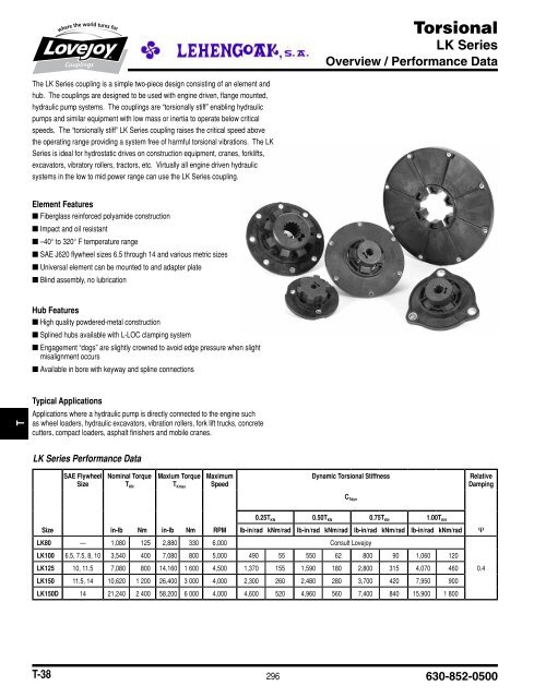
Torsional<br />
<strong>LK</strong> <strong>Series</strong><br />
Overview / Performance Data<br />
ED SLD R VSD UJ SP T D GD HP G MC SF CJ JIS JW<br />
The <strong>LK</strong> <strong>Series</strong> coupling is a simple two-piece design consisting of an element and<br />
hub. The couplings are designed to be used with engine driven, flange mounted,<br />
hydraulic pump systems. The couplings are “torsionally stiff” enabling hydraulic<br />
pumps and similar equipment with low mass or inertia to operate below critical<br />
speeds. The “torsionally stiff” <strong>LK</strong> <strong>Series</strong> coupling raises the critical speed above<br />
the operating range providing a system free of harmful torsional vibrations. The <strong>LK</strong><br />
<strong>Series</strong> is ideal for hydrostatic drives on construction equipment, cranes, forklifts,<br />
excavators, vibratory rollers, tractors, etc. Virtually all engine driven hydraulic<br />
systems in the low to mid power range can use the <strong>LK</strong> <strong>Series</strong> coupling.<br />
JW JIS CJ SF MC G HP GD D T SP UJ VSD R SLD ED<br />
Element Features<br />
■■Fiberglass reinforced polyamide construction<br />
■■Impact and oil resistant<br />
■ ■–40° to 320° F temperature range<br />
■■SAE J620 flywheel sizes 6.5 through 14 and various metric sizes<br />
■■Universal element can be mounted to and adapter plate<br />
■■Blind assembly, no lubrication<br />
Hub Features<br />
■■High quality powdered-metal construction<br />
■■Splined hubs available with L-LOC clamping system<br />
■■Engagement “dogs” are slightly crowned to avoid edge pressure when slight<br />
misalignment occurs<br />
■■Available in bore with keyway and spline connections<br />
Typical Applications<br />
Applications where a hydraulic pump is directly connected to the engine such<br />
as wheel loaders, hydraulic excavators, vibration rollers, fork lift trucks, concrete<br />
cutters, compact loaders, asphalt finishers and mobile cranes.<br />
<strong>LK</strong> <strong>Series</strong> Performa9nce Data<br />
SAE Flywheel<br />
Size<br />
Nominal Torque<br />
T KN<br />
Maxium Torque<br />
T Kmax<br />
Maximum<br />
Speed<br />
Dynamic Torsional Stiffness<br />
0.25T KN 0.50T KN 0.75T KN 1.00T KN<br />
Size<br />
in-lb Nm in-lb Nm RPM lb-in/rad kNm/rad lb-in/rad kNm/rad lb-in/rad kNm/rad lb-in/rad kNm/rad Ψ<br />
<strong>LK</strong>80 — 1,080 125 2,880 330 6,000 Consult Lovejoy<br />
<strong>LK</strong>100 6.5, 7.5, 8, 10 3,540 400 7,080 800 5,000 490 55 550 62 800 90 1,060 120<br />
<strong>LK</strong>125 10, 11.5 7,080 800 14,160 1 600 4,500 1,370 155 1,590 180 2,800 315 4,070 460 0.4<br />
<strong>LK</strong>150 11.5, 14 10,620 1 200 26,400 3 000 4,000 2,300 260 2,480 280 3,700 420 7,950 900<br />
<strong>LK</strong>150D 14 21,240 2 400 58,200 6 000 4,000 4,600 520 4,960 560 7,400 840 15,900 1 800<br />
C Tdyn<br />
Relative<br />
Damping<br />
T-38<br />
296 630-852-0500
Torsional<br />
<strong>LK</strong> <strong>Series</strong><br />
Dimensional Data<br />
1-Piece Flange<br />
2-Piece Flange<br />
Universal + Plate<br />
<strong>LK</strong> <strong>Series</strong> - SAE J6920 Flywheel Application Dimens9ional Data<br />
4, 6 and 8 Dog Patterns<br />
Dependent on Size<br />
ID OD BC FL HD LTB* OAL ML<br />
Nominal Min Bore Max Bore Flange Dimensions Hubstar Assembly<br />
Torque SAE Flange Number & Dia Flange Dimensions<br />
Dimensions<br />
Rating Flywheel Style of Holes Thickness Mounting Length<br />
Size in-lb Nm in mm in mm Size in mm in mm in mm in mm in mm in mm in mm in mm<br />
6.5 1-PIECE 8.500 215.9 7.875 200.0 6 x 0.33 0.55 14<br />
— — — — — —<br />
6 x 8.5<br />
1.26 32 1.34 34 0.906 ± 0.118 23+/-3<br />
7.5 1-PIECE 9.500 241.3 8.750 222.3 8 x 0.33 0.55 14<br />
<strong>LK</strong>100 3,540 400 0.563 15 1.563 40<br />
2.56 65 2.20 56 2.28 58 2.284 ± 0.118 58+/-3<br />
8 1-PIECE 10.375 263.5 9.625 244.5 6 x 0.41 6 x 10.5 0.55 14<br />
1.89 48 1.97 50 1.969 ± 0.118 50+/-3<br />
10 1-PIECE 12.375 314.3 11.625 295.3 8 x 0.41 0.55 14<br />
— — — — — —<br />
<strong>LK</strong>125 7,080 800 0.813 20 2.125 55<br />
10 1-PIECE 12.375 314.3 11.625 295.3 8 x 0.41 0.79 20<br />
1.89 48 1.97 50 1.969 ± 0.118 50+/-3<br />
8 x 10.5<br />
3.35 85<br />
11.5 1-PIECE 13.875 352.4 13.125 333.4 8 x 0.41 0.19 20 1.97 42 2.05 46 1.417 ± 0.118 36+/-3<br />
11.5 1-PIECE 13.875 352.4 3.125 333.4 8 x 0.41 0.79 20<br />
2.09 53 2.09 53 1.299 ± 0.118 33+/-1<br />
<strong>LK</strong>150 10,260 1 200 1.000 25 2.750 70<br />
4.33 110<br />
14 2-PIECE 18.375 466.7 17.250 438.2 8 x 0.50 0.19 5 2.09 53 2.09 53 0.984 ± 0.118 25+/-1<br />
8 x 12.7<br />
<strong>LK</strong>150D 21,240 2 400 1.188 30 2.750 70 14 ** 18.375 466.7 17.250 438.2 8 x 0.50 0.19 5 4.33 110 2.05 52 2.13 54 0.984 ± 0.118 25+/-1<br />
Notes: n * indicates: Other shorter or longer hub lengths available for special requirements.<br />
n ** indicates: <strong>LK</strong> 150D uses 2 Zytel ® elements in parallel with 1 steel plate.<br />
<strong>LK</strong> <strong>Series</strong> Universa9l Elements Dimensi9onal Data<br />
G H TH E OD BC D A S<br />
Hole<br />
Pilot Number Diameter<br />
Size in mm in mm in mm in mm in mm in mm in mm in mm of Holes in mm<br />
<strong>LK</strong>80-6-106 0.55 14.0 0.38 9.7 0.19 4.8 1.12 2.84 5.910 150 5.118 130 3.600 91.4 4.173 106 5 0.33 8.4<br />
<strong>LK</strong>80-6-135 0.39 9.9 0.61 15.5 * * 1.00 25.4 5.315 135 3.937 100 3.629 92.2 5.315 135 3 0.41 10.4<br />
<strong>LK</strong>100-165 0.39 10.0 0.79 20.0 0.16 4.0 1.34 34.0 6.850 174 5.591 142 4.921 125.0 4.921 125 3 0.49 12.5<br />
<strong>LK</strong>100-072 0.39 10.0 0.79 20.0 0.16 4.0 1.34 34.0 7.870 200 6.496 165 4.330 110.0 2.835 72 3 0.65 16.5<br />
<strong>LK</strong>125-195 0.39 10.0 0.55 14.0 0.24 6.0 1.18 30.0 7.680 195 6.496 165 5.315 135.0 5.135 135 6 0.49 12.5<br />
<strong>LK</strong>150-230 0.39 10.0 0.47 12.0 0.20 5.0 1.06 27.0 9.060 230 7.874 200 6.500 165.0 6.496 165 8 0.49 12.5<br />
Notes: n * indicates: <strong>LK</strong>80-6-135 pilots on the O.D.<br />
n Dimensions for universal elements (for non-SAE flywheels, etc.).<br />
JW<br />
JIS<br />
CJ<br />
SF<br />
MC<br />
G<br />
HP<br />
GD<br />
D<br />
T<br />
SP<br />
UJ<br />
VSD<br />
R<br />
SLD<br />
ED<br />
JW JIS CJ SF MC G HP GD D T SP UJ VSD R SLD ED<br />
www.lovejoy-inc.com 297<br />
T-39