
Create successful ePaper yourself
Turn your PDF publications into a flip-book with our unique Google optimized e-Paper software.
catalog<br />
C-bV-0812<br />
ahead of the flow ®<br />
<strong>Ball</strong> <strong>Valves</strong>
Business-to-Business Solutions<br />
Look to NIBCO for technology leadership.<br />
The velocity with which e-business evolves<br />
demands that new products and services<br />
be continuously developed and<br />
introduced to keep our customers at<br />
the center of our business efforts.<br />
NIBCO provides an entire suite of<br />
business-to-business solutions that is<br />
changing the way we interact with customers.<br />
NIBCOpartner.com sm is an exclusive set of secure web applications that allow quick access to<br />
customer-specific information and online order processing. This self-service approach gives you<br />
24/7 access to your order status putting you in total control of your business.<br />
Real time information includes:<br />
• Online order entry<br />
• Viewable invoices & reports<br />
• Inventory availability<br />
• Current price checks<br />
• Order status<br />
• Online library of price sheets, catalogs & submittals<br />
Electronic Data Interchange (EDI) makes it possible to trade business documents at the speed of<br />
light. This technology cuts the cost of each transaction by eliminating the manual labor and paperwork<br />
involved in traditional order taking. This amounts to cost-savings, increased accuracy and<br />
better use of resources.<br />
With EDI, you can trade:<br />
• Purchase orders<br />
• PO Acknowledgements<br />
• Invoices<br />
• Product activity data<br />
• Advanced ship notices<br />
• Remittance advice<br />
Vendor Managed Inventory (VMI), a sophisticated service for automated inventory management,<br />
reduces your overhead by transferring inventory management, order entry and forecasting to<br />
NIBCO. This is an on-going, interactive partnership with NIBCO.<br />
Through automation, VMI brings results:<br />
• Improves customer service<br />
• Optimum inventory efficiencies<br />
• Better forecasting<br />
• Cuts transaction costs<br />
• Peace of mind<br />
• Relief from day-to-day management<br />
NIBCO INC. WORLD HEADQUARTERS • 1516 MIDDLEBURY ST. • ELKHART, IN 46516-4740 • USA • PH: 1.800.234.0227<br />
TECH SERVICES PH:1.888.446.4226 • FAX: 1.888.336.4226 • INTERNATIONAL OFFICE PH: +1.574.295.3327 • FAX: +1.574.295.3455<br />
www.nibco.com
AHEAD OF THE FLOW ®<br />
www.nibco.com<br />
Revision 8/14/2012<br />
Table of Contents<br />
Page<br />
Contents . . . . . . . . . . . . . . . . . . . . . . . . . . . . . . . . . . . . . . . . . . . . . . . . . . . . 3<br />
Bronze <strong>Ball</strong> <strong>Valves</strong>. ....................................... 4-42<br />
Figure Number Key . . . . . . . . . . . . . . . . . . . . . . . . . . . . . . . . . . . . . . . . . 4<br />
Illustrated Index 1 and 2-Pc. <strong>Ball</strong> <strong>Valves</strong> ....................... 5<br />
Illustrated Index 3-Pc. <strong>Ball</strong> <strong>Valves</strong> .............................6<br />
T-560-BR-R-20/Y-20 ........................................7<br />
T-560-BR-R-66/Y-66. ........................................8<br />
T/S-580-70 . . . . . . . . . . . . . . . . . . . . . . . . . . . . . . . . . . . . . . . . . . . . . . . 9<br />
T/S-580-70-66 . . . . . . . . . . . . . . . . . . . . . . . . . . . . . . . . . . . . . . . . . . . . 10<br />
T/S-585-70 . . . . . . . . . . . . . . . . . . . . . . . . . . . . . . . . . . . . . . . . . . . . . . 11<br />
T/S-585-70-66 . . . . . . . . . . . . . . . . . . . . . . . . . . . . . . . . . . . . . . . . . . . . 12<br />
TS/ST-585-70. . . . . . . . . . . . . . . . . . . . . . . . . . . . . . . . . . . . . . . . . . . . . 13<br />
MTT-585-70. . . . . . . . . . . . . . . . . . . . . . . . . . . . . . . . . . . . . . . . . . . . . . 14<br />
T-585-70-CP. . . . . . . . . . . . . . . . . . . . . . . . . . . . . . . . . . . . . . . . . . . . . . 15<br />
T/S-585-70-HC w/Hose Cap and Chain ........................16<br />
T/S-585-70-66-HC w/Hose Cap and Chain............................17<br />
T/S-585-70-SU w/Single Union ..............................18<br />
TS/ST-585-70-SU w/Single Union ............................19<br />
T-585-70-66-ST 250# Steam Rated. ...........................20<br />
T-585/580-70-SV w/Safety Vent. .............................21<br />
T-585/580-70-UL . . . . . . . . . . . . . . . . . . . . . . . . . . . . . . . . . . . . . . . . . . 22<br />
TM-585-70-66 w/ Mounting Pads ............................23<br />
T/S-585-70-W3 Three-Way Valve. ............................24<br />
T/S-585-70-66-W3 Three-Way Valve ..........................25<br />
T/S-590-Y . . . . . . . . . . . . . . . . . . . . . . . . . . . . . . . . . . . . . . . . . . . . . . . 26<br />
T/S-590-Y-66 . . . . . . . . . . . . . . . . . . . . . . . . . . . . . . . . . . . . . . . . . . . . . 27<br />
T-590-Y-UL. . . . . . . . . . . . . . . . . . . . . . . . . . . . . . . . . . . . . . . . . . . . . . . 28<br />
G-590-Y . . . . . . . . . . . . . . . . . . . . . . . . . . . . . . . . . . . . . . . . . . . . . . . . . 29<br />
G-590-Y-66 . . . . . . . . . . . . . . . . . . . . . . . . . . . . . . . . . . . . . . . . . . . . . . 30<br />
T/S-595-Y . . . . . . . . . . . . . . . . . . . . . . . . . . . . . . . . . . . . . . . . . . . . . . . 31<br />
T-595-Y-SS. . . . . . . . . . . . . . . . . . . . . . . . . . . . . . . . . . . . . . . . . . . . . . . 32<br />
T/S-595-Y-66 . . . . . . . . . . . . . . . . . . . . . . . . . . . . . . . . . . . . . . . . . . . . . 33<br />
T-595-Y-66-SS . . . . . . . . . . . . . . . . . . . . . . . . . . . . . . . . . . . . . . . . . . . . 34<br />
TS-595-Y . . . . . . . . . . . . . . . . . . . . . . . . . . . . . . . . . . . . . . . . . . . . . . . . 35<br />
G-595-Y . . . . . . . . . . . . . . . . . . . . . . . . . . . . . . . . . . . . . . . . . . . . . . . . . 36<br />
G-595-Y-66 . . . . . . . . . . . . . . . . . . . . . . . . . . . . . . . . . . . . . . . . . . . . . . 37<br />
T-595-Y-UL. . . . . . . . . . . . . . . . . . . . . . . . . . . . . . . . . . . . . . . . . . . . . . . 38<br />
CS-595-Y-X/EC . . . . . . . . . . . . . . . . . . . . . . . . . . . . . . . . . . . . . . . . . . . 39<br />
CS-595-Y-X-66/EC .........................................40<br />
Pressure/Temperature Ratings ...............................41<br />
Carbon Steel <strong>Ball</strong> <strong>Valves</strong> (Thd, SW, BW). ...................42-56<br />
Figure Number Key . . . . . . . . . . . . . . . . . . . . . . . . . . . . . . . . . . . . . . . . 42<br />
Illustrated Index 1, 2 and 3-Pc. <strong>Ball</strong> <strong>Valves</strong> .....................43<br />
T-560-CS-R-25-LL. .........................................44<br />
T-560-CS-R-25-FS-LL .......................................45<br />
T-560-CS-R-66-LL. .........................................46<br />
T-560-CS-R-66-FS-LL .......................................47<br />
T-570-CS-R-25 . . . . . . . . . . . . . . . . . . . . . . . . . . . . . . . . . . . . . . . . . . . . 48<br />
T-570-CS-R-66 . . . . . . . . . . . . . . . . . . . . . . . . . . . . . . . . . . . . . . . . . . . . 49<br />
TC-580-CS-R-25-LL ........................................50<br />
TC-580-CS-R-66-LL ........................................51<br />
T-580-CS-R-25 . . . . . . . . . . . . . . . . . . . . . . . . . . . . . . . . . . . . . . . . . . . . 52<br />
T-580-CS-R-66 . . . . . . . . . . . . . . . . . . . . . . . . . . . . . . . . . . . . . . . . . . . . 53<br />
TM/KM/BM-590-CS-R-66-FS-LL. .............................54<br />
T/K-595-CS-R-66-LL .......................................55<br />
TM/KM-595-CS-R-66 ......................................56<br />
Visit our website for the most current information.<br />
T-585-S6-R-66-LL. .........................................62<br />
TM/KM/BM-590-S6-R-66-FS-LL ..............................63<br />
T/K-595-S6-R-66-LL. .......................................64<br />
TM/KM-595-S6-R-66 ......................................65<br />
Pressure/Temperature Ratings ............................ 66-67<br />
Carbon Flanged <strong>Ball</strong> <strong>Valves</strong> ...............................68-75<br />
Figure Number Key . . . . . . . . . . . . . . . . . . . . . . . . . . . . . . . . . . . . . . . . 68<br />
Illustrated Index Flanged <strong>Ball</strong> <strong>Valves</strong> ..........................69<br />
Flanged Detail of Unibody Design ............................70<br />
Flanged Detail of Split-Body Design. ..........................71<br />
F-510-CS-R-66-FS .........................................72<br />
F-530-CS-R-66-FS .........................................73<br />
F-515-CS-F-66-FS .........................................74<br />
F-535-CS-F-66-FS .........................................75<br />
Stainless Flanged <strong>Ball</strong> <strong>Valves</strong> .............................76-81<br />
Illustrated Index Flanged <strong>Ball</strong> <strong>Valves</strong> ..........................76<br />
F-510-S6-R-66-FS .........................................77<br />
F-530-S6-R-66-FS .........................................78<br />
F-515-S6-F-66-FS. .........................................79<br />
F-535-S6-F-66-FS. .........................................80<br />
Pressure/Temperature Ratings ...............................81<br />
Options and Accessories .................................82-90<br />
Options and Accessories Index. ..............................82<br />
Bronze <strong>Ball</strong> <strong>Valves</strong> Options and Accessories ....................83<br />
NIB-SEAL ® Technical Data ..................................84<br />
Bronze <strong>Ball</strong> <strong>Valves</strong> Options and Accessories (continued) ..........85<br />
CS/SS <strong>Ball</strong> <strong>Valves</strong> Options and Accessories ....................86<br />
CS/SS Flanged <strong>Ball</strong> <strong>Valves</strong> Options and Accessories .............87<br />
Quick Reference for <strong>Ball</strong> Valve Options ........................88<br />
Seat Materials – PTFE and 15% RPTFE ........................89<br />
Seat Materials – 25% RPTFE, Carbon PTFE and Nylon ............90<br />
System Control Products. ................................91-102<br />
System Control Products Index. ..............................91<br />
<strong>Ball</strong> Valve Actuation and Control .............................92<br />
Circuit Balancing <strong>Valves</strong> ....................................93<br />
<strong>Ball</strong> Valve Actuation Data Sheet .............................94<br />
TM/585-70-66-AP w/Pneumatic Actuator ......................95<br />
TM-585-CV w/Reduced Orifice <strong>Ball</strong> ...........................96<br />
Torque Charts for <strong>Ball</strong> <strong>Valves</strong> ............................. 97-98<br />
Two-Piece and Three-Way Actuator Mounting Data<br />
Bronze T-585-WS and TM/AT-5858. .........................99<br />
Two-Piece Actuator Mounting Data CS/SS T/TC-580 Series ......100<br />
Three-Piece Actuator Mounting Data Bronze 590/595 Series. .....101<br />
Three-Piece Actuator Mounting Data CS/SS TM/KM-595 Series...102<br />
Engineering Data . . . . . . . . . . . . . . . . . . . . . . . . . . . . . . . . . . . . . . 103-114<br />
Engineering Data Index. ...................................103<br />
<strong>Ball</strong> Valve Specifications ..................................104<br />
Temperature Limits of Material .............................105<br />
Flow Data . . . . . . . . . . . . . . . . . . . . . . . . . . . . . . . . . . . . . . . . . . 106-107<br />
Valve Properties Bronze, Brass, Copper and Iron. ........... 108-109<br />
Valve Properties Steel, SS and Alloys .................... 110-111<br />
Valve Installation Tips. ....................................112<br />
Figure Number Comparisons. ...............................113<br />
Valve Warranty . . . . . . . . . . . . . . . . . . . . . . . . . . . . . . . . . . . . . . . . . . 114<br />
Page<br />
Stainless Steel <strong>Ball</strong> <strong>Valves</strong> (Thd, SW, BW). .................57-67<br />
Figure Number Key . . . . . . . . . . . . . . . . . . . . . . . . . . . . . . . . . . . . . . . . 57<br />
Illustrated Index 1, 2 and 3-Pc. <strong>Ball</strong> <strong>Valves</strong> .....................58<br />
T-560-S6-R-66-LL. .........................................59<br />
T-560-S6-R-66-FS-LL . . . . . . . . . . . . . . . . . . . . . . . . . . . . . . . . . . . . . . . 60<br />
T-580-S6-R-66-LL. .........................................61<br />
NIBCO INC. WORLD HEADQUARTERS • 1516 MIDDLEBURY ST. • ELKHART, IN 46516-4740 • USA • PH: 1.800.234.0227<br />
TECH SERVICES PH: 1.888.446.4226 • FAX: 1.888.336.4226 • INTERNATIONAL OFFICE PH: +1.574.295.3327 • FAX: +1.574.295.3455<br />
www.nibco.com<br />
3
AHEAD OF THE FLOW ®<br />
www.nibco.com<br />
Revision 3/31/2011<br />
Bronze <strong>Ball</strong> <strong>Valves</strong><br />
One, Two, and Three-Piece Body<br />
Threaded, Solder and Grooved Ends<br />
Bronze <strong>Ball</strong> Valve Figure Number Key<br />
T-560-BR-R-20- **<br />
End<br />
Connection<br />
Valve<br />
Style<br />
Basic<br />
Material<br />
Seat<br />
Material<br />
Trim<br />
Material<br />
Options<br />
BM - Butt Weld ISO<br />
Mount<br />
G - Grooved<br />
GM - Grooved ISO Mount<br />
KM - Socket Weld ISO<br />
Mount<br />
MTT - Male x Female<br />
Thread<br />
S - Solder<br />
ST - Solder x Thread<br />
T - Thread<br />
TC - Thread (investment<br />
cast carbon body)<br />
TM - Thread ISO Mount<br />
TS - Thread x Solder<br />
560 - One-Piece Body<br />
Reduced Port<br />
600 PSI<br />
580 - Two-Piece<br />
Conventional Port<br />
400 PSI<br />
580-70 - Two-Piece<br />
Conventional Port<br />
600 PSI<br />
585-70 - Two-Piece Full Port<br />
600 PSI<br />
585-CV - Two-Piece with a<br />
Flow Control Port<br />
590 - Three-Piece Body<br />
Conventional Port<br />
600 PSI<br />
595 - Three-Piece Body<br />
Full Port<br />
600 PSI<br />
*BR - Bronze R - Reinforced<br />
Y - Virgin PTFE<br />
* BR only applies to T-560 line.<br />
** 70 only applies to T or S-580-70 and T or S-585-70 series valves.<br />
This key is a guide only and is not intended to infer that every valve combination will be produced.<br />
Key for threaded, socket weld, grooved end ball valves.<br />
20 - Bronze<br />
66 - Stainless Steel<br />
**70 - Bronze/Chrome<br />
Plated <strong>Ball</strong><br />
BSP - British Standard Thread<br />
(Parallel)<br />
BST - British Thread<br />
(Taper)<br />
CP - Chrome Plated<br />
EL - Extended Lever<br />
HC - Hose Cap and Chain<br />
HCL - Horizontal Chain Lever<br />
IC - Integral Check<br />
LL - Locking Lever<br />
M - Memory Stop<br />
NS - NIB-SEAL ® Handle<br />
OL - Oval Locking<br />
OV - Oval Handle<br />
RH - Round Handle<br />
SS - Stainless Steel Externals<br />
ST - Steam Service<br />
SU - Single Union End<br />
SV - Safety Vent<br />
UL - UL Listed<br />
VCL - Vertical Chain Lever<br />
W3 - Three-Way Valve<br />
WH - Wing Handle<br />
X - Oxygen Cleaned<br />
Dezincification<br />
Resistant<br />
De-alloying corrosion, known as ”Dezincification,“ was effectively eradicated from valve products in the 1950s.<br />
Today, however, this problem has returned with the increased use of high-zinc alloys (commonly referred to as<br />
‘Yellow Brass’) in forged and cast valves typically produced outside the United States.<br />
Dezincification selectively removes zinc from the alloy, leaving behind a porous, copper-rich structure that has little mechanical strength. The<br />
physical attributes of an in-service valve with Dezincification includes a white powdery substance or mineral stains on its exterior surface.<br />
What’s the cure? On all bronze valves the metal components in the waterway must not contain more than 15% zinc<br />
in their chemical makeup. As a standard NIBCO ® bronze ball valves are made to be “Dezincification Resistant,”<br />
which is a seal of quality and longevity.<br />
4<br />
NIBCO INC. WORLD HEADQUARTERS • 1516 MIDDLEBURY ST. • ELKHART, IN 46516-4740 • USA • PH: 1.800.234.0227<br />
TECH SERVICES PH: 1.888.446.4226 • FAX: 1.888.336.4226 • INTERNATIONAL OFFICE PH: +1.574.295.3327 • FAX: +1.574.295.3455<br />
www.nibco.com
AHEAD OF THE FLOW ®<br />
www.nibco.com<br />
Revision 7/28/2009<br />
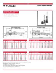
One-Piece and Two-Piece Bronze <strong>Ball</strong> <strong>Valves</strong><br />
Illustrated Index<br />
One-Piece Bronze <strong>Ball</strong> Valve<br />
Up to 600 lb. CWP<br />
Two-Piece Bronze <strong>Ball</strong> Valve<br />
600 lb. CWP<br />
Two-Piece Bronze Hose End <strong>Ball</strong> Valve<br />
600 lb. CWP<br />
T-560-BR-20/T-560-BR-66<br />
Sizes ¹⁄₄" thru 2"<br />
Threaded Ends<br />
Page 7, 8<br />
Two-Piece Bronze Single Union <strong>Ball</strong> Valve<br />
600 lb. CWP<br />
T or S-580-70/T or S-580-70-66<br />
Sizes 1¹⁄₄" thru 3"<br />
T or S-585-70/T or S-585-70-66<br />
Sizes ¹⁄₄" thru 2"<br />
Threaded or Solder Ends • Other End Connections<br />
Page 9-15<br />
Two-Piece Bronze 250 Steam <strong>Ball</strong> Valve<br />
250 lb. SWP<br />
600 lb. CWP<br />
T or S-585-70-HC/T or S-585-70-66-HC<br />
Sizes ¹⁄₂" thru ³⁄₄"<br />
Threaded or Solder Ends<br />
Page 16, 17<br />
Two-Piece Safety Vent Bronze <strong>Ball</strong> Valve<br />
600 lb. CWP<br />
T or S-585-70-SU<br />
Sizes ¹⁄₂" thru 2"<br />
Threaded or Solder Ends<br />
Page 18, 19<br />
Two-Piece UL/LP Gas Bronze <strong>Ball</strong> Valve<br />
250 lb. CWP<br />
T-585-70-66-ST<br />
Sizes ¹⁄₂" thru 2"<br />
Threaded Ends<br />
Page 20<br />
Two-Piece Act. Mount Bronze <strong>Ball</strong> Valve<br />
600 lb. CWP<br />
T-580-70-SV<br />
Sizes 1¹⁄₄" thru 2"<br />
T-585-70-SV<br />
Sizes ¹⁄₄" thru 1"<br />
Threaded Ends<br />
Page 21<br />
Bronze 3-Way <strong>Ball</strong> Valve<br />
400 lb. CWP<br />
T-580-70-UL<br />
Sizes 1¹⁄₄" thru 3"<br />
T-585-70-UL<br />
Sizes ¹⁄₄" thru 1"<br />
Threaded Ends<br />
Page 22<br />
TM-585-70-66<br />
Sizes ¹⁄₂" thru 2¹⁄₂"<br />
Threaded Ends<br />
Page 23<br />
T-585-70-W3<br />
Sizes 1¹⁄₄" thru 2"<br />
T or S-585-70-W3<br />
Sizes ¹⁄₂" thru 1"<br />
Threaded or Solder Ends<br />
Page 24, 25<br />
NIBCO INC. WORLD HEADQUARTERS • 1516 MIDDLEBURY ST. • ELKHART, IN 46516-4740 • USA • PH: 1.800.234.0227<br />
TECH SERVICES PH: 1.888.446.4226 • FAX: 1.888.336.4226 • INTERNATIONAL OFFICE PH: +1.574.295.3327 • FAX: +1.574.295.3455<br />
www.nibco.com<br />
5
AHEAD OF THE FLOW ®<br />
www.nibco.com<br />
Revision 4/18/2011<br />
Three-Piece Bronze <strong>Ball</strong> Valve<br />
Illustrated Index<br />
Dezincification<br />
Resistant<br />
Three-Piece Bronze <strong>Ball</strong> Valve<br />
600 lb. CWP<br />
Three-Piece Bronze <strong>Ball</strong> Valve<br />
600 lb. CWP<br />
175 PSI LP Gas<br />
Three-Piece Bronze <strong>Ball</strong> Valve<br />
600 lb. CWP<br />
T or S-590-Y/T or S-590-Y-66<br />
Sizes ¹⁄₄" thru 3"<br />
Threaded or Solder Ends<br />
Page 26, 27<br />
T-590-Y-UL<br />
Sizes ¹⁄₄" thru 3"<br />
Threaded Ends<br />
Page 28<br />
G-590-Y/G-590-Y-66<br />
Sizes 1¹⁄₂" thru 3"<br />
Grooved Ends<br />
Page 29, 30<br />
Three-Piece Bronze <strong>Ball</strong> Valve<br />
600 lb. CWP<br />
Three-Piece Bronze <strong>Ball</strong> Valve<br />
600 lb. CWP<br />
Three-Piece Bronze <strong>Ball</strong> Valve<br />
600 lb. CWP<br />
T or S-595-Y/T-595-Y-SS/T or S-595-Y-66/<br />
T-595-Y-66-SS<br />
Sizes ¹⁄₄" thru 2¹⁄₂"<br />
Threaded or Solder Ends<br />
Page 31-34<br />
TS-595-Y<br />
Sizes ¹⁄₄" thru 2"<br />
Threaded x Solder Ends<br />
Page 35<br />
G-595-Y/G-595-Y-66<br />
Sizes 1¹⁄₂" thru 2¹⁄₂"<br />
Grooved Ends<br />
Page 36, 37<br />
Three-Piece Bronze <strong>Ball</strong> Valve<br />
600 lb. CWP<br />
175 PSI LP Gas<br />
Three-Piece Bronze <strong>Ball</strong> Valve<br />
200 lb. PSI Medical Gas<br />
Pressure<br />
Temperature<br />
Chart<br />
T-595-Y-UL<br />
Sizes ¹⁄₄" thru 2"<br />
Threaded Ends<br />
Page 38<br />
CS-595-YX/CS-595-YX-66/EC<br />
Sizes ¹⁄₂" thru 2"<br />
Solder Ends<br />
Page 39, 40<br />
Page 41<br />
6<br />
NIBCO INC. WORLD HEADQUARTERS • 1516 MIDDLEBURY ST. • ELKHART, IN 46516-4740 • USA • PH: 1.800.234.0227<br />
TECH SERVICES PH: 1.888.446.4226 • FAX: 1.888.336.4226 • INTERNATIONAL OFFICE PH: +1.574.295.3327 • FAX: +1.574.295.3455<br />
www.nibco.com
AHEAD OF THE FLOW ®<br />
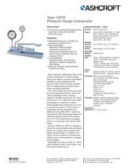
Bronze <strong>Ball</strong> <strong>Valves</strong><br />
One-Piece Body • Reduced Port • Bronze Trim • Blowout-Proof Stem<br />
www.nibco.com<br />
Revision 8/26/2009<br />
Dezincification<br />
Resistant<br />
600 PSI/41.4 Bar Non-Shock Cold Working Pressure u<br />
CONFORMS TO MSS SP-110<br />
MATERIAL LIST<br />
Specification<br />
Part<br />
1. Handle Nut Zinc Plated Steel<br />
2. Identification Plate Aluminum<br />
3. Handle Zinc Plated Steel Clear Chromate<br />
Plastisol Coated<br />
4. 1 Packing Nut Stainless Steel<br />
5. Belleville Washer Zinc Plated Steel<br />
6. Travel Stop Zinc Dichromate Plated Steel<br />
7. Pack Gland Brass ASTM B 16 Alloy C36000<br />
8. Packing Reinforced PTFE<br />
9. Grounding Washer Stainless Steel ASTM A 167 Type 304<br />
10. Thrust Washer Reinforced PTFE<br />
11. Stem Bronze ASTM B 371 Alloy C69430<br />
12. <strong>Ball</strong> Brass ASTM B 124 Alloy C37700<br />
or ASTM B 16 Alloy C36000<br />
13. Seat Ring (2) *PTFE (Y) or Reinforced PTFE (R)<br />
14. Body Insert Bronze ASTM B 584 Alloy C84400<br />
15. Body Bronze ASTM B 584 Alloy C84400<br />
16. Body End Piece Brass ASTM B 16 Alloy C36000 (not shown)<br />
¹⁄₄ and ³⁄₈ size only<br />
T-560-BR- * -20<br />
Threaded<br />
1 ¹⁄₄" -³⁄₄" ASTM A 582 Type 416. 1"-2" 300 Series.<br />
u For detailed Operating Pressure, refer to Pressure Temperature<br />
T-560-BR- * -20<br />
NPT x NPT<br />
DIMENSIONS—WEIGHTS—QUANTITIES<br />
Dimensions<br />
Size A B C D E F G T-560-BR- *-20 Master<br />
In. mm. In. mm. In. mm. In. mm. In. mm. In. mm. In. mm. In. Lbs. Kg. Ctn. Qty.<br />
¹⁄₄ 8 2.63 67 1.34 34 1.63 41 .38 10 4.00 102 1.22 31 10-24 .66 .30 50<br />
³⁄₈ 10 2.63 67 1.34 34 1.63 41 .38 10 4.00 102 1.22 31 10-24 .63 .28 50<br />
¹⁄₂ 15 2.63 67 1.34 34 1.63 41 .38 10 4.00 102 1.22 31 10-24 .59 .27 50<br />
³⁄₄ 20 2.88 73 1.50 38 1.71 43 .50 13 4.00 102 1.22 31 10-24 .82 .37 50<br />
1 25 3.31 84 1.71 43 2.00 51 .63 16 4.69 119 1.34 34 ¹⁄₄-20 1.36 .62 40<br />
1 ¹⁄₄ 32 3.84 98 1.97 50 2.06 52 .81 21 4.69 119 1.50 38 ¹⁄₄-20 2.01 .91 20<br />
1 ¹⁄₂ 40 4.03 102 2.03 52 2.56 65 1.00 25 6.75 171 1.63 41 ¹⁄₄-20 2.75 1.25 20<br />
2 50 4.59 117 2.28 58 2.75 70 1.25 32 6.75 171 2.06 52 ¹⁄₄-20 4.16 1.89 10<br />
Note: G Holes are only tapped for actuated valves.<br />
Chart on page 41.<br />
NIBCO INC. WORLD HEADQUARTERS • 1516 MIDDLEBURY ST. • ELKHART, IN 46516-4740 • USA • PH: 1.800.234.0227<br />
TECH SERVICES PH: 1.888.446.4226 • FAX: 1.888.336.4226 • INTERNATIONAL OFFICE PH: +1.574.295.3327 • FAX: +1.574.295.3455<br />
www.nibco.com<br />
7
AHEAD OF THE FLOW ®<br />
Bronze <strong>Ball</strong> <strong>Valves</strong><br />
One-Piece Body • Reduced Port • Stainless Trim • Vented <strong>Ball</strong> •<br />
Blowout-Proof Stem<br />
600 PSI/41.4 Bar Non-Shock Cold Working Pressure u<br />
www.nibco.com<br />
Revision 8/26/2009<br />
Dezincification<br />
Resistant<br />
CONFORMS TO MSS SP-110<br />
MATERIAL LIST<br />
Specification<br />
Part<br />
1. Handle Nut Stainless Steel 300 Series<br />
2. Identification Plate Aluminum<br />
3. Handle Zinc Plated Steel Clear Chromate<br />
Plastisol Coated<br />
4. 1 Packing Nut Stainless Steel<br />
5. Belleville Washer Zinc Plated Steel<br />
6. Travel Stop Zinc Dichromate Plated Steel<br />
7. Pack Gland Stainless Steel ASTM A 167 Type 316<br />
8. Packing Reinforced PTFE<br />
9. Grounding Washer Stainless Steel ASTM A 240 Type 304<br />
10. Thrust Washer Reinforced PTFE<br />
11. Stem Stainless Steel ASTM A 276 Type 316<br />
12. <strong>Ball</strong> (Vented) Stainless Steel ASTM A 276 Type 316<br />
or ASTM A 351 Type CF8M<br />
13. Seat Ring (2) *PTFE (Y) or Reinforced PTFE (R)<br />
14. Body Insert Bronze ASTM B 584 Alloy C84400<br />
15. Body Bronze ASTM B 584 Alloy C84400<br />
16. Body End Piece Brass ASTM B 16 Alloy C36000 (not shown)<br />
¹⁄₄ and ³⁄₈ size only<br />
T-560-BR- * -66<br />
Threaded<br />
1 ¹⁄₄" -³⁄₄" ASTM A 582 Type 416. 1"-2" 300 Series.<br />
u For detailed Operating Pressure, refer to Pressure Temperature<br />
DIMENSIONS—WEIGHTS—QUANTITIES<br />
T-560-BR- * -66<br />
NPT x NPT<br />
Dimensions<br />
Size A B C D E F G T-560-BR- *-66 Master<br />
In. mm. In. mm. In. mm. In. mm. In. mm. In. mm. In. mm. In. Lbs. Kg. Ctn. Qty.<br />
¹⁄₄ 8 2.63 67 1.34 34 1.63 41 .38 10 4.00 102 1.22 31 10-24 .66 .30 50<br />
³⁄₈ 10 2.63 67 1.34 34 1.63 41 .38 10 4.00 102 1.22 31 10-24 .63 .29 50<br />
¹⁄₂ 15 2.63 67 1.34 34 1.63 41 .38 10 4.00 102 1.22 31 10-24 .59 .27 50<br />
³⁄₄ 20 2.88 73 1.50 38 1.71 43 .50 13 4.00 102 1.22 31 10-24 .82 .37 50<br />
1 25 3.31 84 1.71 43 2.00 51 .63 16 4.69 119 1.34 34 ¹⁄₄-20 1.36 .62 40<br />
1 ¹⁄₄ 32 3.84 98 1.97 50 2.06 52 .81 21 4.69 119 1.50 38 ¹⁄₄-20 2.01 .91 20<br />
1 ¹⁄₂ 40 4.03 102 2.03 52 2.56 65 1.00 25 6.75 171 1.63 41 ¹⁄₄-20 2.75 1.25 20<br />
2 50 4.59 117 2.28 58 2.75 70 1.25 32 6.75 171 2.06 52 ¹⁄₄-20 4.16 1.89 10<br />
Note: G Holes are only tapped for actuated valves.<br />
Chart on page 41.<br />
8<br />
NIBCO INC. WORLD HEADQUARTERS • 1516 MIDDLEBURY ST. • ELKHART, IN 46516-4740 • USA • PH: 1.800.234.0227<br />
TECH SERVICES PH: 1.888.446.4226 • FAX: 1.888.336.4226 • INTERNATIONAL OFFICE PH: +1.574.295.3327 • FAX: +1.574.295.3455<br />
www.nibco.com
AHEAD OF THE FLOW ®<br />
Bronze <strong>Ball</strong> <strong>Valves</strong><br />
Two-Piece Body • Full Port ¹⁄₄"-1" • Conventional Port 1¹⁄₄"-3" •<br />
Bronze Trim • Blowout-Proof Stem<br />
600 PSI/41.4 Bar Non-Shock Cold Working Pressure<br />
150 PSI/10.3 Bar Saturated Steam u<br />
www.nibco.com<br />
Revision 3/31/2011<br />
Dezincification<br />
Resistant<br />
CONFORMS TO MSS SP-110<br />
MATERIAL LIST<br />
Specification<br />
Part<br />
1. Handle Nut Zinc Plated Steel<br />
2. Handle Zinc Plated Steel Clear Chromate<br />
Plastisol Coated<br />
3. Threaded Pack Gland Brass ASTM B 16 Alloy C36000<br />
4. Packing PTFE<br />
5. Stem Silicon Bronze ASTM B 371 Alloy C69430<br />
or ASTM B 99 Alloy C65100<br />
6. Thrust Washer Reinforced PTFE<br />
7. <strong>Ball</strong> Brass ASTM B 124 Alloy C37700 or ASTM B16<br />
Alloy C36000 EACH with Hard Chrome Plate<br />
8. Seat Ring (2) Reinforced PTFE<br />
9. Body Cast Red Bronze ASTM B 584 Alloy C84400<br />
10. Body End Piece Cast Red Bronze ASTM B 584 Alloy C84400<br />
¹⁄₄" size only has a 304 stainless steel grounding washer.<br />
C<br />
T-580-70<br />
Threaded<br />
S-580-70<br />
Solder<br />
B<br />
A<br />
S-580-70<br />
C x C<br />
DIMENSIONS—WEIGHTS—QUANTITIES<br />
Dimensions<br />
D<br />
T-580-70<br />
NPT x NPT<br />
T-580-70 S-580-70 T-580-70 S-580-70<br />
Size A A B C C D T-580-70 S-580-70 Master<br />
In. mm. In. mm. In. mm. In. mm. In. mm. In. mm. In. mm. Lbs. Kg. Lbs. Kg. Ctn. Qty.<br />
† ¹⁄₄ 8 2.00 51 1.75 44 1.75 44 5.00 127 4.75 121 .38 10 .45 .21 .42 .19 100<br />
† ³⁄₈ 10 2.00 51 1.84 47 1.75 44 5.00 127 4.81 122 .38 10 .45 .21 .42 .19 100<br />
† ¹⁄₂ 15 2.44 62 2.56 65 1.88 48 5.19 132 5.25 133 .50 13 .64 .29 .60 .27 100<br />
† ³⁄₄ 20 2.94 75 3.25 83 2.25 57 6.25 159 6.25 159 .75 19 1.33 .60 1.27 .58 50<br />
†1 25 3.34 85 3.75 95 2.38 60 6.44 164 6.63 168 1.00 25 1.79 .81 1.72 .78 40<br />
1 ¹⁄₄ 32 3.94 100 4.00 102 2.63 67 6.75 171 6.75 171 1.00 25 2.17 .98 1.78 .81 20<br />
1 ¹⁄₂ 40 4.31 109 4.44 113 3.00 76 8.88 226 9.00 229 1.25 32 3.27 1.48 2.87 1.30 20<br />
2 50 4.63 118 5.50 140 3.16 80 9.06 230 9.50 241 1.50 38 5.09 2.31 4.60 2.08 10<br />
2 ¹⁄₂ 65 5.84 148 7.28 185 3.50 89 9.66 245 10.38 264 2.00 51 8.25 3.74 8.18 3.71 6<br />
3 80 7.09 180 8.78 223 4.41 112 11.53 293 12.38 314 2.50 64 15.65 7.10 14.86 6.74 4<br />
† NIBCO supplies Full Port T or S-585-70 on this size.<br />
Note: Solder end is designed to be soft-soldered into lines using solders with the melting point not exceeding 500°F.<br />
Higher temperature solders will damage the seat material. See installation sheet packaged with valves.<br />
u For detailed Operating Pressure, refer to Pressure Temperature<br />
Chart on page 41.<br />
NIBCO INC. WORLD HEADQUARTERS • 1516 MIDDLEBURY ST. • ELKHART, IN 46516-4740 • USA • PH: 1.800.234.0227<br />
TECH SERVICES PH: 1.888.446.4226 • FAX: 1.888.336.4226 • INTERNATIONAL OFFICE PH: +1.574.295.3327 • FAX: +1.574.295.3455<br />
www.nibco.com<br />
9
AHEAD OF THE FLOW ®<br />
Bronze <strong>Ball</strong> <strong>Valves</strong><br />
Two-Piece Body • Full Port ¹⁄₄"-1" • Conventional Port 1¹⁄₄"-3" •<br />
Stainless Trim • Blowout-Proof Stem • Vented <strong>Ball</strong><br />
600 PSI/41.4 Bar Non-Shock Cold Working Pressure<br />
150 PSI/10.3 Bar Saturated Steam u<br />
www.nibco.com<br />
Revision 3/31/2011<br />
Dezincification<br />
Resistant<br />
CONFORMS TO MSS SP-110<br />
MATERIAL LIST<br />
Specification<br />
Part<br />
1. Handle Nut Stainless Steel 300 Series<br />
2. Handle Zinc Plated Steel Clear Chromate<br />
Plastisol Coated<br />
3. Threaded Pack Gland Brass ASTM B 16 Alloy C36000<br />
4. Packing PTFE<br />
5. Stem Stainless Steel ASTM A 276 Type 316<br />
6. Thrust Washer Reinforced PTFE<br />
7. <strong>Ball</strong> (Vented) Stainless Steel ASTM A 276 Type 316<br />
or ASTM A 351 Type CF8M<br />
8. Seat Ring (2) Reinforced PTFE<br />
9. Body Bronze ASTM B 584 Alloy C84400<br />
10. Body End Piece Bronze ASTM B 584 Alloy C84400<br />
¹⁄₄" size only has a 304 stainless steel grounding washer.<br />
C<br />
T-580-70-66<br />
Threaded<br />
S-580-70-66<br />
Solder<br />
B<br />
A<br />
S-580-70-66<br />
C x C<br />
DIMENSIONS—WEIGHTS—QUANTITIES<br />
Dimensions<br />
D<br />
T-580-70-66<br />
NPT x NPT<br />
T-580-70-66 S-580-70-66 T-580-70-66 S-580-70-66<br />
Size A A B C C D T-580-70-66 S-580-70-66 Master<br />
In. mm. In. mm. In. mm. In. mm. In. mm. In. mm. In. mm. Lbs. Kg. Lbs. Kg. Ctn. Qty.<br />
† ¹⁄₄ 8 2.00 51 1.75 44 1.75 44 5.00 127 4.75 121 .38 10 .45 .21 .42 .19 100<br />
† ³⁄₈ 10 2.00 51 1.84 47 1.75 44 5.00 127 4.81 122 .38 10 .45 .21 .42 .19 100<br />
† ¹⁄₂ 15 2.44 62 2.56 65 1.88 48 5.19 132 5.25 133 .50 13 .64 .29 .60 .27 100<br />
† ³⁄₄ 20 2.94 75 3.25 83 2.25 57 6.25 159 6.25 159 .75 19 1.33 .60 1.27 .58 50<br />
†1 25 3.34 85 3.75 95 2.38 60 6.44 164 6.63 168 1.00 25 1.79 .81 1.72 .78 40<br />
1 ¹⁄₄ 32 3.94 100 4.00 102 2.63 67 6.75 171 6.75 171 1.00 25 2.33 1.06 1.94 .88 20<br />
1 ¹⁄₂ 40 4.31 109 4.44 113 3.00 76 8.88 226 9.00 229 1.25 32 3.49 1.58 3.10 1.40 20<br />
2 50 4.63 118 5.50 140 3.16 80 9.06 230 9.50 241 1.50 38 5.16 2.34 4.67 2.12 10<br />
2 ¹⁄₂ 65 5.84 148 7.28 185 3.50 89 9.66 245 10.38 264 2.00 51 8.98 4.07 8.92 4.04 6<br />
3 80 7.09 180 8.78 223 4.41 112 11.53 293 12.38 314 2.50 64 17.38 7.88 16.59 7.52 4<br />
† NIBCO supplies Full Port T or S-585-70-66 on this size.<br />
Note: Solder end is designed to be soft-soldered into lines using solders with the melting point not exceeding 500°F.<br />
Higher temperature solders will damage the seat material. See installation sheet packaged with valves.<br />
u For detailed Operating Pressure, refer to Pressure Temperature<br />
Chart on page 41.<br />
10<br />
NIBCO INC. WORLD HEADQUARTERS • 1516 MIDDLEBURY ST. • ELKHART, IN 46516-4740 • USA • PH: 1.800.234.0227<br />
TECH SERVICES PH: 1.888.446.4226 • FAX: 1.888.336.4226 • INTERNATIONAL OFFICE PH: +1.574.295.3327 • FAX: +1.574.295.3455<br />
www.nibco.com
AHEAD OF THE FLOW ®<br />
Bronze <strong>Ball</strong> <strong>Valves</strong><br />
Two-Piece Body • Full Port • Bronze Trim • Blowout-Proof Stem<br />
www.nibco.com<br />
Revision 3/31/2011<br />
Dezincification<br />
Resistant<br />
600 PSI/41.4 Bar Non-Shock Cold Working Pressure<br />
150 PSI/10.3 Bar Saturated Steam u<br />
CONFORMS TO MSS SP-110<br />
MATERIAL LIST<br />
Specification<br />
Part<br />
1. Handle Nut Zinc Plated Steel<br />
2. Handle Zinc Plated Steel Clear Chromate<br />
Plastisol Coated<br />
3. Threaded Pack Gland Brass ASTM B 16 Alloy C36000<br />
4. Packing PTFE<br />
5. Stem Silicon Bronze ASTM B 371 Alloy C69300<br />
or ASTM B 99 Alloy C65100<br />
6. Thrust Washer Reinforced PTFE<br />
7. <strong>Ball</strong> Brass ASTM B 124 Alloy C37700 or ASTM B16<br />
Alloy C36000 EACH with Hard Chrome Plate<br />
8. Seat Ring (2) Reinforced PTFE<br />
9. Body Cast Red Bronze ASTM B 584 Alloy C84400<br />
10. Body End Piece Cast Red Bronze ASTM B 584 Alloy C84400<br />
¹⁄₄" size only has a 304 stainless steel grounding washer.<br />
C<br />
T-585-70<br />
Threaded<br />
S-585-70<br />
Solder<br />
B<br />
A<br />
S-585-70<br />
C x C<br />
DIMENSIONS—WEIGHTS—QUANTITIES<br />
Dimensions<br />
D<br />
T-585-70<br />
NPT x NPT<br />
T-585-70 S-585-70 T-585-70 S-585-70<br />
Size A A B C C D T-585-70 S-585-70 Master<br />
In. mm. In. mm. In. mm. In. mm. In. mm. In. mm. In. mm. Lbs. Kg. Lbs. Kg. Ctn. Qty.<br />
¹⁄₄ 8 2.00 51 1.75 44 1.75 44 5.00 127 4.75 121 .38 10 .45 .21 .42 .19 100<br />
³⁄₈ 10 2.00 51 1.84 47 1.75 44 5.00 127 4.81 122 .38 10 .45 .21 .42 .19 100<br />
¹⁄₂ 15 2.44 62 2.56 65 1.88 48 5.19 132 5.25 133 .50 13 .64 .29 .60 .27 100<br />
³⁄₄ 20 2.94 75 3.25 82 2.25 57 6.25 159 6.25 159 .75 19 1.33 .60 1.27 .58 50<br />
1 25 3.34 85 3.75 95 2.38 60 6.44 164 6.63 168 1.00 25 1.79 .81 1.72 .78 40<br />
1 ¹⁄₄ 32 4.19 106 5.06 128 3.00 76 6.75 171 7.19 183 1.25 32 3.12 1.41 3.18 1.44 20<br />
1 ¹⁄₂ 40 4.72 120 5.99 151 3.16 80 9.06 230 9.69 246 1.50 38 4.78 2.17 5.12 2.32 10<br />
2 50 5.16 131 6.72 170 3.50 89 9.25 235 10.06 256 2.00 51 6.68 3.03 7.10 3.22 8<br />
Note: Solder end is designed to be soft-soldered into lines using solders with the melting point not exceeding 500°F.<br />
Higher temperature solders will damage the seat material. See installation sheet packaged with valves.<br />
u For detailed Operating Pressure, refer to Pressure<br />
Temperature Chart on page 41.<br />
NIBCO INC. WORLD HEADQUARTERS • 1516 MIDDLEBURY ST. • ELKHART, IN 46516-4740 • USA • PH: 1.800.234.0227<br />
TECH SERVICES PH: 1.888.446.4226 • FAX: 1.888.336.4226 • INTERNATIONAL OFFICE PH: +1.574.295.3327 • FAX: +1.574.295.3455<br />
www.nibco.com<br />
11
AHEAD OF THE FLOW ®<br />
Bronze <strong>Ball</strong> <strong>Valves</strong><br />
Two-Piece Body • Full Port • Stainless Trim • Blowout-Proof Stem •<br />
Vented <strong>Ball</strong><br />
600 PSI/41.4 Bar Non-Shock Cold Working Pressure<br />
150 PSI/10.3 Bar Saturated Steam u<br />
www.nibco.com<br />
Revision 3/31/2011<br />
Dezincification<br />
Resistant<br />
CONFORMS TO MSS SP-110<br />
MATERIAL LIST<br />
Specification<br />
Part<br />
1. Handle Nut Stainless Steel 300 Series<br />
2. Handle Zinc Plated Steel Clear Chromate<br />
Plastisol Coated<br />
3. Threaded Pack Gland Brass ASTM B 16 Alloy C36000<br />
4. Packing PTFE<br />
5. Stem Stainless Steel ASTM A 276 Type 316<br />
6. Thrust Washer Reinforced PTFE<br />
7. <strong>Ball</strong> (Vented) Stainless Steel ASTM A 276 Type 316<br />
or ASTM A 351 Type CF8M<br />
8. Seat Ring (2) Reinforced PTFE<br />
9. Body Bronze ASTM B 584 Alloy C84400<br />
10. Body End Piece Bronze ASTM B 584 Alloy C84400<br />
¹⁄₄" size only has a 304 stainless steel grounding washer.<br />
C<br />
T-585-70-66<br />
Threaded<br />
S-585-70-66<br />
Solder<br />
B<br />
A<br />
S-585-70-66<br />
C x C<br />
DIMENSIONS—WEIGHTS—QUANTITIES<br />
T-585-70-66<br />
NPT x NPT<br />
Dimensions<br />
T-585-70-66 S-585-70-66 T-585-70-66 S-585-70-66<br />
Size A A B C C D T-585-70-66 S-585-70-66 Master<br />
In. mm. In. mm. In. mm. In. mm. In. mm. In. mm. In. mm. Lbs. Kg. Lbs. Kg. Ctn. Qty.<br />
¹⁄₄ 8 2.00 51 1.75 44 1.75 44 5.00 127 4.75 121 .38 10 .45 .21 .42 .19 100<br />
³⁄₈ 10 2.00 51 1.84 47 1.75 44 5.00 127 4.81 122 .38 10 .45 .21 .42 .19 100<br />
¹⁄₂ 15 2.44 62 2.56 65 1.88 48 5.19 132 5.25 133 .50 13 .64 .29 .60 .27 100<br />
³⁄₄ 20 2.94 75 3.25 82 2.25 57 6.25 159 6.25 159 .75 19 1.33 .60 1.27 .58 50<br />
1 25 3.34 85 3.75 95 2.38 60 6.44 164 6.63 168 1.00 25 1.79 .81 1.72 .78 40<br />
1 ¹⁄₄ 32 4.19 106 5.06 128 3.00 76 6.75 171 7.19 183 1.25 32 3.34 1.52 3.40 1.55 20<br />
1 ¹⁄₂ 40 4.72 120 5.99 151 3.16 80 9.06 230 9.69 246 1.50 38 4.84 2.20 5.18 2.35 10<br />
2 50 5.16 131 6.72 170 3.50 89 9.25 235 10.06 256 2.00 51 7.41 3.37 7.83 3.56 8<br />
Note: Solder end is designed to be soft-soldered into lines using solders with the melting point not exceeding 500°F.<br />
Higher temperature solders will damage the seat material. See installation sheet packaged with valves.<br />
D<br />
u For detailed Operating Pressure, refer to Pressure<br />
Temperature Chart on page 41.<br />
12<br />
NIBCO INC. WORLD HEADQUARTERS • 1516 MIDDLEBURY ST. • ELKHART, IN 46516-4740 • USA • PH: 1.800.234.0227<br />
TECH SERVICES PH: 1.888.446.4226 • FAX: 1.888.336.4226 • INTERNATIONAL OFFICE PH: +1.574.295.3327 • FAX: +1.574.295.3455<br />
www.nibco.com
AHEAD OF THE FLOW ®<br />
Bronze <strong>Ball</strong> <strong>Valves</strong><br />
Two-Piece Body • Full Port • Bronze Trim • Thread x Solder (TS)<br />
or Solder x Thread End (ST) • Blowout-Proof Stem<br />
600 PSI/41.4 Bar Non-Shock Cold Working Pressure<br />
150 PSI/10.3 Bar Saturated Steam u<br />
www.nibco.com<br />
Revision 3/31/2011<br />
Dezincification<br />
Resistant<br />
CONFORMS TO MSS SP-110<br />
MATERIAL LIST<br />
Specification<br />
Part<br />
1. Handle Nut Zinc Plated Steel<br />
2. Handle Zinc Plated Steel Clear Chromate<br />
Plastisol Coated<br />
3. Threaded Pack Gland Brass ASTM B 16 Alloy C36000<br />
4. Packing PTFE<br />
5. Stem Silicon Bronze ASTM B 371 Alloy C69300<br />
or ASTM B99 Alloy C65100<br />
6. Thrust Washer Reinforced PTFE<br />
7. <strong>Ball</strong> Brass ASTM B 124 Alloy C37700 or ASTM B16<br />
Alloy C36000 EACH with Hard Chrome Plate<br />
8. Seat Ring (2) Reinforced PTFE<br />
9. Body Bronze ASTM B 584 Alloy C84400<br />
10. Body End Piece Bronze ASTM B 584 Alloy C84400<br />
TS-585-70<br />
Threaded x Solder<br />
ST-585-70<br />
Solder x Threaded<br />
C<br />
B<br />
A<br />
ST-585-70<br />
NPT x C<br />
D<br />
TS-585-70<br />
NPT x C<br />
DIMENSIONS—WEIGHTS—QUANTITIES<br />
Dimensions<br />
TS-585-70 ST-585-70<br />
TS-585-70 ST-585-70<br />
Size A A B C C D TS-585-70 ST-585-70 Master<br />
In. mm. In. mm. In. mm. In. mm. In. mm. In. mm. In. mm. Lbs. Kg. Lbs. Kg. Ctn. Qty.<br />
¹⁄₂ 15 2.55 65 2.40 61 1.88 48 5.19 132 5.25 133 .50 13 .71 .32 .62 .28 100<br />
³⁄₄ 20 3.06 78 3.09 78 2.25 57 6.25 159 6.25 159 .75 19 1.31 .60 1.29 .59 50<br />
1 25 3.53 90 3.53 90 2.38 60 6.44 164 6.63 168 1.00 25 2.36 1.07 2.35 1.07 40<br />
1 ¹⁄₄ 32 4.61 117 4.63 118 3.00 76 6.75 171 7.19 183 1.25 32 3.11 1.41 3.18 1.44 20<br />
1 ¹⁄₂ 40 5.32 135 5.32 135 3.16 80 9.06 230 9.69 246 1.50 38 4.82 2.18 5.07 2.30 10<br />
2 50 5.93 151 5.93 151 3.50 89 9.25 235 10.06 256 2.00 51 6.59 2.99 6.34 2.87 8<br />
Note: Solder end is designed to be soft-soldered into lines using solders with the melting point not exceeding 500°F.<br />
Higher temperature solders will damage the seat material. See installation sheet packaged with valves.<br />
u For detailed Operating Pressure, refer to Pressure<br />
Temperature Chart on page 41.<br />
NIBCO INC. WORLD HEADQUARTERS • 1516 MIDDLEBURY ST. • ELKHART, IN 46516-4740 • USA • PH: 1.800.234.0227<br />
TECH SERVICES PH: 1.888.446.4226 • FAX: 1.888.336.4226 • INTERNATIONAL OFFICE PH: +1.574.295.3327 • FAX: +1.574.295.3455<br />
www.nibco.com<br />
13
AHEAD OF THE FLOW ®<br />
www.nibco.com<br />
Revision 3/14/2011<br />
Bronze <strong>Ball</strong> <strong>Valves</strong><br />
Two-Piece Body • Full Port • Bronze Trim • Male x Female Thread Ends •<br />
Blowout-Proof Stem<br />
600 PSI/41.4 Bar Non-Shock Cold Working Pressure<br />
150 PSI/10.3 Bar Saturated Steam u<br />
CONFORMS TO MSS SP-110<br />
MATERIAL LIST<br />
Specification<br />
Part<br />
1. Handle Nut Zinc Plated Steel<br />
2. Handle Zinc Plated Steel Clear Chromate<br />
Plastisol Coated<br />
3. Threaded Pack Gland Brass ASTM B 16 Alloy C36000<br />
4. Packing PTFE<br />
5. Thrust Washer Reinforced PTFE<br />
6. Stem Silicon Bronze ASTM B 371 Alloy C69300<br />
or ASTM B 99 Alloy C65100<br />
7. <strong>Ball</strong> Brass ASTM B 124 Alloy C37700 or ASTM B16<br />
Alloy C36000 EACH with Hard Chrome Plate<br />
8. Seat Ring (2) Reinforced PTFE<br />
9. Body Bronze ASTM B 584 Alloy C84400<br />
10. Male Body End Brass ASTM B 16 Alloy C36000<br />
11. Cap Plug Low Density Polyethylene<br />
MTT-585-70<br />
Male x Female NPT<br />
DIMENSIONS—WEIGHTS—QUANTITIES<br />
Dimensions<br />
Size A B C D MTT-585-70 Master<br />
In. mm. In. mm. In. mm. In. mm. In. mm. Lbs. Kg. Ctn. Qty.<br />
¹⁄₄ 8 2.41 61 5.30 135 1.75 44 .38 10 .43 .19 40<br />
³⁄₈ 10 2.40 61 5.30 135 1.72 44 .38 10 .52 .24 40<br />
¹⁄₂ 15 2.80 71 5.50 140 1.88 48 .50 13 .78 .35 40<br />
³⁄₄ 20 3.40 86 6.59 167 2.25 57 .75 19 1.54 .70 20<br />
1 25 4.00 102 6.99 178 2.38 60 1.00 25 2.71 1.23 20<br />
1 ¹⁄₄ 32 4.58 116 9.18 233 3.00 76 1.25 32 3.56 1.62 10<br />
1 ¹⁄₂ 40 5.20 132 9.53 242 3.16 80 1.50 38 5.34 2.42 6<br />
2 50 5.49 139 9.61 244 3.50 89 2.00 51 6.83 3.10 4<br />
MTT-585-70<br />
Male x Female NPT<br />
u For detailed Operating Pressure, refer to Pressure<br />
Temperature Chart on page 41.<br />
14<br />
NIBCO INC. WORLD HEADQUARTERS • 1516 MIDDLEBURY ST. • ELKHART, IN 46516-4740 • USA • PH: 1.800.234.0227<br />
TECH SERVICES PH: 1.888.446.4226 • FAX: 1.888.336.4226 • INTERNATIONAL OFFICE PH: +1.574.295.3327 • FAX: +1.574.295.3455<br />
www.nibco.com
AHEAD OF THE FLOW ®<br />
Bronze <strong>Ball</strong> <strong>Valves</strong><br />
Two-Piece Body • Full Port • Bronze Trim •<br />
Body with Chrome Plating • Blowout-Proof Stem<br />
600 PSI/41.4 Bar Non-Shock Cold Working Pressure u<br />
www.nibco.com<br />
Revision 3/14/2011<br />
Dezincification<br />
Resistant<br />
CONFORMS TO MSS SP-110<br />
MATERIAL LIST<br />
Specification<br />
Part<br />
1. Handle Nut Zinc Plated Steel<br />
2. Handle Zinc Plated Steel Clear Chromate<br />
Plastisol Coated<br />
3. Threaded Pack Gland Brass ASTM B 16 Alloy C36000<br />
4. Packing PTFE<br />
5. Stem Silicon Bronze ASTM B 371 Alloy C69300<br />
or ASTM B 99 Alloy C65100<br />
6. Thrust Washer Reinforced PTFE<br />
7. <strong>Ball</strong> Brass ASTM B 124 Alloy C37700 or ASTM B16<br />
Alloy C36000 EACH with Hard Chrome Plate<br />
8. Seat Ring (2) Reinforced PTFE<br />
9. Body Chrome Plated Bronze<br />
ASTM B 584 Alloy C84400<br />
10. Body End Piece Chrome Plated Bronze<br />
ASTM B 584 Alloy C84400<br />
1/4" and 3/8" sizes have a 304 stainless steel grounding washer.<br />
T-585-70-CP<br />
Threaded<br />
DIMENSIONS—WEIGHTS—QUANTITIES<br />
Dimensions<br />
Size A B C D T-585-70-CP Master<br />
In. mm. In. mm. In. mm. In. mm. In. mm. Lbs. Kg. Ctn. Qty.<br />
¹⁄₄ 8 2.00 51 1.75 44 5.00 127 .38 10 .45 .21 100<br />
³⁄₈ 10 2.00 51 1.75 44 5.00 127 .38 10 .45 .20 100<br />
¹⁄₂ 15 2.44 62 1.88 48 5.19 132 .50 13 .64 .29 100<br />
³⁄₄ 20 2.94 75 2.25 57 6.25 159 .75 19 1.42 .64 50<br />
1 25 3.34 85 2.38 60 6.44 164 1.00 25 1.79 .81 40<br />
1 ¹⁄₄ 32 4.19 106 3.00 76 6.75 171 1.25 32 3.12 1.41 20<br />
1 ¹⁄₂ 40 4.72 120 3.16 80 9.06 230 1.50 38 4.78 2.17 10<br />
2 50 5.16 131 3.50 89 9.25 235 2.00 51 6.68 3.03 8<br />
T-585-70-CP<br />
NPT x NPT<br />
u For detailed Operating Pressure, refer to Pressure<br />
Temperature Chart on page 41.<br />
NIBCO INC. WORLD HEADQUARTERS • 1516 MIDDLEBURY ST. • ELKHART, IN 46516-4740 • USA • PH: 1.800.234.0227<br />
TECH SERVICES PH: 1.888.446.4226 • FAX: 1.888.336.4226 • INTERNATIONAL OFFICE PH: +1.574.295.3327 • FAX: +1.574.295.3455<br />
www.nibco.com<br />
15
AHEAD OF THE FLOW ®<br />
www.nibco.com<br />
Revision 3/14/2011<br />
Bronze <strong>Ball</strong> <strong>Valves</strong><br />
Two-Piece Body • Full Port • Bronze Trim • ³⁄₄" Hose Connection<br />
with Cap and Chain • Blowout-Proof Stem<br />
600 PSI/41.4 Bar Non-Shock Cold Working Pressure u<br />
CONFORMS TO MSS SP-110<br />
MATERIAL LIST<br />
Specification<br />
Part<br />
1. Handle Nut Zinc Plated Steel<br />
2. Handle Zinc Plated Steel Clear Chromate<br />
Plastisol Coated<br />
3. Threaded Pack Gland Brass ASTM B 16 Alloy C36000<br />
4. Packing PTFE<br />
5. Thrust Washer Reinforced PTFE<br />
6. Stem Silicon Bronze ASTM B 371 Alloy C69300<br />
or ASTM B 99 Alloy C65100<br />
7. <strong>Ball</strong> Brass ASTM B 124 Alloy C37700 or ASTM B16<br />
Alloy C36000 EACH with Hard Chrome Plate<br />
8. Seat Ring (2) Reinforced PTFE<br />
9. Body Bronze ASTM B 584 Alloy C84400<br />
10. Hose Body End ASTM B 124 Alloy C37700<br />
11. 1 Cap Die Cast Brass<br />
12. Gasket Rubber<br />
13. Chain Brass<br />
1 Cap is for hose end thread protection only. Not to be used for pressure containing<br />
purposes.<br />
T-585-70-HC<br />
Threaded x Hose<br />
S-585-70-HC<br />
Solder x Hose<br />
S-585-70-HC<br />
C x Hose<br />
T-585-70-HC<br />
NPT x Hose<br />
DIMENSIONS—WEIGHTS—QUANTITIES<br />
Dimensions<br />
T-585-70-HC S-585-70-HC T-585-70-HC S-585-70-HC<br />
Size A A B C C D T-585-70-HC S-585-70-HC Master<br />
In. mm. In. mm. In. mm. In. mm. In. mm. In. mm. In. mm. Lbs. Kg. Lbs. Kg. Ctn. Qty.<br />
¹⁄₂ 15 2.84 72 2.90 74 1.88 48 5.19 132 5.25 133 .50 13 .80 .36 .74 .34 100<br />
³⁄₄ 20 3.31 84 3.47 88 2.25 57 6.25 159 6.25 159 .75 19 1.46 .66 1.42 .65 50<br />
Note: Solder end is designed to be soft-soldered into lines using solders with the melting point not exceeding 500°F.<br />
Higher temperature solders will damage the seat material. See installation sheet packaged with valves.<br />
u For detailed Operating Pressure, refer to Pressure Temperature<br />
Chart on page 41.<br />
16<br />
NIBCO INC. WORLD HEADQUARTERS • 1516 MIDDLEBURY ST. • ELKHART, IN 46516-4740 • USA • PH: 1.800.234.0227<br />
TECH SERVICES PH: 1.888.446.4226 • FAX: 1.888.336.4226 • INTERNATIONAL OFFICE PH: +1.574.295.3327 • FAX: +1.574.295.3455<br />
www.nibco.com
AHEAD OF THE FLOW ®<br />
www.nibco.com<br />
Revision 8/26/2009<br />
Bronze <strong>Ball</strong> <strong>Valves</strong><br />
Two-Piece Body • Full Port • Stainless Trim • ³⁄₄" Hose Connection<br />
with Cap and Chain • Blowout-Proof Stem<br />
600 PSI/41.4 Bar Non-Shock Cold Working Pressure u<br />
T-585-70-66-HC<br />
Threaded x Hose<br />
CONFORMS TO MSS SP-110<br />
MATERIAL LIST<br />
Specification<br />
Part<br />
1. Handle Nut Stainless Steel 300 Series<br />
2. Handle Zinc Plated Steel Clear Chromate<br />
Plastisol Coated<br />
3. Threaded Pack Gland Brass ASTM B 16 Alloy C36000<br />
4. Packing PTFE<br />
5. Thrust Washer Reinforced PTFE<br />
6. Stem Stainless Steel ASTM A 276 Type 316<br />
7. <strong>Ball</strong> Stainless Steel ASTM A 276 Type 316<br />
or ASTM A 351 Type CF8M<br />
8. Seat Ring (2) Reinforced PTFE<br />
9. Body Bronze ASTM B 584 Alloy C84400<br />
10. Hose Body End ASTM B 124 Alloy C37700<br />
11. 1 Cap Die Cast Brass<br />
12. Gasket Rubber<br />
13. Chain Brass<br />
1 Cap is for hose end thread protection only. Not to be used for pressure containing<br />
purposes.<br />
S-585-70-66-HC<br />
C x Hose<br />
S-585-70-66-HC<br />
C x Hose<br />
T-585-70-66-HC<br />
NPT x Hose<br />
DIMENSIONS—WEIGHTS—QUANTITIES<br />
Dimensions<br />
T-585-70-66-HC S-585-70-66-HC<br />
T-585-70-66-HC S-585-70-66-HC<br />
Size A A B C C D T-585-70-66-HC S-585-70-66-HC Master<br />
In. mm. In. mm. In. mm. In. mm. In. mm. In. mm. In. mm. Lbs. Kg. Lbs. Kg. Ctn. Qty.<br />
¹⁄₂ 15 2.84 72 2.90 74 1.88 48 5.19 132 5.25 133 .50 13 .80 .36 .74 .34 100<br />
³⁄₄ 20 3.31 84 3.47 88 2.25 57 6.25 159 6.25 159 .75 19 1.46 .66 1.42 .65 50<br />
Note: Solder end is designed to be soft-soldered into lines using solders with the melting point not exceeding 500°F.<br />
Higher temperature solders will damage the seat material. See installation sheet packaged with valves.<br />
u For detailed Operating Pressure, refer to Pressure Temperature<br />
Chart on page 41.<br />
NIBCO INC. WORLD HEADQUARTERS • 1516 MIDDLEBURY ST. • ELKHART, IN 46516-4740 • USA • PH: 1.800.234.0227<br />
TECH SERVICES PH: 1.888.446.4226 • FAX: 1.888.336.4226 • INTERNATIONAL OFFICE PH: +1.574.295.3327 • FAX: +1.574.295.3455<br />
www.nibco.com<br />
17
AHEAD OF THE FLOW ®<br />
www.nibco.com<br />
Revision 3/14/2011<br />
Bronze <strong>Ball</strong> <strong>Valves</strong><br />
Two-Piece Body • Full Port • Bronze Trim • Single Union Ends •<br />
Blowout-Proof Stem<br />
600 PSI/41.4 Bar Non-Shock Cold Working Pressure<br />
150 PSI/10.3 Saturated Steam u *<br />
CONFORMS TO MSS SP-110<br />
MATERIAL LIST<br />
Specification<br />
Part<br />
1. Handle Nut Zinc Plated Steel<br />
2. Handle Zinc Plated Steel Clear Chromate<br />
Plastisol Coated<br />
3. Threaded Pack Gland Brass ASTM B 16 Alloy C36000<br />
4. Packing PTFE<br />
5. Thrust Washer Reinforced PTFE<br />
6. Stem Silicon Bronze ASTM B 371 Alloy C69300<br />
or ASTM B 99 Alloy C65100<br />
7. <strong>Ball</strong> Brass ASTM B 124 Alloy C37700 or ASTM B16<br />
Alloy C36000 EACH with Hard Chrome Plate<br />
8. Seat Ring (2) Reinforced PTFE<br />
9. O-Ring FKM<br />
10. Tail Piece ASTM B 124 Alloy C37700<br />
11. Union Nut ASTM B 124 Alloy C37700<br />
or ASTM B 584 Alloy C84400<br />
12. Body End ASTM B 124 Alloy C37700<br />
13. Body Bronze ASTM B 584 Alloy C84400<br />
T-585-70-SU<br />
NPT x NPT<br />
S-585-70-SU<br />
C x C<br />
T-585-70-SU<br />
NPT x NPT<br />
S-585-70-SU<br />
C x C<br />
DIMENSIONS—WEIGHTS—QUANTITIES<br />
Dimensions<br />
T-585-70-SU S-585-70-SU T-585-70-SU S-585-70-SU<br />
Size A A B C C D T-585-70-SU S-585-70-SU Master<br />
In. mm. In. mm. In. mm. In. mm. In. mm. In. mm. In. mm. Lbs. Kg. Lbs. Kg. Ctn. Qty.<br />
¹⁄₂ 15 3.57 91 3.32 84 1.88 48 6.22 158 6.00 152 .50 13 .64 .29 .60 .27 40<br />
³⁄₄ 20 4.13 105 4.20 107 2.25 57 7.28 185 7.25 184 .75 19 1.33 .60 1.27 .58 20<br />
1 25 4.70 119 5.00 127 2.38 60 7.66 195 7.83 199 1.00 25 1.79 .81 1.72 .78 20<br />
1 ¹⁄₄ 32 5.38 137 6.09 155 3.00 76 9.97 253 10.23 260 1.25 32 2.17 .98 3.18 1.44 10<br />
1 ¹⁄₂ 40 6.06 154 7.09 180 3.16 80 10.40 264 10.81 275 1.50 38 3.27 1.48 5.12 2.32 6<br />
2 50 6.38 162 7.66 195 3.50 89 10.50 267 10.97 279 2.00 51 5.09 2.31 7.10 3.22 4<br />
* Consult MSS SP123 for pressure temperature limitations<br />
u For detailed Operating Pressure, refer to Pressure Temperature<br />
Chart on page 41.<br />
18<br />
NIBCO INC. WORLD HEADQUARTERS • 1516 MIDDLEBURY ST. • ELKHART, IN 46516-4740 • USA • PH: 1.800.234.0227<br />
TECH SERVICES PH: 1.888.446.4226 • FAX: 1.888.336.4226 • INTERNATIONAL OFFICE PH: +1.574.295.3327 • FAX: +1.574.295.3455<br />
www.nibco.com
AHEAD OF THE FLOW ®<br />
www.nibco.com<br />
Revision 3/14/2011<br />
Bronze <strong>Ball</strong> <strong>Valves</strong><br />
Two-Piece Body • Full Port • Bronze Trim • Single Union Ends •<br />
Blowout-Proof Stem<br />
600 PSI/41.4 Bar Non-Shock Cold Working Pressure<br />
150 PSI/10.3 Bar Saturated Steam u *<br />
CONFORMS TO MSS SP-110<br />
MATERIAL LIST<br />
Specification<br />
Part<br />
1. Handle Nut Zinc Plated Steel<br />
2. Handle Zinc Plated Steel Clear Chromate<br />
Plastisol Coated<br />
3. Threaded Pack Gland Brass ASTM B 16 Alloy C36000<br />
4. Packing PTFE<br />
5. Thrust Washer Reinforced PTFE<br />
6. Stem Silicon Bronze ASTM B 371 Alloy C69300<br />
or ASTM B 99 Alloy C65100<br />
7. <strong>Ball</strong> Brass ASTM B 124 Alloy C37700 or ASTM B16<br />
Alloy C36000 EACH with Hard Chrome Plate<br />
8. Seat Ring (2) Reinforced PTFE<br />
9. O-Ring FKM<br />
10. Tail Piece ASTM B 124 Alloy C37700<br />
11. Union Nut ASTM B 124 Alloy C37700<br />
or ASTM B 584 Alloy C84400<br />
12. Body End ASTM B 124 Alloy C37700<br />
13. Body Bronze ASTM B 584 Alloy C84400<br />
TS-585-70-SU<br />
Threaded x Solder<br />
ST-585-70-SU<br />
Solder x Threaded<br />
TS-585-70-SU<br />
NPT x C<br />
ST-585-70-SU<br />
C x NPT<br />
DIMENSIONS—WEIGHTS—QUANTITIES<br />
Dimensions<br />
ST-585-70-SU TS-585-70-SU ST-585-70-SU TS-585-70-SU<br />
Size A A B C C D ST-585-70-SU TS-585-70-SU Master<br />
In. mm. In. mm. In. mm. In. mm. In. mm. In. mm. In. mm. Lbs. Kg. Lbs. Kg. Ctn. Qty.<br />
¹⁄₂ 15 3.53 90 3.21 82 1.88 48 6.22 158 6.00 152 .50 132 1.21 .55 1.21 .55 40<br />
³⁄₄ 20 4.22 107 4.10 104 2.25 57 7.28 185 7.25 184 .75 19 1.84 .84 1.84 .84 20<br />
1 25 4.86 123 4.91 125 2.38 60 7.66 195 7.83 199 1.00 25 2.91 1.32 2.91 1.32 20<br />
1 ¹⁄₄ 32 5.79 147 5.63 143 3.00 76 9.97 253 10.23 260 1.25 32 4.39 2.00 4.39 2.00 10<br />
1 ¹⁄₂ 40 6.63 168 6.28 160 3.16 80 10.40 264 10.81 275 1.50 38 6.44 2.93 6.44 2.93 6<br />
2 50 7.10 180 6.89 175 3.50 89 10.50 267 10.91 277 2.00 51 9.44 4.29 9.44 4.29 4<br />
* Consult MSS SP123 for pressure temperature limitations u For detailed Operating Pressure, refer to Pressure Temperature<br />
Chart on page 41.<br />
NIBCO INC. WORLD HEADQUARTERS • 1516 MIDDLEBURY ST. • ELKHART, IN 46516-4740 • USA • PH: 1.800.234.0227<br />
TECH SERVICES PH: 1.888.446.4226 • FAX: 1.888.336.4226 • INTERNATIONAL OFFICE PH: +1.574.295.3327 • FAX: +1.574.295.3455<br />
www.nibco.com<br />
19
AHEAD OF THE FLOW ®<br />
Bronze <strong>Ball</strong> <strong>Valves</strong><br />
Two-Piece Body • 250 Steam Rating • Full Port • 316SS Trim •<br />
Carbon-Filled PTFE Seats • Blowout-Proof Stem • Vented <strong>Ball</strong><br />
600 PSI/41.4 Bar Non-Shock Cold Working Pressure<br />
250 PSI/17.2 Bar Saturated Steam u<br />
www.nibco.com<br />
Revision 8/26/2009<br />
Dezincification<br />
Resistant<br />
CONFORMS TO MSS SP-110<br />
MATERIAL LIST<br />
Specification<br />
Part<br />
1. Handle Nut 300 Series Stainless Steel<br />
2. Handle Stainless Steel Plastisol Coated<br />
3. Threaded Pack Gland Brass ASTM B 16 Alloy C36000<br />
4. Packing Carbon Filled PTFE<br />
5. Thrust Washer Carbon Filled PTFE<br />
6. Stem Stainless Steel ASTM A 276 Type 316<br />
7. <strong>Ball</strong> (Vented) Stainless Steel ASTM A 276 Type 316<br />
or ASTM A 351 Type CF8M<br />
8. Seat Ring (2) Carbon Filled PTFE<br />
9. Body Bronze ASTM B 61 Alloy C92200<br />
10. Body End Piece Bronze ASTM B 584 Alloy C84400<br />
T-585-70-66-ST<br />
Threaded<br />
DIMENSIONS—WEIGHTS—QUANTITIES<br />
Dimensions<br />
Size A B C D T-585-70-66-ST Master<br />
In. mm. In. mm. In. mm. In. mm. In. mm. Lbs. Kg. Ctn. Qty.<br />
¹⁄₂ 15 2.44 62 1.88 48 5.19 132 .50 13 .64 .29 10<br />
³⁄₄ 20 2.94 75 2.25 57 6.25 159 .75 19 1.33 .60 5<br />
1 25 3.34 85 2.38 61 6.44 164 1.00 25 1.79 .81 5<br />
1 ¹⁄₄ 32 4.19 106 3.00 76 6.75 171 1.25 32 2.17 .98 5<br />
1 ¹⁄₂ 40 4.72 120 3.16 80 9.06 230 1.50 38 3.27 1.48 5<br />
2 50 5.16 131 3.50 89 9.25 235 2.00 51 5.09 2.31 2<br />
T-585-70-66-ST<br />
NPT x NPT<br />
u For detailed Operating Pressure, refer to Pressure Temperature<br />
Chart on page 41.<br />
20<br />
NIBCO INC. WORLD HEADQUARTERS • 1516 MIDDLEBURY ST. • ELKHART, IN 46516-4740 • USA • PH: 1.800.234.0227<br />
TECH SERVICES PH: 1.888.446.4226 • FAX: 1.888.336.4226 • INTERNATIONAL OFFICE PH: +1.574.295.3327 • FAX: +1.574.295.3455<br />
www.nibco.com
AHEAD OF THE FLOW ®<br />
Bronze <strong>Ball</strong> <strong>Valves</strong><br />
Two-Piece Body • Full Port ¹⁄₄"-1" • Conventional Port 1¹⁄₄"-2" • Bronze Trim •<br />
Safety Vent ® for Pneumatic Applications • Blowout-Proof Stem<br />
600 PSI/41.4 Bar Non-Shock Cold Working Pressure<br />
www.nibco.com<br />
Revision 11/3/2008<br />
Dezincification<br />
Resistant<br />
O.S.H.A. 1910.147<br />
MATERIAL LIST<br />
Specification<br />
Part<br />
1. Handle Nut Zinc Plated Steel<br />
2. Handle Zinc Plated Steel Clear Chromate<br />
Plastisol Coated<br />
3. Threaded Pack Gland Brass ASTM B 16 Alloy C36000<br />
4. Packing PTFE<br />
5. Stem Silicon Bronze ASTM B 371 Alloy C69430<br />
or C69300 or ASTM B 99 Alloy C65100<br />
6. Thrust Washer Reinforced PTFE<br />
7. <strong>Ball</strong> Brass ASTM B 124 Alloy C37700 or ASTM B16<br />
Alloy C36000 EACH with Hard Chrome Plate<br />
8. Seat Ring (2) Reinforced PTFE<br />
9. Body Bronze ASTM B 584 Alloy C84400<br />
10. Body End Piece Bronze ASTM B 584 Alloy C84400<br />
11. Locking Device 300 Series Stainless Steel<br />
Note: A Buna O-ring is installed on the upstream side behind the seat ring.<br />
Maximum temperature of Buna is 180° F. (Not Shown)<br />
T-585-70-SV<br />
¹⁄₄"-1" Full Port<br />
Threaded<br />
T-580-70-SV<br />
1¹⁄₄"-2" Conventional Port<br />
Threaded<br />
DIMENSIONS—WEIGHTS—QUANTITIES<br />
Dimensions<br />
T-585-70-SV<br />
Size A B C D T-580-70-SV Master<br />
In. mm. In. mm. In. mm. In. mm. In. mm. Lbs. Kg. Ctn. Qty.<br />
† ¹⁄₄ 8 2.00 51 1.75 44 5.00 127 .38 10 .49 .22 100<br />
† ³⁄₈ 10 2.00 51 1.75 44 5.00 127 .38 10 .48 .22 100<br />
† ¹⁄₂ 15 2.44 62 1.88 48 5.19 132 .50 13 .68 .31 100<br />
† ³⁄₄ 20 2.94 75 2.25 57 6.25 159 .75 19 1.38 .63 50<br />
†1 25 3.34 85 2.38 60 6.44 164 1.00 25 1.99 .90 40<br />
1 ¹⁄₄ 32 3.94 100 2.63 67 6.75 171 1.00 25 2.37 1.07 20<br />
1 ¹⁄₂ 40 4.31 109 3.00 76 8.88 226 1.25 32 3.57 1.62 20<br />
2 50 4.63 118 3.16 80 9.06 230 1.50 38 5.20 2.36 10<br />
NIBCO T-585-70-SV Safety Vent ® lock-out ball valves provide positive energy isolation<br />
per O.S.H.A. standard 1910.147. <strong>Valves</strong> lock in closed position only. For compressed air.<br />
To order specify T-585-70-SV/T-580-70-SV.<br />
† NIBCO Supplies Full Port T-585-70-SV on this size.<br />
T-585-70-SV<br />
T-580-70-SV<br />
NPT x NPT<br />
NIBCO INC. WORLD HEADQUARTERS • 1516 MIDDLEBURY ST. • ELKHART, IN 46516-4740 • USA • PH: 1.800.234.0227<br />
TECH SERVICES PH: 1.888.446.4226 • FAX: 1.888.336.4226 • INTERNATIONAL OFFICE PH: +1.574.295.3327 • FAX: +1.574.295.3455<br />
www.nibco.com<br />
21
AHEAD OF THE FLOW ®<br />
Bronze <strong>Ball</strong> <strong>Valves</strong><br />
Two-Piece Body • Full Port ¹⁄₄"-1" • Conventional Port 1¹⁄₄"-3" •<br />
Bronze Trim • Blowout-Proof Stem • UL Listed<br />
250 PSI/17.2 Bar Non-Shock LP Gas per UL842<br />
www.nibco.com<br />
Revision 11/3/2008<br />
Dezincification<br />
Resistant<br />
CONFORMS TO MSS SP-110 •<br />
CSA certified to ANSI/ASME B 16.33 and CGA 3.16<br />
for Natural and Propane Gas to 125 PSIG (¹⁄₄"-1")<br />
MATERIAL LIST<br />
Specification<br />
Part<br />
1. Handle Nut Zinc Plated Steel<br />
2. Handle Zinc Plated Steel Clear Chromate<br />
Plastisol Coated<br />
3. Threaded Pack Gland Brass ASTM B 16 Alloy C36000<br />
4. Packing PTFE<br />
5. Stem Silicon Bronze ASTM B 371 Alloy C69430<br />
or ASTM B 99 Alloy C65100<br />
6. Thrust Washer Reinforced PTFE<br />
7. <strong>Ball</strong> Brass ASTM B 124 Alloy C37700 or ASTM B16<br />
Alloy C36000 EACH with Hard Chrome Plate<br />
8. Seat Ring (2) Reinforced PTFE<br />
9. Body Bronze ASTM B 584 Alloy C84400<br />
10. Body End Piece Bronze ASTM B 584 Alloy C84400<br />
T-585-70-UL<br />
¹⁄₄"-1" Full Port CSA<br />
Threaded<br />
T-580-70-UL<br />
1¹⁄₄"-3" Conventional Port<br />
Threaded<br />
UL Only<br />
UL Listed For:<br />
YSDT LP gas shut-off<br />
YQNZ Compressed gas shut-off<br />
YRPV Gas shut-off<br />
YRBX Flammable liquid shut-off<br />
MHKZ Manual valves<br />
CUL Listed For:<br />
YSDT7 LP gas shut-off for Canada<br />
Service<br />
A - Air or non-toxic, non-flammable gas<br />
G - City gas supplied by public utilities<br />
GA - Gasoline<br />
LP - Liquified petroleum gas, 250 PSI max.<br />
02 - No. 1 and 2 fuel oil<br />
04 - No. 4 fuel oil<br />
05 - No. 5 fuel oil<br />
06 - No. 6 fuel oil<br />
DIMENSIONS—WEIGHTS—QUANTITIES<br />
Dimensions<br />
T-585-70-UL<br />
Size A B C D T-580-70-UL Master<br />
In. mm. In. mm. In. mm. In. mm. In. mm. Lbs. Kg. Ctn. Qty.<br />
†¹⁄₄ 8 2.00 51 1.75 44 5.00 127 .38 10 .45 .21 100<br />
† ³⁄₈ 10 2.00 51 1.75 44 5.00 127 .38 10 .45 .20 100<br />
† ¹⁄₂ 15 2.44 62 1.88 48 5.19 132 .50 13 .64 .29 100<br />
† ³⁄₄ 20 2.94 75 2.25 57 6.25 159 .75 19 1.33 .60 50<br />
†1 25 3.34 85 2.38 60 6.44 164 1.00 25 1.79 .81 40<br />
1 ¹⁄₄ 32 3.94 100 2.63 67 6.75 171 1.00 25 2.17 .98 20<br />
1 ¹⁄₂ 40 4.31 109 3.00 76 8.88 226 1.25 32 3.27 1.48 20<br />
2 50 4.63 118 3.16 80 9.06 230 1.50 38 5.09 2.31 10<br />
2 ¹⁄₂ 65 5.84 148 3.50 89 9.66 245 2.00 51 8.25 3.74 6<br />
3 80 7.09 180 4.41 112 11.53 293 2.50 64 15.65 7.10 4<br />
† NIBCO Supplies Full Port T-585-70-UL on this size.<br />
T-585-70-UL<br />
T-580-70-UL<br />
NPT x NPT<br />
22<br />
NIBCO INC. WORLD HEADQUARTERS • 1516 MIDDLEBURY ST. • ELKHART, IN 46516-4740 • USA • PH: 1.800.234.0227<br />
TECH SERVICES PH: 1.888.446.4226 • FAX: 1.888.336.4226 • INTERNATIONAL OFFICE PH: +1.574.295.3327 • FAX: +1.574.295.3455<br />
www.nibco.com
AHEAD OF THE FLOW ®<br />
Bronze <strong>Ball</strong> <strong>Valves</strong><br />
Two-Piece Body • Full Port • 316SS Trim • Blowout-Proof Stem •<br />
ISO Direct-Mount Pad for Actuation • Vented <strong>Ball</strong><br />
600 PSI/41.4 Bar Non-Shock Cold Working Pressure<br />
150 PSI/10.3 Bar Saturated Steam u<br />
www.nibco.com<br />
Revision 8/26/2009<br />
Dezincification<br />
Resistant<br />
CONFORMS TO MSS SP-110 •<br />
Actuator Mount per ISO 5211<br />
MATERIAL LIST<br />
Specification<br />
Part<br />
1. Stem Stainless Steel ASTM A 276 Type 316<br />
2. O-Ring (2) Fluoroelastomer<br />
3. Thrust Washer Reinforced PTFE<br />
4. Seat Ring (2) Carbon Filled PTFE<br />
5. <strong>Ball</strong> (Vented) Stainless Steel ASTM A 276 Type 316<br />
or ASTM A 351 Type CF8M<br />
6. Body Bronze ASTM B 584 Alloy C84400<br />
7. Body End Piece Bronze ASTM B 584 Alloy C84400<br />
TM-585-70-66<br />
Threaded<br />
with Mounting Pads<br />
TM-585-70-66<br />
NPT x NPT<br />
DIMENSIONS—WEIGHTS—QUANTITIES<br />
Dimensions<br />
Size Flange A B C D E F G H TM-585-70-66 Master<br />
In. mm. Size In. mm. In. mm. In. mm. In. mm. In. mm. In. mm. In. mm. In. mm. Lbs. Kg. Ctn. Qty.<br />
¹⁄₂ 15 F03 .50 13 2.43 62 1.10 28 .35 9 1.42 36 .22 5.6 .39 10 .12 3 .82 .37 50<br />
³⁄₄ 20 F03 .75 19 2.94 75 1.37 35 .35 9 1.42 36 .22 5.6 .39 10 .12 3 1.23 .56 25<br />
1 25 F04 1.00 25 3.33 85 1.56 40 .43 11 1.65 42 .22 5.6 .47 12 .12 3 1.88 .85 20<br />
1 ¹⁄₄ 32 F04 1.25 32 4.19 106 2.04 52 .43 11 1.65 42 .22 5.6 .47 12 .16 4 3.06 1.39 10<br />
1 ¹⁄₂ 40 F04 1.50 38 4.70 119 2.27 58 .43 11 1.65 42 .22 5.6 .47 12 .16 4 4.45 2.02 10<br />
2 50 F05 2.00 51 5.15 131 2.50 64 .55 14 1.97 50 .27 6.8 .63 16 .16 4 6.85 3.11 6<br />
† 2 ¹⁄₂ 65 F05 2.00 51 5.84 148 2.50 64 .55 14 1.97 50 .27 6.8 .63 16 .16 4 9.00 4.06 1<br />
† NIBCO Supplies TM-580-70-66 Conventional Port <strong>Valves</strong>.<br />
u For detailed Operating Pressure, refer to Pressure Temperature<br />
Chart on page 41.<br />
NIBCO INC. WORLD HEADQUARTERS • 1516 MIDDLEBURY ST. • ELKHART, IN 46516-4740 • USA • PH: 1.800.234.0227<br />
TECH SERVICES PH: 1.888.446.4226 • FAX: 1.888.336.4226 • INTERNATIONAL OFFICE PH: +1.574.295.3327 • FAX: +1.574.295.3455<br />
www.nibco.com<br />
23
AHEAD OF THE FLOW ®<br />
Bronze <strong>Ball</strong> <strong>Valves</strong><br />
Three-Way Body • Full Port ¹⁄₂"-1" • Conventional Port 1¹⁄₄"-2" •<br />
3-Way Bronze <strong>Ball</strong> Valve • Bronze Trim • Blowout-Proof Stem<br />
www.nibco.com<br />
Revision 8/14/2008<br />
Dezincification<br />
Resistant<br />
400 PSI/27.6 Bar Non-Shock Cold Working Pressure<br />
T-585-70-W3<br />
Threaded<br />
CONFORMS TO MSS SP-110<br />
MATERIAL LIST<br />
Specification<br />
Part<br />
1. Handle Zinc Plated Steel Clear Chromate<br />
Plastisol Coated<br />
2. Handle Nut Stainless Steel 300 Series<br />
3. Threaded Pack Gland Brass ASTM B 16 Alloy C36000<br />
4. Packing PTFE<br />
5. Thrust Washer Reinforced PTFE<br />
6. Stem Brass ASTM B 16 Alloy C36000<br />
7. Seat Ring (2) Reinforced PTFE<br />
8. <strong>Ball</strong> Brass ASTM B 124 Alloy C37700 or ASTM B16<br />
Alloy C36000 EACH with Hard Chrome Plate<br />
9. Body Bronze ASTM B 584 Alloy C84400<br />
10. Body End Piece Bronze ASTM B 584 Alloy C84400<br />
S-585-70-W3<br />
Solder<br />
Flow Pattern<br />
Lever Position<br />
Note: Open port pressure must exceed closed port pressure. If closed port<br />
pressure exceeds open port pressure, ball may be forced off of the seat ring<br />
which could allow mixing from all ports.<br />
T-585-70-W3<br />
NPT x NPT<br />
DIMENSIONS—WEIGHTS—QUANTITIES<br />
T-585-70-W3 Dimensions<br />
Size A B C D E F G H I J T-585-70-W3 Master<br />
In. mm. In. mm. In. mm. In. mm. In. mm. In. mm. In. mm. In. mm. In. mm. In. mm. In. mm. Lbs. Kg. Ctn. Qty.<br />
¹⁄₂ 15 2.44 62 1.88 48 5.19 132 .50 13 1.22 31 .69 18 .88 22 .65 17 .51 13 1.45 37 .84 .38 50<br />
³⁄₄ 20 2.94 75 2.25 57 6.25 159 .75 19 1.45 37 .69 18 .88 22 .85 22 .57 14 1.80 46 1.62 .73 25<br />
1 25 3.34 85 2.38 60 6.44 164 1.00 25 1.69 43 .69 18 .88 22 1.05 27 .57 14 1.97 50 2.28 1.03 20<br />
†1 ¹⁄₄ 32 4.19 106 3.00 76 6.75 171 1.12 28 1.98 50 .75 19 .94 24 1.23 31 .87 22 2.60 66 4.19 1.90 10<br />
†1 ¹⁄₂ 40 4.72 120 3.16 80 9.06 230 1.38 35 2.38 60 .75 19 .94 24 1.48 38 .87 22 2.84 72 6.00 2.72 8<br />
†2 50 5.31 135 3.50 89 9.25 235 1.88 48 2.75 70 .75 19 .94 24 1.88 48 .70 18 3.14 80 9.03 4.09 4<br />
† NIBCO supplies conventional port T-580-70-W3 on this size.<br />
S-585-70-W3 Dimensions<br />
Size A B C D E J S-585-70-W3 Master<br />
In. mm. In. mm. In. mm. In. mm. In. mm. In. mm. In. mm. Lbs. Kg. Ctn. Qty.<br />
¹⁄₂ 15 2.56 65 1.88 48 5.19 132 .50 13 1.08 27 1.45 37 .67 .30 50<br />
³⁄₄ 20 3.25 83 2.25 57 6.25 159 .75 19 1.50 38 1.80 46 1.35 .61 25<br />
1 25 3.75 95 2.38 60 6.63 168 1.00 25 1.85 47 1.97 50 2.07 .94 20<br />
S-585-70-W3<br />
C x C<br />
24<br />
NIBCO INC. WORLD HEADQUARTERS • 1516 MIDDLEBURY ST. • ELKHART, IN 46516-4740 • USA • PH: 1.800.234.0227<br />
TECH SERVICES PH: 1.888.446.4226 • FAX: 1.888.336.4226 • INTERNATIONAL OFFICE PH: +1.574.295.3327 • FAX: +1.574.295.3455<br />
www.nibco.com
AHEAD OF THE FLOW ®<br />
www.nibco.com<br />
Bronze <strong>Ball</strong> <strong>Valves</strong><br />
Three-Way Body • Full Port ¹⁄₂"-1" • Conventional Port 1¹⁄₄"-2" •<br />
3-Way Bronze <strong>Ball</strong> Valve • 316SS Trim • Blowout-Proof Stem •<br />
Vented <strong>Ball</strong><br />
400 PSI/27.6 Bar Non-Shock Cold Working Pressure<br />
T-585-70-66-W3<br />
Threaded<br />
Dezincification<br />
Resistant<br />
CONFORMS TO MSS SP-110<br />
MATERIAL LIST<br />
Specification<br />
Part<br />
1. Handle Zinc Plated Steel Clear Chromate<br />
Plastisol Coated<br />
2. Handle Nut Stainless Steel 300 Series<br />
3. Threaded Pack Gland Brass ASTM B 16 Alloy C36000<br />
4. Packing PTFE<br />
5. Thrust Washer Reinforced PTFE<br />
6. Stem Stainless Steel ASTM A 276 Type 316<br />
7. Seat Ring (2) Reinforced PTFE<br />
8. <strong>Ball</strong> (Vented) Stainless Steel ASTM A 276 Type 316<br />
or ASTM A 351 Type CF8M<br />
9. Body Bronze ASTM B 584 Alloy<br />
C84400<br />
10. Body End Piece Bronze ASTM B 584 Alloy C84400<br />
S-585-70-66-W3<br />
Solder<br />
Flow Pattern<br />
Lever Position<br />
Note: Open port pressure must exceed closed port pressure. If closed port<br />
pressure exceeds open port pressure, ball may be forced off of the seat ring<br />
which could allow mixing from all ports.<br />
T-585-70-66-W3<br />
NPT x NPT<br />
S-585-70-66-W3<br />
C x C<br />
DIMENSIONS—WEIGHTS—QUANTITIES<br />
T-585-70-66- W3 Dimensions<br />
Size A B C D E F G H I J T-585-70-66-W3 Master<br />
In. mm. In. mm. In. mm. In. mm. In. mm. In. mm. In. mm. In. mm. In. mm. In. mm. In. mm. Lbs. Kg. Ctn. Qty.<br />
¹⁄₂ 15 2.44 62 1.88 48 5.19 132 .50 13 1.22 31 .69 18 .88 22 .65 17 .51 13 1.45 37 .84 .38 50<br />
³⁄₄ 20 2.94 75 2.25 57 6.25 159 .75 19 1.45 37 .69 18 .88 22 .85 22 .57 14 1.80 46 1.62 .73 25<br />
1 25 3.34 85 2.38 60 6.44 164 1.00 25 1.69 43 .69 18 .88 22 1.05 27 .57 14 1.97 50 2.28 1.03 20<br />
†1 ¹⁄₄ 32 4.19 106 3.00 76 6.75 171 1.12 28 1.98 50 .75 19 .94 24 1.23 31 .87 22 2.60 66 4.19 1.90 10<br />
†1 ¹⁄₂ 40 4.72 120 3.16 80 9.06 230 1.38 35 2.38 60 .75 19 .94 24 1.48 38 .87 22 2.84 72 6.00 2.72 8<br />
†2 50 5.31 135 3.50 89 9.25 235 1.88 48 2.75 70 .75 19 .94 24 1.88 48 .70 18 3.14 80 9.03 4.09 4<br />
† NIBCO supplies conventional port T-580-70-66-W3 on this size.<br />
S-585-70-66-W3 Dimensions<br />
Size A B C D E J S-585-70-66-W3 Master<br />
In. mm. In. mm. In. mm. In. mm. In. mm. In. mm. In. mm. Lbs. Kg. Ctn. Qty.<br />
¹⁄₂ 15 2.56 65 1.88 48 5.19 132 .50 13 1.08 27 1.45 37 .67 .30 50<br />
³⁄₄ 20 3.25 83 2.25 57 6.25 159 .75 19 1.50 38 1.80 46 1.35 .61 25<br />
1 25 3.75 95 2.38 60 6.63 168 1.00 25 1.85 47 1.97 50 2.07 .94 20<br />
NIBCO INC. WORLD HEADQUARTERS • 1516 MIDDLEBURY ST. • ELKHART, IN 46516-4740 • USA • PH: 1.800.234.0227<br />
TECH SERVICES PH: 1.888.446.4226 • FAX: 1.888.336.4226 • INTERNATIONAL OFFICE PH: +1.574.295.3327 • FAX: +1.574.295.3455<br />
www.nibco.com<br />
25
AHEAD OF THE FLOW ®<br />
Bronze <strong>Ball</strong> <strong>Valves</strong><br />
Three-Piece Body • Full Port ¹⁄₄"-1" • Conventional Port 1¹⁄₄"-3" •<br />
Bronze Trim • Blowout-Proof Stem<br />
www.nibco.com<br />
Revision 8/26/2009<br />
Dezincification<br />
Resistant<br />
600 PSI/41.4 Bar Non-Shock Cold Working Pressure<br />
150 PSI/10.3 Bar Saturated Steam u<br />
CONFORMS TO MSS SP-110<br />
MATERIAL LIST<br />
Specification<br />
Part<br />
1. Handle Nut Zinc Plated Steel<br />
2. Handle Zinc Plated Steel Clear Chromate<br />
Plastisol Coated<br />
3. Threaded Pack Gland Brass ASTM B 16 Alloy C36000<br />
4. Stem Silicon Bronze ASTM B 371 Alloy C69430<br />
or ASTM B 99 Alloy C65100<br />
5. Body Bronze ASTM B 584 Alloy C84400<br />
6. Packing PTFE<br />
7. Body End (2) Bronze ASTM B 584 Alloy C84400<br />
8. O-Ring Seal (2) Fluorocarbon Rubber<br />
9. Seat Ring (2) PTFE<br />
10. <strong>Ball</strong> Brass ASTM B 124 Alloy C37700 or ASTM B16<br />
Alloy C36000 EACH with Hard Chrome Plate<br />
11. Thrust Washer Reinforced PTFE<br />
12. Body Bolts Zinc Dichromate Plated Steel<br />
ASTM A 449 Grade 5<br />
13. Body Nuts Zinc Dichromate Plated Steel<br />
ASTM A 449 Grade 5<br />
Note: <strong>Valves</strong> are static grounded by grounding washer. (Not Shown)<br />
T-590-Y<br />
Threaded<br />
S-590-Y<br />
Solder<br />
T-590-Y<br />
NPT x NPT<br />
DIMENSIONS—WEIGHTS—QUANTITIES<br />
Dimensions<br />
T-590-Y S-590-Y S-590-Y<br />
Size A A B C D E F T-590-Y S-590-Y Master<br />
In. mm. In. mm. In. mm. In. mm. In. mm. In. mm. In. mm. In. mm. Lbs. Kg. Lbs. Kg. Ctn. Qty.<br />
† ¹⁄₄ 8 2.50 64 1.69 43 1.81 46 .38 10 1.69 43 3.91 99 1.13 29 1.03 .47 .89 .40 50<br />
† ³⁄₈ 10 2.50 64 1.81 46 1.81 46 .38 10 1.69 43 3.91 99 1.13 29 .98 .44 .89 .40 50<br />
† ¹⁄₂ 15 2.50 64 2.06 52 1.81 46 .50 13 1.69 43 3.91 99 1.13 29 1.03 .47 .89 .40 50<br />
† ³⁄₄ 20 3.00 76 2.94 75 1.94 49 .75 19 2.00 51 4.66 118 1.44 37 1.70 .77 1.59 .72 30<br />
†1 25 3.69 94 3.66 93 2.50 64 1.00 25 2.25 57 4.66 118 1.84 47 2.82 1.28 2.55 1.15 20<br />
1 ¹⁄₄ 32 3.69 94 3.84 98 2.50 64 1.00 25 2.25 57 4.66 118 1.88 48 2.65 1.20 2.38 1.08 20<br />
1 ¹⁄₂ 40 4.09 104 4.25 108 2.69 68 1.25 32 2.75 70 6.69 170 2.03 52 3.77 1.71 3.42 1.55 10<br />
2 50 4.81 122 5.25 133 3.00 76 1.50 38 2.97 75 6.69 170 2.56 65 5.78 2.62 5.31 2.41 10<br />
2 ¹⁄₂ 65 6.16 157 6.12 155 4.00 102 2.00 51 3.63 92 6.69 170 3.19 81 10.75 4.88 9.92 4.50 4<br />
3 80 6.84 174 7.44 189 5.00 127 2.50 64 4.09 104 8.00 203 4.13 105 19.14 8.68 17.93 8.13 2<br />
† NIBCO supplies full port T or S-595-Y on this size.<br />
u For detailed Operating Pressure, refer to Pressure Temperature Chart on page 41.<br />
S-590-Y<br />
C x C<br />
26<br />
NIBCO INC. WORLD HEADQUARTERS • 1516 MIDDLEBURY ST. • ELKHART, IN 46516-4740 • USA • PH: 1.800.234.0227<br />
TECH SERVICES PH: 1.888.446.4226 • FAX: 1.888.336.4226 • INTERNATIONAL OFFICE PH: +1.574.295.3327 • FAX: +1.574.295.3455<br />
www.nibco.com
AHEAD OF THE FLOW ®<br />
Bronze <strong>Ball</strong> <strong>Valves</strong><br />
Three-Piece Body • Full Port ¹⁄₄"-1" • Conventional Port 1¹⁄₄"-3" •<br />
316SS Trim • Blowout-Proof Stem • Vented <strong>Ball</strong><br />
www.nibco.com<br />
Revision 8/26/2009<br />
Dezincification<br />
Resistant<br />
600 PSI/41.4 Bar Non-Shock Cold Working Pressure<br />
150 PSI/10.3 Bar Saturated Steam u<br />
CONFORMS TO MSS SP-110<br />
MATERIAL LIST<br />
Specification<br />
Part<br />
1. Handle Nut Stainless Steel 300 Series<br />
2. Handle Zinc Plated Steel Clear Chromate<br />
Plastisol Coated<br />
3. Threaded Pack Gland Brass ASTM B 16 Alloy C36000<br />
4. Stem Stainless Steel ASTM A 276 Type 316<br />
5. Body Bronze ASTM B 584 Alloy C84400<br />
6. Packing PTFE<br />
7. Body End (2) Bronze ASTM B 584 Alloy C84400<br />
8. O-Ring Seal (2) Fluorocarbon Rubber<br />
9. Seat Ring (2) PTFE<br />
10. <strong>Ball</strong> (Vented) Stainless Steel ASTM A 276 Type 316<br />
or ASTM A 351 Type CF8M<br />
11. Thrust Washer Reinforced PTFE<br />
12. Body Bolts Zinc Dichromate Plated Steel<br />
ASTM A 449 Grade 5<br />
13. Body Nuts Zinc Dichromate Plated Steel<br />
ASTM A 449 Grade 5<br />
Note: <strong>Valves</strong> are static grounded by a grounding washer. (Not Shown)<br />
T-590-Y-66<br />
Threaded<br />
S-590-Y-66<br />
Solder<br />
T-590-Y-66<br />
NPT x NPT<br />
DIMENSIONS—WEIGHTS—QUANTITIES<br />
S-590-Y-66<br />
C x C<br />
Dimensions<br />
T-590-Y-66 S-590-Y-66<br />
S-590-Y-66<br />
Size A A B C D E F T-590-Y -66 S-590-Y-66 Master<br />
In. mm. In. mm. In. mm. In. mm. In. mm. In. mm. In. mm. In. mm. Lbs. Kg. Lbs. Kg. Ctn. Qty.<br />
† ¹⁄₄ 8 2.50 64 1.69 43 1.81 46 .38 10 1.69 43 3.91 99 1.13 29 1.03 .47 .89 .40 50<br />
† ³⁄₈ 10 2.50 64 1.81 46 1.81 46 .38 10 1.69 43 3.91 99 1.13 29 .98 .44 .89 .40 50<br />
† ¹⁄₂ 15 2.50 64 2.06 52 1.81 46 .50 13 1.69 43 3.91 99 1.13 29 1.03 .47 .89 .40 50<br />
†³⁄₄ 20 3.00 76 2.94 75 1.94 49 .75 19 2.00 51 4.66 118 1.44 37 1.70 .77 1.59 .72 30<br />
†1 25 3.69 94 3.66 93 2.50 64 1.00 25 2.25 57 4.66 118 1.84 47 2.82 1.28 2.55 1.15 20<br />
1 ¹⁄₄ 32 3.69 94 3.84 98 2.50 64 1.00 25 2.25 57 4.66 118 1.88 48 2.65 1.20 2.38 1.08 20<br />
1 ¹⁄₂ 40 4.09 104 4.25 108 2.69 68 1.25 32 2.75 70 6.69 170 2.03 52 3.77 1.71 3.42 1.55 10<br />
2 50 4.81 122 5.25 133 3.00 76 1.50 38 2.97 75 6.69 170 2.56 65 5.78 2.62 5.31 2.41 10<br />
2 ¹⁄₂ 65 6.16 157 6.12 155 4.00 102 2.00 51 3.63 92 6.69 170 3.19 81 10.75 4.88 9.92 4.50 4<br />
3 80 6.84 174 7.44 189 5.00 127 2.50 64 4.09 104 8.00 203 4.13 105 19.14 8.68 17.93 8.13 2<br />
† NIBCO supplies full port T or S-595-Y-66 on this size.<br />
u For detailed Operating Pressure, refer to Pressure Temperature Chart on page 41.<br />
NIBCO INC. WORLD HEADQUARTERS • 1516 MIDDLEBURY ST. • ELKHART, IN 46516-4740 • USA • PH: 1.800.234.0227<br />
TECH SERVICES PH: 1.888.446.4226 • FAX: 1.888.336.4226 • INTERNATIONAL OFFICE PH: +1.574.295.3327 • FAX: +1.574.295.3455<br />
www.nibco.com<br />
27
AHEAD OF THE FLOW ®<br />
Bronze <strong>Ball</strong> <strong>Valves</strong><br />
Three-Piece Body • Full Port ¹⁄₄"-1" • Conventional Port 1¹⁄₄"-3" •<br />
UL Listed for Flammable Liquids • Blowout-Proof Stem<br />
www.nibco.com<br />
Revision 8/14/2008<br />
Dezincification<br />
Resistant<br />
175 PSI/12.1 Bar Non-Shock LP Gas per UL842<br />
CONFORMS TO MSS SP-110 • UL842<br />
MATERIAL LIST<br />
Specification<br />
Part<br />
1. Handle Nut Zinc Plated Steel<br />
2. Handle Zinc Plated Steel Clear Chromate<br />
Plastisol Coated<br />
3. Threaded Pack Gland Brass ASTM B 16 Alloy C36000<br />
4. Stem Silicon Bronze ASTM B 371 Alloy C69430<br />
or ASTM B 99 Alloy C65100<br />
5. Body Bronze ASTM B 584 Alloy C84400<br />
6. Packing PTFE<br />
7. Body End (2) Bronze ASTM B 584 Alloy C84400<br />
8. O-Ring Seal (2) Fluorocarbon Rubber<br />
9. Seat Ring (2) PTFE<br />
10. <strong>Ball</strong> Brass ASTM B 124 Alloy C37700 or ASTM B16<br />
Alloy C36000 EACH with Hard Chrome Plate<br />
11. Thrust Washer Reinforced PTFE<br />
12. Body Bolts Zinc Dichromate Plated Steel<br />
ASTM A 449 Grade 5<br />
13. Body Nuts Zinc Dichromate Plated Steel<br />
ASTM A 449 Grade 5<br />
Note: <strong>Valves</strong> are static grounded by a grounding washer. (Not Shown)<br />
T-590-Y-UL<br />
Threaded<br />
UL Listed For:<br />
YQNZ Compressed gas shut-off<br />
YRPV Gas shut-off<br />
YRBX Flammable liquid shut-off<br />
MHKZ Manual valves<br />
Service<br />
A - Air or non-toxic, non-flammable gas<br />
G - City gas supplied by public utilities<br />
GA - Gasoline<br />
LP - Liquified petroleum gas, 175 PSI max.<br />
02 - No. 1 and 2 fuel oil<br />
04 - No. 4 fuel oil<br />
05 - No. 5 fuel oil<br />
06 - No. 6 fuel oil<br />
T-590-Y-UL<br />
NPT x NPT<br />
DIMENSIONS—WEIGHTS—QUANTITIES<br />
Dimensions<br />
Size A B C D E T-590-Y-UL Master<br />
In. mm. In. mm. In. mm. In. mm. In. mm. In. mm. Lbs. Kg. Ctn. Qty.<br />
† ¹⁄₄ 8 2.50 64 1.81 46 .38 10 1.06 27 3.90 99 .94 .43 50<br />
† ³⁄₈ 10 2.50 64 1.81 46 .38 10 1.06 27 3.90 99 .94 .43 50<br />
† ¹⁄₂ 15 2.50 64 1.81 46 .50 13 1.06 27 3.90 99 1.01 .47 50<br />
† ³⁄₄ 20 3.00 76 1.94 49 .75 19 2.00 51 4.66 118 1.73 .79 30<br />
†1 25 3.69 94 2.50 64 1.00 25 2.25 57 4.66 118 2.75 1.25 20<br />
1 ¹⁄₄ 32 3.69 94 2.50 64 1.00 25 2.25 57 4.66 118 2.65 1.20 20<br />
1 ¹⁄₂ 40 4.09 104 2.69 68 1.25 32 2.75 70 6.69 170 3.77 1.71 10<br />
2 50 4.56 116 3.00 76 1.50 38 2.97 75 6.69 170 5.78 2.62 10<br />
2 ¹⁄₂ 65 6.16 156 4.00 102 2.00 51 3.63 92 6.69 170 10.75 4.88 4<br />
3 80 6.90 175 5.00 127 2.50 64 4.09 104 8.00 203 19.14 8.68 2<br />
†NIBCO supplies full port T-595-Y-UL on this size.<br />
28<br />
NIBCO INC. WORLD HEADQUARTERS • 1516 MIDDLEBURY ST. • ELKHART, IN 46516-4740 • USA • PH: 1.800.234.0227<br />
TECH SERVICES PH: 1.888.446.4226 • FAX: 1.888.336.4226 • INTERNATIONAL OFFICE PH: +1.574.295.3327 • FAX: +1.574.295.3455<br />
www.nibco.com
AHEAD OF THE FLOW ®<br />
Bronze <strong>Ball</strong> <strong>Valves</strong><br />
Three-Piece Body • Conventional Port • Grooved Ends •<br />
Bronze Trim • Blowout-Proof Stem<br />
www.nibco.com<br />
Revision 11/3/2008<br />
Dezincification<br />
Resistant<br />
600 PSI/41.4 Bar Non-Shock Cold Working Pressure<br />
CONFORMS TO MSS SP-110<br />
MATERIAL LIST<br />
Specification<br />
Part<br />
1. Handle Nut Zinc Plated Steel<br />
2. Handle Zinc Plated Steel Clear Chromate<br />
Plastisol Coated<br />
3. Threaded Pack Gland Brass ASTM B 16 Alloy C36000<br />
4. Stem Silicon Bronze ASTM B 371 Alloy C69430<br />
or ASTM B 99 Alloy C65100<br />
5. Body Bronze ASTM B 584 Alloy C84400<br />
6. Packing PTFE<br />
7. Body End (2) Bronze ASTM B 584 Alloy C84400<br />
8. O-Ring Seal (2) Fluorocarbon Rubber<br />
9. Seat Ring (2) PTFE<br />
10. <strong>Ball</strong> Brass ASTM B 124 Alloy C37700 or ASTM B16<br />
Alloy C36000 EACH with Hard Chrome Plate<br />
11. Thrust Washer Reinforced PTFE<br />
12. Body Bolts Zinc Dichromate Plated Steel<br />
ASTM A 449 Grade 5<br />
13. Body Nuts Zinc Dichromate Plated Steel<br />
ASTM A 449 Grade 5<br />
Note: <strong>Valves</strong> are static grounded by a grounding washer. (Not Shown)<br />
G-590-Y<br />
Grooved<br />
DIMENSIONS—WEIGHTS—QUANTITIES<br />
Dimensions<br />
Size A B C D E G-590-Y Master<br />
In. mm. In. mm. In. mm. In. mm. In. mm. In. mm. Lbs. Kg. Ctn. Qty.<br />
1 ¹⁄₂ 40 5.37 144 2.37 68 1.25 32 2.75 70 6.69 170 4.20 1.91 10<br />
2 50 5.87 149 3.00 76 1.50 38 2.97 75 6.69 170 6.14 2.79 10<br />
2 ¹⁄₂ 65 6.64 169 4.00 102 2.00 51 3.62 92 6.69 170 10.80 4.91 4<br />
3 80 7.78 198 5.00 127 2.50 64 4.09 104 6.69 170 19.01 8.64 2<br />
G-590-Y<br />
GRVD x GRVD<br />
NIBCO INC. WORLD HEADQUARTERS • 1516 MIDDLEBURY ST. • ELKHART, IN 46516-4740 • USA • PH: 1.800.234.0227<br />
TECH SERVICES PH: 1.888.446.4226 • FAX: 1.888.336.4226 • INTERNATIONAL OFFICE PH: +1.574.295.3327 • FAX: +1.574.295.3455<br />
www.nibco.com<br />
29
AHEAD OF THE FLOW ®<br />
Bronze <strong>Ball</strong> <strong>Valves</strong><br />
Three-Piece Body • Conventional Port • Grooved Ends •<br />
316SS Trim • Blowout-Proof Stem • Vented <strong>Ball</strong><br />
www.nibco.com<br />
Revision 11/3/2008<br />
Dezincification<br />
Resistant<br />
600 PSI/41.4 Bar Non-Shock Cold Working Pressure<br />
CONFORMS TO MSS SP-110<br />
MATERIAL LIST<br />
Specification<br />
Part<br />
1. Handle Nut Stainless Steel 300 Series<br />
2. Handle Zinc Plated Steel Clear Chromate<br />
Plastisol Coated<br />
3. Threaded Pack Gland Brass ASTM B 16 Alloy C36000<br />
4. Stem Stainless Steel ASTM A 276 Type 316<br />
5. Body Bronze ASTM B 584 Alloy C84400<br />
6. Packing PTFE<br />
7. Body End (2) Bronze ASTM B 584 Alloy C84400<br />
8. O-Ring Seal (2) Fluorocarbon Rubber<br />
9. Seat Ring (2) PTFE<br />
10. <strong>Ball</strong> (Vented) Stainless Steel ASTM A 276 Type 316<br />
or ASTM A 351 Type CF8M<br />
11. Thrust Washer Reinforced PTFE<br />
12. Body Bolts Zinc Dichromate Plated Steel<br />
ASTM A 449 Grade 5<br />
13. Body Nuts Zinc Dichromate Plated Steel<br />
ASTM A 449 Grade 5<br />
Note: <strong>Valves</strong> are static grounded by a grounding washer. (Not Shown)<br />
G-590-Y-66<br />
Grooved<br />
DIMENSIONS—WEIGHTS—QUANTITIES<br />
Dimensions<br />
Size A B C D E G-590-Y-66 Master<br />
In. mm. In. mm. In. mm. In. mm. In. mm. In. mm. Lbs. Kg. Ctn. Qty.<br />
1 ¹⁄₂ 40 5.37 144 2.37 68 1.25 32 2.75 70 6.69 170 4.20 1.91 10<br />
2 50 5.87 149 3.00 76 1.50 38 2.97 75 6.69 170 6.14 2.79 10<br />
2 ¹⁄₂ 65 6.64 169 4.00 102 2.00 51 3.62 92 6.69 170 10.80 4.91 4<br />
3 80 7.78 198 5.00 127 2.50 64 4.09 104 6.69 170 19.01 8.64 2<br />
G-590-Y-66<br />
GRVD x GRVD<br />
30<br />
NIBCO INC. WORLD HEADQUARTERS • 1516 MIDDLEBURY ST. • ELKHART, IN 46516-4740 • USA • PH: 1.800.234.0227<br />
TECH SERVICES PH: 1.888.446.4226 • FAX: 1.888.336.4226 • INTERNATIONAL OFFICE PH: +1.574.295.3327 • FAX: +1.574.295.3455<br />
www.nibco.com
AHEAD OF THE FLOW ®<br />
Bronze <strong>Ball</strong> <strong>Valves</strong><br />
Three-Piece Body • Full Port • Bronze Trim • Blowout-Proof Stem<br />
www.nibco.com<br />
Revision 8/26/2009<br />
Dezincification<br />
Resistant<br />
600 PSI/41.4 Bar Non-Shock Cold Working Pressure<br />
150 PSI/10.3 Bar Saturated Steam u<br />
CONFORMS TO MSS SP-110<br />
MATERIAL LIST<br />
Specification<br />
Part<br />
1. Handle Nut Zinc Plated Steel<br />
2. Handle Zinc Plated Steel Clear Chromate<br />
Plastisol Coated<br />
3. Threaded Pack Gland Brass ASTM B 16 Alloy C36000<br />
4. Stem Silicon Bronze ASTM B 371 Alloy C69430<br />
or ASTM B 99 Alloy C65100<br />
5. Body Bronze ASTM B 584 Alloy C84400<br />
6. Packing PTFE<br />
7. Body End (2) Bronze ASTM B 584 Alloy C84400<br />
8. O-Ring Seal (2) Fluorocarbon Rubber<br />
9. Seat Ring (2) PTFE<br />
10. <strong>Ball</strong> Brass ASTM B 124 Alloy C37700 or ASTM B16<br />
Alloy C36000 EACH with Hard Chrome Plate<br />
11. Thrust Washer Reinforced PTFE<br />
12. Body Bolts Zinc Dichromate Plated Steel<br />
ASTM A 449 Grade 5<br />
13. Body Nuts Zinc Dichromate Plated Steel<br />
ASTM A 449 Grade 5<br />
Note: <strong>Valves</strong> are static grounded by a grounding washer. (Not Shown)<br />
T-595-Y<br />
Threaded<br />
S-595-Y<br />
Solder<br />
T-595-Y<br />
NPT x NPT<br />
DIMENSIONS—WEIGHTS—QUANTITIES<br />
S-595-Y<br />
C x C<br />
T-595-Y S-595-Y Dimensions S-595-Y<br />
Size A A B C D E F T-595-Y S-595-Y Master<br />
In. mm. In. mm. In. mm. In. mm. In. mm. In. mm. In. mm. In. mm. Lbs. Kg. Lbs. Kg. Ctn. Qty.<br />
¹⁄₄ 8 2.50 64 1.69 43 1.81 46 .38 10 1.69 43 3.91 99 1.13 29 1.03 .47 .89 .40 50<br />
³⁄₈ 10 2.50 64 1.81 46 1.81 46 .38 10 1.69 43 3.91 99 1.13 29 .98 .44 .89 .40 50<br />
¹⁄₂ 15 2.50 64 2.06 52 1.81 46 .50 13 1.69 43 3.91 99 1.13 29 1.03 .47 .89 .40 50<br />
³⁄₄ 20 3.00 76 2.94 75 1.94 49 .75 19 2.00 51 4.66 118 1.44 37 1.70 .77 1.59 .72 30<br />
1 25 3.69 94 3.66 93 2.50 64 1.00 25 2.25 57 4.66 118 1.84 47 2.82 1.28 2.55 1.15 20<br />
1 ¹⁄₄ 32 4.09 104 3.91 99 2.69 68 1.25 32 2.75 70 6.69 170 1.97 50 3.96 1.80 3.61 1.64 10<br />
1 ¹⁄₂ 40 4.56 116 4.60 117 3.00 76 1.50 38 2.97 75 6.69 170 2.38 60 5.68 2.57 5.31 2.41 10<br />
2 50 6.16 156 5.78 147 4.00 102 2.00 51 3.63 92 6.69 170 3.06 78 11.40 5.17 10.60 4.81 4<br />
2 ¹⁄₂ 65 6.84 174 6.94 176 5.00 127 2.50 64 4.09 104 8.00 203 4.00 102 21.07 9.56 19.30 8.75 2<br />
u For detailed Operating Pressure, refer to Pressure Temperature Chart on page 41.<br />
NIBCO INC. WORLD HEADQUARTERS • 1516 MIDDLEBURY ST. • ELKHART, IN 46516-4740 • USA • PH: 1.800.234.0227<br />
TECH SERVICES PH: 1.888.446.4226 • FAX: 1.888.336.4226 • INTERNATIONAL OFFICE PH: +1.574.295.3327 • FAX: +1.574.295.3455<br />
www.nibco.com<br />
31
AHEAD OF THE FLOW ®<br />
Bronze <strong>Ball</strong> <strong>Valves</strong><br />
Three-Piece Body • Full Port • Bronze Trim • 300 Series External Trim •<br />
Blowout-Proof Stem<br />
www.nibco.com<br />
Revision 8/26/2009<br />
Dezincification<br />
Resistant<br />
600 PSI/41.4 Bar Non-Shock Cold Working Pressure<br />
150 PSI/10.3 Bar Saturated Steam u<br />
CONFORMS TO MSS SP-110<br />
MATERIAL LIST<br />
Specification<br />
Part<br />
1. Handle Nut 300 Series Stainless Steel<br />
2. Handle 300 Series Stainless Steel with<br />
Plastisol Grip<br />
3. Threaded Pack Gland Brass ASTM B 16 Alloy C36000<br />
4. Stem Silicon Bronze ASTM B 371 Alloy C69430<br />
or ASTM B 99 Alloy C65100<br />
5. Body Bronze ASTM B 584 Alloy C84400<br />
6. Packing PTFE<br />
7. Body End (2) Bronze ASTM B 584 Alloy C84400<br />
8. O-Ring Seal (2) Fluorocarbon Rubber<br />
9. Seat Ring (2) PTFE<br />
10. <strong>Ball</strong> Brass ASTM B 124 Alloy C37700<br />
or ASTM B 16 Alloy C36000<br />
with Hard Chrome Plate<br />
11. Thrust Washer Reinforced PTFE<br />
12. Body Bolts 300 Series Stainless Steel<br />
13. Body Nuts 300 Series Stainless Steel<br />
Note: <strong>Valves</strong> are static grounded by a grounding washer. (Not Shown)<br />
T-595-Y-SS<br />
Threaded<br />
T-595-Y-SS<br />
NPT x NPT<br />
DIMENSIONS—WEIGHTS—QUANTITIES<br />
Dimensions<br />
Size A B C D E T-595-Y-SS Master<br />
In. mm. In. mm. In. mm. In. mm. In. mm. In. mm. Lbs. Kg. Ctn. Qty.<br />
¹⁄₄ 8 2.50 64 1.81 46 .38 10 1.69 43 3.91 99 1.03 .47 50<br />
³⁄₈ 10 2.50 64 1.81 46 .38 10 1.69 43 3.91 99 .98 .44 50<br />
¹⁄₂ 15 2.50 64 1.81 46 .50 13 1.69 43 3.91 99 1.03 .47 50<br />
³⁄₄ 20 3.00 76 1.94 49 .75 19 2.00 51 4.66 118 1.70 .77 30<br />
1 25 3.69 94 2.50 64 1.00 25 2.25 57 4.66 118 2.82 1.28 20<br />
1 ¹⁄₄ 32 4.09 104 2.69 68 1.25 32 2.75 70 6.69 170 3.96 1.80 10<br />
1 ¹⁄₂ 40 4.56 116 3.00 76 1.50 38 2.97 75 6.69 170 5.68 2.57 10<br />
2 50 6.16 156 4.00 102 2.00 51 3.63 92 6.69 170 11.40 5.17 4<br />
2 ¹⁄₂ 65 6.84 174 5.00 127 2.50 64 4.09 104 8.00 203 21.07 9.56 2<br />
u For detailed Operating Pressure, refer to Pressure Temperature Chart on page 41.<br />
32<br />
NIBCO INC. WORLD HEADQUARTERS • 1516 MIDDLEBURY ST. • ELKHART, IN 46516-4740 • USA • PH: 1.800.234.0227<br />
TECH SERVICES PH: 1.888.446.4226 • FAX: 1.888.336.4226 • INTERNATIONAL OFFICE PH: +1.574.295.3327 • FAX: +1.574.295.3455<br />
www.nibco.com
AHEAD OF THE FLOW ®<br />
Bronze <strong>Ball</strong> <strong>Valves</strong><br />
Three-Piece Body • Full Port • 316SS Trim • Blowout-Proof Stem •<br />
Vented <strong>Ball</strong><br />
www.nibco.com<br />
Revision 8/26/2009<br />
Dezincification<br />
Resistant<br />
600 PSI/41.4 Bar Non-Shock Cold Working Pressure<br />
150 PSI/10.3 Bar Saturated Steam u<br />
CONFORMS TO MSS SP-110<br />
MATERIAL LIST<br />
Specification<br />
Part<br />
1. Handle Nut Stainless Steel 300 Series<br />
2. Handle Zinc Plated Steel Clear Chromate<br />
Plastisol Coated<br />
3. Threaded Pack Gland Brass ASTM B 16 Alloy C36000<br />
4. Stem Stainless Steel ASTM A 276 Type 316<br />
5. Body Bronze ASTM B 584 Alloy C84400<br />
6. Packing PTFE<br />
7. Body End (2) Cast Bronze ASTM B 584 Alloy C84400<br />
8. O-Ring Seal (2) Fluorocarbon Rubber<br />
9. Seat Ring (2) PTFE<br />
10. <strong>Ball</strong> (Vented) Stainless Steel ASTM A 276 Type 316<br />
or ASTM A 351 Type CF8M<br />
11. Thrust Washer Reinforced PTFE<br />
12. Body Bolts Zinc Dichromate Plated Steel<br />
ASTM A 449 Grade 5<br />
13. Body Nuts Zinc Dichromate Plated Steel<br />
ASTM A 449 Grade 5<br />
Note: <strong>Valves</strong> are static grounded by a grounding washer. (Not Shown)<br />
T-595-Y-66<br />
Threaded<br />
S-595-Y-66<br />
Solder<br />
T-595-Y-66<br />
NPT x NPT<br />
S-595-Y-66<br />
C x C<br />
DIMENSIONS—WEIGHTS—QUANTITIES<br />
T-595-Y-66 S-595-Y-66 Dimensions S-595-Y-66<br />
Size A A B C D E F T-595-Y-66 S-595-Y-66 Master<br />
In. mm. In. mm. In. mm. In. mm. In. mm. In. mm. In. mm. In. mm. Lbs. Kg. Lbs. Kg. Ctn. Qty.<br />
¹⁄₄ 8 2.50 64 1.69 43 1.81 46 .38 10 1.69 43 3.91 99 1.13 29 1.03 .47 .89 .40 50<br />
³⁄₈ 10 2.50 64 1.81 46 1.81 46 .38 10 1.69 43 3.91 99 1.13 29 .98 .44 .89 .40 50<br />
¹⁄₂ 15 2.50 64 2.06 52 1.81 46 .50 13 1.69 43 3.91 99 1.13 29 1.03 .47 .89 .40 50<br />
³⁄₄ 20 3.00 76 2.94 75 1.94 49 .75 19 2.00 51 4.66 118 1.44 37 1.70 .77 1.59 .72 30<br />
1 25 3.69 94 3.66 93 2.50 64 1.00 25 2.25 57 4.66 118 1.84 47 2.82 1.28 2.55 1.15 20<br />
1 ¹⁄₄ 32 4.09 104 3.91 99 2.69 68 1.25 32 2.75 70 6.69 170 1.97 50 3.96 1.80 3.61 1.64 10<br />
1 ¹⁄₂ 40 4.56 116 4.60 117 3.00 76 1.50 38 2.97 75 6.69 170 2.38 60 5.68 2.57 5.31 2.41 10<br />
2 50 6.16 156 5.78 147 4.00 102 2.00 51 3.63 92 6.69 170 3.06 78 11.40 5.17 10.60 4.81 4<br />
2 ¹⁄₂ 65 6.84 174 6.94 176 5.00 127 2.50 64 4.09 104 8.00 203 4.00 102 21.07 9.56 19.30 8.75 2<br />
u For detailed Operating Pressure, refer to Pressure Temperature Chart on page 41.<br />
NIBCO INC. WORLD HEADQUARTERS • 1516 MIDDLEBURY ST. • ELKHART, IN 46516-4740 • USA • PH: 1.800.234.0227<br />
TECH SERVICES PH: 1.888.446.4226 • FAX: 1.888.336.4226 • INTERNATIONAL OFFICE PH: +1.574.295.3327 • FAX: +1.574.295.3455<br />
www.nibco.com<br />
33
AHEAD OF THE FLOW ®<br />
Bronze <strong>Ball</strong> <strong>Valves</strong><br />
Three-Piece Body • Full Port • 316SS Internal Trim • 300 Series<br />
External Trim • Blowout-Proof Stem • Vented <strong>Ball</strong><br />
www.nibco.com<br />
Revision 8/26/2009<br />
Dezincification<br />
Resistant<br />
600 PSI/41.4 Bar Non-Shock Cold Working Pressure<br />
150 PSI/10.3 Bar Saturated Steam u<br />
CONFORMS TO MSS SP-110<br />
MATERIAL LIST<br />
Specification<br />
Part<br />
1. Handle Nut 300 Series Stainless Steel<br />
2. Handle 300 Series Stainless Steel with<br />
Plastisol Grip<br />
3. Threaded Pack Gland Brass ASTM B 16 Alloy C36000<br />
4. Stem Stainless Steel ASTM A 276 Type 316<br />
5. Body Bronze ASTM B 584 Alloy C84400<br />
6. Packing PTFE<br />
7. Body End (2) Cast Bronze ASTM B 584 Alloy C84400<br />
8. O-Ring Seal (2) Fluorocarbon Rubber<br />
9. Seat Ring (2) PTFE<br />
10. <strong>Ball</strong> (Vented) Stainless Steel ASTM A 276 Type 316<br />
or ASTM A 351 Type CF8M<br />
11. Thrust Washer Reinforced PTFE<br />
12. Body Bolts 300 Series Stainless Steel<br />
13. Body Nuts 300 Series Stainless Steel<br />
Note: <strong>Valves</strong> are static grounded by a grounding washer. (Not Shown)<br />
T-595-Y-66-SS<br />
Threaded<br />
T-595-Y-66-SS<br />
NPT x NPT<br />
DIMENSIONS—WEIGHTS—QUANTITIES<br />
Dimensions<br />
Size A B C D E T-595-Y-66-SS Master<br />
In. mm. In. mm. In. mm. In. mm. In. mm. In. mm. Lbs. Kg. Ctn. Qty.<br />
¹⁄₄ 8 2.50 64 1.81 46 .38 10 1.69 43 3.91 99 1.03 .47 50<br />
³⁄₈ 10 2.50 64 1.81 46 .38 10 1.69 43 3.91 99 .98 .44 50<br />
¹⁄₂ 15 2.50 64 1.81 46 .50 13 1.69 43 3.91 99 1.03 .47 50<br />
³⁄₄ 20 3.00 76 1.94 49 .75 19 2.00 51 4.66 118 1.70 .77 30<br />
1 25 3.69 94 2.50 64 1.00 25 2.25 57 4.66 118 2.82 1.28 20<br />
1 ¹⁄₄ 32 4.09 104 2.69 68 1.25 32 2.75 70 6.69 170 3.96 1.80 10<br />
1 ¹⁄₂ 40 4.56 116 3.00 76 1.50 38 2.97 75 6.69 170 5.68 2.57 10<br />
2 50 6.16 156 4.00 102 2.00 51 3.63 92 6.69 170 11.40 5.17 4<br />
2 ¹⁄₂ 65 6.84 174 5.00 127 2.50 64 4.09 104 8.00 203 21.07 9.56 2<br />
u For detailed Operating Pressure, refer to Pressure Temperature Chart on page 41.<br />
34<br />
NIBCO INC. WORLD HEADQUARTERS • 1516 MIDDLEBURY ST. • ELKHART, IN 46516-4740 • USA • PH: 1.800.234.0227<br />
TECH SERVICES PH: 1.888.446.4226 • FAX: 1.888.336.4226 • INTERNATIONAL OFFICE PH: +1.574.295.3327 • FAX: +1.574.295.3455<br />
www.nibco.com
AHEAD OF THE FLOW ®<br />
Bronze <strong>Ball</strong> <strong>Valves</strong><br />
Three-Piece Body • Full Port • Thread x Solder End Connections •<br />
Blowout-Proof Stem<br />
www.nibco.com<br />
Revision 8/26/2009<br />
Dezincification<br />
Resistant<br />
600 PSI/41.4 Bar Non-Shock Cold Working Pressure<br />
150 PSI/10.3 Bar Saturated Steam u TS-595-Y<br />
CONFORMS TO MSS SP-110<br />
MATERIAL LIST<br />
Specification<br />
Part<br />
1. Handle Nut Zinc Plated Steel<br />
2. Handle Zinc Plated Steel Clear Chromate<br />
Plastisol Coated<br />
3. Threaded Pack Gland Brass ASTM B 16 Alloy C36000<br />
4. Stem Silicon Bronze ASTM B 371 Alloy C69430<br />
or ASTM B 99 Alloy C65100<br />
5. Packing PTFE<br />
6. Thrust Washer Reinforced PTFE<br />
7. O-Ring Seal (2) Fluorocarbon Rubber<br />
8. Seat Ring (2) PTFE<br />
9. <strong>Ball</strong> Brass ASTM B 124 Alloy C37700 or ASTM B16<br />
Alloy C36000 EACH with Hard Chrome Plate<br />
10. Solder Body End Cast Bronze ASTM B 584 Alloy C84400<br />
11. Body Bronze ASTM B 584 Alloy C84400<br />
12. Threaded Body End Bronze ASTM B 584 Alloy C84400<br />
13. Body Bolts (4) Zinc Dichromate Plated Steel<br />
ASTM A 449 Grade 5<br />
14. Body Nuts (4) Zinc Dichromate Plated Steel<br />
Note: <strong>Valves</strong> are static grounded by a grounding washer. (Not Shown)<br />
Threaded x Solder<br />
TS-595-Y<br />
C x NPT<br />
DIMENSIONS—WEIGHTS—QUANTITIES<br />
Dimensions<br />
Size A B C D E F TS-595-Y Box Master<br />
In. mm. In. mm. In. mm. In. mm. In. mm. In. mm. In. mm. Lbs. Kg. Qty. Ctn. Qty.<br />
¹⁄₄ 8 2.09 53 1.81 46 .38 10 1.69 43 3.90 99 .56 14 .94 .43 5 50<br />
³⁄₈ 10 2.16 55 1.81 46 .38 10 1.69 43 3.90 99 .56 14 .94 .43 5 50<br />
¹⁄₂ 15 2.28 58 1.81 46 .50 13 1.69 43 3.90 99 .56 14 1.01 .47 5 50<br />
³⁄₄ 20 2.97 75 1.94 49 .75 19 2.00 51 4.66 118 .72 18 1.73 .79 5 30<br />
1 25 3.67 93 2.50 64 1.00 25 2.25 57 4.66 118 .92 23 2.75 1.25 5 20<br />
1 ¹⁄₄ 32 3.97 101 2.69 68 1.25 32 2.75 70 6.69 170 .98 24 3.90 1.77 2 10<br />
1 ¹⁄₂ 40 4.57 116 3.00 76 1.50 38 2.97 75 6.69 170 1.19 30 5.50 2.49 2 10<br />
2 50 5.97 152 4.00 102 2.00 51 3.63 92 6.69 170 1.54 39 10.27 4.66 2 4<br />
u For detailed Operating Pressure, refer to Pressure Temperature<br />
Chart on page 41.<br />
NIBCO INC. WORLD HEADQUARTERS • 1516 MIDDLEBURY ST. • ELKHART, IN 46516-4740 • USA • PH: 1.800.234.0227<br />
TECH SERVICES PH: 1.888.446.4226 • FAX: 1.888.336.4226 • INTERNATIONAL OFFICE PH: +1.574.295.3327 • FAX: +1.574.295.3455<br />
www.nibco.com<br />
35
AHEAD OF THE FLOW ®<br />
Bronze <strong>Ball</strong> <strong>Valves</strong><br />
Three-Piece Body • Full Port • Grooved End • Bronze Trim •<br />
Blowout-Proof Stem<br />
www.nibco.com<br />
Revision 11/3/2008<br />
Dezincification<br />
Resistant<br />
600 PSI/41.4 Bar Non-Shock Cold Working Pressure<br />
CONFORMS TO MSS SP-110<br />
MATERIAL LIST<br />
Specification<br />
Part<br />
1. Handle Nut Zinc Plated Steel<br />
2. Handle Zinc Plated Steel Clear Chromate<br />
Plastisol Coated<br />
3. Threaded Pack Gland Brass ASTM B 16 Alloy C36000<br />
4. Stem Silicon Bronze ASTM B 371 Alloy C69430<br />
or ASTM B 99 Alloy C65100<br />
5. Body Bronze ASTM B 584 Alloy C84400<br />
6. Packing PTFE<br />
7. Body End (2) Bronze ASTM B 584 Alloy C84400<br />
8. O-Ring Seal (2) Fluorocarbon Rubber<br />
9. Seat Ring (2) PTFE<br />
10. <strong>Ball</strong> Brass ASTM B 124 Alloy C37700 or ASTM B16<br />
Alloy C36000 EACH with Hard Chrome Plate<br />
11. Thrust Washer Reinforced PTFE<br />
12. Body Bolts Zinc Dichromate Plated Steel<br />
ASTM A 449 Grade 5<br />
13. Body Nuts Zinc Dichromate Plated Steel<br />
ASTM A 449 Grade 5<br />
Note: <strong>Valves</strong> are static grounded by a grounding washer. (Not Shown)<br />
G-595-Y<br />
Grooved<br />
DIMENSIONS—WEIGHTS—QUANTITIES<br />
Dimensions<br />
Size A B C D E G-595-Y Master<br />
In. mm. In. mm. In. mm. In. mm. In. mm. In. mm. Lbs. Kg. Ctn. Qty.<br />
1 ¹⁄₂ 40 5.87 149 3.00 76 1.50 38 2.97 75 6.69 170 6.02 2.73 10<br />
2 50 6.64 169 4.00 102 2.00 51 3.63 92 6.69 170 10.48 4.76 4<br />
2 ¹⁄₂ 65 7.78 198 5.00 127 2.50 64 4.09 104 8.00 203 18.30 8.30 2<br />
G-595-Y<br />
GRVD x GRVD<br />
36<br />
NIBCO INC. WORLD HEADQUARTERS • 1516 MIDDLEBURY ST. • ELKHART, IN 46516-4740 • USA • PH: 1.800.234.0227<br />
TECH SERVICES PH: 1.888.446.4226 • FAX: 1.888.336.4226 • INTERNATIONAL OFFICE PH: +1.574.295.3327 • FAX: +1.574.295.3455<br />
www.nibco.com
AHEAD OF THE FLOW ®<br />
Bronze <strong>Ball</strong> <strong>Valves</strong><br />
Three-Piece Body • Full Port • Grooved End • 316SS Trim •<br />
Blowout-Proof Stem • Vented <strong>Ball</strong><br />
www.nibco.com<br />
Revision 11/3/2008<br />
Dezincification<br />
Resistant<br />
600 PSI/41.4 Bar Non-Shock Cold Working Pressure<br />
CONFORMS TO MSS SP-110<br />
MATERIAL LIST<br />
Specification<br />
Part<br />
1. Handle Nut Stainless Steel 300 Series<br />
2. Handle Zinc Plated Steel Clear Chromate<br />
Plastisol Coated<br />
3. Threaded Pack Gland Brass ASTM B 16 Alloy C36000<br />
4. Stem Stainless Steel ASTM A 276 Type 316<br />
5. Body Bronze ASTM B 584 Alloy C84400<br />
6. Packing PTFE<br />
7. Body End (2) Cast Bronze ASTM B 584 Alloy C84400<br />
8. O-Ring Seal (2) Fluorocarbon Rubber<br />
9. Seat Ring (2) PTFE<br />
10. <strong>Ball</strong> (Vented) Stainless Steel ASTM A 276 Type 316<br />
or ASTM A 351 Type CF8M<br />
11. Thrust Washer Reinforced PTFE<br />
12. Body Bolts Zinc Dichromate Plated Steel<br />
ASTM A 449 Grade 5<br />
13. Body Nuts Zinc Dichromate Plated Steel<br />
ASTM A 449 Grade 5<br />
Note: <strong>Valves</strong> are static grounded by a grounding washer. (Not Shown)<br />
G-595-Y-66<br />
Grooved<br />
DIMENSIONS—WEIGHTS—QUANTITIES<br />
Dimensions<br />
Size A B C D E G-595-Y-66 Master<br />
In. mm. In. mm. In. mm. In. mm. In. mm. In. mm. Lbs. Kg. Ctn. Qty.<br />
1 ¹⁄₂ 40 5.87 149 3.00 76 1.50 38 2.97 75 6.69 170 6.02 2.73 10<br />
2 50 6.64 169 4.00 102 2.00 51 3.63 92 6.69 170 10.48 4.76 4<br />
2 ¹⁄₂ 65 7.78 198 5.00 127 2.50 64 4.09 104 8.00 203 18.30 8.30 2<br />
G-595-Y-66<br />
GRVD x GRVD<br />
NIBCO INC. WORLD HEADQUARTERS • 1516 MIDDLEBURY ST. • ELKHART, IN 46516-4740 • USA • PH: 1.800.234.0227<br />
TECH SERVICES PH: 1.888.446.4226 • FAX: 1.888.336.4226 • INTERNATIONAL OFFICE PH: +1.574.295.3327 • FAX: +1.574.295.3455<br />
www.nibco.com<br />
37
AHEAD OF THE FLOW ®<br />
Bronze <strong>Ball</strong> <strong>Valves</strong><br />
Three-Piece Body • Full Port ¹⁄₄"-2" • UL Listed for Flammable<br />
Liquids and LP Gas • Blowout-Proof Stem<br />
www.nibco.com<br />
Revision 8/14/2008<br />
Dezincification<br />
Resistant<br />
175 PSI/12.1 Bar Non-Shock LP Gas per UL842<br />
CONFORMS TO MSS SP-110 • UL842<br />
MATERIAL LIST<br />
Specification<br />
Part<br />
1. Handle Nut Zinc Plated Steel<br />
2. Handle Zinc Plated Steel Clear Chromate<br />
Plastisol Coated<br />
3. Threaded Pack Gland Brass ASTM B 16 Alloy C36000<br />
4. Stem Silicon Bronze ASTM B 371 Alloy C69400<br />
or ASTM B 99 Alloy C65100<br />
5. Body Bronze ASTM B 584 Alloy C84400<br />
6. Packing PTFE<br />
7. Body End (2) Bronze ASTM B 584 Alloy C84400<br />
8. O-Ring Seal (2) Fluorocarbon Rubber<br />
9. Seat Ring (2) PTFE<br />
10. <strong>Ball</strong> Brass ASTM B 124 Alloy C37700 or ASTM B16<br />
Alloy C36000 EACH with Hard Chrome Plate<br />
11. Thrust Washer Reinforced PTFE<br />
12. Body Bolts Zinc Dichromate Plated Steel<br />
ASTM A 449 Grade 5<br />
13. Body Nuts Zinc Dichromate Plated Steel<br />
ASTM A 449 Grade 5<br />
Note: <strong>Valves</strong> are static grounded by a grounding washer. (Not Shown)<br />
T-595-Y-UL<br />
Threaded<br />
UL Listed For:<br />
YQNZ Compressed gas shut-off<br />
YRPV Gas shut-off<br />
YRBX Flammable liquid shut-off<br />
MHKZ Manual valves<br />
Service<br />
A - Air or non-toxic, non-flammable gas<br />
G - City gas supplied by public utilities<br />
GA - Gasoline<br />
LP - Liquified petroleum gas, 175 PSI max.<br />
02 - No. 1 and 2 fuel oil<br />
04 - No. 4 fuel oil<br />
05 - No. 5 fuel oil<br />
06 - No. 6 fuel oil<br />
DIMENSIONS—WEIGHTS—QUANTITIES<br />
Dimensions<br />
Size A B C D E T-595-Y-UL Master<br />
In. mm. In. mm. In. mm. In. mm. In. mm. In. mm. Lbs. Kg. Ctn. Qty.<br />
¹⁄₄ 8 2.50 64 1.81 46 .38 10 1.69 43 3.90 99 .94 .43 50<br />
³⁄₈ 10 2.50 64 1.81 46 .38 10 1.69 43 3.90 99 .94 .43 50<br />
¹⁄₂ 15 2.50 64 1.81 46 .50 13 1.69 43 3.90 99 1.01 .47 50<br />
³⁄₄ 20 3.00 76 1.94 49 .75 19 2.00 51 4.66 118 1.73 .79 30<br />
1 25 3.69 94 2.50 64 1.00 25 2.25 57 4.66 118 2.75 1.25 20<br />
1 ¹⁄₄ 32 4.09 104 2.69 68 1.25 32 2.75 70 6.69 170 3.90 1.77 10<br />
1 ¹⁄₂ 40 4.56 116 3.00 76 1.50 38 2.97 75 6.69 170 5.50 2.49 10<br />
2 50 6.16 156 4.00 102 2.00 51 3.63 92 6.69 170 10.27 4.66 4<br />
T-595-Y-UL<br />
NPT x NPT<br />
38<br />
NIBCO INC. WORLD HEADQUARTERS • 1516 MIDDLEBURY ST. • ELKHART, IN 46516-4740 • USA • PH: 1.800.234.0227<br />
TECH SERVICES PH: 1.888.446.4226 • FAX: 1.888.336.4226 • INTERNATIONAL OFFICE PH: +1.574.295.3327 • FAX: +1.574.295.3455<br />
www.nibco.com
AHEAD OF THE FLOW ®<br />
Bronze <strong>Ball</strong> <strong>Valves</strong><br />
Three-Piece Body • Full Port • Copper Stub Ends •<br />
Type K (Straight) • Type L (Expanded) • Cleaned and<br />
Bagged for OX Service • Bronze Trim • Blowout-Proof Stem<br />
600 PSI/41.4 Bar Non-Shock Cold Working Pressure<br />
200 PSI/13.8 Bar for Medical Gas<br />
CONFORMS TO MSS SP-110<br />
MATERIAL LIST<br />
Specification<br />
Part<br />
1. Handle Nut Zinc Plated Steel<br />
2. Handle Zinc Plated Steel Clear Chromate<br />
Plastisol Coated<br />
3. Threaded Pack Gland Brass ASTM B 16 Alloy C36000<br />
4. Stem Silicon Bronze ASTM B 371 Alloy C69430<br />
or ASTM B 99 Alloy C65100<br />
5. Body Bronze ASTM B 584 Alloy C84400<br />
6. Packing PTFE<br />
7. Body End (2) Bronze ASTM B 584 Alloy C84400<br />
8. O-Ring Seal (2) Fluoroelastomer Rubber<br />
9. Seat Ring (2) PTFE<br />
10. <strong>Ball</strong> Brass ASTM B 124 Alloy C37700 or ASTM B16<br />
Alloy C36000 EACH with Hard Chrome Plate<br />
11. Ground Washer Stainless Steel ASTM A 167 Type 304<br />
12. Thrust Washer Reinforced PTFE<br />
13. Body Bolts Zinc Dichromate Plated Steel<br />
ASTM A 449 Grade 5<br />
14. Body Nuts Zinc Dichromate Plated Steel<br />
ASTM A 449 Grade 5<br />
15. Straight Stub Out (2) 6" Copper Tube Type K<br />
16. Expanded Stub Out (2) 6" Copper Tube Type L (Specify EC)<br />
Note: <strong>Valves</strong> are static grounded by a grounding washer. (Not Shown)<br />
CS-595-YX-EC<br />
Copper Stub Ends<br />
www.nibco.com<br />
Revision 11/3/2008<br />
Dezincification<br />
Resistant<br />
Testing<br />
The CS-595-YX series are tested to MSS SP-110. For applications that require a 150 PSI<br />
dry nitrogen test, please contact NIBCO Technical Services for pricing and availability.<br />
MSS SP-110 Test parameters are as follows:<br />
Shell Test = 80 PSI air under water for 5 seconds or 1.5 x CWP hydrostatic for<br />
15 seconds.<br />
Seat Test = 80 PSI air under water for 5 seconds or 1.1 CWP hydrostatic for 15 seconds.<br />
Oxygen Cleaning<br />
NIBCO's internal cleaning procedure for cleaned and bagged bronze ball valves meets the<br />
requirements of NFPA99 and CGA Pamphlet G-4-1.<br />
DIMENSIONS—WEIGHTS—QUANTITIES<br />
CS-595-YX/CS-595-YX-EC<br />
CSE x CSE<br />
Dimensions<br />
Size A B C D F G H CS-595-YX/EC Master<br />
In. mm. In. mm. In. mm. In. mm. In. mm. In. mm. In. mm. In. mm. Lbs. Kg. Ctn. Qty.<br />
¹⁄₂ 15 .50 13 1.69 43 1.81 46 1.11 28 13.11 333 3.91 99 .50 13 1.22 .55 10<br />
³⁄₄ 20 .75 19 2.00 51 1.94 50 1.41 36 13.41 341 4.66 118 .75 19 2.25 1.02 10<br />
1 25 1.00 25 2.25 57 2.50 64 1.81 46 13.81 351 4.66 118 .91 23 3.23 1.47 10<br />
1 ¹⁄₄ 32 1.25 32 2.75 70 2.69 68 1.96 50 13.96 355 6.69 170 .97 25 4.41 2.00 4<br />
1 ¹⁄₂ 40 1.50 38 2.97 75 3.00 76 2.39 61 14.39 366 6.69 170 1.09 28 6.61 3.00 4<br />
2 50 2.00 51 3.63 92 4.00 102 3.04 77 15.04 382 6.69 170 1.34 34 11.67 5.29 4<br />
NIBCO INC. WORLD HEADQUARTERS • 1516 MIDDLEBURY ST. • ELKHART, IN 46516-4740 • USA • PH: 1.800.234.0227<br />
TECH SERVICES PH: 1.888.446.4226 • FAX: 1.888.336.4226 • INTERNATIONAL OFFICE PH: +1.574.295.3327 • FAX: +1.574.295.3455<br />
www.nibco.com<br />
39
AHEAD OF THE FLOW ®<br />
Bronze <strong>Ball</strong> <strong>Valves</strong><br />
Three-Piece Body • Full Port • 6" Copper Stub Ends •<br />
Type K (Straight) • Type L (Expanded) • Cleaned and<br />
Bagged for OX Service • 316SS Trim • Blowout-Proof<br />
600 PSI/41.4 Bar Non-Shock Cold Working Pressure<br />
200 PSI/13.8 Bar for Medical Gas<br />
www.nibco.com<br />
Revision 11/3/2008<br />
Dezincification<br />
Resistant<br />
CONFORMS TO MSS SP-110<br />
MATERIAL LIST<br />
Specification<br />
Part<br />
1. Handle Nut Zinc Plated Steel<br />
2. Handle Zinc Plated Steel Clear Chromate<br />
Plastisol Coated<br />
3. Threaded Pack Gland Brass ASTM B 16 Alloy C36000<br />
4. Stem Stainless Steel ASTM A 276 Type 316<br />
5. Body Bronze ASTM B 584 Alloy C84400<br />
6. Packing PTFE<br />
7. Body End (2) Bronze ASTM B 584 Alloy C84400<br />
8. O-Ring Seal (2) Fluoroelastomer Rubber<br />
9. Seat Ring (2) PTFE<br />
10. <strong>Ball</strong> Stainless Steel ASTM A 276 Type 316<br />
or ASTM A 351 Type CF8M<br />
11. Ground Washer Stainless Steel ASTM A 167 Type 304<br />
12. Thrust Washer Reinforced PTFE<br />
13. Body Bolts Zinc Dichromate Plated Steel<br />
ASTM A 449 Grade 5<br />
14. Body Nuts Zinc Dichromate Plated Steel<br />
ASTM A 449 Grade 5<br />
15. Straight Stub Out (2) 6" Copper Tube Type K<br />
16. Expanded Stub Out (2) 6" Copper Tube Type L (Specify EC)<br />
Note: <strong>Valves</strong> are static grounded by a grounding washer. (Not Shown)<br />
CS-595-YX-66-EC<br />
(316SS Trim)<br />
Copper Stub Ends<br />
Testing<br />
The CS-595-YX series are tested to MSS SP-110. For applications that require a 150 PSI<br />
dry nitrogen test, please contact NIBCO Technical Services for pricing and availability.<br />
MSS SP-110 Test parameters are as follows:<br />
Shell Test = 80 PSI air under water for 5 seconds or 1.5 x CWP hydrostatic for<br />
15 seconds.<br />
Seat Test = 80 PSI air under water for 5 seconds or 1.1 CWP hydrostatic for 15 seconds.<br />
Oxygen Cleaning<br />
NIBCO's internal cleaning procedure for cleaned and bagged bronze ball valves meets<br />
the requirements of NFPA99 and CGA Pamphlet G-4-1.<br />
DIMENSIONS—WEIGHTS—QUANTITIES<br />
CS-595-YX-66/CS-595-YX-66-EC<br />
CSE x CSE<br />
Dimensions<br />
Size A B C D F G H CS-595-YX-66/EC Master<br />
In. mm. In. mm. In. mm. In. mm. In. mm. In. mm. In. mm. In. mm. Lbs. Kg. Ctn. Qty.<br />
¹⁄₂ 15 .50 13 1.69 43 1.81 46 1.11 28 13.11 333 3.91 99 .50 13 1.22 .55 10<br />
³⁄₄ 20 .75 19 2.00 51 1.94 50 1.41 36 13.41 341 4.66 118 .75 19 2.25 1.02 10<br />
1 25 1.00 25 2.25 57 2.50 64 1.81 46 13.81 351 4.66 118 .91 23 3.23 1.47 10<br />
1 ¹⁄₄ 32 1.25 32 2.79 40 2.69 68 1.96 50 13.96 355 6.69 170 .97 25 4.41 2.00 4<br />
1 ¹⁄₂ 40 1.50 38 2.97 75 3.00 76 2.39 61 14.39 366 6.69 170 1.09 28 6.61 3.00 4<br />
2 50 2.00 51 3.63 92 4.00 102 3.04 77 15.04 382 6.69 170 1.34 34 11.67 5.29 4<br />
40<br />
NIBCO INC. WORLD HEADQUARTERS • 1516 MIDDLEBURY ST. • ELKHART, IN 46516-4740 • USA • PH: 1.800.234.0227<br />
TECH SERVICES PH: 1.888.446.4226 • FAX: 1.888.336.4226 • INTERNATIONAL OFFICE PH: +1.574.295.3327 • FAX: +1.574.295.3455<br />
www.nibco.com
AHEAD OF THE FLOW ®<br />
www.nibco.com<br />
Revision 11/3/2008<br />
Pressure Temperature Ratings<br />
Bronze <strong>Ball</strong> <strong>Valves</strong><br />
T-560-BR, T/S-580-70, and 585-70<br />
Bronze <strong>Ball</strong> <strong>Valves</strong> with Reinforced PTFE Seats<br />
Temperature, C<br />
0 38 93 149 204<br />
580 Bronze <strong>Ball</strong> <strong>Valves</strong> with PTFE Seats<br />
Temperature, C<br />
0 38 93 149 204<br />
T-585-70-66-ST<br />
Bronze <strong>Ball</strong> <strong>Valves</strong> with Carbon Filled PTFE Seats<br />
Temperature, C<br />
0 38 93 149 204 260<br />
T-560-BR, 590, and 595<br />
Bronze <strong>Ball</strong> <strong>Valves</strong> with Virgin PTFE Seats<br />
Temperature, C<br />
0 38 93 149 204<br />
401<br />
Shaded area refers to recommended seat rating.<br />
*NIBCO recommends stainless steel trim where heat is a significant factor due to its hardness and pressure relief vented ball.<br />
NIBCO INC. WORLD HEADQUARTERS • 1516 MIDDLEBURY ST. • ELKHART, IN 46516-4740 • USA • PH: 1.800.234.0227<br />
TECH SERVICES PH: 1.888.446.4226 • FAX: 1.888.336.4226 • INTERNATIONAL OFFICE PH: +1.574.295.3327 • FAX: +1.574.295.3455<br />
www.nibco.com<br />
41
AHEAD OF THE FLOW ®<br />
www.nibco.com<br />
Carbon Steel <strong>Ball</strong> <strong>Valves</strong><br />
One, Two, and Three-Piece Body<br />
Threaded, Butt or Socket Weld Ends<br />
Carbon Steel <strong>Ball</strong> Valve Figure Number Key<br />
T-560-CS-R-25- **<br />
End<br />
Connection<br />
Valve<br />
Style<br />
Basic<br />
Material<br />
Seat<br />
Material<br />
Trim<br />
Material<br />
Options<br />
K - Socket Weld<br />
T - Threaded<br />
TC - Threaded (Investment<br />
Cast Carbon Body)<br />
BM - Butt Weld ISO Mount<br />
KM - Socket Weld ISO Mount<br />
TM - Threaded ISO Mount<br />
560 - One-Piece Body<br />
(Casting)<br />
570 - One-Piece Body<br />
(Bar Stock)<br />
580 - Two-Piece Body<br />
Conventional Port<br />
585 - Two-Piece Body<br />
Full Port<br />
590 - Three-Piece Body<br />
Conventional Port<br />
595 - Three-Piece Body<br />
Full Port<br />
CS - Carbon<br />
Steel<br />
S6 - Stainless<br />
Steel<br />
Y - Virgin PTFE<br />
R - Reinforced<br />
PTFE<br />
25 - Carbon Steel<br />
66 - Stainless Steel<br />
FS - Fire Safe<br />
OL - Oval Locking Hdle<br />
LL - Locking Lever Hdle<br />
OV - Oval Hdle<br />
* This key is a guide only and is not intended to infer that every valve combination will be produced.<br />
42<br />
NIBCO INC. WORLD HEADQUARTERS • 1516 MIDDLEBURY ST. • ELKHART, IN 46516-4740 • USA • PH: 1.800.234.0227<br />
TECH SERVICES PH: 1.888.446.4226 • FAX: 1.888.336.4226 • INTERNATIONAL OFFICE PH: +1.574.295.3327 • FAX: +1.574.295.3455<br />
www.nibco.com
AHEAD OF THE FLOW ®<br />
www.nibco.com<br />
Revision 7/28/2009<br />
One, Two, and Three-Piece Carbon Steel <strong>Ball</strong> <strong>Valves</strong><br />
Illustrated Index<br />
One-Piece Carbon Steel <strong>Ball</strong> Valve<br />
2000 lb. CWP<br />
One-Piece Bar Stock Carbon Steel <strong>Ball</strong> Valve<br />
2000 lb. CWP ¹⁄₂"-1"<br />
1500 lb. CWP 1¹⁄₄"-2"<br />
Two-Piece Carbon Steel <strong>Ball</strong> Valve<br />
2000 lb. CWP<br />
T-560-CS-R-25/66-FS<br />
Sizes ¹⁄₄" thru 2"<br />
Threaded Ends<br />
Pages 44-47<br />
T-570-CS-R-25/66<br />
Sizes ¹⁄₂" thru 2"<br />
Threaded Ends<br />
Page 48, 49<br />
TC-580-CS-R-25-LL/66-LL<br />
Sizes ¹⁄4" thru 2"<br />
Threaded Ends<br />
Page 50, 51<br />
Two-Piece Bar Stock Carbon Steel <strong>Ball</strong> Valve<br />
2000 lb. CWP ¹⁄₄"-1"<br />
1500 lb. CWP 1¹⁄₄"-2"<br />
Three-Piece Carbon Steel <strong>Ball</strong> Valve<br />
2000 lb. CWP<br />
Three-Piece Carbon Steel <strong>Ball</strong> Valve<br />
1000 lb. CWP<br />
T-580-CS-R-25/66<br />
Sizes ¹⁄₄" thru 2"<br />
Threaded Ends<br />
Page 52, 53<br />
TM/KM/BM-590-CS-R-66-FS-LL<br />
Sizes ¹⁄₂" thru 2"<br />
Threaded, Socket or Butt Weld Ends<br />
Page 54<br />
T/K-595-CS-R-66-LL<br />
Sizes ¹⁄₄" thru 2"<br />
Threaded or Socket Weld Ends<br />
Page 55<br />
Three-Piece Carbon Steel <strong>Ball</strong> Valve<br />
1000 lb. CWP<br />
TM/KM-595-CS-R-66<br />
Sizes ¹⁄₄" thru 2"<br />
Threaded or Socket Weld Ends<br />
Page 56<br />
NIBCO INC. WORLD HEADQUARTERS • 1516 MIDDLEBURY ST. • ELKHART, IN 46516-4740 • USA • PH: 1.800.234.0227<br />
TECH SERVICES PH: 1.888.446.4226 • FAX: 1.888.336.4226 • INTERNATIONAL OFFICE PH: +1.574.295.3327 • FAX: +1.574.295.3455<br />
www.nibco.com<br />
43
www.nibco.com<br />
AHEAD OF THE FLOW ®<br />
Revision 8/26/2009<br />
Carbon Steel <strong>Ball</strong> <strong>Valves</strong><br />
One-Piece Body • Reduced Port • Blowout-Proof Stem •<br />
CS Trim • Vented <strong>Ball</strong><br />
2000 PSI/138 Bar Non-Shock Cold Working Pressure u<br />
CONFORMS TO MSS SP-110<br />
MATERIAL LIST<br />
Specification<br />
Part<br />
1. Body Carbon Steel ASTM A 216 Grade WCB<br />
2. Body Insert Carbon Steel ASTM A 216 Grade WCB<br />
3. <strong>Ball</strong> (Vented) Stainless Steel ASTM A 276 or ASTM A 351<br />
Type CF8<br />
4. Stem Carbon Steel ASTM A 108 Type 1045<br />
5. Seat Reinforced PTFE<br />
6. Thrust Washer Carbon Filled PTFE<br />
7. 1 Stem Packing PTFE<br />
8. Threaded Pack Gland Carbon Steel ASTM A 108 Type 1045<br />
9. Handle Nut Carbon Steel ASTM A 283<br />
10. Handle Carbon Steel ASTM A 283<br />
1 ¹⁄₄"-³⁄₄" one each, 1"-2" two each.<br />
T-560-CS-R-25-LL<br />
Threaded<br />
NOTE: <strong>Valves</strong> are static grounded by thrust washer and packing.<br />
T-560-CS-R-25-LL<br />
NPT x NPT<br />
DIMENSIONS—WEIGHTS—QUANTITIES<br />
Dimensions<br />
Size A B D L H T-560-CS-R-25-LL Master<br />
In. mm. In. mm. In. mm. In. mm. In. mm. In. mm. Lbs. Kg. Ctn. Qty.<br />
¹⁄₄ 8 2.28 58 1.10 28 .31 8 4.29 109 1.97 50 .68 .31 50<br />
³⁄₈ 10 2.28 58 1.10 28 .31 8 4.29 109 1.97 50 .68 .31 50<br />
¹⁄₂ 15 2.60 66 1.10 28 .31 8 4.29 109 1.97 50 .66 .30 50<br />
³⁄₄ 20 2.83 72 1.34 34 .47 12 4.29 109 2.20 56 .93 .42 50<br />
1 25 3.23 82 1.61 41 .62 16 5.75 146 2.56 65 1.59 .72 40<br />
1 ¹⁄₄ 32 3.54 90 1.97 50 .81 21 5.75 146 2.76 70 2.22 1.01 20<br />
1 ¹⁄₂ 40 3.86 98 2.24 57 1.00 25 7.40 188 3.29 84 3.22 1.46 20<br />
2 50 4.33 110 2.76 70 1.25 32 7.40 188 3.49 89 4.65 2.11 10<br />
u For detailed Operating Pressure, refer to Pressure Temperature<br />
Chart on pages 66 and 67<br />
44<br />
NIBCO INC. WORLD HEADQUARTERS • 1516 MIDDLEBURY ST. • ELKHART, IN 46516-4740 • USA • PH: 1.800.234.0227<br />
TECH SERVICES PH: 1.888.446.4226 • FAX: 1.888.336.4226 • INTERNATIONAL OFFICE PH: +1.574.295.3327 • FAX: +1.574.295.3455<br />
www.nibco.com
AHEAD OF THE FLOW ®<br />
www.nibco.com<br />
Revision 8/26/2009<br />
Carbon Steel <strong>Ball</strong> <strong>Valves</strong><br />
One-Piece Body • Reduced Port • Blowout-Proof Stem •<br />
CS Trim • Vented <strong>Ball</strong> • Fire Safe<br />
2000 PSI/138 Bar Non-Shock Cold Working Pressure u u For detailed Operating Pressure, refer to Pressure Temperature<br />
CONFORMS TO API-607 Fourth edition fire safe<br />
• MSS SP-110<br />
MATERIAL LIST<br />
Part<br />
Specification<br />
1. Body Carbon Steel ASTM A 216 Grade WCB<br />
2. Body Insert Carbon Steel ASTM A 216 Grade WCB<br />
3. <strong>Ball</strong> (Vented) Stainless Steel ASTM A 276 or ASTM A 351<br />
Type CF8<br />
4. Stem Carbon Steel ASTM A 108 Type 1045<br />
5. Seat Reinforced PTFE<br />
6. Thrust Washer Carbon Filled PTFE<br />
7. 1 Stem Packing Graphoil<br />
8. Threaded Pack Gland Carbon Steel ASTM A 108 Type 1045<br />
9. Handle Nut Carbon Steel ASTM A 283<br />
10. Handle Carbon Steel ASTM A 283<br />
1 ¹⁄₄"-³⁄₄" one each, 1"-2" two each.<br />
NOTE: <strong>Valves</strong> are static grounded by thrust washer and packing.<br />
T-560-CS-R-25-FS-LL<br />
Threaded<br />
T-560-CS-R-25-FS-LL<br />
NPT x NPT<br />
DIMENSIONS—WEIGHTS—QUANTITIES<br />
Dimensions<br />
Size A B D L H T-560-CS-R-25-FS-LL Master<br />
In. mm. In. mm. In. mm. In. mm. In. mm. In. mm. Lbs. Kg. Ctn. Qty.<br />
¹⁄₄ 8 2.28 58 1.10 28 .31 8 4.29 109 1.97 50 .68 .31 50<br />
³⁄₈ 10 2.28 58 1.10 28 .31 8 4.29 109 1.97 50 .68 .31 50<br />
¹⁄₂ 15 2.60 66 1.10 28 .31 8 4.29 109 1.97 50 .66 .30 50<br />
³⁄₄ 20 2.83 72 1.34 34 .47 12 4.29 109 2.20 56 .93 .42 50<br />
1 25 3.23 82 1.61 41 .62 16 5.75 146 2.56 65 1.59 .72 40<br />
1 ¹⁄₄ 32 3.54 90 1.97 50 .81 21 5.75 146 2.76 70 2.22 1.01 20<br />
1 ¹⁄₂ 40 3.86 98 2.24 57 1.00 25 7.40 188 3.29 84 3.22 1.46 20<br />
2 50 4.33 110 2.76 70 1.25 32 7.40 188 3.49 89 4.65 2.11 10<br />
Chart on pages 66 and 67.<br />
NIBCO INC. WORLD HEADQUARTERS • 1516 MIDDLEBURY ST. • ELKHART, IN 46516-4740 • USA • PH: 1.800.234.0227<br />
TECH SERVICES PH: 1.888.446.4226 • FAX: 1.888.336.4226 • INTERNATIONAL OFFICE PH: +1.574.295.3327 • FAX: +1.574.295.3455<br />
www.nibco.com<br />
45
AHEAD OF THE FLOW ®<br />
www.nibco.com<br />
Revision 8/26/2009<br />
Carbon Steel <strong>Ball</strong> <strong>Valves</strong><br />
One-Piece Body • Reduced Port • Blowout-Proof Stem •<br />
316 SS Trim • Vented <strong>Ball</strong><br />
2000 PSI/138 Bar Non-Shock Cold Working Pressure u<br />
CONFORMS TO MSS SP-110<br />
MATERIAL LIST<br />
Specification<br />
Part<br />
1. Body Carbon Steel ASTM A 216 Grade WCB<br />
2. Body Insert Carbon Steel ASTM A 216 Grade WCB<br />
3. <strong>Ball</strong> (Vented) Stainless Steel ASTM A 276 Type 316 or<br />
ASTM A 351 Type CF8M<br />
4. Stem Stainless Steel ASTM A 276 Type 316<br />
5. Seat Reinforced PTFE<br />
6. Thrust Washer Carbon Filled PTFE<br />
7. 1 Stem Packing Graphoil<br />
8. Threaded Pack Gland Carbon Steel ASTM A 108 Type 1045<br />
9. Handle Nut Carbon Steel ASTM A 283<br />
10. Handle Carbon Steel ASTM A 283<br />
1 ¹⁄₄"-³⁄₄" one each, 1"-2" two each.<br />
NOTE: <strong>Valves</strong> are static grounded by thrust washer and packing.<br />
T-560-CS-R-66-LL<br />
Threaded<br />
T-560-CS-R-66-LL<br />
NPT x NPT<br />
DIMENSIONS—WEIGHTS—QUANTITIES<br />
Dimensions<br />
Size A B D L H T-560-CS-R-66-LL Master<br />
In. mm. In. mm. In. mm. In. mm. In. mm. In. mm. Lbs. Kg. Ctn. Qty.<br />
¹⁄₄ 8 2.28 58 1.10 28 .31 8 4.29 109 1.97 50 .68 .31 50<br />
³⁄₈ 10 2.28 58 1.10 28 .31 8 4.29 109 1.97 50 .68 .31 50<br />
¹⁄₂ 15 2.60 66 1.10 28 .31 8 4.29 109 1.97 50 .66 .30 50<br />
³⁄₄ 20 2.83 72 1.34 34 .47 12 4.29 109 2.20 56 .93 .42 50<br />
1 25 3.23 82 1.61 41 .62 16 5.75 146 2.56 65 1.59 .72 40<br />
1 ¹⁄₄ 32 3.54 90 1.97 50 .81 21 5.75 146 2.76 70 2.22 1.01 20<br />
1 ¹⁄₂ 40 3.86 98 2.24 57 1.00 25 7.40 188 3.29 84 3.22 1.46 20<br />
2 50 4.33 110 2.76 70 1.25 32 7.40 188 3.49 89 4.65 2.11 10<br />
u For detailed Operating Pressure, refer to Pressure Temperature<br />
Chart on pages 66 and 67.<br />
46<br />
NIBCO INC. WORLD HEADQUARTERS • 1516 MIDDLEBURY ST. • ELKHART, IN 46516-4740 • USA • PH: 1.800.234.0227<br />
TECH SERVICES PH: 1.888.446.4226 • FAX: 1.888.336.4226 • INTERNATIONAL OFFICE PH: +1.574.295.3327 • FAX: +1.574.295.3455<br />
www.nibco.com
AHEAD OF THE FLOW ®<br />
www.nibco.com<br />
Revision 8/26/2009<br />
Carbon Steel <strong>Ball</strong> <strong>Valves</strong><br />
One-Piece Body • Reduced Port • Blowout-Proof Stem •<br />
316 SS Trim • Vented <strong>Ball</strong> • Fire Safe<br />
2000 PSI/138 Bar Non-Shock Cold Working Pressure u<br />
CONFORMS TO API-607 Fourth Edition Fire Safe<br />
MSS SP-110<br />
MATERIAL LIST<br />
Specification<br />
Part<br />
1. Body Carbon Steel ASTM A 216 Grade WCB<br />
2. Body Insert Carbon Steel ASTM A 216 Grade WCB<br />
3. <strong>Ball</strong> (Vented) Stainless Steel ASTM A 276 Type 316<br />
or ASTM A 351 Type CF8M<br />
4. Stem Stainless Steel ASTM A 276 Type 316<br />
5. Seat Reinforced PTFE<br />
6. Thrust Washer Carbon Filled PTFE<br />
7. 1 Stem Packing Graphoil<br />
8. Threaded Pack Gland Carbon Steel ASTM A 108 Type 1045<br />
9. Handle Nut Carbon Steel ASTM A 283<br />
10. Handle Carbon Steel ASTM A 283<br />
1 ¹⁄₄"-³⁄₄" one each, 1"-2" two each.<br />
T-560-CS-R-66-FS-LL<br />
Threaded<br />
NOTE: <strong>Valves</strong> are static grounded by thrust washer and packing.<br />
T-560-CS-R-66-FS-LL<br />
NPT x NPT<br />
DIMENSIONS—WEIGHTS—QUANTITIES<br />
Dimensions<br />
Size A B D L H T-560-CS-R-66-FS-LL Master<br />
In. mm. In. mm. In. mm. In. mm. In. mm. In. mm. Lbs. Kg. Ctn. Qty.<br />
¹⁄₄ 8 2.28 58 1.10 28 .31 8 4.29 109 1.97 50 .68 .31 50<br />
³⁄₈ 10 2.28 58 1.10 28 .31 8 4.29 109 1.97 50 .68 .31 50<br />
¹⁄₂ 15 2.60 66 1.10 28 .31 8 4.29 109 1.97 50 .66 .30 50<br />
³⁄₄ 20 2.83 72 1.34 34 .47 12 4.29 109 2.20 56 .93 .42 50<br />
1 25 3.23 82 1.61 41 .62 16 5.75 146 2.56 65 1.59 .72 40<br />
1 ¹⁄₄ 32 3.54 90 1.97 50 .81 21 5.75 146 2.76 70 2.22 1.01 20<br />
1 ¹⁄₂ 40 3.86 98 2.24 57 1.00 25 7.40 188 3.29 84 3.22 1.46 20<br />
2 50 4.33 110 2.76 70 1.25 32 7.40 188 3.49 89 4.65 2.11 10<br />
u For detailed Operating Pressure, refer to Pressure Temperature<br />
Chart on pages 66 and 67.<br />
NIBCO INC. WORLD HEADQUARTERS • 1516 MIDDLEBURY ST. • ELKHART, IN 46516-4740 • USA • PH: 1.800.234.0227<br />
TECH SERVICES PH: 1.888.446.4226 • FAX: 1.888.336.4226 • INTERNATIONAL OFFICE PH: +1.574.295.3327 • FAX: +1.574.295.3455<br />
www.nibco.com<br />
47
AHEAD OF THE FLOW ®<br />
www.nibco.com<br />
Revision 8/26/2009<br />
Carbon Steel <strong>Ball</strong> <strong>Valves</strong><br />
One-Piece Bar Stock Body • Blowout-Proof Stem •<br />
CS Trim • Vented <strong>Ball</strong><br />
2000 PSI/138 Bar Non-Shock Cold Working Pressure (¹⁄₂"-1")<br />
1500 PSI/103 Bar Non-Shock Cold Working Pressure (1¹⁄₄"-2") u<br />
CONFORMS TO MSS SP-110<br />
MATERIAL LIST<br />
Specification<br />
Part<br />
1. Handle Nut Carbon Steel ASTM A 283 Zinc Plated<br />
2. Handle Carbon Steel ASTM A 283 Zinc Plated<br />
3. Packing Nut Carbon Steel ASTM A 283 Zinc Plated<br />
4. Belleville Washer (2) Carbon Steel Black Oxide ASTM A 686<br />
5. Pack Gland Stainless Steel ASTM A 240 Type 304<br />
6. Stem Packing Reinforced PTFE<br />
7. Thrust Washer Reinforced PTFE<br />
8. Stem Carbon Steel ASTM A 108 Type 1045<br />
9. <strong>Ball</strong> (Vented) Carbon Steel ASTM 108 Type 1015/1045<br />
Chrome Plated<br />
10. Seat Ring (2) Reinforced PTFE<br />
11. Body Insert Carbon Steel ASTM A 108 Type 1018<br />
Phosphate Coated<br />
12. Body Carbon Steel ASTM A 108 Type 1018<br />
Phosphate Coated<br />
NOTE: <strong>Valves</strong> are not available static grounded.<br />
T-570-CS-R-25<br />
Threaded<br />
T-570-CS-R-25<br />
NPT x NPT<br />
DIMENSIONS—WEIGHTS—QUANTITIES<br />
Dimensions<br />
Size A B C D E T-570-CS-R-25 Master<br />
In. mm. In. mm. In. mm. In. mm. In. mm. In. mm. Lbs. Kg. Ctn. Qty.<br />
¹⁄₂ 15 2.19 56 1.10 28 1.63 41 .35 9 4.17 102 .55 .25 80<br />
³⁄₄ 20 2.63 67 1.32 34 1.75 44 .47 12 4.17 102 .77 .35 80<br />
1 25 3.15 80 1.58 40 2.13 54 .62 16 5.83 145 1.60 .73 40<br />
1 ¹⁄₄ 32 3.62 92 1.81 46 2.31 59 .81 21 5.83 145 2.35 1.07 8<br />
1 ¹⁄₂ 40 4.00 102 2.00 51 2.75 70 1.00 25 7.00 175 3.47 1.58 8<br />
2 50 4.50 114 2.25 57 3.00 76 1.25 32 7.24 175 5.50 2.50 8<br />
u For detailed Operating Pressure, refer to Pressure Temperature<br />
Chart on pages 66 and 67.<br />
48<br />
NIBCO INC. WORLD HEADQUARTERS • 1516 MIDDLEBURY ST. • ELKHART, IN 46516-4740 • USA • PH: 1.800.234.0227<br />
TECH SERVICES PH: 1.888.446.4226 • FAX: 1.888.336.4226 • INTERNATIONAL OFFICE PH: +1.574.295.3327 • FAX: +1.574.295.3455<br />
www.nibco.com
AHEAD OF THE FLOW ®<br />
www.nibco.com<br />
Revision 8/26/2009<br />
Carbon Steel <strong>Ball</strong> <strong>Valves</strong><br />
One-Piece Bar Stock Body • Blowout-Proof Stem • 316<br />
SS Trim • Vented <strong>Ball</strong><br />
2000 PSI/138 Bar Non-Shock Cold Working Pressure (¹⁄₂"-1")<br />
1500 PSI/103 Bar Non-Shock Cold Working Pressure (1¹⁄₄"-2") u<br />
CONFORMS TO MSS SP-110<br />
MATERIAL LIST<br />
Specification<br />
Part<br />
1. Handle Nut Carbon Steel ASTM A 283 Zinc Plated<br />
2. Handle Carbon Steel ASTM A 283 Zinc Plated<br />
3. Packing Nut Carbon Steel ASTM A 283 Zinc Plated<br />
4. Belleville Washer (2) Carbon Steel Black Oxide ASTM A 686<br />
5. Pack Gland Stainless Steel ASTM A 240 Type 304<br />
6. Stem Packing Reinforced PTFE<br />
7. Thrust Washer Reinforced PTFE<br />
8. Stem Stainless Steel ASTM A 276 Type 316<br />
9. <strong>Ball</strong> (Vented) Stainless Steel ASTM A 276 Type 316<br />
or ASTM A 351 Type CF8M<br />
10. Seat Ring (2) Reinforced PTFE<br />
11. Body Insert Carbon Steel ASTM A 108 Type 1018<br />
Phosphate Coated<br />
12. Body Carbon Steel ASTM A 108 Type 1018<br />
Phosphate Coated<br />
NOTE: <strong>Valves</strong> are not available static grounded.<br />
T-570-CS-R-66<br />
Threaded<br />
Reinforced PTFE Seats and Seals<br />
with SS Trim<br />
T-570-CS-R-66<br />
NPT x NPT<br />
DIMENSIONS—WEIGHTS—QUANTITIES<br />
Dimensions<br />
Size A B C D E T-570-CS-R-66 Master<br />
In. mm. In. mm. In. mm. In. mm. In. mm. In. mm. Lbs. Kg. Ctn. Qty.<br />
¹⁄₂ 15 2.19 56 1.10 28 1.63 41 .35 9 4.17 102 .55 .25 80<br />
³⁄₄ 20 2.63 67 1.32 34 1.75 44 .47 12 4.17 102 .77 .35 80<br />
1 25 3.15 80 1.58 40 2.13 54 .62 16 5.83 145 1.60 .74 40<br />
1 ¹⁄₄ 32 3.62 92 1.81 46 2.31 59 .81 21 5.83 145 2.35 1.07 8<br />
1 ¹⁄₂ 40 4.00 102 2.00 51 2.75 70 1.00 25 7.00 175 3.47 1.58 8<br />
2 50 4.50 114 2.25 57 3.00 76 1.25 32 7.24 175 5.50 2.50 8<br />
u For detailed Operating Pressure, refer to Pressure Temperature<br />
Chart on pages 66 and 67.<br />
NIBCO INC. WORLD HEADQUARTERS • 1516 MIDDLEBURY ST. • ELKHART, IN 46516-4740 • USA • PH: 1.800.234.0227<br />
TECH SERVICES PH: 1.888.446.4226 • FAX: 1.888.336.4226 • INTERNATIONAL OFFICE PH: +1.574.295.3327 • FAX: +1.574.295.3455<br />
www.nibco.com<br />
49
AHEAD OF THE FLOW ®<br />
www.nibco.com<br />
Revision 8/26/2009<br />
Carbon Steel <strong>Ball</strong> <strong>Valves</strong><br />
Two-Piece Body • Conventional Port • Blowout-Proof Stem •<br />
CS Trim • Cast Mounting Pad • Vented <strong>Ball</strong><br />
2000 PSI/138 Bar Non-Shock Cold Working Pressure u<br />
CONFORMS TO MSS SP-110<br />
MATERIAL LIST<br />
Specification<br />
Part<br />
1. Handle Nut Carbon Steel ASTM A 283<br />
2. Stem Carbon Steel ASTM A 108 Type 1045<br />
3. Lock Washer Carbon Steel<br />
4. Threaded Pack Gland Carbon Steel ASTM A 108 Type 1045<br />
5. Thrust Washer Carbon Filled PTFE<br />
6. Gasket PTFE<br />
7. Body End Piece Carbon Steel ASTM A 216 Grade WCB<br />
(Investment Cast)<br />
8. <strong>Ball</strong> (Vented) Stainless Steel ASTM A 276 Type 304<br />
or ASTM A 351 Type CF8M<br />
9. Seat (2) Reinforced PTFE<br />
10. Body Carbon Steel ASTM A 216 Grade WCB<br />
11. Stem Packing (2) Carbon Filled PTFE<br />
12. Locking Handle Carbon Steel ASTM A 283<br />
NOTE: <strong>Valves</strong> are static grounded by thrust washer and packing.<br />
TC-580-CS-R-25-LL<br />
Threaded<br />
TC-580-CS-R-25-LL<br />
NPT x NPT<br />
DIMENSIONS—WEIGHTS—QUANTITIES<br />
Dimensions<br />
Size A B D H L TC-580-CS-R-25-LL Master<br />
In. mm. In. mm. In. mm. In. mm. In. mm. In. mm. Lbs. Kg. Ctn. Qty.<br />
¹⁄₄ 8 2.07 53 .83 21 .37 9 1.76 45 4.33 110 .51 .23 10<br />
³⁄₈ 10 2.07 53 .83 21 .37 9 1.76 45 4.33 110 .48 .22 10<br />
¹⁄₂ 15 2.34 59 1.06 27 .50 13 1.92 47 4.33 110 .66 .30 10<br />
³⁄₄ 20 2.80 71 1.34 34 .69 18 2.40 61 5.83 148 1.30 .59 10<br />
1 25 3.23 82 1.61 41 .87 22 2.56 65 5.83 148 1.79 .81 10<br />
1 ¹⁄₄ 32 3.57 91 1.89 48 1.00 25 2.74 70 7.76 197 2.52 1.14 5<br />
1 ¹⁄₂ 40 4.04 103 2.26 57 1.25 32 2.98 76 7.76 197 3.75 1.70 5<br />
2 50 4.63 118 2.76 70 1.50 38 3.17 81 7.76 197 5.80 2.63 5<br />
u For detailed Operating Pressure, refer to Pressure Temperature<br />
Chart on pages 66 and 67.<br />
50<br />
NIBCO INC. WORLD HEADQUARTERS • 1516 MIDDLEBURY ST. • ELKHART, IN 46516-4740 • USA • PH: 1.800.234.0227<br />
TECH SERVICES PH: 1.888.446.4226 • FAX: 1.888.336.4226 • INTERNATIONAL OFFICE PH: +1.574.295.3327 • FAX: +1.574.295.3455<br />
www.nibco.com
AHEAD OF THE FLOW ®<br />
www.nibco.com<br />
Revision 8/26/2009<br />
Carbon Steel <strong>Ball</strong> <strong>Valves</strong><br />
Two-Piece Body • Conventional Port • Blowout-Proof Stem •<br />
316 SS Trim • Cast Mounting Pad • Vented <strong>Ball</strong><br />
2000 PSI/138 Bar Non-Shock Cold Working Pressure u<br />
CONFORMS TO MSS SP-110<br />
MATERIAL LIST<br />
Specification<br />
Part<br />
1. Handle Nut Carbon Steel ASTM A 283<br />
2. Stem Stainless Steel ASTM A 276 Type 316<br />
3. Lock Washer Carbon Steel<br />
4. Threaded Pack Gland Carbon Steel ASTM A 108 Type 1045<br />
5. Thrust Washer Carbon Filled PTFE<br />
6. Gasket PTFE<br />
7. Body End Piece Carbon Steel ASTM A 216 Grade WCB<br />
(Investment Cast)<br />
8. <strong>Ball</strong> (Vented) Stainless Steel ASTM A 276 Type 316<br />
or ASTM A 351 Type CF8M<br />
9. Seat (2) Reinforced PTFE<br />
10. Body Carbon Steel ASTM A 216 Grade WCB<br />
11. Stem Packing (2) Carbon Filled PTFE<br />
12. Locking Handle Carbon Steel ASTM A 283<br />
NOTE: <strong>Valves</strong> are static grounded by thrust washer and packing.<br />
TC-580-CS-R-66-LL<br />
Threaded<br />
TC-580-CS-R-66-LL<br />
NPT x NPT<br />
DIMENSIONS—WEIGHTS—QUANTITIES<br />
Dimensions<br />
Size A B D L H TC-580-CS-R-66-LL Master<br />
In. mm. In. mm. In. mm. In. mm. In. mm. In. mm. Lbs. Kg. Ctn. Qty.<br />
¹⁄₄ 8 2.07 53 .90 23 .37 9 1.76 45 4.33 110 .51 .23 10<br />
³⁄₈ 10 2.07 53 .90 23 .37 9 1.76 45 4.33 110 .48 .22 10<br />
¹⁄₂ 15 2.34 59 1.06 27 .50 13 1.92 49 4.33 110 .66 .30 10<br />
³⁄₄ 20 2.80 71 1.34 34 .69 18 2.40 61 5.83 148 1.30 .59 10<br />
1 25 3.23 82 1.61 41 .87 22 2.56 65 5.83 148 1.79 .81 10<br />
1 ¹⁄₄ 32 3.57 91 1.89 48 1.00 25 2.74 70 7.76 197 2.52 1.14 5<br />
1 ¹⁄₂ 40 4.04 103 2.26 57 1.25 32 2.98 76 7.76 197 3.75 1.70 5<br />
2 50 4.63 118 2.76 70 1.50 38 3.17 81 7.76 197 5.80 2.63 5<br />
u For detailed Operating Pressure, refer to Pressure Temperature<br />
Chart on pages 66 and 67.<br />
NIBCO INC. WORLD HEADQUARTERS • 1516 MIDDLEBURY ST. • ELKHART, IN 46516-4740 • USA • PH: 1.800.234.0227<br />
TECH SERVICES PH: 1.888.446.4226 • FAX: 1.888.336.4226 • INTERNATIONAL OFFICE PH: +1.574.295.3327 • FAX: +1.574.295.3455<br />
www.nibco.com<br />
51
AHEAD OF THE FLOW ®<br />
www.nibco.com<br />
Revision 8/26/2009<br />
Carbon Steel <strong>Ball</strong> <strong>Valves</strong><br />
Two-Piece Bar Stock Body • Conventional Port •<br />
Blowout-Proof Stem • CS Trim • Vented <strong>Ball</strong><br />
2000 PSI/138 Bar Non-Shock Cold Working Pressure (¹⁄₄"-1")<br />
1500 PSI/103 Bar Non Shock Cold Working Pressure (1¹⁄₄"-2") u<br />
CONFORMS TO MSS SP-110<br />
MATERIAL LIST<br />
Specification<br />
Part<br />
1. Handle Nut Carbon Steel ASTM A 283<br />
2. Stem Carbon Steel ASTM A 108 Type 1045<br />
3. Spring Washer Carbon Steel<br />
4. Belleville Washer (2) Carbon Steel ASTM A 686<br />
5. Stem Packing (2) Reinforced PTFE<br />
6. Thrust Washer Carbon Filled PTFE<br />
7. Body End Piece Carbon Steel ASTM A 108 Type 1018<br />
8. Spacer Seal PTFE<br />
9. <strong>Ball</strong> (Vented) Stainless Steel ASTM A 276 Type 304<br />
or ASTM A 351 Type CF8M<br />
10. Seat (2) Reinforced PTFE<br />
11. Body Carbon Steel ASTM A 108 Type 1018<br />
12. Gland Washer Stainless Steel ASTM A 240 Type 304<br />
13. Handle Carbon Steel ASTM A 283<br />
¹⁄₄"-1" 2000 PSI CWP, 1¹⁄₄"-2" 1500 PSI CWP.<br />
NOTE: <strong>Valves</strong> are static grounded by thrust washer and packing.<br />
T-580-CS-R-25<br />
Threaded<br />
DIMENSIONS—WEIGHTS—QUANTITIES<br />
Dimensions<br />
Size A B D H L T-580-CS-R-25 Master<br />
In. mm. In. mm. In. mm. In. mm. In. mm. In. mm. Lbs. Kg. Ctn. Qty.<br />
¹⁄₄ 8 2.30 58 1.02 26 .38 9 2.22 56 4.13 105 .59 .27 10<br />
³⁄₈ 10 2.30 58 1.02 26 .38 9 2.22 56 4.13 105 .55 .25 10<br />
¹⁄₂ 15 2.52 64 1.26 32 .50 9 2.44 62 4.17 105 .79 .36 10<br />
³⁄₄ 20 2.95 75 1.61 41 .69 13 2.64 67 4.17 105 1.43 .65 10<br />
1 25 3.35 85 1.97 50 .87 18 2.83 72 5.83 148 2.40 1.08 10<br />
1 ¹⁄₄ 32 3.66 93 2.17 55 1.00 25 2.97 75 5.83 148 3.01 1.37 5<br />
1 ¹⁄₂ 40 4.11 104 2.64 67 1.25 32 3.25 83 7.00 182 4.86 2.20 5<br />
2 50 4.61 117 3.03 77 1.50 38 3.54 90 7.24 198 6.62 3.00 5<br />
T-580-CS-R-25<br />
NPT x NPT<br />
u For detailed Operating Pressure, refer to Pressure Temperature<br />
Chart on pages 66 and 67.<br />
52<br />
NIBCO INC. WORLD HEADQUARTERS • 1516 MIDDLEBURY ST. • ELKHART, IN 46516-4740 • USA • PH: 1.800.234.0227<br />
TECH SERVICES PH: 1.888.446.4226 • FAX: 1.888.336.4226 • INTERNATIONAL OFFICE PH: +1.574.295.3327 • FAX: +1.574.295.3455<br />
www.nibco.com
AHEAD OF THE FLOW ®<br />
www.nibco.com<br />
Revision 8/26/2009<br />
Carbon Steel <strong>Ball</strong> <strong>Valves</strong><br />
Two-Piece Bar Stock Body • Conventional Port •<br />
Blowout-Proof Stem • 316 SS Trim • Vented <strong>Ball</strong><br />
2000 PSI/138 Bar Non-Shock Cold Working Pressure (¹⁄₄"-1")<br />
1500 PSI/103 Bar Non Shock Cold Working Pressure (1¹⁄₄"-2") u<br />
CONFORMS TO MSS SP-110<br />
MATERIAL LIST<br />
Specification<br />
Part<br />
1. Handle Nut Carbon Steel ASTM A 283<br />
2. Stem Stainless Steel ASTM A 276 Type 316<br />
3. Lock Washer Carbon Steel<br />
4. Belleville Washer (2) Carbon Steel ASTM A 686<br />
5. Stem Packing (2) Reinforced PTFE<br />
6. Thrust Washer Carbon Filled PTFE<br />
7. Body End Piece Carbon Steel ASTM A 108 Type 1018<br />
8. Spacer Seal PTFE<br />
9. <strong>Ball</strong> (Vented) Stainless Steel ASTM A 276 Type 316<br />
or ASTM A 351 Type CF8M<br />
10. Seat (2) Reinforced PTFE<br />
11. Body Carbon Steel ASTM A 108 Type 1018<br />
12. Gland Washer Stainless Steel ASTM A 240 Type 304<br />
13. Handle Carbon Steel ASTM A 283<br />
¹⁄₄"-1" 2000 PSI CWP, 1¹⁄₄"-2" 1500 PSI CWP.<br />
NOTE: <strong>Valves</strong> are static grounded by thrust washer and packing.<br />
T-580-CS-R-66<br />
Threaded<br />
DIMENSIONS—WEIGHTS—QUANTITIES<br />
Dimensions<br />
Size A B D H L T-580-CS-R-66 Master<br />
In. mm. In. mm. In. mm. In. mm. In. mm. In. mm. Lbs. Kg. Ctn. Qty.<br />
¹⁄₄ 8 2.30 58 1.02 26 .38 10 2.22 56 4.13 105 .59 .27 10<br />
³⁄₈ 10 2.30 58 1.02 26 .38 10 2.22 56 4.13 105 .55 .25 10<br />
¹⁄₂ 15 2.52 64 1.26 32 .50 10 2.44 62 4.17 105 .79 .36 10<br />
³⁄₄ 20 2.95 75 1.61 41 .69 13 2.64 66 4.17 105 1.43 .65 10<br />
1 25 3.35 85 1.97 50 .89 18 2.83 72 5.83 148 2.40 1.08 10<br />
1 ¹⁄₄ 32 3.66 93 2.17 55 1.00 25 2.97 75 5.83 148 3.01 1.37 5<br />
1 ¹⁄₂ 40 4.11 104 2.64 67 1.25 32 3.25 83 7.00 182 4.80 2.20 5<br />
2 50 4.61 117 3.03 77 1.50 38 3.54 90 7.24 185 6.62 3.00 5<br />
T-580-CS-R-66<br />
NPT x NPT<br />
u For detailed Operating Pressure, refer to Pressure Temperature<br />
Chart on pages 66 and 67.<br />
NIBCO INC. WORLD HEADQUARTERS • 1516 MIDDLEBURY ST. • ELKHART, IN 46516-4740 • USA • PH: 1.800.234.0227<br />
TECH SERVICES PH: 1.888.446.4226 • FAX: 1.888.336.4226 • INTERNATIONAL OFFICE PH: +1.574.295.3327 • FAX: +1.574.295.3455<br />
www.nibco.com<br />
53
AHEAD OF THE FLOW ®<br />
www.nibco.com<br />
Revision 8/26/2009<br />
Carbon Steel <strong>Ball</strong> <strong>Valves</strong><br />
Three-Piece Body • Threaded, Butt or Socket Weld Ends • Blowout-Proof Stem • Conventional Port •<br />
Enclosed Bolt Design • PTFE Seats • SS Trim • Cast ISO Mounting Pad • Vented <strong>Ball</strong> • Fire Safe<br />
2000 PSI/138 Bar Non-Shock Cold Working Pressure u TM-590-CS-R-66-FS-LL<br />
CONFORMS TO api-607 Fourth edition fire<br />
safe • mss sp-110 • mss sp-72 (butt weld) •<br />
api 608 anti-static feature<br />
MATERIAL LIST<br />
Specification<br />
Part<br />
1. Stem Stainless Steel ASTM A 276 Type 316<br />
2. Handle Nut Stainless Steel ASTM A 276 Type 304<br />
3. Lock Washer Stainless Steel ASTM A 240 Type 304<br />
4. Locking Handle Stainless Steel ASTM A 240 Type 304<br />
5. Stop Plate Stainless Steel ASTM A 240 Type 304<br />
6. Pack Gland Stainless Steel ASTM A 276 Type 316<br />
7. Stem Packing Graphite<br />
8. Body End Seal Graphite<br />
9. Bolt Carbon Steel ASTM A 193 Grade B7<br />
10. Body End Carbon Steel ASTM A 216 Grade WCB<br />
Phosphate Coated<br />
11. Body Carbon Steel ASTM A 216 Grade WCB<br />
Phosphate Coated<br />
12. <strong>Ball</strong> (Vented) Stainless Steel ASTM A 276 Type 316 or<br />
ASTM A 351 Type CF8M<br />
13. Seat Reinforced PTFE 15% Glass<br />
14. Thrust Washer Reinforced PTFE 15% Glass<br />
15. Static Grounding Devices Stainless Steel ASTM A 276 Type 304<br />
16. Stop Pin Stainless Steel ASTM A 276 Type 304<br />
Note: <strong>Valves</strong> are static grounded by two ball detents that insure electro-continuity<br />
between the stem body and ball. The valve has electro-continuity across the<br />
discharge path with a resistance of not more than 10 ohms.<br />
Threaded<br />
Stainless Steel Trim<br />
ISO Mount Pad<br />
KM-590-CS-R-66-FS-LL<br />
Socket Weld<br />
Stainless Steel Trim<br />
ISO Mount Pad<br />
BM-590-CS-R-66-FS-LL<br />
Butt Weld<br />
Stainless Steel Trim<br />
ISO Mount Pad<br />
DIMENSIONS—WEIGHTS—QUANTITIES<br />
TM 590-CS-R-66-FS-LL<br />
NPT x NPT<br />
Dimensions<br />
H J K Socket Butt<br />
G Socket Socket Butt Threaded Weld Weld<br />
Size A B C D E F Thread Flange Weld Weld Weld Weight Weight Weight<br />
In. mm. In. mm. In. mm. In. mm. In. mm. In. mm. In. mm. Tap Type In. mm. In mm. In. mm. Lbs. Kg. Lbs. Kg. Lbs. Kg.<br />
¹⁄₂ 15 2.72 69 2.47 63 4.07 103 .43 11 .12 3 1.00 25 M5 F03 .86 22 .38 10 .84 21 1.80 .82 1.70 .78 1.60 .73<br />
³⁄₄ 20 2.94 75 2.70 69 4.07 103 .57 14 .12 3 1.00 25 M5 F03 1.08 27 .50 13 1.05 27 2.40 1.09 2.30 1.05 2.20 1.00<br />
1 25 3.50 89 3.19 81 4.92 125 .81 21 .18 5 1.17 30 M5 F04 1.34 34 .50 13 1.32 34 3.80 1.73 3.60 1.64 3.50 1.59<br />
1 ¹⁄₄ 32 3.90 99 3.64 92 5.91 150 .98 25 .20 5 1.17 30 M5 F04 1.69 43 .50 13 1.66 42 5.90 2.68 5.70 2.59 5.60 2.55<br />
1 ¹⁄₂ 40 4.42 112 3.88 99 7.68 195 1.25 32 .23 8 1.39 35 M6 F05 1.93 49 .50 13 1.90 48 7.60 3.45 7.40 3.36 7.30 1.61<br />
2 50 5.04 128 4.09 104 7.68 195 1.50 38 .23 8 1.39 35 M6 F05 2.42 61 .62 16 2.38 60 10.50 4.77 10.30 4.68 10.20 4.64<br />
u For detailed Operating Pressure, refer to Pressure Temperature Chart on pages 66 and 67.<br />
54<br />
NIBCO INC. WORLD HEADQUARTERS • 1516 MIDDLEBURY ST. • ELKHART, IN 46516-4740 • USA • PH: 1.800.234.0227<br />
TECH SERVICES PH: 1.888.446.4226 • FAX: 1.888.336.4226 • INTERNATIONAL OFFICE PH: +1.574.295.3327 • FAX: +1.574.295.3455<br />
www.nibco.com
AHEAD OF THE FLOW ®<br />
www.nibco.com<br />
Revision 8/26/2009<br />
Carbon Steel <strong>Ball</strong> <strong>Valves</strong><br />
Three-Piece Body • Full Port • Blowout-Proof Stem •<br />
316 SS Trim • Vented <strong>Ball</strong><br />
1000 PSI/69 Bar Non-Shock Cold Working Pressure u<br />
CONFORMS TO MSS SP-110<br />
MATERIAL LIST<br />
Specification<br />
Part<br />
1. Handle Nut Carbon Steel ASTM A 283<br />
2. Stem Stainless Steel ASTM A 276 Type 316<br />
3. Lock Washer Carbon Steel<br />
4. Stem Packing (1 Set) Carbon Filled PTFE<br />
5. Thrust Washer Carbon Filled PTFE<br />
6. Cap Bolt (4) Carbon Steel ASTM A 193 Grade B7<br />
7. Union Seal (2) Reinforced PTFE<br />
8. <strong>Ball</strong> (Vented) Stainless Steel ASTM A 276 Type 316<br />
or ASTM A 351 Type CF8M<br />
9. Body Carbon Steel ASTM A 216 Grade WCB<br />
10. Seat (2) Reinforced PTFE<br />
11. Body End (2) Carbon Steel ASTM A 216 Grade WCB<br />
12. Lock Washer (4) Carbon Steel<br />
13. Threaded Pack Gland Carbon Steel ASTM A 108 Type 1045<br />
14. Handle Carbon Steel ASTM A 283<br />
15. Cap Nut (4) Carbon Steel ASTM A 283<br />
NOTE: <strong>Valves</strong> are static grounded by thrust washer and packing.<br />
T-595-CS-R-66-LL<br />
Threaded<br />
K-595-CS-R-66-LL<br />
Socket Weld<br />
T or K 595-CS-R-66-LL<br />
NPT x NPT or SOC x SOC<br />
DIMENSIONS—WEIGHTS—QUANTITIES<br />
Dimensions<br />
Size A D G K H L T or K-595-CS-R-66-LL Master<br />
In. mm. In. mm. In. mm. In. mm. In. mm. In. mm. In. mm. Lbs. Kg. Ctn. Qty.<br />
¹⁄₄ 8 2.36 60 .34 9 — — — — 2.18 55 4.17 106 .97 .44 10<br />
³⁄₈ 10 2.36 60 .34 9 — — — — 2.18 55 4.17 106 .97 .44 10<br />
¹⁄₂ 15 2.76 70 .56 14 .38 10 .86 22 2.38 60 4.17 106 1.23 .56 10<br />
³⁄₄ 20 3.03 77 .81 21 .50 13 1.07 27 2.87 73 5.71 145 1.91 .87 10<br />
1 25 3.62 92 1.00 25 .50 13 1.34 34 2.95 75 5.71 145 2.93 1.33 8<br />
1 ¹⁄₄ 32 4.13 105 1.25 32 .50 13 1.69 43 3.66 93 7.36 187 4.27 1.94 5<br />
1 ¹⁄₂ 40 4.72 110 1.50 38 .50 13 1.93 49 3.94 100 7.36 187 6.01 2.73 5<br />
2 50 5.43 138 1.97 50 .62 16 2.42 61 4.25 108 7.95 202 9.50 4.32 5<br />
uFor detailed Operating Pressure, refer to Pressure<br />
Temperature Chart on pages 66 and 67.<br />
NIBCO INC. WORLD HEADQUARTERS • 1516 MIDDLEBURY ST. • ELKHART, IN 46516-4740 • USA • PH: 1.800.234.0227<br />
TECH SERVICES PH: 1.888.446.4226 • FAX: 1.888.336.4226 • INTERNATIONAL OFFICE PH: +1.574.295.3327 • FAX: +1.574.295.3455<br />
www.nibco.com<br />
55
AHEAD OF THE FLOW ®<br />
www.nibco.com<br />
Revision 8/26/2009<br />
Carbon Steel <strong>Ball</strong> <strong>Valves</strong><br />
Three-Piece Body • Full Port • Cast ISO Mounting Pad •<br />
Blowout-Proof Stem • 316 SS Trim • Vented <strong>Ball</strong><br />
1000 PSI/69 Bar Non-Shock Cold Working Pressure u<br />
CONFORMS TO MSS SP-110<br />
MATERIAL LIST<br />
Specification<br />
Part<br />
1. Stop Pin Stainless Steel ASTM A 276 Type 304<br />
2. Stop Plate Carbon Steel ASTM A 283<br />
3. Stem Stainless Steel ASTM A 276 Type 316<br />
4. Handle Nut Carbon Steel A 283<br />
5. Stem Packing (1 Set) Carbon Filled PTFE<br />
6. Thrust Washer Carbon Filled PTFE<br />
7. Cap Bolt (4) Carbon Steel ASTM A 193 Grade B7<br />
8. Body Ends (2) Carbon Steel ASTM A 216 Grade WCB<br />
9. Seat (2) Reinforced PTFE<br />
10. Body Carbon Steel ASTM A 216 Grade WCB<br />
11. <strong>Ball</strong> (Vented) Stainless Steel ASTM A 276 Type 316<br />
or ASTM A 351 Type CF8M<br />
12. Union Seal (2) Reinforced PTFE<br />
13. Cap Nut (4) Carbon Steel A 283<br />
14. Threaded Pack Gland Carbon Steel ASTM A 108 Type 1045<br />
15. Handle Carbon Steel ASTM A 283<br />
NOTE: <strong>Valves</strong> are static grounded by thrust washer and packing.<br />
TM-595-CS-R-66<br />
Threaded<br />
ISO Mount Pad<br />
KM-595-CS-R-66<br />
Socket Weld (¹⁄₂"-2")<br />
ISO Mount Pad<br />
DIMENSIONS—WEIGHTS—QUANTITIES<br />
TM or KM-595-CS-R-66<br />
NPT x NPT or SOC x SOC<br />
Dimensions<br />
Size A D E F G K H L ISO TM or KM-595-CS-R-66 Master<br />
In. mm. In. mm. In. mm. In. mm. In. mm. In. mm. In. mm. In. mm. In. mm. 5211 Lbs. Kg. Ctn. Qty.<br />
¹⁄₄ 8 2.49 63 .34 9 .71 18 1.42 36 — — — — 2.36 60 4.17 106 F03 1.00 .45 10<br />
³⁄₈ 10 2.49 63 .34 9 .71 18 1.42 36 — — — — 2.36 60 4.17 106 F03 1.00 .45 10<br />
¹⁄₂ 15 2.76 70 .56 14 .71 18 1.42 36 .38 10 .87 22 2.36 60 4.17 106 F03 1.20 .54 10<br />
³⁄₄ 20 3.03 77 .81 21 .83 21 1.65 42 .50 13 1.08 27 2.83 72 5.04 128 F04 1.90 .86 10<br />
1 25 3.63 92 1.00 25 .88 22 1.65 42 .50 13 1.34 34 3.07 78 5.04 128 F04 2.90 1.31 8<br />
1 ¹⁄₄ 32 4.14 105 1.25 32 .98 25 1.97 50 .50 13 1.69 43 3.35 85 7.83 199 F05 4.30 1.93 5<br />
1 ¹⁄₂ 40 4.73 120 1.50 38 .98 25 1.97 50 .50 13 1.93 49 3.66 93 7.83 199 F05 6.00 2.70 5<br />
2 50 5.43 138 1.97 50 .98 25 1.97 50 .62 16 2.42 61 4.09 104 7.83 199 F05 9.50 4.28 2<br />
uFor detailed Operating Pressure, refer to Pressure Temperature Chart on pages 66 and 67.<br />
56<br />
NIBCO INC. WORLD HEADQUARTERS • 1516 MIDDLEBURY ST. • ELKHART, IN 46516-4740 • USA • PH: 1.800.234.0227<br />
TECH SERVICES PH: 1.888.446.4226 • FAX: 1.888.336.4226 • INTERNATIONAL OFFICE PH: +1.574.295.3327 • FAX: +1.574.295.3455<br />
www.nibco.com
AHEAD OF THE FLOW ®<br />
www.nibco.com<br />
Stainless Steel <strong>Ball</strong> <strong>Valves</strong><br />
One, Two, and Three-Piece Body<br />
Threaded, Butt or Socket Weld Ends<br />
Stainless Steel <strong>Ball</strong> Valve Figure Number Key<br />
T-580-S6-R-66- **<br />
End<br />
Connection<br />
Valve<br />
Style<br />
Basic<br />
Material<br />
Seat<br />
Material<br />
Trim<br />
Material<br />
Options<br />
K - Socket Weld<br />
T - Threaded<br />
TC - Threaded (Investment<br />
Cast Carbon Body)<br />
BM - Butt Weld ISO Mount<br />
KM - Socket Weld ISO Mount<br />
TM - Threaded ISO Mount<br />
560 - One-Piece Body<br />
(Casting)<br />
570 - One-Piece Body<br />
(Bar Stock)<br />
580 - Two-Piece Body<br />
Conventional Port<br />
585 - Two-Piece Body<br />
Full Port<br />
590 - Three-Piece Body<br />
Conventional Port<br />
595 - Three-Piece Body<br />
Full Port<br />
CS - Carbon<br />
Steel<br />
S6 - Stainless<br />
Steel<br />
Y - Virgin PTFE<br />
R - Reinforced<br />
PTFE<br />
25 - Carbon Steel<br />
66 - Stainless Steel<br />
FS - Fire Safe<br />
OL - Oval Locking Handle<br />
LL - Locking Lever Handle<br />
OV - Oval Handle<br />
* This key is a guide only and is not intended to infer that every valve combination will be produced.<br />
NIBCO INC. WORLD HEADQUARTERS • 1516 MIDDLEBURY ST. • ELKHART, IN 46516-4740 • USA • PH: 1.800.234.0227<br />
TECH SERVICES PH: 1.888.446.4226 • FAX: 1.888.336.4226 • INTERNATIONAL OFFICE PH: +1.574.295.3327 • FAX: +1.574.295.3455<br />
www.nibco.com<br />
57
AHEAD OF THE FLOW ®<br />
www.nibco.com<br />
Revision 7/28/2009<br />
One, Two, and Three-Piece Stainless Steel <strong>Ball</strong> <strong>Valves</strong><br />
Illustrated Index<br />
One-Piece Stainless Steel <strong>Ball</strong> Valve<br />
2000 lb. CWP<br />
Two-Piece Stainless Steel <strong>Ball</strong> Valve<br />
2000 lb. CWP<br />
Two-Piece Stainless Steel <strong>Ball</strong> Valve<br />
1000 lb. CWP<br />
T-560-S6-R-66-LL/FS<br />
Sizes ¹⁄₄" thru 2"<br />
Threaded Ends<br />
Page 59, 60<br />
T-580-S6-R-66-LL<br />
Sizes ¹⁄₄" thru 2"<br />
Threaded Ends<br />
Page 61<br />
T-585-S6-R-66-LL<br />
Sizes ¹⁄₄" thru 2"<br />
Threaded Ends<br />
Page 62<br />
Three-Piece Stainless Steel <strong>Ball</strong> Valve<br />
2000 lb. CWP<br />
Three-Piece Stainless Steel <strong>Ball</strong> Valve<br />
1000 lb. CWP<br />
Three-Piece Stainless Steel <strong>Ball</strong> Valve<br />
1000 lb. CWP<br />
BM/KM/TM-590-S6-R-66-FS-LL<br />
Sizes ¹⁄₂" thru 2"<br />
Threaded, Butt or Socket Weld<br />
Page 63<br />
T/K-595-S6-R-66-LL<br />
Sizes ¹⁄₄" thru 2"<br />
Threaded or Socket Weld<br />
Page 64<br />
TM/KM-595-S6-R-66<br />
Sizes ¹⁄₄" thru 2"<br />
Threaded or Socket Weld<br />
Page 65<br />
Pressure<br />
Temperature<br />
Chart<br />
Page 66, 67<br />
58<br />
NIBCO INC. WORLD HEADQUARTERS • 1516 MIDDLEBURY ST. • ELKHART, IN 46516-4740 • USA • PH: 1.800.234.0227<br />
TECH SERVICES PH: 1.888.446.4226 • FAX: 1.888.336.4226 • INTERNATIONAL OFFICE PH: +1.574.295.3327 • FAX: +1.574.295.3455<br />
www.nibco.com
AHEAD OF THE FLOW ®<br />
www.nibco.com<br />
Revision 8/26/2009<br />
Stainless Steel <strong>Ball</strong> <strong>Valves</strong><br />
One-Piece Body • Reduced Port • Blowout-Proof Stem •<br />
316 SS Trim • Vented <strong>Ball</strong><br />
2000 PSI/138 Bar Non-Shock Cold Working Pressure u<br />
CONFORMS TO MSS SP-110<br />
MATERIAL LIST<br />
Specification<br />
Part<br />
1. Body Stainless Steel ASTM A 351 Type CF8M<br />
2. Body Insert Stainless Steel ASTM A 351 Type CF8M<br />
or ASTM A 351 Type CF8M<br />
3. <strong>Ball</strong> (Vented) Stainless Steel ASTM A 276 Type 316<br />
or ASTM A 351 Type CF8M<br />
4. Stem Stainless Steel ASTM A 276 Type 316<br />
5. Seat Reinforced PTFE<br />
6. Thrust Washer Reinforced PTFE (Carbon 25% + PTFE 75%)<br />
7. 1 Stem Packing PTFE<br />
8. Threaded Pack Gland Stainless Steel ASTM A 276 Type 316<br />
9. Handle Nut Stainless Steel ASTM A 276 Type 304<br />
10. Locking Handle Stainless Steel ASTM A 240 Type 304<br />
1 ¹⁄₄"-³⁄₄" one each, 1"-2" two each.<br />
T-560-S6-R-66-LL<br />
Threaded<br />
1/4" -- 3/4"<br />
1" - 2"<br />
NOTE: <strong>Valves</strong> are static grounded by thrust washer and packing.<br />
<strong>Valves</strong> tested in accordance with ASME B16.34<br />
T-560-S6-R-66-LL<br />
NPT x NPT<br />
DIMENSIONS—WEIGHTS—QUANTITIES<br />
Dimensions<br />
Size A B D L H T-560-S6-R-66-LL Master<br />
In. mm. In. mm. In. mm. In. mm. In. mm. In. mm. Lbs. Kg. Ctn. Qty.<br />
¹⁄₄ 8 2.28 58 1.10 28 .31 8 4.29 109 1.97 50 .68 .31 50<br />
³⁄₈ 10 2.28 58 1.10 28 .31 8 4.29 109 1.97 50 .68 .31 50<br />
¹⁄₂ 15 2.60 66 1.10 28 .31 8 4.29 109 1.97 50 .66 .30 50<br />
³⁄₄ 20 2.83 72 1.34 34 .47 12 4.29 109 2.20 56 .93 .42 50<br />
1 25 3.23 82 1.61 41 .62 16 5.75 146 2.56 65 1.59 .72 40<br />
1 ¹⁄₄ 32 3.54 90 1.97 50 .81 21 5.75 146 2.76 70 2.22 1.01 20<br />
1 ¹⁄₂ 40 3.86 98 2.24 57 1.00 25 7.40 188 3.29 84 3.22 1.46 20<br />
2 50 4.33 110 2.76 70 1.25 32 7.40 188 3.49 89 4.65 2.11 10<br />
uFor detailed Operating Pressure, refer to Pressure<br />
Temperature Chart on pages 66 and 67.<br />
NIBCO INC. WORLD HEADQUARTERS • 1516 MIDDLEBURY ST. • ELKHART, IN 46516-4740 • USA • PH: 1.800.234.0227<br />
TECH SERVICES PH: 1.888.446.4226 • FAX: 1.888.336.4226 • INTERNATIONAL OFFICE PH: +1.574.295.3327 • FAX: +1.574.295.3455<br />
www.nibco.com<br />
59
AHEAD OF THE FLOW ®<br />
www.nibco.com<br />
Revision 8/26/2009<br />
Stainless Steel <strong>Ball</strong> <strong>Valves</strong><br />
One-Piece Body • Reduced Port • Blowout-Proof Stem •<br />
316 SS Trim • Vented <strong>Ball</strong> • Fire Safe<br />
2000 PSI/138 Bar Non-Shock Cold Working Pressure u<br />
CONFORMS TO API-607 FIFTh edition Fire Safe MSS SP-110<br />
MATERIAL LIST<br />
Specification<br />
Part<br />
1. Body Stainless Steel ASTM A 351 Type CF8M<br />
2. Body Insert Stainless Steel ASTM A 351 Type CF8M<br />
or ASTM A 276 Type 316<br />
3. <strong>Ball</strong> (Vented) Stainless Steel ASTM A 276 Type 316<br />
or ASTM A 351 Type CF8M<br />
4. Stem Stainless Steel ASTM A 276 Type 316<br />
5. Seat Reinforced PTFE<br />
6. Thrust Washer Reinforced PTFE (Carbon 25% + PTFE 75%)<br />
7. 1 Stem Packing Graphoil<br />
8. Threaded Pack Gland Stainless Steel ASTM A 276 Type 316<br />
9. Handle Nut Stainless Steel ASTM A 276 Type 304<br />
10. Locking Handle Stainless Steel ASTM A 240 Type 304<br />
1 ¹⁄₄"-³⁄₄" one each, 1"-2" two each.<br />
T-560-S6-R-66-FS-LL<br />
Threaded<br />
1/4" - 3/4" 1" - 2"<br />
NOTE: <strong>Valves</strong> are static grounded by thrust washer and packing.<br />
T-560-S6-R-66-FS-LL<br />
NPT x NPT<br />
DIMENSIONS—WEIGHTS—QUANTITIES<br />
Dimensions<br />
Size A B D L H T-560-S6-R-66-FS-LL Master<br />
In. mm. In. mm. In. mm. In. mm. In. mm. In. mm. Lbs. Kg. Ctn. Qty.<br />
¹⁄₄ 8 2.28 58 1.10 28 .31 8 4.29 109 1.97 50 .68 .31 50<br />
³⁄₈ 10 2.28 58 1.10 28 .31 8 4.29 109 1.97 50 .68 .31 50<br />
¹⁄₂ 15 2.60 66 1.10 28 .31 8 4.29 109 1.97 50 .66 .30 50<br />
³⁄₄ 20 2.83 72 1.34 34 .47 12 4.29 109 2.20 56 .93 .42 50<br />
1 25 3.23 82 1.61 41 .62 16 5.75 146 2.56 65 1.59 .72 40<br />
1 ¹⁄₄ 32 3.54 90 1.97 50 .81 21 5.75 146 2.76 70 2.22 1.01 20<br />
1 ¹⁄₂ 40 3.86 98 2.24 57 1.00 25 7.40 188 3.29 84 3.22 1.46 20<br />
2 50 4.33 110 2.76 70 1.25 32 7.40 188 3.49 89 4.65 2.11 10<br />
uFor detailed Operating Pressure, refer to Pressure<br />
Temperature Chart on pages 66 and 67.<br />
60<br />
NIBCO INC. WORLD HEADQUARTERS • 1516 MIDDLEBURY ST. • ELKHART, IN 46516-4740 • USA • PH: 1.800.234.0227<br />
TECH SERVICES PH: 1.888.446.4226 • FAX: 1.888.336.4226 • INTERNATIONAL OFFICE PH: +1.574.295.3327 • FAX: +1.574.295.3455<br />
www.nibco.com
AHEAD OF THE FLOW ®<br />
www.nibco.com<br />
Revision 8/26/2009<br />
Stainless Steel <strong>Ball</strong> <strong>Valves</strong><br />
Two-Piece Body • Conventional Port • Blowout-Proof Stem •<br />
316 SS Trim • Cast Mounting Pad • Vented <strong>Ball</strong><br />
2000 PSI/138 Bar Non-Shock Cold Working Pressure u<br />
CONFORMS TO MSS SP-110<br />
MATERIAL LIST<br />
Specification<br />
Part<br />
1. Handle Nut Stainless Steel ASTM A 276 Type 304<br />
2. Stem Stainless Steel ASTM A 276 Type 316<br />
3. Lock Washer Stainless Steel 304 SS<br />
4. Threaded Pack Gland Stainless Steel ASTM A 276 Type 316<br />
5. Thrust Washer Carbon Filled PTFE<br />
6. Gasket PTFE<br />
7. Body End Piece Stainless Steel ASTM A 351 Type CF8M<br />
8. <strong>Ball</strong> (Vented) Stainless Steel ASTM A 276 Type 316<br />
or ASTM A 351 Type CF8M<br />
9. Seat (2) Reinforced PTFE<br />
10. Body Stainless Steel ASTM A 351 Type CF8M<br />
11. Stem Packing (2) Carbon Filled PTFE<br />
12. Locking Handle Stainless Steel ASTM A 240 Type 304<br />
NOTE:<br />
<strong>Valves</strong> are static grounded by thrust washer and packing.<br />
<strong>Valves</strong> tested in accordance with ASME B16.34<br />
T-580-S6-R-66-LL<br />
Threaded<br />
T-580-S6-R-66-LL<br />
NPT x NPT<br />
DIMENSIONS—WEIGHTS—QUANTITIES<br />
Dimensions<br />
Size A B D L H T-580-S6-R-66-LL Master<br />
In. mm. In. mm. In. mm. In. mm. In. mm. In. mm. Lbs. Kg. Ctn. Qty.<br />
¹⁄₄ 8 2.07 53 .83 21 .37 9 1.76 45 4.33 110 .51 .23 10<br />
³⁄₈ 10 2.07 53 .83 21 .37 9 1.76 45 4.33 110 .48 .22 10<br />
¹⁄₂ 15 2.34 59 1.06 27 .50 13 1.92 49 4.33 110 .66 .30 10<br />
³⁄₄ 20 2.80 71 1.34 34 .69 18 2.40 61 5.83 148 1.30 .59 10<br />
1 25 3.23 82 1.61 41 .87 22 2.56 65 5.83 148 1.79 .81 10<br />
1 ¹⁄₄ 32 3.57 91 1.89 48 1.00 25 2.74 70 7.76 197 2.52 1.14 5<br />
1 ¹⁄₂ 40 4.04 103 2.26 57 1.25 32 2.98 76 7.76 197 3.75 1.70 5<br />
2 50 4.63 118 2.76 70 1.50 38 3.17 81 7.76 197 5.80 2.63 5<br />
uFor detailed Operating Pressure, refer to Pressure<br />
Temperature Chart on pages 66 and 67.<br />
NIBCO INC. WORLD HEADQUARTERS • 1516 MIDDLEBURY ST. • ELKHART, IN 46516-4740 • USA • PH: 1.800.234.0227<br />
TECH SERVICES PH: 1.888.446.4226 • FAX: 1.888.336.4226 • INTERNATIONAL OFFICE PH: +1.574.295.3327 • FAX: +1.574.295.3455<br />
www.nibco.com<br />
61
AHEAD OF THE FLOW ®<br />
www.nibco.com<br />
Revision 8/26/2009<br />
Stainless Steel <strong>Ball</strong> <strong>Valves</strong><br />
Two-Piece Body • Full Port • Blowout-Proof Stem •<br />
316 SS Trim • Cast Mounting Pad • Vented <strong>Ball</strong><br />
1000 PSI/69 Bar Non-Shock Cold Working Pressure u<br />
CONFORMS TO MSS SP-110<br />
MATERIAL LIST<br />
Specification<br />
Part<br />
1. Handle Nut Stainless Steel ASTM A 276 Type 304<br />
2. Stem Stainless Steel ASTM A 276 Type 316<br />
3. Spring Washer Stainless Steel 304<br />
4. Threaded Pack Gland Stainless Steel ASTM A 276 Type 316<br />
5. Thrust Washer Carbon Filled PTFE<br />
6. Gasket PTFE<br />
7. Body End Piece Stainless Steel ASTM A 351 Type CF8M<br />
8. <strong>Ball</strong> (Vented) Stainless Steel ASTM A 276 Type 316<br />
or ASTM A 351 Type CF8M<br />
9. Seat (2) Reinforced PTFE<br />
10. Body Stainless Steel ASTM A 351 Type CF8M<br />
11. Stem Packing (2) Carbon Filled PTFE<br />
12. Locking Handle Stainless Steel ASTM A 240 Type 304<br />
NOTE: <strong>Valves</strong> are static grounded by thrust washer and packing.<br />
<strong>Valves</strong> tested in accordance with ASME B16.34<br />
T-585-S6-R-66-LL<br />
Threaded<br />
T-585-S6-R-66-LL<br />
NPT x NPT<br />
DIMENSIONS—WEIGHTS—QUANTITIES<br />
Dimensions<br />
Size A B D H L T-585-S6-R-66-LL Master<br />
In. mm. In. mm. In. mm. In. mm. In. mm. In. mm. Lbs. Kg. Ctn. Qty.<br />
¹⁄₄ 8 2.21 56 .83 21 .43 11 2.20 56 4.21 107 .59 .27 10<br />
³⁄₈ 10 2.21 56 .83 21 .43 11 2.20 56 4.21 107 .56 .25 10<br />
¹⁄₂ 15 2.60 66 1.02 26 .56 14 2.30 58 4.21 107 .75 .34 10<br />
³⁄₄ 20 2.99 76 1.28 33 .81 21 2.79 71 5.73 146 1.47 .67 10<br />
1 25 3.54 90 1.56 40 1.00 25 2.96 75 5.73 146 2.21 1.00 10<br />
1 ¹⁄₄ 32 3.94 100 1.97 50 1.25 35 3.56 90 7.45 189 3.42 1.55 5<br />
1 ¹⁄₂ 40 4.41 112 2.20 66 1.50 38 3.84 98 7.45 189 5.20 2.36 5<br />
2 50 5.00 127 2.76 69 2.00 50 4.24 108 8.08 205 7.99 3.63 5<br />
uFor detailed Operating Pressure, refer to Pressure<br />
Temperature Chart on pages 66 and 67.<br />
62<br />
NIBCO INC. WORLD HEADQUARTERS • 1516 MIDDLEBURY ST. • ELKHART, IN 46516-4740 • USA • PH: 1.800.234.0227<br />
TECH SERVICES PH: 1.888.446.4226 • FAX: 1.888.336.4226 • INTERNATIONAL OFFICE PH: +1.574.295.3327 • FAX: +1.574.295.3455<br />
www.nibco.com
AHEAD OF THE FLOW ®<br />
www.nibco.com<br />
Revision 4/18/2011<br />
Stainless Steel <strong>Ball</strong> <strong>Valves</strong><br />
Three-Piece Body • Threaded, Butt or Socket Weld Ends • Blowout-Proof Stem • Conventional Port •<br />
Enclosed Bolt Design • PTFE Seats • SS Trim • Cast ISO Mounting Pad • Vented <strong>Ball</strong> • Fire Safe<br />
2000 PSI/138 Bar Non-Shock Cold Working Pressure u TM-590-S6-R-66-FS-LL<br />
conforms to Api-607 Fourth edition fire safe •<br />
MSS SP-110 • MSS SP-72 (Butt weld) •<br />
API 608 Anti-Static Feature<br />
MATERIAL LIST<br />
Part<br />
Specification<br />
1. Stem Stainless Steel ASTM A 276 Type 316<br />
2. Handle Nut Stainless Steel ASTM A 276 Type 304<br />
3. Lock Washer Stainless Steel ASTM A 240 Type 304<br />
4. Locking Handle Stainless Steel ASTM A 240 Type 304<br />
5. Stop Plate Stainless Steel ASTM A 240 Type 304<br />
6. Pack Gland Stainless Steel ASTM A 276 Type 316<br />
7. Stem Packing Graphite<br />
8. Body End Seal Graphite<br />
9. Bolt Stainless Steel ASTM A 193 B8 Type 304<br />
10. 1 Body End Stainless Steel ASTM A 351 Type CF8M<br />
11. Body Stainless Steel ASTM A 351 Type CF8M<br />
12. <strong>Ball</strong> (Vented) Stainless Steel ASTM A 351 Type CF8M<br />
or ASTM A 276 Type 316<br />
13. Seat Reinforced PTFE 15% Glass<br />
14. Thrust Washer Reinforced PTFE 15% Glass<br />
15. Static Grounding Device Stainless Steel ASTM A 276 Type 304<br />
16. Stop Pin Stainless Steel ASTM A 276 Type 304<br />
1 Threaded Connections: CF8M, Weld Connections: CF3M.<br />
Threaded<br />
ISO Mount Pad<br />
KM-590-S6-R-66-FS-LL<br />
Socket Weld<br />
ISO Mount Pad<br />
BM-590-S6-R-66-FS-LL<br />
Butt Weld<br />
ISO Mount Pad<br />
Note: <strong>Valves</strong> are static grounded by two ball detents that insure electro-continuity<br />
between the stem body and ball. The valve has electro-continuity across the<br />
discharge path with a resistance of not more than 10 ohms.<br />
DIMENSIONS—WEIGHTS—QUANTITIES<br />
Dimensions<br />
H J K Socket Butt<br />
G Socket Socket Butt Threaded Weld Weld<br />
Size A B C D E F Thread Flange Weld Weld Weld Weight Weight Weight<br />
In. mm. In. mm. In. mm. In. mm. In. mm. In. mm. In. mm. Tap Type In. mm. In mm. In. mm. Lbs. Kg. Lbs. Kg. Lbs. Kg.<br />
¹⁄₂ 15 2.72 69 2.47 63 4.07 103 .43 11 .12 3 1.00 25 M5 F03 .86 22 .38 10 .84 21 1.80 .82 1.70 .78 1.60 .73<br />
³⁄₄ 20 2.94 75 2.70 69 4.07 103 .57 14 .12 3 1.00 25 M5 F03 1.08 27 .50 13 1.05 27 2.40 1.09 2.30 1.05 2.20 1.00<br />
1 25 3.50 89 3.19 81 4.92 125 .81 21 .18 5 1.17 30 M5 F04 1.34 34 .50 13 1.32 34 3.80 1.73 3.60 1.64 3.50 1.59<br />
1 ¹⁄₄ 32 3.90 99 3.64 92 5.91 150 .98 25 .20 5 1.17 30 M5 F04 1.69 43 .50 13 1.66 42 5.90 2.68 5.70 2.59 5.60 2.55<br />
1 ¹⁄₂ 40 4.42 112 3.88 99 7.68 195 1.25 32 .23 8 1.39 35 M6 F05 1.93 49 .50 13 1.90 48 7.60 3.45 7.40 3.36 7.30 1.61<br />
2 50 5.04 128 4.09 104 7.68 195 1.50 38 .23 8 1.39 35 M6 F05 2.42 61 .62 16 2.38 60 10.50 4.77 10.30 4.68 10.20 4.64<br />
u For detailed Operating Pressure, refer to Pressure Temperature Chart on pages 66 and 67.<br />
NIBCO INC. WORLD HEADQUARTERS • 1516 MIDDLEBURY ST. • ELKHART, IN 46516-4740 • USA • PH: 1.800.234.0227<br />
TECH SERVICES PH: 1.888.446.4226 • FAX: 1.888.336.4226 • INTERNATIONAL OFFICE PH: +1.574.295.3327 • FAX: +1.574.295.3455<br />
www.nibco.com<br />
63
AHEAD OF THE FLOW ®<br />
www.nibco.com<br />
Revision 8/26/2009<br />
Stainless Steel <strong>Ball</strong> <strong>Valves</strong><br />
Three-Piece Body • Full Port • Blowout-Proof Stem • Full<br />
Port • 316 SS Trim • Vented <strong>Ball</strong><br />
1000 PSI/69 Bar Non-Shock Cold Working Pressure u<br />
CONFORMS TO MSS SP-110<br />
MATERIAL LIST<br />
Specification<br />
Part<br />
1. Handle Nut Stainless Steel ASTM A 276 Type 304<br />
2. Stem Stainless Steel ASTM A 276 Type 316<br />
3. Lock Washer Stainless Steel 304<br />
4. Stem Packing (1 Set) Carbon Filled PTFE<br />
5. Thrust Washer Carbon Filled PTFE<br />
6. Cap Bolt (4) Stainless Steel ASTM A 193 B8<br />
Type 304<br />
7. Union Seal (2) Reinforced PTFE<br />
8. <strong>Ball</strong> (Vented) Stainless Steel ASTM A 276 Type 316<br />
or ASTM A 351 Type CF8M<br />
9. Body Stainless Steel ASTM A 351 Type CF8M<br />
10. Seat (2) Reinforced PTFE<br />
11. 1 Body End (2) Stainless Steel ASTM A 351 Type CF8M<br />
12. Lock Washer (4) Stainless Steel 304<br />
13. Threaded Pack Gland Stainless Steel ASTM A 276 Type 316<br />
14. Locking Handle Stainless Steel ASTM A 240 Type 304<br />
15. Cap Nut (4) Stainless Steel 304<br />
T-595-S6-R-66-LL<br />
Threaded<br />
K-595-S6-R-66-LL<br />
Socket Weld<br />
NOTE: <strong>Valves</strong> are static grounded by thrust washer and packing.<br />
1 Threaded Ends: CF8M, Socket Weld Ends: CF3M.<br />
T/K-595-S6-R-66-LL<br />
NPT x NPT or SOC x SOC<br />
DIMENSIONS—WEIGHTS—QUANTITIES<br />
Dimensions<br />
Size A D G K H L T or K-595-S6-R-25-LL Master<br />
In. mm. In. mm. In. mm. In. mm. In. mm. In. mm. In. mm. Lbs. Kg. Ctn. Qty.<br />
¹⁄₄ 8 2.36 60 .34 9 — — — — 2.18 55 4.17 106 .97 .44 10<br />
³⁄₈ 10 2.36 60 .34 9 — — — — 2.18 55 4.17 106 .97 .44 10<br />
¹⁄₂ 15 2.76 70 .56 14 .38 10 .86 22 2.38 60 4.17 106 1.23 .56 10<br />
³⁄₄ 20 3.03 77 .81 21 .50 13 1.07 27 2.87 73 5.71 145 1.91 .87 10<br />
1 25 3.62 92 1.00 25 .50 13 1.34 34 2.95 75 5.71 145 2.93 1.33 8<br />
1 ¹⁄₄ 32 4.13 105 1.25 32 .50 13 1.69 43 3.66 93 7.36 187 4.27 1.94 5<br />
1 ¹⁄₂ 40 4.72 110 1.50 38 .50 13 1.93 49 3.94 100 7.36 187 6.01 2.73 5<br />
2 50 5.43 138 1.97 50 .62 16 2.42 61 4.25 108 7.95 202 9.50 4.32 5<br />
uFor detailed Operating Pressure, refer to Pressure<br />
Temperature Chart on pages 66 and 67.<br />
64<br />
NIBCO INC. WORLD HEADQUARTERS • 1516 MIDDLEBURY ST. • ELKHART, IN 46516-4740 • USA • PH: 1.800.234.0227<br />
TECH SERVICES PH: 1.888.446.4226 • FAX: 1.888.336.4226 • INTERNATIONAL OFFICE PH: +1.574.295.3327 • FAX: +1.574.295.3455<br />
www.nibco.com
AHEAD OF THE FLOW ®<br />
www.nibco.com<br />
Revision 8/26/2009<br />
Stainless Steel <strong>Ball</strong> <strong>Valves</strong><br />
Three-Piece Body • Full Port • Cast ISO Mounting Pad •<br />
Blowout-Proof Stem • 316 SS Trim • Vented <strong>Ball</strong><br />
1000 PSI/69 Bar Non-Shock Cold Working Pressure u<br />
CONFORMS TO MSS SP-110<br />
MATERIAL LIST<br />
Specification<br />
Part<br />
1. Stop Pin Stainless Steel ASTM A 276 Type 304<br />
2. Stop Plate Stainless Steel ASTM A 240 Type 304<br />
3. Stem Stainless Steel ASTM A 276 Type 316<br />
4. Handle Nut Stainless Steel 304<br />
5. Stem Packing (1 Set) Carbon Filled PTFE<br />
6. Thrust Washer Carbon Filled PTFE<br />
7. Cap Bolt Stainless Steel ASTM A 193 B8 Type 304<br />
8. 1 Body End (2) Stainless Steel ASTM A 351 Type CF8M<br />
9. Seat (2) Reinforced PTFE<br />
10. Body Stainless Steel ASTM A 351 Type CF8M<br />
11. <strong>Ball</strong> (Vented) Stainless Steel ASTM A 351 Type CF8M<br />
or ASTM A 276 Type 316<br />
12. Union Seal (2) Reinforced PTFE<br />
13. Cap Nut (4) Stainless Steel 304<br />
14. Threaded Pack Gland Stainless Steel ASTM A 276 Type 316<br />
15. Handle Stainless Steel ASTM A 240 Type 304<br />
NOTE: <strong>Valves</strong> are static grounded by thrust washer and packing.<br />
1 Threaded Ends: CF8M, Socket Weld Ends: CF3M.<br />
TM/KM-595-S6-R-66<br />
NPT x NPT or SOC x SOC<br />
TM-595-S6-R-66<br />
Threaded<br />
ISO Mount<br />
KM-595-S6-R-66<br />
Socket Weld (¹⁄₂"-2")<br />
ISO Mount<br />
DIMENSIONS—WEIGHTS—QUANTITIES<br />
Dimensions<br />
Size A D E F G K H L ISO TM or KM-595-S6-R-66 Master<br />
In. mm. In. mm. In. mm. In. mm. In. mm. In. mm. In. mm. In. mm. In. mm. 5211 Lbs. Kg. Ctn. Qty.<br />
¹⁄₄ 8 2.49 63 .34 9 .71 18 1.42 36 — — — — 2.36 60 4.17 106 F03 1.00 .45 10<br />
³⁄₈ 10 2.49 63 .34 9 .71 18 1.42 36 — — — — 2.36 60 4.17 106 F03 1.00 .45 10<br />
¹⁄₂ 15 2.76 70 .56 14 .71 18 1.42 36 .38 10 .87 22 2.36 60 4.17 106 F03 1.20 .54 10<br />
³⁄₄ 20 3.03 77 .81 21 .83 21 1.65 42 .50 13 1.08 27 2.83 72 5.04 128 F04 1.90 .86 10<br />
1 25 3.63 92 1.00 25 .88 22 1.65 42 .50 13 1.34 34 3.07 78 5.04 128 F04 2.90 1.31 8<br />
1 ¹⁄₄ 32 4.14 105 1.25 32 .98 25 1.97 50 .50 13 1.69 43 3.35 85 7.83 199 F05 4.30 1.93 5<br />
1 ¹⁄₂ 40 4.73 120 1.50 38 .98 25 1.97 50 .50 13 1.93 49 3.66 93 7.83 199 F05 6.00 2.70 5<br />
2 50 5.43 138 1.97 50 .98 25 1.97 50 .62 16 2.42 61 4.09 104 7.83 199 F05 9.50 4.28 2<br />
u For detailed Operating Pressure, refer to Pressure Temperature<br />
Chart on pages 66 and 67.<br />
NIBCO INC. WORLD HEADQUARTERS • 1516 MIDDLEBURY ST. • ELKHART, IN 46516-4740 • USA • PH: 1.800.234.0227<br />
TECH SERVICES PH: 1.888.446.4226 • FAX: 1.888.336.4226 • INTERNATIONAL OFFICE PH: +1.574.295.3327 • FAX: +1.574.295.3455<br />
www.nibco.com<br />
65
AHEAD OF THE FLOW ®<br />
www.nibco.com<br />
Pressure Temperature Ratings<br />
Carbon and Stainless Steel <strong>Ball</strong> <strong>Valves</strong> • Threaded and Socket Weld Ends • One-Piece Carbon/Stainless<br />
(Cast)<br />
(Bar Stock)<br />
T-570-CS<br />
¹⁄₂"-1"<br />
T-570-CS<br />
1¹⁄₂"-2"<br />
Shaded area refers to recommended seat rating.<br />
66<br />
NIBCO INC. WORLD HEADQUARTERS • 1516 MIDDLEBURY ST. • ELKHART, IN 46516-4740 • USA • PH: 1.800.234.0227<br />
TECH SERVICES PH: 1.888.446.4226 • FAX: 1.888.336.4226 • INTERNATIONAL OFFICE PH: +1.574.295.3327 • FAX: +1.574.295.3455<br />
www.nibco.com
AHEAD OF THE FLOW ®<br />
www.nibco.com<br />
Pressure/Temperature Ratings<br />
Carbon and Stainless Steel <strong>Ball</strong> <strong>Valves</strong> • Threaded, Socket, and Butt Weld Ends<br />
Two and Three-Piece Carbon/Stainless<br />
T-580-CS and S6<br />
¹⁄₂"-1"<br />
T-580-CS and S6<br />
1¹⁄₄"-2"<br />
Shaded area refers to recommended seat rating.<br />
NIBCO INC. WORLD HEADQUARTERS • 1516 MIDDLEBURY ST. • ELKHART, IN 46516-4740 • USA • PH: 1.800.234.0227<br />
TECH SERVICES PH: 1.888.446.4226 • FAX: 1.888.336.4226 • INTERNATIONAL OFFICE PH: +1.574.295.3327 • FAX: +1.574.295.3455<br />
www.nibco.com<br />
67
AHEAD OF THE FLOW ®<br />
www.nibco.com<br />
Revision 11/3/2008<br />
Carbon and Stainless Steel Flanged <strong>Ball</strong> <strong>Valves</strong><br />
Unibody and Split-Body Full Bore<br />
Carbon and Stainless Steel Flanged <strong>Ball</strong> Valve Figure Number Key<br />
F-510-CS-R-66- ** - **<br />
End<br />
Connection<br />
Valve<br />
Type<br />
Pressure<br />
Rating<br />
Bore<br />
Size<br />
Body<br />
Material<br />
Seat<br />
Trim<br />
Material<br />
Service<br />
Prep<br />
Operator<br />
F - Flanged<br />
5 - Floating<br />
<strong>Ball</strong><br />
1 - Class 150<br />
3 - Class 300<br />
0 - Reduced<br />
5 - Full<br />
CS - A 216<br />
WCB<br />
Carbon<br />
Steel<br />
S6 - A 351<br />
CF8M<br />
Stainless<br />
Steel<br />
R - Reinforced<br />
PTFE<br />
F - Filled<br />
PTFE<br />
66 - Stainless<br />
Steel<br />
FS - AP 1607<br />
Fire Safe<br />
LL - Locking<br />
Lever<br />
OV - Oval<br />
LO - Locking<br />
Oval<br />
GO - Gear<br />
Operator<br />
* This key is a guide only and is not intended to infer that every valve combination will be produced.<br />
Packing and seal materials are controlled by service preparation.<br />
Oxygen Service <strong>Valves</strong> are available, consult factory.<br />
68<br />
NIBCO INC. WORLD HEADQUARTERS • 1516 MIDDLEBURY ST. • ELKHART, IN 46516-4740 • USA • PH: 1.800.234.0227<br />
TECH SERVICES PH: 1.888.446.4226 • FAX: 1.888.336.4226 • INTERNATIONAL OFFICE PH: +1.574.295.3327 • FAX: +1.574.295.3455<br />
www.nibco.com
AHEAD OF THE FLOW ®<br />
www.nibco.com<br />
Revision 7/28/2009<br />
One and Two-Piece Carbon Steel Flanged <strong>Ball</strong> <strong>Valves</strong><br />
Illustrated Index<br />
Unibody Carbon Steel Flanged <strong>Ball</strong> Valve<br />
ANSI Class 150<br />
Unibody Carbon Steel Flanged <strong>Ball</strong> Valve<br />
ANSI Class 300<br />
Unibody Design Detail<br />
Split-Body Design Detail<br />
Page 70, 71<br />
F-510-CS-R-66-FS<br />
Sizes ¹⁄₂" thru 12"<br />
Flanged<br />
Page 72<br />
F-530-CS-R-66-FS<br />
Sizes ¹⁄₂" thru 10"<br />
Flanged<br />
Page 73<br />
Split-Body Carbon Steel Flanged <strong>Ball</strong> Valve<br />
ANSI Class 150<br />
Split-Body Carbon Steel Flanged <strong>Ball</strong> Valve<br />
ANSI Class 300<br />
F-515-CS-F-66-FS<br />
Sizes ¹⁄₂" thru 12"<br />
Flanged<br />
Page 74<br />
F-535-CS-F-66-FS<br />
Sizes ¹⁄₂" thru 12"<br />
Flanged<br />
Page 75<br />
NIBCO INC. WORLD HEADQUARTERS • 1516 MIDDLEBURY ST. • ELKHART, IN 46516-4740 • USA • PH: 1.800.234.0227<br />
TECH SERVICES PH: 1.888.446.4226 • FAX: 1.888.336.4226 • INTERNATIONAL OFFICE PH: +1.574.295.3327 • FAX: +1.574.295.3455<br />
www.nibco.com<br />
69
AHEAD OF THE FLOW ®<br />
www.nibco.com<br />
Revision 3/31/2011<br />
Flanged <strong>Ball</strong> <strong>Valves</strong><br />
The Positive Solution For All Your Flow Control Applications.<br />
NIBCO ® flanged ball valves provide precision, performance and value for industrial flow control applications. The unibody and split-body<br />
valves are designed and manufactured to meet or exceed ANSI, MSS and API specifications. And both styles offer these outstanding features:<br />
• A pressure-safe stem shoulder design that protects against failure under excess pressure.<br />
• Tight, leakproof engineered seals and bi-directional operation.<br />
• Low-friction engineered seat design for consistent and predictable low-torque operation.<br />
• Pre-drilled and tapped mounting pads that allow universal mounting of actuators.<br />
• Lock-out capability in either open or closed position for added safety.<br />
• Available in a wide range of materials and sizes.<br />
Unibody Flanged <strong>Ball</strong> <strong>Valves</strong><br />
• A unibody design eliminates unnecessary joint faces where leakage may occur,<br />
and features a double-sealed end plug.<br />
• Increased packing depth allows adequate V-ring packing to prevent leakage around the stem.<br />
• Large-diameter stem provides extra protection from stresses that cause failure in smaller stems.<br />
Combination<br />
of Flexible<br />
and Braided<br />
Graphite<br />
Packing<br />
for Firesafe<br />
Applications<br />
Oval Handle<br />
with Locking Device<br />
Predrilled<br />
and Tapped<br />
Mounting Pads<br />
Double-Sealed<br />
End Plug<br />
Unibody<br />
Construction<br />
Blowout-<br />
Proof Stem<br />
Low-Friction Engineered<br />
Seat Design<br />
Positive-Stop<br />
End Piece<br />
70<br />
NIBCO INC. WORLD HEADQUARTERS • 1516 MIDDLEBURY ST. • ELKHART, IN 46516-4740 • USA • PH: 1.800.234.0227<br />
TECH SERVICES PH: 1.888.446.4226 • FAX: 1.888.336.4226 • INTERNATIONAL OFFICE PH: +1.574.295.3327 • FAX: +1.574.295.3455<br />
www.nibco.com
AHEAD OF THE FLOW ®<br />
www.nibco.com<br />
Revision 3/31/2011<br />
Flanged <strong>Ball</strong> <strong>Valves</strong><br />
The Positive Solution For All Your Flow Control Applications.<br />
Split-Body Full-Bore Flanged <strong>Ball</strong> <strong>Valves</strong><br />
• Split-body design allows greater serviceability – disassembles easily for repair or replacement of internal components.<br />
• Full-bore design provides exceptional flow control.<br />
• Multiple V-ring packing, combined with live loading, maintains packing compression under high-cycle and severe service applications.<br />
Applicable Standards<br />
NIBCO ® flanged ball valves conform to ASME/ANSI B16.34, ANSI B16.5, ANSI B16.10, MSS SP-72, API 598, API 607, API 608 and MSS SP-25.<br />
Special Service Applications<br />
Fire Safe – Secondary metal-to-metal seal acts as backup if primary seal is destroyed by fire. <strong>Valves</strong> ordered for compliance with API 607<br />
will be provided with graphite packing and gaskets.<br />
Oxygen Service – <strong>Valves</strong> can be provided cleaned and bagged for oxygen or other special services.<br />
Multiple V-Ring<br />
Packing<br />
Split-Body<br />
Construction<br />
Locking<br />
Device<br />
Live Loading<br />
Feature<br />
Predrilled<br />
and Tapped<br />
Mounting Pads<br />
Full-Bore<br />
Design<br />
Blowout-<br />
Proof Stem<br />
Graded Body<br />
Bolts and Nuts<br />
Low-Friction<br />
Engineered<br />
Seat Design<br />
NIBCO INC. WORLD HEADQUARTERS • 1516 MIDDLEBURY ST. • ELKHART, IN 46516-4740 • USA • PH: 1.800.234.0227<br />
TECH SERVICES PH: 1.888.446.4226 • FAX: 1.888.336.4226 • INTERNATIONAL OFFICE PH: +1.574.295.3327 • FAX: +1.574.295.3455<br />
www.nibco.com<br />
71
AHEAD OF THE FLOW ®<br />
www.nibco.com<br />
Revision 8/26/2009<br />
Class 150 Carbon Steel Flanged <strong>Ball</strong> <strong>Valves</strong><br />
Unibody Design • Blowout-Proof Stem • 316 SS Trim • Mounting Pad • Fire Safe • Vented <strong>Ball</strong><br />
285 PSI/19.7 Bar Non-Shock Cold Working Pressure u<br />
CONFORMS TO ASME/ANSI B16.34, B16.5, MSS SP 72,<br />
API 607 Fourth edition, API 608, API 598,<br />
MSS SP 25<br />
MATERIAL LIST<br />
Specification<br />
Part<br />
1. 1 Body and End Piece Carbon Steel ASTM A 216 Type WCB<br />
2. 1 <strong>Ball</strong> (Vented) Stainless Steel ASTM A 351 Type CF8M<br />
3. Stem Stainless Steel ASTM A 276 Type 316<br />
4. Seat Reinforced PTFE<br />
5. Packing Set Graphite and Braided Graphite<br />
6. Pack Gland Stainless Steel 304 SS<br />
7. Pack Gland Nut Carbon Steel Plated<br />
8. O-Ring Fluorocarbon Encapsulated<br />
9. Gasket 304 SS/Graphite Spiral Wound<br />
1 Cast specifications shown. Smaller sizes may be manufactured from equivalent bar<br />
stock specifications.<br />
F-510-CS-R-66-FS<br />
Carbon x Stainless<br />
Flanged<br />
DIMENSIONS—WEIGHTS—QUANTITIES<br />
Dimensions<br />
Size A B C D E F<br />
In. mm. In. mm. In. mm. In. mm. In. mm. In. mm. In. mm.<br />
¹⁄₂ 15 4.25 108 2.13 54 .47 12 3.56 90 .50 13 .43 11<br />
³⁄₄ 20 4.63 118 2.31 50 .47 12 3.94 100 .75 19 .63 16<br />
1 25 5.00 127 2.50 54 .47 12 4.31 109 1.00 25 .81 21<br />
1 ¹⁄₂ 40 6.50 165 3.25 83 .56 14 5.00 127 1.50 38 1.19 30<br />
2 50 7.00 178 3.00 76 .62 16 6.00 132 2.00 51 1.50 38<br />
3 80 8.00 203 4.00 102 .75 19 7.50 191 3.00 76 2.38 60<br />
4 100 9.00 229 4.25 108 .94 24 9.00 229 4.00 102 3.00 76<br />
6 150 10.50 267 5.25 133 1.00 25 11.00 279 6.00 152 4.38 111<br />
8 200 11.50 297 5.50 140 1.13 29 13.50 343 8.00 203 5.68 144<br />
10 250 13.00 330 6.50 165 1.19 30 16.00 406 10.00 254 7.50 190<br />
12 300 14.00 356 7.38 187 1.25 32 19.00 483 12.00 305 9.50 241<br />
Dimensions<br />
Size G H I J K L M O P F-510-CS-R-66-FS<br />
In. mm. In. mm. In. mm. In. mm. In. mm. In. mm. In. mm. In. mm. N In. mm. In. mm. Lbs. Kg.<br />
¹⁄₂ 15 6.63 168 2.84 72 3.16 80 2.56 65 .59 15 .25 6 1.68 43 .250-20 1.19 30 1.19 30 3.00 1.36<br />
³⁄₄ 20 6.63 168 3.20 81 3.58 91 2.56 65 .76 19 .25 6 1.68 43 .250-20 1.19 30 1.19 30 5.00 2.27<br />
1 25 6.63 168 3.45 88 3.83 97 2.56 65 .93 24 .31 8 1.68 43 .250-20 1.19 30 1.19 30 6.00 2.72<br />
1 ¹⁄₂ 40 9.13 232 4.75 121 5.25 133 3.31 84 1.22 31 .56 14 2.06 52 .250-20 1.46 37 1.46 37 13.00 5.91<br />
2 50 9.13 232 4.88 124 5.38 137 3.31 84 1.36 35 .56 14 2.06 52 .250-20 1.46 37 1.46 37 17.00 7.73<br />
3 80 16.60 422 6.16 156 — — — — 1.97 50 .68 17 3.00 76 .375-16 2.12 54 2.12 54 42.00 19.09<br />
4 100 16.60 422 7.22 183 — — — — 2.16 55 .68 17 3.00 76 .375-16 2.12 54 2.12 54 64.00 29.09<br />
6 150 32.80 833 10.09 256 — — — — 3.59 91 1.13 29 4.50 114 .500-13 3.18 81 3.18 81 126.00 57.27<br />
8 200 — — — — — — — — 3.43 87 1.13 29 4.50 114 .500-13 3.18 81 3.18 81 198.00 90.00<br />
10 250 — — — — — — — — 5.56 141 1.75 44 — — .625-11 7.24 184 3.66 93 296.00 134.55<br />
12 300 — — — — — — — — 5.63 143 2.00 31 — — .625-11 8.10 205 4.68 119 477.00 216.82<br />
Note: <strong>Valves</strong> are static grounded by thrust washer.<br />
u For detailed Operating Pressure, refer to Pressure Temperature Chart on page 81.<br />
72<br />
NIBCO INC. WORLD HEADQUARTERS • 1516 MIDDLEBURY ST. • ELKHART, IN 46516-4740 • USA • PH: 1.800.234.0227<br />
TECH SERVICES PH: 1.888.446.4226 • FAX: 1.888.336.4226 • INTERNATIONAL OFFICE PH: +1.574.295.3327 • FAX: +1.574.295.3455<br />
www.nibco.com
AHEAD OF THE FLOW ®<br />
www.nibco.com<br />
Revision 8/26/2009<br />
Class 300 Carbon Steel Flanged <strong>Ball</strong> <strong>Valves</strong><br />
Unibody Design • Blowout-Proof Stem • 316 SS Trim • Mounting Pad • Fire Safe • Vented <strong>Ball</strong><br />
740 PSI/51 Bar Non-Shock Cold Working Pressure u<br />
CONFORMS TO ASME/ANSI B16.34, B16.5, MSS SP 72,<br />
API 607 Fourth edition, API 608, API 598,<br />
MSS SP 25<br />
MATERIAL LIST<br />
Specification<br />
Part<br />
1. 1 Body and End Piece Carbon Steel ASTM A 216 Type WCB<br />
2. 1 <strong>Ball</strong> (Vented) Stainless Steel ASTM A 351 Type CF8M<br />
3. Stem Stainless Steel ASTM A 276 Type 316<br />
4. Seat Reinforced PTFE<br />
5. Packing Set Graphite and Braided Graphite<br />
6. Pack Gland Stainless Steel 304 SS<br />
7. Pack Gland Nut Carbon Steel Plated<br />
8. O-Ring Fluorocarbon Encapsulated<br />
9. Gasket 304 SS/Graphite Spiral Wound<br />
1 Cast specifications shown. Smaller sizes may be manufactured from equivalent bar<br />
stock specifications.<br />
F-530-CS-R-66-FS<br />
Carbon x Stainless<br />
Flanged<br />
DIMENSIONS—WEIGHTS—QUANTITIES<br />
Dimensions<br />
Size A B C D E F<br />
In. mm. In. mm. In. mm. In. mm. In. mm. In. mm. In. mm.<br />
¹⁄₂ 15 5.50 140 2.13 54 .59 15 3.81 97 .50 13 .43 11<br />
³⁄₄ 20 6.00 152 2.31 59 .65 17 4.68 119 .75 19 .63 16<br />
1 25 6.50 165 2.50 64 .71 18 4.94 125 1.00 25 .81 21<br />
1 ¹⁄₂ 40 7.50 191 3.25 83 .81 21 6.13 156 1.50 33 1.19 30<br />
2 50 8.50 216 3.00 76 .87 22 6.50 165 2.00 51 1.50 38<br />
3 80 11.13 283 4.00 102 1.13 29 8.25 210 3.00 76 2.38 60<br />
4 100 12.00 305 4.25 103 1.25 32 10.00 254 4.00 102 3.00 76<br />
6 150 15.88 403 5.25 133 1.44 37 12.50 318 6.00 152 4.38 111<br />
8 200 16.50 419 5.50 140 1.63 41 15.00 381 8.00 203 5.68 144<br />
10 250 18.00 457 6.50 165 1.88 48 17.50 443 10.00 254 7.50 190<br />
Dimensions<br />
Size G H I J K L M O P F-530-CS-R-66-FS<br />
In. mm. In. mm. In. mm. In. mm. In. mm. In. mm. In. mm. In. mm. N In. mm. In. mm. Lbs. Kg.<br />
¹⁄₂ 15 6.63 168 2.84 72 3.16 80 2.56 65 .59 15 .25 6 1.68 43 .250-20 1.19 30 1.19 30 5.00 2.27<br />
³⁄₄ 20 6.63 168 3.20 81 3.58 91 2.56 65 .76 19 .25 6 1.68 43 .250-20 1.19 30 1.19 30 8.00 3.64<br />
1 25 6.63 168 3.45 88 3.83 97 2.56 65 .93 24 .31 8 1.68 43 .250-20 1.19 30 1.19 30 10.00 4.55<br />
1 ¹⁄₂ 40 9.13 232 4.75 121 5.25 133 3.31 84 1.22 31 .56 14 2.06 52 .250-20 1.46 37 1.46 37 20.00 9.09<br />
2 50 9.13 232 4.88 124 5.38 137 3.31 84 1.36 35 .56 14 2.06 52 .250-20 1.46 37 1.46 37 23.00 10.45<br />
3 80 16.60 422 6.16 156 — — — — 1.97 50 .68 17 3.00 76 .375-16 2.12 54 2.12 54 54.00 24.55<br />
4 100 16.60 422 7.22 183 — — — — 2.16 55 .68 17 3.00 76 .375-16 2.12 54 2.12 54 91.50 41.59<br />
6 150 32.80 833 10.09 256 — — — — 3.59 91 1.13 29 4.50 114 .500-13 3.18 81 3.18 81 181.50 82.50<br />
8 200 — — — — — — — — 3.43 87 1.13 29 4.50 114 .500-13 3.18 81 3.18 81 257.00 116.82<br />
10 250 — — — — — — — — 5.56 141 1.75 44 — — .625-11 7.24 184 3.66 93 429.00 195.00<br />
Note: <strong>Valves</strong> are static grounded by thrust washer.<br />
u For detailed Operating Pressure, refer to Pressure Temperature Chart on page 81.<br />
NIBCO INC. WORLD HEADQUARTERS • 1516 MIDDLEBURY ST. • ELKHART, IN 46516-4740 • USA • PH: 1.800.234.0227<br />
TECH SERVICES PH: 1.888.446.4226 • FAX: 1.888.336.4226 • INTERNATIONAL OFFICE PH: +1.574.295.3327 • FAX: +1.574.295.3455<br />
www.nibco.com<br />
73
AHEAD OF THE FLOW ®<br />
www.nibco.com<br />
Revision 8/26/2009<br />
Class 150 Carbon Steel Flanged <strong>Ball</strong> <strong>Valves</strong><br />
Split-Body, Full-Bore Design • Blowout-Proof Stem • 316 SS Trim •<br />
Multiple V-Ring Packing • Mounting Pad • Fire Safe • Vented <strong>Ball</strong><br />
285 PSI/19.7 Bar Non-Shock Cold Working Pressure u<br />
CONFORMS TO ASME/ANSI B16.34, B16.5, MSS SP 72,<br />
API 607 Fourth edition, API 608, API 598,<br />
MSS SP 25<br />
MATERIAL LIST<br />
Part<br />
Specification<br />
1. 1 Body and End Piece Carbon Steel ASTM A 216 Type WCB<br />
2. 1 <strong>Ball</strong> (Vented) Stainless Steel ASTM A 351 Type CF8M<br />
3. Stem Stainless Steel ASTM A 276 Type 316<br />
4. Seat Carbon Filled PTFE<br />
5. Packing Set Graphite and Braided Graphite<br />
6. Pack Gland Carbon Steel Plated<br />
7. Gasket 304 SS/Graphite Spiral Wound<br />
8. Body Stud Carbon Steel A 193 Grade B7M<br />
9. Heavy Hex Body Nut Carbon Steel A 194 Grade 2HM<br />
10. Belleville Washer Stainless Steel<br />
1 Cast specifications shown. Smaller sizes may be manufactured from equivalent bar<br />
stock specifications.<br />
DIMENSIONS—WEIGHTS—QUANTITIES<br />
Dimensions<br />
Size A B C D E<br />
In. mm. In. mm. In. mm. In. mm. In. mm. In. mm.<br />
¹⁄₂ 15 4.25 108 2.52 64 .44 11 3.50 89 .59 15<br />
³⁄₄ 20 4.63 118 2.74 70 .50 13 3.88 99 .78 20<br />
1 25 5.00 127 2.80 71 .56 14 4.25 109 .98 25<br />
1 ¹⁄₂ 40 6.50 165 3.54 90 .56 14 5.00 127 1.57 40<br />
2 50 7.00 178 3.99 101 .62 16 6.00 152 2.00 51<br />
3 80 8.00 203 4.19 106 .75 19 7.50 190 3.00 76<br />
4 100 9.00 229 4.50 114 .94 24 9.00 229 4.00 102<br />
6 150 15.50 394 8.00 203 1.00 25 11.00 279 6.00 152<br />
8 200 18.00 457 9.00 229 1.12 28 13.50 343 8.00 203<br />
10 250 21.00 533 10.50 267 1.19 30 16.00 406 10.08 256<br />
12 300 24.00 670 12.00 305 1.25 32 19.00 483 12.09 307<br />
¹⁄₂"-8"<br />
10"-12"<br />
F-515-CS-F-66-FS<br />
Carbon x Stainless<br />
Flanged<br />
Dimensions<br />
Size G H J K L O *P Q R F-515-CS-F-66-FS<br />
In. mm. In. mm. In. mm. In. mm. In. mm. In. mm. N In. mm. In. mm. In. mm. In. mm. Lbs. Kg.<br />
¹⁄₂ 15 5.12 130 3.52 89 .47 12 1.00 25 .19 5 .250-20 — — — — 3.75 95 2.00 51 4.00 1.82<br />
³⁄₄ 20 6.10 155 4.13 105 .69 18 1.26 32 .31 8 .250-20 — — — — 3.94 100 2.00 51 6.00 2.72<br />
1 25 6.10 155 4.25 109 .63 17 1.26 32 .31 8 .312-18 — — — — 4.19 105 1.75 44 8.00 3.64<br />
1 ¹⁄₂ 40 9.06 230 4.97 126 1.50 38 1.68 43 .47 12 .312-18 — — — — 5.63 143 1.75 44 17.00 7.73<br />
2 50 9.03 230 5.66 144 1.81 46 1.66 42 .63 16 .312-18 — — — — 6.32 161 2.25 57 26.00 11.82<br />
3 80 12.63 321 7.38 187 2.65 67 2.13 54 .78 20 .375-16 4.13 105 1.57 40 7.12 181 3.50 89 49.00 22.27<br />
4 100 15.75 400 8.09 205 2.59 66 2.13 54 .78 20 .437-14 4.13 105 1.57 40 8.00 203 4.00 102 75.00 34.09<br />
6 150 31.50 800 10.65 271 3.68 93 2.58 66 1.10 28 .437-14 4.96 126 2.36 60 14.44 367 4.00 102 171.00 77.73<br />
8 200 — — — — 4.53 115 2.53 65 1.17 30 .500-13 4.96 126 2.36 60 16.81 427 7.62 104 322.00 146.36<br />
10 250 — — — — 5.83 148 3.01 76 1.57 40 .625-11 5.90 150 2.75 70 19.75 502 8.66 220 483.00 219.55<br />
12 300 — — — — 5.69 145 3.01 76 1.57 40 .625-11 5.90 150 2.75 70 22.69 576 9.45 240 659.00 298.55<br />
* Not drilled and tapped on ¹⁄₂"-2".<br />
Note: <strong>Valves</strong> are static grounded by thrust washer.<br />
u For detailed Operating Pressure, refer to Pressure Temperature Chart on page 81.<br />
74<br />
NIBCO INC. WORLD HEADQUARTERS • 1516 MIDDLEBURY ST. • ELKHART, IN 46516-4740 • USA • PH: 1.800.234.0227<br />
TECH SERVICES PH: 1.888.446.4226 • FAX: 1.888.336.4226 • INTERNATIONAL OFFICE PH: +1.574.295.3327 • FAX: +1.574.295.3455<br />
www.nibco.com
AHEAD OF THE FLOW ®<br />
www.nibco.com<br />
Revision 8/26/2009<br />
Class 300 Carbon Steel Flanged <strong>Ball</strong> <strong>Valves</strong><br />
Split-Body, Full-Bore Design • Blowout-Proof Stem • 316 SS Trim •<br />
Multiple V-Ring Packing • Mounting Pad • Fire Safe • Vented <strong>Ball</strong><br />
740 PSI/51 Bar Non-Shock Cold Working Pressure u<br />
CONFORMS TO ASME/ANSI B16.34, B16.5, MSS SP 72,<br />
API 607 Fourth edition, API 608, API 598,<br />
MSS SP 25<br />
MATERIAL LIST<br />
Part<br />
Specification<br />
1. 1 Body and End Piece Carbon Steel ASTM A 216 Type WCB<br />
2. 1 <strong>Ball</strong> (Vented) Stainless Steel ASTM A 351 Type CF8M<br />
3. Stem Stainless Steel ASTM A 276 Type 316<br />
4. Seat Carbon Filled PTFE<br />
5. Packing Set Graphite and Braided Graphite<br />
6. Pack Gland Carbon Steel Plated<br />
7. Gasket 304 SS/Graphite Spiral Wound<br />
8. Body Stud Carbon Steel A 193 Grade B7M<br />
9. Heavy Hex Body Nut Carbon Steel A 194 Grade 2HM<br />
10. Belleville Washer Stainless Steel<br />
1 Cast specifications shown. Smaller sizes may be manufactured from equivalent bar<br />
stock specifications.<br />
DIMENSIONS—WEIGHTS—QUANTITIES<br />
Dimensions<br />
Size A B C D E<br />
In. mm. In. mm. In. mm. In. mm. In. mm. In. mm.<br />
¹⁄₂ 15 5.50 140 3.14 80 .56 14 3.75 95 .59 15<br />
³⁄₄ 20 6.00 152 3.43 87 .62 16 4.63 118 .78 20<br />
1 25 6.50 165 3.55 90 .69 18 4.88 124 .98 25<br />
1 ¹⁄₂ 40 7.50 191 4.13 105 .81 21 6.13 156 1.57 40<br />
2 50 8.50 216 4.74 120 .88 22 6.50 165 2.00 51<br />
3 80 11.12 253 5.56 141 1.12 28 8.25 210 3.00 76<br />
4 100 12.00 305 6.01 156 1.25 32 10.00 254 4.00 102<br />
6 150 15.87 403 7.96 202 1.44 37 12.50 318 6.00 152<br />
8 200 19.75 502 9.87 251 1.62 41 15.00 381 8.00 203<br />
10 250 22.38 569 11.19 234 1.88 48 17.50 445 10.08 256<br />
12 300 25.50 649 12.75 324 2.00 51 20.50 521 12.09 307<br />
¹⁄₂"-8"<br />
10"-12"<br />
F-535-CS-F-66-FS<br />
Carbon x Stainless<br />
Flanged<br />
Dimensions<br />
Size G H J K L O *P Q R F-535-CS-F-66-FS<br />
In. mm. In. mm. In. mm. In. mm. In. mm. In. mm. N In. mm. In. mm. In. mm. In. mm. Lbs. Kg.<br />
¹⁄₂ 15 5.12 130 3.52 89 .34 9 1.00 25 .19 5 .250-20 — — — — 4.85 123 2.00 51 7.00 3.18<br />
³⁄₄ 20 6.10 155 4.13 105 .43 11 1.26 32 .31 8 .250-20 — — — — 5.28 134 2.00 51 9.00 4.09<br />
1 25 6.10 155 4.25 109 .45 11 1.26 32 .31 8 .312-18 — — — — 5.69 145 1.75 44 11.00 5.00<br />
1 ¹⁄₂ 40 9.06 230 4.97 126 .92 23 1.68 43 .47 12 .312-18 — — — — 6.56 167 1.75 44 24.50 11.14<br />
2 50 9.06 230 5.66 144 1.58 40 1.66 42 .63 16 .312-18 — — — — 7.50 191 2.25 57 33.00 15.00<br />
3 80 15.75 400 7.38 187 2.26 57 2.13 54 .78 20 .375-16 4.13 105 1.57 40 9.94 252 3.50 89 72.00 32.73<br />
4 100 15.75 400 8.09 205 2.10 53 2.13 54 .78 20 .437-14 4.13 105 1.57 40 10.69 272 4.00 102 116.00 52.73<br />
6 150 — — — — 2.93 74 2.58 66 1.10 28 .437-14 4.96 126 2.36 60 14.38 365 4.00 102 228.00 103.64<br />
8 200 — — — — 4.43 113 2.53 65 1.17 30 .500-13 4.96 126 2.36 60 18.06 459 6.46 154 352.00 160.00<br />
10 250 — — — — 5.08 129 3.01 76 1.57 40 .625-11 5.90 150 2.75 70 20.43 514 8.66 220 560.00 254.53<br />
12 300 — — — — 4.97 126 3.01 76 1.57 40 .625-11 5.90 150 2.75 70 23.44 595 9.45 240 765.00 347.73<br />
* Not drilled and tapped on ¹⁄₂"-2".<br />
Note: <strong>Valves</strong> are static grounded by thrust washer.<br />
u For detailed Operating Pressure, refer to Pressure Temperature Chart on page 81.<br />
NIBCO INC. WORLD HEADQUARTERS • 1516 MIDDLEBURY ST. • ELKHART, IN 46516-4740 • USA • PH: 1.800.234.0227<br />
TECH SERVICES PH: 1.888.446.4226 • FAX: 1.888.336.4226 • INTERNATIONAL OFFICE PH: +1.574.295.3327 • FAX: +1.574.295.3455<br />
www.nibco.com<br />
75
AHEAD OF THE FLOW ®<br />
www.nibco.com<br />
Revision 7/28/2009<br />
One and Two-Piece Stainless Steel <strong>Ball</strong> <strong>Valves</strong><br />
Illustrated Index<br />
Unibody Stainless Steel Flanged <strong>Ball</strong> Valve<br />
ANSI Class 150<br />
Unibody Stainless Steel Flanged <strong>Ball</strong> Valve<br />
ANSI Class 300<br />
F-510-S6-R-66-FS<br />
Sizes ¹⁄₂" thru 12"<br />
Flanged<br />
Page 77<br />
F-530-S6-R-66-FS<br />
Sizes ¹⁄₂" thru 12"<br />
Flanged<br />
Page 78<br />
Split-Body Stainless Steel Flanged <strong>Ball</strong> Valve<br />
ANSI Class 150<br />
Split-Body Stainless Steel Flanged <strong>Ball</strong> Valve<br />
ANSI Class 300<br />
F-515-S6-F-66-FS<br />
Sizes ¹⁄₂" thru 12"<br />
Flanged<br />
Page 79<br />
F-535-S6-F-66-FS<br />
Sizes ¹⁄₂" thru 12"<br />
Flanged<br />
Page 80<br />
Pressure<br />
Temperature<br />
Chart<br />
Page 81<br />
76<br />
NIBCO INC. WORLD HEADQUARTERS • 1516 MIDDLEBURY ST. • ELKHART, IN 46516-4740 • USA • PH: 1.800.234.0227<br />
TECH SERVICES PH: 1.888.446.4226 • FAX: 1.888.336.4226 • INTERNATIONAL OFFICE PH: +1.574.295.3327 • FAX: +1.574.295.3455<br />
www.nibco.com
AHEAD OF THE FLOW ®<br />
www.nibco.com<br />
Revision 8/26/2009<br />
Class 150 Stainless Steel Flanged <strong>Ball</strong> <strong>Valves</strong><br />
Unibody Design • Blowout-Proof Stem • 316 SS Trim • Mounting Pad • Fire Safe • Vented <strong>Ball</strong><br />
275 PSI/19 Bar Non-Shock Cold Working Pressure u<br />
CONFORMS TO ASME/ANSI B16.34, B16.5, MSS SP 72,<br />
API 607 Fourth edition, API 608, API 598,<br />
MSS SP 25<br />
MATERIAL LIST<br />
Specification<br />
Part<br />
1. 1 Body and End Piece Stainless Steel ASTM A 351 Type CF8M<br />
2. 1 <strong>Ball</strong> (Vented) Stainless Steel ASTM A 351 Type CF8M<br />
3. Stem Stainless Steel ASTM A 276 Type 316<br />
4. Seat Reinforced PTFE<br />
5. Packing Set Graphite and Braided Graphite<br />
6. Pack Gland Stainless Steel 304 SS<br />
7. Pack Gland Nut Stainless Steel<br />
8. O-Ring Fluorocarbon Encapsulated<br />
9. Gasket 304 SS/Graphite Spiral Wound<br />
1 Cast specifications shown. Smaller sizes may be manufactured from equivalent bar<br />
stock specifications.<br />
F-510-S6-R-66-FS<br />
Stainless x Stainless<br />
Flanged<br />
DIMENSIONS—WEIGHTS—QUANTITIES<br />
Dimensions<br />
Size A B C D E F<br />
In. mm. In. mm. In. mm. In. mm. In. mm. In. mm. In. mm.<br />
¹⁄₂ 15 4.25 108 2.13 54 .47 12 3.56 90 .50 13 .43 11<br />
³⁄₄ 20 4.63 118 2.31 50 .47 12 3.94 100 .75 19 .63 16<br />
1 25 5.00 127 2.50 54 .47 12 4.31 109 1.00 25 .81 21<br />
1 ¹⁄₂ 40 6.50 165 3.25 83 .56 14 5.00 127 1.50 38 1.19 30<br />
2 50 7.00 178 3.00 76 .62 16 6.00 132 2.00 51 1.50 38<br />
3 80 8.00 203 4.00 102 .75 19 7.50 191 3.00 76 2.38 60<br />
4 100 9.00 229 4.25 108 .94 24 9.00 229 4.00 102 3.00 76<br />
6 150 10.50 267 5.25 133 1.00 25 11.00 279 6.00 152 4.38 111<br />
8 200 11.50 297 5.50 140 1.13 29 13.50 343 8.00 203 5.68 144<br />
10 250 13.00 330 6.50 165 1.19 30 16.00 406 10.00 254 7.50 190<br />
12 300 14.00 356 7.38 187 1.25 32 19.00 483 12.00 305 9.50 241<br />
Dimensions<br />
Size G H I J K L M O P F-510-S6-R-66-FS<br />
In. mm. In. mm. In. mm. In. mm. In. mm. In. mm. In. mm. In. mm. N In. mm. In. mm. Lbs. Kg.<br />
¹⁄₂ 15 6.63 168 2.84 72 3.16 80 2.56 65 .59 15 .25 6 1.68 43 .250-20 1.19 30 1.19 30 3.00 1.36<br />
³⁄₄ 20 6.63 168 3.20 81 3.58 91 2.56 65 .76 19 .25 6 1.68 43 .250-20 1.19 30 1.19 30 5.00 2.27<br />
1 25 6.63 168 3.45 88 3.83 97 2.56 65 .93 24 .31 8 1.68 43 .250-20 1.19 30 1.19 30 6.00 2.72<br />
1 ¹⁄₂ 40 9.13 232 4.75 121 5.25 133 3.31 84 1.22 31 .56 14 2.06 52 .250-20 1.46 37 1.46 37 13.00 5.91<br />
2 50 9.13 232 4.88 124 5.38 137 3.31 84 1.36 35 .56 14 2.06 52 .250-20 1.46 37 1.46 37 17.00 7.73<br />
3 80 16.60 422 6.16 156 — — — — 1.97 50 .68 17 3.00 76 .375-16 2.12 54 2.12 54 42.00 19.09<br />
4 100 16.60 422 7.22 183 — — — — 2.16 55 .68 17 3.00 76 .375-16 2.12 54 2.12 54 64.00 29.09<br />
6 150 32.80 833 10.09 256 — — — — 3.59 91 1.13 29 4.50 114 .500-13 3.18 81 3.18 81 126.00 57.27<br />
8 200 — — — — — — — — 3.43 87 1.13 29 4.50 114 .500-13 3.18 81 3.18 81 198.00 90.00<br />
10 250 — — — — — — — — 5.56 141 1.75 44 — — .625-11 7.24 184 3.66 93 296.00 134.55<br />
12 300 — — — — — — — — 5.63 143 2.00 31 — — .625-11 8.10 205 4.68 119 477.00 216.82<br />
Note: <strong>Valves</strong> are static grounded by thrust washer.<br />
u For detailed Operating Pressure, refer to Pressure Temperature Chart on page 81.<br />
NIBCO INC. WORLD HEADQUARTERS • 1516 MIDDLEBURY ST. • ELKHART, IN 46516-4740 • USA • PH: 1.800.234.0227<br />
TECH SERVICES PH: 1.888.446.4226 • FAX: 1.888.336.4226 • INTERNATIONAL OFFICE PH: +1.574.295.3327 • FAX: +1.574.295.3455<br />
www.nibco.com<br />
77
AHEAD OF THE FLOW ®<br />
www.nibco.com<br />
Revision 8/26/2009<br />
Class 300 Stainless Steel Flanged <strong>Ball</strong> <strong>Valves</strong><br />
Unibody Design • Blowout-Proof Stem • 316 SS Trim • Mounting Pad • Fire Safe • Vented <strong>Ball</strong><br />
720 PSI/50 Bar Non-Shock Cold Working Pressure u<br />
CONFORMS TO ASME/ANSI B16.34, B16.5, MSS SP 72,<br />
API 607 Fourth edition, API 608, API 598,<br />
MSS SP 25<br />
MATERIAL LIST<br />
Specification<br />
Part<br />
1. 1 Body and End Piece Stainless Steel ASTM A 351 Type CF8M<br />
2. 1 <strong>Ball</strong> (Vented) Stainless Steel ASTM A 351 Type CF8M<br />
3. Stem Stainless Steel ASTM A 276 Type 316<br />
4. Seat Reinforced PTFE<br />
5. Packing Set Graphite and Braided Graphite<br />
6. Pack Gland Stainless Steel 304 SS<br />
7. Pack Gland Nut Stainless Steel<br />
8. O-Ring Fluorocarbon Encapsulated<br />
9. Gasket 304 SS/Graphite Spiral Wound<br />
1<br />
Cast specifications shown. Smaller sizes may be manufactured from equivalent bar<br />
stock specifications.<br />
F-530-S6-R-66-FS<br />
Stainless x Stainless<br />
Flanged<br />
DIMENSIONS—WEIGHTS—QUANTITIES<br />
Dimensions<br />
Size A B C D E F<br />
In. mm. In. mm. In. mm. In. mm. In. mm. In. mm. In. mm.<br />
¹⁄₂ 15 5.50 140 2.13 54 .59 15 3.81 97 .50 13 .43 11<br />
³⁄₄ 20 6.00 152 2.31 59 .65 17 4.68 119 .75 19 .63 16<br />
1 25 6.50 165 2.50 64 .71 18 4.94 125 1.00 25 .81 21<br />
1 ¹⁄₂ 40 7.50 191 3.25 83 .81 21 6.13 156 1.50 33 1.19 30<br />
2 50 8.50 216 3.00 76 .87 22 6.50 165 2.00 51 1.50 38<br />
3 80 11.13 283 4.00 102 1.13 29 8.25 210 3.00 76 2.38 60<br />
4 100 12.00 305 4.25 108 1.25 32 10.00 254 4.00 102 3.00 76<br />
6 150 15.88 403 5.25 133 1.44 37 12.50 318 6.00 152 4.38 111<br />
8 200 16.50 419 5.50 140 1.63 41 15.00 381 8.00 203 5.68 144<br />
10 250 18.00 457 6.50 165 1.88 48 17.50 443 10.00 254 7.50 190<br />
Dimensions<br />
Size G H I J K L M O P F-530-S6-R-66-FS<br />
In. mm. In. mm. In. mm. In. mm. In. mm. In. mm. In. mm. In. mm. N In. mm. In. mm. Lbs. Kg.<br />
¹⁄₂ 15 6.63 168 2.84 72 3.16 80 2.56 65 .59 15 .25 6 1.68 43 .250-20 1.19 30 1.19 30 5.00 2.27<br />
³⁄₄ 20 6.63 168 3.20 81 3.58 91 2.56 65 .76 19 .25 6 1.68 43 .250-20 1.19 30 1.19 30 8.00 3.64<br />
1 25 6.63 168 3.45 88 3.83 97 2.56 65 .93 24 .31 8 1.68 43 .250-20 1.19 30 1.19 30 10.00 4.55<br />
1 ¹⁄₂ 40 9.13 232 4.75 121 5.25 133 3.31 84 1.22 31 .56 14 2.06 52 .250-20 1.46 37 1.46 37 20.00 9.09<br />
2 50 9.13 232 4.88 124 5.38 137 3.31 84 1.36 35 .56 14 2.06 52 .250-20 1.46 37 1.46 37 23.00 10.45<br />
3 80 16.60 422 6.16 156 — — — — 1.97 50 .68 17 3.00 76 .375-16 2.12 54 2.12 54 54.00 24.55<br />
4 100 16.60 422 7.22 183 — — — — 2.16 55 .68 17 3.00 76 .375-16 2.12 54 2.12 54 91.50 41.59<br />
6 150 — — — — — — — — 3.59 91 1.13 29 4.50 114 .500-13 3.18 81 3.18 81 181.50 82.50<br />
8 200 — — — — — — — — 3.43 87 1.13 29 4.50 114 .500-13 3.18 81 3.18 81 257.00 116.82<br />
10 250 — — — — — — — — 5.56 141 1.75 44 — — .625-11 7.24 184 3.66 93 429.00 195.00<br />
Note: <strong>Valves</strong> are static grounded by thrust washer.<br />
u For detailed Operating Pressure, refer to Pressure Temperature Chart on page 81.<br />
78<br />
NIBCO INC. WORLD HEADQUARTERS • 1516 MIDDLEBURY ST. • ELKHART, IN 46516-4740 • USA • PH: 1.800.234.0227<br />
TECH SERVICES PH: 1.888.446.4226 • FAX: 1.888.336.4226 • INTERNATIONAL OFFICE PH: +1.574.295.3327 • FAX: +1.574.295.3455<br />
www.nibco.com
AHEAD OF THE FLOW ®<br />
www.nibco.com<br />
Revision 8/26/2009<br />
Class 150 Stainless Steel Flanged <strong>Ball</strong> <strong>Valves</strong><br />
Split-Body, Full-Bore Design • Blowout-Proof Stem • 316 SS Trim •<br />
Multiple V-Ring Packing • Mounting Pad • Fire Safe • Vented <strong>Ball</strong><br />
275 PSI/19 Bar Non-Shock Cold Working Pressure u<br />
CONFORMS TO ASME/ANSI B16.34, B16.5, MSS SP 72,<br />
API 607 Fourth edition, API 608, API 598,<br />
MSS SP 25<br />
MATERIAL LIST<br />
Part<br />
Specification<br />
1. Body and End Piece Stainless Steel ASTM A 351 Type CF8M<br />
2. 1 <strong>Ball</strong> (Vented) Stainless Steel ASTM A 351 Type CF8M<br />
3. Stem Stainless Steel ASTM A 276 Type 316<br />
4. Seat Reinforced PTFE<br />
5. Packing Set Graphite and Braided Graphite<br />
6. Pack Gland Stainless Steel ASTM A 276 Type 316<br />
7. Gasket 304 SS/Graphite Spiral Wound<br />
8. Body Stud Stainless Steel ASTM A 193 Grade B8 SS<br />
9. Heavy Hex Body Nut Stainless Steel ASTM A 194 Grade 8 SS<br />
10. Belleville Washer Stainless Steel<br />
1 Cast specifications shown. Smaller sizes may be manufactured from equivalent bar<br />
stock specifications.<br />
DIMENSIONS—WEIGHTS—QUANTITIES<br />
Dimensions<br />
Size A B C D E<br />
In. mm. In. mm. In. mm. In. mm. In. mm. In. mm.<br />
¹⁄₂ 15 4.25 108 2.52 64 .44 11 3.50 89 .59 15<br />
³⁄₄ 20 4.63 118 2.74 70 .50 13 3.88 99 .78 20<br />
1 25 5.00 127 2.80 71 .56 14 4.25 108 .98 25<br />
1 ¹⁄₂ 40 6.50 165 3.54 90 .56 14 5.00 127 1.57 40<br />
2 50 7.00 178 3.99 101 .62 16 6.00 152 2.00 51<br />
3 80 8.00 203 4.19 106 .75 19 7.50 190 3.00 76<br />
4 100 9.00 229 4.50 114 .94 24 9.00 229 4.00 102<br />
6 150 15.50 394 8.00 203 1.00 25 11.00 279 6.00 152<br />
8 200 18.00 457 9.00 229 1.12 28 13.50 343 8.00 203<br />
10 250 21.00 533 10.50 267 1.19 30 16.00 406 10.08 256<br />
12 300 24.00 670 12.00 305 1.25 32 19.00 483 12.09 307<br />
¹⁄₂"-8"<br />
F-515-S6-F-66-FS<br />
Stainless x Stainless<br />
Flanged<br />
Dimensions<br />
Size G H J K L O *P Q R F-515-S6-F-66-FS<br />
In. mm. In. mm. In. mm. In. mm. In. mm. In. mm. N In. mm. In. mm. In. mm. In. mm. Lbs. Kg.<br />
¹⁄₂ 15 5.12 130 3.52 89 .47 12 1.00 25 .19 5 .250-20 — — — — 3.75 95 2.00 51 4.00 1.82<br />
³⁄₄ 20 6.10 155 4.13 105 .69 18 1.26 32 .31 8 .250-20 — — — — 3.94 100 2.00 51 6.00 2.72<br />
1 25 6.10 155 4.25 108 .63 17 1.26 32 .31 8 .312-18 — — — — 4.19 105 1.75 44 8.00 3.64<br />
1 ¹⁄₂ 40 9.06 230 4.97 126 1.50 38 1.68 43 .47 12 .312-18 — — — — 5.63 143 1.75 44 17.00 7.73<br />
2 50 9.06 230 5.66 144 1.81 46 1.66 42 .63 16 .312-18 — — — — 6.32 161 2.25 57 26.00 11.82<br />
3 80 12.63 321 7.38 187 2.65 67 2.13 54 .78 20 .375-16 4.13 105 1.57 40 7.12 181 3.50 89 49.00 22.27<br />
4 100 15.75 400 8.09 205 2.59 66 2.13 54 .78 20 .437-14 4.13 105 1.57 40 8.00 203 4.00 102 75.00 34.09<br />
6 150 31.50 800 10.65 271 3.68 93 2.58 66 1.10 28 .437-14 4.96 126 2.36 60 14.44 367 4.00 102 171.00 77.73<br />
8 200 — — — — 4.53 115 2.53 65 1.17 30 .500-13 4.96 126 2.36 60 16.81 427 7.62 104 322.00 146.36<br />
10 250 — — — — 5.83 148 3.01 76 1.57 40 .625-11 5.90 150 2.75 70 19.75 502 8.66 220 483.00 219.55<br />
12 300 — — — — 5.69 145 3.01 76 1.57 40 .625-11 5.90 150 2.75 70 22.69 576 9.45 240 659.00 298.55<br />
* Not drilled and tapped on ¹⁄₂"-2".<br />
Note: <strong>Valves</strong> are static grounded by thrust washer.<br />
u For detailed Operating Pressure, refer to Pressure Temperature Chart on page 81.<br />
NIBCO INC. WORLD HEADQUARTERS • 1516 MIDDLEBURY ST. • ELKHART, IN 46516-4740 • USA • PH: 1.800.234.0227<br />
TECH SERVICES PH: 1.888.446.4226 • FAX: 1.888.336.4226 • INTERNATIONAL OFFICE PH: +1.574.295.3327 • FAX: +1.574.295.3455<br />
www.nibco.com<br />
79
AHEAD OF THE FLOW ®<br />
www.nibco.com<br />
Revision 8/26/2009<br />
Class 300 Stainless Steel Flanged <strong>Ball</strong> <strong>Valves</strong><br />
Split-Body, Full-Bore Design • Blowout-Proof Stem • 316 SS Trim •<br />
Multiple V-Ring Packing • Mounting Pad • Fire Safe • Vented <strong>Ball</strong><br />
720 PSI/50 Bar Non-Shock Cold Working Pressure u<br />
CONFORMS TO ASME/ANSI B16.34, B16.5, MSS SP 72,<br />
API 607 Fourth edition, API 608, API 598,<br />
MSS SP 25<br />
MATERIAL LIST<br />
Part<br />
Specification<br />
1. Body and End Piece Stainless Steel ASTM A 351 Type CF8M<br />
2. 1 <strong>Ball</strong> (Vented) Stainless Steel ASTM A 351 Type CF8M<br />
3. Stem Stainless Steel ASTM A 276 Type 316<br />
4. Seat Carbon Filled PTFE<br />
5. Packing Set Graphite and Braided Graphite<br />
6. Pack Gland Stainless Steel ASTM A 276 Type 316<br />
7. Gasket 304 SS/Graphite Spiral Wound<br />
8. Body Stud Stainless Steel ASTM A 193 Grade B8 SS<br />
9. Heavy Hex Body Nut Stainless Steel ASTM A 194 Grade 8 SS<br />
10. Belleville Washer Stainless Steel<br />
1 Cast specifications shown. Smaller sizes may be manufactured from equivalent bar<br />
stock specifications.<br />
DIMENSIONS—WEIGHTS—QUANTITIES<br />
Dimensions<br />
Size A B C D E<br />
In. mm. In. mm. In. mm. In. mm. In. mm. In. mm.<br />
¹⁄₂ 15 5.50 140 3.14 80 .56 14 3.75 95 .59 15<br />
³⁄₄ 20 6.00 152 3.43 81 .62 16 4.63 118 .78 20<br />
1 25 6.50 165 3.55 90 .69 18 4.88 124 .98 25<br />
1 ¹⁄₂ 40 7.50 191 4.13 105 .81 21 6.13 156 1.57 40<br />
2 50 8.50 216 4.74 120 .88 22 6.50 165 2.00 51<br />
3 80 11.12 253 5.56 141 1.12 28 8.25 210 3.00 76<br />
4 100 12.00 305 6.01 156 1.25 32 10.00 254 4.00 102<br />
6 150 15.87 403 7.96 202 1.44 37 12.50 318 6.00 152<br />
8 200 19.75 502 9.87 251 1.62 41 15.00 381 8.00 203<br />
10 250 22.38 569 11.19 234 1.88 48 17.50 445 10.08 256<br />
12 300 25.50 649 12.75 324 2.00 51 20.50 521 12.09 307<br />
¹⁄₂"-8"<br />
F-535-S6-F-66-FS<br />
Stainless x Stainless<br />
Flanged<br />
10"-12"<br />
Dimensions<br />
Size G H J K L O *P Q R F-535-S6-F-66-FS<br />
In. mm. In. mm. In. mm. In. mm. In. mm. In. mm. N In. mm. In. mm. In. mm. In. mm. Lbs. Kg.<br />
¹⁄₂ 15 5.12 130 3.52 89 .34 9 1.00 25 .19 5 .250-20 — — — — 4.85 123 2.00 51 7.00 3.18<br />
³⁄₄ 20 6.10 155 4.13 105 .43 11 1.26 32 .31 8 .250-20 — — — — 5.28 134 2.00 51 9.00 4.09<br />
1 25 6.10 155 4.25 108 .45 11 1.26 32 .31 8 .312-18 — — — — 5.69 145 1.75 44 11.00 5.00<br />
1 ¹⁄₂ 40 9.06 230 4.97 126 .92 23 1.68 43 .47 12 .312-18 — — — — 6.56 167 1.75 44 24.50 11.14<br />
2 50 9.06 230 5.66 144 1.58 40 1.66 42 .63 16 .312-18 — — — — 7.50 191 2.25 57 33.00 15.00<br />
3 80 15.75 400 7.38 187 2.26 57 2.13 54 .78 20 .375-16 4.13 105 1.57 40 9.94 252 3.50 89 72.00 32.73<br />
4 100 15.75 400 8.09 205 2.10 53 2.13 54 .78 20 .437-14 4.13 105 1.57 40 10.69 272 4.00 102 116.00 52.73<br />
6 150 — — — — 2.93 74 2.58 66 1.10 28 .437-14 4.96 126 2.36 60 14.38 365 4.00 102 228.00 103.64<br />
8 200 — — — — 4.43 113 2.53 65 1.17 30 .500-13 4.96 126 2.36 60 18.06 459 6.46 154 352.00 160.00<br />
10 250 — — — — 5.08 129 3.01 76 1.57 40 .625-11 5.90 150 2.75 70 20.43 514 8.66 220 560.00 254.53<br />
12 300 — — — — 4.97 126 3.01 76 1.57 40 .625-11 5.90 150 2.75 70 23.44 595 9.45 240 765.00 347.73<br />
* Not drilled and tapped on ¹⁄₂"-2".<br />
Note: <strong>Valves</strong> are static grounded by thrust washer.<br />
u For detailed Operating Pressure, refer to Pressure Temperature Chart on page 81.<br />
80<br />
NIBCO INC. WORLD HEADQUARTERS • 1516 MIDDLEBURY ST. • ELKHART, IN 46516-4740 • USA • PH: 1.800.234.0227<br />
TECH SERVICES PH: 1.888.446.4226 • FAX: 1.888.336.4226 • INTERNATIONAL OFFICE PH: +1.574.295.3327 • FAX: +1.574.295.3455<br />
www.nibco.com
AHEAD OF THE FLOW ®<br />
www.nibco.com<br />
Revision 3/31/2011<br />
Pressure Temperature Ratings<br />
for NIBCO ® Flanged <strong>Ball</strong> Valve Seat Materials<br />
Shaded area refers to recommended seat rating.<br />
NIBCO INC. WORLD HEADQUARTERS • 1516 MIDDLEBURY ST. • ELKHART, IN 46516-4740 • USA • PH: 1.800.234.0227<br />
TECH SERVICES PH: 1.888.446.4226 • FAX: 1.888.336.4226 • INTERNATIONAL OFFICE PH: +1.574.295.3327 • FAX: +1.574.295.3455<br />
www.nibco.com<br />
81
AHEAD OF THE FLOW ®<br />
www.nibco.com<br />
Revision 12/03/2009<br />
Bronze, Carbon and Stainless Steel <strong>Ball</strong> <strong>Valves</strong><br />
Options and Accessories Index<br />
Bronze Threaded, Solder and Grooved <strong>Ball</strong> <strong>Valves</strong> ................................................. 83-85<br />
Handle Options ................................................................................83<br />
NIB-SEAL ® Technical Data .....................................................................84<br />
Stainless Steel <strong>Ball</strong> and Stem ...................................................................85<br />
Oxygen Service ................................................................................85<br />
Vented <strong>Ball</strong>....................................................................................85<br />
Use of Silicone ................................................................................85<br />
Static Grounding ...............................................................................85<br />
Actuation .....................................................................................85<br />
Carbon and Stainless Steel Threaded, Socket and Butt Weld <strong>Ball</strong> <strong>Valves</strong> ................................86<br />
Handle Options ................................................................................86<br />
Stainless Steel <strong>Ball</strong> and Stem ...................................................................86<br />
Vented <strong>Ball</strong>....................................................................................86<br />
Use of Silicone ................................................................................86<br />
Static Grounding ...............................................................................86<br />
Fire Rated .....................................................................................86<br />
Actuation .....................................................................................86<br />
Carbon and Stainless Steel Flanged <strong>Ball</strong> <strong>Valves</strong>. ......................................................87<br />
Handle Options ................................................................................87<br />
Stainless Steel <strong>Ball</strong> and Stem ...................................................................87<br />
Oxygen Service ................................................................................87<br />
Vented <strong>Ball</strong>....................................................................................87<br />
Use of Silicone ................................................................................87<br />
Static Grounding ...............................................................................87<br />
Fire Rated .....................................................................................87<br />
Actuation .....................................................................................87<br />
Quick Reference Chart for <strong>Ball</strong> Valve Options and Accessories .........................................88<br />
<strong>Ball</strong> Valve Seat Materials........................................................................ 89-90<br />
82<br />
NIBCO INC. WORLD HEADQUARTERS • 1516 MIDDLEBURY ST. • ELKHART, IN 46516-4740 • USA • PH: 1.800.234.0227<br />
TECH SERVICES PH: 1.888.446.4226 • FAX: 1.888.336.4226 • INTERNATIONAL OFFICE PH: +1.574.295.3327 • FAX: +1.574.295.3455<br />
www.nibco.com
AHEAD OF THE FLOW ®<br />
www.nibco.com<br />
Revision 7/16/2012<br />
Bronze Threaded, Solder and Grooved <strong>Ball</strong> <strong>Valves</strong><br />
Handle Options and Accessories<br />
A wide variety of handles are available to fulfill safety and operation requirements in various processing and manufacturing<br />
industries. The lever handle with plastic cover is standard. Other handle options are shown. Stainless steel lever handles are<br />
available, as an option, also with plastic covers. If an optional handle is desired, please indicate which one when ordering.<br />
Many of these options are field assembly only.<br />
CS Standard Lever Handle<br />
CS Extended Lever Handle<br />
with Memory Stop<br />
Allows for 2" of Insulation<br />
NIB-SEAL ® Handle<br />
Allows for 2" of Insulation<br />
CS Locking Lever Handle<br />
CS Round Handle<br />
Vertical Chain Lever<br />
SS Standard Lever Handle<br />
CS Extended Round Handle<br />
Allows for 2" of Insulation<br />
Horizontal Chain Lever<br />
SS Locking Lever Handle<br />
CS Wing Handle<br />
Memory Stop Kit<br />
CS Extended Lever Handle<br />
Allows for 2" of Insulation<br />
Seat and Seal Kit<br />
NIBCO INC. WORLD HEADQUARTERS • 1516 MIDDLEBURY ST. • ELKHART, IN 46516-4740 • USA • PH: 1.800.234.0227<br />
TECH SERVICES PH: 1.888.446.4226 • FAX: 1.888.336.4226 • INTERNATIONAL OFFICE PH: +1.574.295.3327 • FAX: +1.574.295.3455<br />
www.nibco.com<br />
83
AHEAD OF THE FLOW ®<br />
www.nibco.com<br />
Revision 8/9/2011<br />
Bronze Threaded, Solder, NIBCO ® Press System ®<br />
and Grooved <strong>Ball</strong> <strong>Valves</strong><br />
NIB-SEAL ® Technical Data<br />
NIBCO bronze ball valves installed with NIB-SEAL ® insulated handles are the only approach that keeps your<br />
insulated piping system completely intact.<br />
The revolutionary NIB-SEAL ® insulated handle system used with a NIBCO<br />
bronze ball valve, stops condensate, cold. Its unique thermal barrier design<br />
keeps moisture from infiltrating your insulated system while preventing thermal<br />
energy loss through exposed metal handles.<br />
Designed for new installations or retrofitting existing systems, NIB-SEAL ® bronze<br />
ball valves offer a wide range of advantages for typical commercial HVAC<br />
systems as well as industrial applications where insulated piping is desirable.<br />
In addition, the NIB-SEAL ® handle was tested to UL 2043 and is UL listed for<br />
installation in air-handling spaces (plenums).<br />
• Protective sleeve provides a stationary surface to affix the insulation, allowing<br />
operation of the valve without destroying the integrity of the insulated system.<br />
• High-strength cylindrical handle design features easy access to<br />
standard adjustable memory stop for system balancing.<br />
• Cap and insulating plug provide a vapor seal to prevent exchange<br />
of air, to maximize the efficiency of your insulated piping system.<br />
• Position indicators allow at-a-glance determination of whether<br />
valve is in open or closed position.<br />
• Preformed hole allows for convenient tagging.<br />
Cap keeps moisture-laden air out<br />
to reduce chance of condensate<br />
formation<br />
Temperature range: 15° F to 250° F<br />
Not intended for steam applications<br />
in excess of 15 PSI<br />
Insulation plug provides vapor seal,<br />
keeping air from infiltrating the<br />
insulated system<br />
Handle nut<br />
Indicator gives at-a-glance valve<br />
position<br />
Memory stop plate and screws for<br />
system balancing<br />
Preformed hole for identification tag<br />
Extension handle of durable non-thermal<br />
conductive CPVC prevents formation of<br />
condensation<br />
Protective sleeve allows operation of<br />
valve handle and maintenance of valve<br />
packing while maintaining integrity of<br />
piping insulation<br />
NIBCO two-piece or three-piece<br />
bronze ball valve is an integral part of<br />
the NIB-SEAL valve system<br />
Dimensions<br />
Valve Series<br />
Valve Series<br />
580-70*/590* 585-70/595<br />
Size C E F C E F<br />
.250 — — — 3.750 2.188 4.25<br />
.375 — — — 3.750 2.188 4.25<br />
.500 3.750 2.188 4.25 3.750 2.188 4.25<br />
.750 3.750 2.188 4.25 4.000 2.188 4.25<br />
1.000 4.000 2.188 4.25 4.25 2.188 4.25<br />
1.250 4.250 2.188 4.25 5.375 3.375 6.50<br />
1.500 5.375 3.375 6.50 5.563 3.375 6.50<br />
2.000 5.563 3.375 6.50 5.875 3.375 6.50<br />
2.500 5.875 3.375 6.50 — — —<br />
*Use 585-70/595 for 1/4" - 1"<br />
For bronze ball valves with factory-installed NIB-SEAL ®<br />
insulated handle, order appropriate NIBCO valve<br />
figure number with suffix ”NS.“<br />
Example: T-585-70-NS, 1/2"<br />
NIB-SEAL on sweat ball valves are shipped<br />
unassembled.<br />
Sample Specification<br />
For piping systems requiring up to 2" of insulation,<br />
specify a non-conductive CPVC extended-handle<br />
bronze ball valve tested to UL 2043, is UL listed for<br />
installation in air handling spaces (plenums),that<br />
offers a vapor seal, adjustable memory stop,<br />
position indicators and convenient valve packing<br />
maintenance—all without disturbing the insulation.<br />
Specify NIB-SEAL ® insulated handle.<br />
Example: T-585-70-NS<br />
84<br />
NIBCO INC. WORLD HEADQUARTERS • 1516 MIDDLEBURY ST. • ELKHART, IN 46516-4740 • USA • PH: 1.800.234.0227<br />
TECH SERVICES PH: 1.888.446.4226 • FAX: 1.888.336.4226 • INTERNATIONAL OFFICE PH: +1.574.295.3327 • FAX: +1.574.295.3455<br />
www.nibco.com
AHEAD OF THE FLOW ®<br />
www.nibco.com<br />
Revision 3/31/2011<br />
Bronze Threaded, Solder and Grooved <strong>Ball</strong> <strong>Valves</strong><br />
Options and Accessories (continued)<br />
Stainless Steel <strong>Ball</strong> and Stem<br />
316 stainless steel ball and stem are available on many<br />
NIBCO ® ball valves – see catalog specification sheets<br />
to identify what valves are available or consult factory.<br />
Static Grounding<br />
NIBCO provides static grounding standard on most<br />
carbon, stainless steel and bronze three-piece ball<br />
valves. See product pages for availability.<br />
Oxygen Service<br />
Many NIBCO ball valves are available for oxygen<br />
service. Cleaned and packaged in durable, sealed<br />
plastic bags to avoid contamination. Oxygen cleaned<br />
valves are not recommended for pressures exceeding<br />
200 PSI. The steps involved are as follows: 1) Clean<br />
ultrasonically all component parts with a degreaser<br />
in a warm water solution. 2) Rinse with warm water<br />
in an ultrasonic bath. Rinse again in cold water. 3) Put<br />
all component parts under black light for inspection of<br />
any carbon. If carbon is found, repeat steps above. 4)<br />
Assemble and test valves. 5) Package the valves in a<br />
sealed plastic bag to avoid contamination.<br />
Vented <strong>Ball</strong><br />
NIBCO provides vented balls as standard on all carbon<br />
and stainless steel ball valves and bronze T-560s with<br />
stainless steel balls. For other bronze ball valves,<br />
vented balls are only available with stainless steel trim<br />
option – see catalog specification sheets to identify<br />
what valves are available or consult factory.<br />
Actuation<br />
Engineered with a modular approach, NIBCO ® electric<br />
and pneumatic actuation systems give you flexibility to<br />
actuate new valves or retrofit existing valves. NIBCO<br />
electric actuators, and NDA and NSR pneumatic<br />
actuators feature ISO standard mount and drive<br />
(exception is 800 series).<br />
No Silicone Used – Silicone Free Issue<br />
All NIBCO ® pressure-rated bronze gate, globe, check<br />
and bronze ball valves are manufactured at NIBCO<br />
plants in Nacogdoches, Texas, and Reynosa, Mexico.<br />
Silicone is not used in these plants in the production<br />
of valves or assembly of any component parts of the<br />
above listed products.<br />
Note: <strong>Valves</strong> that are assembled and tested without<br />
silicone lubricants in these plants have a potential<br />
exposure to air-borne silicone as well as during<br />
shipping after they leave the plant. Therefore, NIBCO<br />
cannot certify valves produced in the Nacogdoches or<br />
Reynosa plants to be 100% silicone free.<br />
NIBCO INC. WORLD HEADQUARTERS • 1516 MIDDLEBURY ST. • ELKHART, IN 46516-4740 • USA • PH: 1.800.234.0227<br />
TECH SERVICES PH: 1.888.446.4226 • FAX: 1.888.336.4226 • INTERNATIONAL OFFICE PH: +1.574.295.3327 • FAX: +1.574.295.3455<br />
www.nibco.com<br />
85
AHEAD OF THE FLOW ®<br />
www.nibco.com<br />
Revision 3/31/2011<br />
Carbon and Stainless Steel Threaded, Socket and<br />
Butt Weld <strong>Ball</strong> <strong>Valves</strong> Options and Accessories<br />
CS Standard Lever Hdle.<br />
CS Locking Lever Hdle.<br />
SS Standard Lever Hdle.<br />
SS Locking Lever Hdle.<br />
SS Oval Hdle. SS Locking Oval Hdle. Seat and Seal Kit<br />
(available for fire safe, “R”)<br />
Handle Options<br />
A wide variety of handles are available to fulfill safety<br />
and operations requirements in various processing and<br />
manufacturing industries. All handles come standard<br />
with plastic covers. All carbon steel body ball valves<br />
come with carbon steel handles. All stainless steel body<br />
ball valves come with stainless steel handles. Many of<br />
these options are field assembly only.<br />
Stainless Steel <strong>Ball</strong> and Stem<br />
316 stainless steel ball and stem are available on many<br />
NIBCO ® ball valves – see catalog specification sheets<br />
to identify what valves are available or consult factory.<br />
Vented <strong>Ball</strong><br />
NIBCO provides vented balls as standard on all carbon<br />
and stainless steel ball valves and bronze T-560s with<br />
stainless steel balls. For other bronze ball valves, vented<br />
balls may be available – see catalog specification<br />
sheets to identify what valves are available or consult<br />
factory.<br />
Fire Rated<br />
<strong>Valves</strong> feature as standard secondary metal-to-metal<br />
seal in the event of the primary seat being destroyed<br />
by fire. <strong>Valves</strong> ordered for compliance with API 607 will<br />
be provided with graphite packing. Fire rated/fire safe<br />
valves are available in NIBCO ® models #s 510, 515, 530,<br />
535, 560, 565 and 590.<br />
Static Grounding<br />
NIBCO provides static grounding standard on most<br />
carbon, stainless steel and bronze three-piece ball<br />
valves.<br />
Actuation<br />
Engineered with a modular approach, NIBCO ® electric<br />
and pneumatic actuation systems give you flexibility to<br />
actuate new valves or retrofit existing valves. NIBCO<br />
electric actuators, and NDA and NSR pneumatic<br />
actuators feature ISO standard mount and drive<br />
(exception is 800 series).<br />
No Silicone Used – Silicone Free Issue<br />
All NIBCO ® pressure rated carbon and stainless steel<br />
ball valves are manufactured with no silicone used in<br />
the production of valves or assembly of any component<br />
parts.<br />
Note: <strong>Valves</strong> that are assembled and tested without<br />
silicone lubricants have a potential exposure to air-borne<br />
silicone as well as during shipping after they leave the<br />
plant. Therefore, NIBCO cannot certify that our carbon<br />
and stainless steel ball valves are 100% silicone free.<br />
86<br />
NIBCO INC. WORLD HEADQUARTERS • 1516 MIDDLEBURY ST. • ELKHART, IN 46516-4740 • USA • PH: 1.800.234.0227<br />
TECH SERVICES PH: 1.888.446.4226 • FAX: 1.888.336.4226 • INTERNATIONAL OFFICE PH: +1.574.295.3327 • FAX: +1.574.295.3455<br />
www.nibco.com
AHEAD OF THE FLOW ®<br />
www.nibco.com<br />
Revision 3/31/2011<br />
Carbon and Stainless Steel Flanged <strong>Ball</strong> <strong>Valves</strong><br />
Options and Accessories<br />
CS Oval Locking Hdle. SS Oval Locking Hdle. Gear Operator<br />
Handle Options<br />
A wide variety of handles are available to fulfill safety<br />
and operations requirements in various processing and<br />
manufacturing industries. All handles come standard<br />
with plastic covers. All carbon steel body ball valves<br />
come with carbon steel lever handles. All stainless steel<br />
body ball valves come with stainless steel lever handles.<br />
Many of these options may be field assembly only.<br />
Stainless Steel <strong>Ball</strong> and Stem<br />
316 stainless steel ball and stem are available on many<br />
NIBCO ® ball valves – see catalog specification sheets<br />
to identify what valves are available or consult factory.<br />
Oxygen Service<br />
Many NIBCO ball valves are available for oxygen<br />
service. Cleaned and packaged in durable, sealed<br />
plastic bags to avoid contamination. Oxygen cleaned<br />
valves are not recommended for pressures exceeding<br />
200 PSI. The steps involved are as follows: 1) Clean<br />
ultrasonically all component parts with a degreaser<br />
in a warm water solution. 2) Rinse with warm water<br />
in an ultrasonic bath. Rinse again in cold water. 3) Put<br />
all component parts under black light for inspection of<br />
any carbon. If carbon is found, repeat steps above. 4)<br />
Assemble and test valves. 5) Package the valves in a<br />
sealed plastic bag to avoid contamination.<br />
Vented <strong>Ball</strong><br />
NIBCO provides vented balls as standard on all carbon<br />
and stainless steel ball valves and bronze T-560s with<br />
stainless steel balls. For other bronze ball valves, vented<br />
balls may be available – see catalog specification<br />
sheets to identify what valves are available or consult<br />
factory.<br />
Seat and Seal Kit<br />
(available in fire safe “F”, “N”)<br />
Fire Rated<br />
<strong>Valves</strong> feature as standard secondary metal-to-metal<br />
seal in the event of the primary seat being destroyed<br />
by fire. <strong>Valves</strong> ordered for compliance with API 607 will<br />
be provided with graphite packing. Fire rated/fire safe<br />
valves are available in NIBCO ® models #s 510, 515, 530,<br />
535, 560, 565 and 590.<br />
Static Grounding<br />
NIBCO provides static grounding standard on most<br />
carbon, stainless steel and bronze three-piece ball<br />
valves.<br />
Actuation<br />
Engineered with a modular approach, NIBCO ® electric<br />
and pneumatic actuation systems give you flexibility to<br />
actuate new valves or retrofit existing valves. NIBCO<br />
electric actuators, and NDA and NSR pneumatic<br />
actuators feature ISO standard mount and drive<br />
(exception is 800 series).<br />
No Silicone Used – Silicone Free Issue<br />
At times NIBCO ® standard flanged ball valves may<br />
incorporate the use of silicone during assembly. Flanged<br />
ball valves can be special ordered as “Assemble-Dry<br />
without test.” These valves will be assembled not using<br />
silicone in the form of grease or aerosol spray.<br />
Note: Even though provisions are made to assemble<br />
valves and not incorporate the use of silicone lubricants,<br />
the potential for it to be present as air-borne particles<br />
prevents us from certifying that our valves are 100%<br />
silicone free.<br />
NIBCO INC. WORLD HEADQUARTERS • 1516 MIDDLEBURY ST. • ELKHART, IN 46516-4740 • USA • PH: 1.800.234.0227<br />
TECH SERVICES PH: 1.888.446.4226 • FAX: 1.888.336.4226 • INTERNATIONAL OFFICE PH: +1.574.295.3327 • FAX: +1.574.295.3455<br />
www.nibco.com<br />
87
AHEAD OF THE FLOW ®<br />
www.nibco.com<br />
Revision 7/16/2012<br />
<strong>Ball</strong> Valve Options<br />
Quick Reference<br />
Std. = Standard<br />
• = Factory Installed<br />
* = Field Retrofit<br />
1 = Not all sizes available, consult factory.<br />
2 = Available on certain models, consult factory.<br />
3 = Specify TM, KM or BM<br />
Bronze Carbon Steel Stainless Steel Flanged<br />
560 580-70 590-Y 560 580 TC 590 595 560 580 585 590 595<br />
Option -BR 585-70 595-Y -CS 570 -CS -580 -CS -CS -S6 -S6 -S6 -S6 -S6 510 515 530 535 565<br />
End-Type<br />
Threaded Std. Std. Std. Std. Std. Std. Std. Std. Std. Std. Std. Std. Std. Std.<br />
Solder Std. Std.<br />
Grooved<br />
Std.<br />
Socket Weld Std. Std. Std. Std.<br />
Butt Weld Std. Std.<br />
Flanged Std. Std. Std. Std. Std.<br />
Seat Material<br />
PTFE (Virgin) (-Y) Std. Std.<br />
RPTFE (Glass Filled) (-R) Std. Std. Std. Std. Std. Std. Std. Std. Std. Std. Std. Std. Std. Std. Std.<br />
FPTFE (Carbon Graphite) (-F) Std. Std.<br />
Nylon (-N)<br />
Std.<br />
Handles<br />
CS Standard Lever Hdle. Std. Std. Std. Std. Std. Std. Std. * * * * *<br />
CS Locking Lever Hdle. • • • * Std. Std. Std.<br />
CS Extended Lever Hdle. * *1<br />
CS Extended Lever Hdle.<br />
w/memory stop<br />
*1 *1<br />
CS Round Hdle. * * *1<br />
CS Extended Round Hdle. * *1<br />
CS Oval Hdle.<br />
•<br />
CS Locking Oval Hdle. • *2 *2<br />
CS Extended T Hdle. * *1<br />
CS Horizontal Chain Lever Hdle. • *<br />
CS Vertical Chain Lever Hdle. • *<br />
CS Wing Hdle. *1 *1<br />
SS Standard Lever Hdle. * * * Std. * Std. * * * * *<br />
SS Locking Lever Hdle. * * * * * * * • Std. Std. Std. Std.<br />
SS Oval Hdle. * * * * * * * * *<br />
SS Locking Oval Hdle. * * * • * * * * *2 *2<br />
NIB-SEAL ® Hdle. • •1<br />
Memory Stop • *1<br />
Other Options<br />
Actuation *3 * * *3 * * *3 * * * * *<br />
Anti-Static/Grounded Stem Std. 2 Std. Std. Std. Std. Std. Std. Std. Std. Std. Std. Std. Std. Std. Std. Std. Std.<br />
Fire Rated Std. Std. Std. Std. • • • • •<br />
Gear Operator * * * * *<br />
No Silicone Used Std. Std. Std. Std. Std. Std. Std. Std. Std. Std. Std. Std. Std. Std. • • • • •<br />
Oxygen Cleaned • • • • • • •<br />
Seat and Seal Kit Non FS * * * *<br />
Seat and Seal Kit FS * * * * * *<br />
SS Trim • • • • • • • • • Std. Std. Std. Std. Std. • • • • •<br />
Vented <strong>Ball</strong> *2 Std. *1 Std. Std. Std. Std. Std. Std. Std. Std. Std. Std. Std. Std. Std. Std.<br />
88<br />
NIBCO INC. WORLD HEADQUARTERS • 1516 MIDDLEBURY ST. • ELKHART, IN 46516-4740 • USA • PH: 1.800.234.0227<br />
TECH SERVICES PH: 1.888.446.4226 • FAX: 1.888.336.4226 • INTERNATIONAL OFFICE PH: +1.574.295.3327 • FAX: +1.574.295.3455<br />
www.nibco.com
AHEAD OF THE FLOW ®<br />
www.nibco.com<br />
Revision 6/30/2005<br />
<strong>Ball</strong> Valve Seat Materials<br />
Virgin PTFE<br />
Virgin PTFE is a good all-around, general purpose seating material. PTFE has outstanding resistance to chemical attack by a<br />
broad spectrum of organic chemicals, inorganic chemicals and solvents and is generally considered chemically inert. PTFE is<br />
a self-lubricating polymer with a very low coefficient of friction, which makes an excellent seating material for quarter-turn ball<br />
valves.<br />
Color Code<br />
Virgin PTFE resin has a natural pigment of WHITE.<br />
Temperature Range<br />
-20° to +400° F temperature range in ball valve applications.<br />
Typical Applications<br />
Cold and hot potable water, HVAC chilled and hot water.<br />
Evaporative cooling systems. Medical gas valves.<br />
NIBCO Figure Number Designation “Y”<br />
Pressure Range<br />
27" vacuum to 600 PSI non-shock water, oil or gas.<br />
Unique Features<br />
Best choice for low pressure sealing, lowest torque of all<br />
PTFE polymers.<br />
Product Availability<br />
T/S-580/580-66<br />
T/S-590/595-Y/66<br />
T-560-BR-Y-20/66<br />
T/S-FP-600<br />
15% Reinforced PTFE<br />
NIBCO uses short strand fiberglass as a reinforcement for our mid-range ball valve products. Adding reinforcement increases<br />
the pressure containing capabilities of PTFE by reducing its tendency to cold-flow.<br />
Color Code<br />
15% reinforced PTFE is color coded BLUE. This pigment is<br />
permanently molded into the PTFE polymer matrix.<br />
Temperature Range<br />
-20° to +400° F temperature range in ball valve applications.<br />
Pressure Range<br />
27" vacuum to 1,000 PSI non-shock water, oil or gas.<br />
Unique Features<br />
Greater resistance to cold-flow than virgin PTFE.<br />
Typical Applications<br />
Mid-range steam applications. Throttling and balancing of<br />
hydronic heating and cooling systems.<br />
NIBCO Figure Number Designation “R”<br />
Product Availability<br />
T/S-580-70/70-66<br />
T/S-585-70/70-66<br />
F-510/530-CS-R/S6-R<br />
TC-580-CS-R<br />
T-560-BR-R-20/66<br />
T-570-CS-R/S6-R<br />
T-580-CS-R/S6-R<br />
T/K-595-CS-R/S6-R<br />
TM/KM/BM-590/595-CS-R/S6-R<br />
NIBCO INC. WORLD HEADQUARTERS • 1516 MIDDLEBURY ST. • ELKHART, IN 46516-4740 • USA • PH: 1.800.234.0227<br />
TECH SERVICES PH: 1.888.446.4226 • FAX: 1.888.336.4226 • INTERNATIONAL OFFICE PH: +1.574.295.3327 • FAX: +1.574.295.3455<br />
www.nibco.com<br />
89
AHEAD OF THE FLOW ®<br />
www.nibco.com<br />
Revision 11/3/2008<br />
<strong>Ball</strong> Valve Seat Materials<br />
25% Reinforced PTFE<br />
NIBCO uses short strand fiberglass as a reinforcement for our higher pressure carbon steel and alloy ball valve products.<br />
Adding reinforcement increases the pressure containing capabilities of PTFE by reducing its tendency to cold-flow.<br />
Color Code<br />
25% reinforced PTFE resin has a color code of RED. This<br />
pigment is permanently molded into the PTFE resin matrix.<br />
Temperature Range<br />
-20° to +400° F temperature range in ball valve applications.<br />
Pressure Range<br />
27" vacuum to 2,000 PSI non-shock water, oil or gas.<br />
Unique Features<br />
Improved dimensional stability. Good wear properties.<br />
Typical Applications<br />
Steam service, natural and bottled gas distribution.<br />
NIBCO Figure Number Designation “R”<br />
Product Availability<br />
T-560-CS-R/S6-R<br />
Carbon-Filled PTFE<br />
Carbon-filled PTFE is an excellent seat material for steam applications as well as high efficiency oil-based thermal fluids. Other<br />
fillers, including graphite, enable this seat material to have better cycle life than other filled or reinforced PTFE seats. Chemical<br />
resistance equal to other PTFE and filled PTFE products.<br />
Color Code<br />
Carbon filled PTFE has a natural pigment of BLACK.<br />
Temperature Range<br />
-20° to +500° F temperature range in ball valve applications.<br />
Pressure Range<br />
27" vacuum to 2,000 PSI non-shock water, oil or gas.<br />
Unique Features<br />
Higher cycle life than other PTFE resins.<br />
Typical Applications<br />
High pressure steam and thermal fluids.<br />
NIBCO Figure Number Designation<br />
“F” (in flanged) and “C” (in threaded).<br />
Product Availability<br />
F-510/530-CS-F/S6-F-66<br />
F-515/535-CS-F/S6-F-66<br />
AT-585-70-66<br />
TM-585-70-66<br />
90<br />
NIBCO INC. WORLD HEADQUARTERS • 1516 MIDDLEBURY ST. • ELKHART, IN 46516-4740 • USA • PH: 1.800.234.0227<br />
TECH SERVICES PH: 1.888.446.4226 • FAX: 1.888.336.4226 • INTERNATIONAL OFFICE PH: +1.574.295.3327 • FAX: +1.574.295.3455<br />
www.nibco.com
AHEAD OF THE FLOW ®<br />
www.nibco.com<br />
Revision 4/18/2011<br />
System Control Products Index<br />
<strong>Ball</strong> Valve Actuation and Control ....................................................................92<br />
Circuit Balancing <strong>Valves</strong> ...........................................................................93<br />
<strong>Ball</strong> Valve Actuation Data Sheet.....................................................................94<br />
System Control <strong>Ball</strong> <strong>Valves</strong> ...................................................................... 95-96<br />
Torque Charts .................................................................................. 97-98<br />
Actuator Mounting Data ........................................................................ 99-102<br />
Three-Way Bronze Full Port T/S-585-W3 Series. ...................................................99<br />
Two-Piece SS/CS Reduced Port T-580-S6/TC-580-CS-R ............................................100<br />
Three-Piece Bronze Reduced/Full Port T/S-590/595 Series .........................................101<br />
Three-Piece SS/CS Full Port TM/KM/BM-590/595 Series ...........................................102<br />
For individual sizing of actuators to ball valves consult your NIBCO technical service representative.<br />
Torque:<br />
Torque is the effective rotary power required by a valve and/or delivered by an actuator. Torque is normally stated<br />
in inch/pounds or foot/pounds. This turning force in a ball valve is affected by three factors:<br />
1. Friction of the ball to seat<br />
2. Bearing friction (packing)<br />
3. Dynamic forces (pressure)<br />
Torque = Distance x Force<br />
Breakaway Torque is the total of the three factors listed above. This value is normally the highest required torque<br />
to operate a valve and is used in sizing actuators. The torque values listed in the corresponding charts are valid<br />
for water and lubricating fluids at ambient temperature. For dry and non-lubricating fluids, consult your NIBCO<br />
technical service representative.<br />
Actuator mounting dimensions for flanged ball valves, see pages 72-75.<br />
NIBCO INC. WORLD HEADQUARTERS • 1516 MIDDLEBURY ST. • ELKHART, IN 46516-4740 • USA • PH: 1.800.234.0227<br />
TECH SERVICES PH: 1.888.446.4226 • FAX: 1.888.336.4226 • INTERNATIONAL OFFICE PH: +1.574.295.3327 • FAX: +1.574.295.3455<br />
www.nibco.com<br />
91
AHEAD OF THE FLOW ®<br />
www.nibco.com<br />
Revision 3/31/2011<br />
<strong>Ball</strong> Valve Actuation and Control<br />
Flexible, Reliable Actuation<br />
Engineered with a modular approach, NIBCO ®<br />
electric and pneumatic actuation systems give<br />
you the flexibility to actuate new valves or to<br />
retrofit existing valves with unprecedented ease.<br />
Both electric and pneumatic actuation systems<br />
feature an ISO standard mounting design,<br />
assuring long-term industry acceptance.<br />
Pneumatic Actuation Systems<br />
Ideally suited for most quarter-turn valves,<br />
NIBCO ® NDA and NSR pneumatic actuators<br />
offer exceptional starting and ending torque in<br />
a compact design. They consistently meet the<br />
demand for high torque, even in applications<br />
where the valve has been closed for an<br />
extended period.<br />
Engineered for a long, lubrication-free service life, NIBCO NDA and NSR actuators combine O-rings and PTFE seals<br />
to create a durable, low-friction seal. They are designed for either on-off duty, modulation or proportional control<br />
in industries ranging from chemical processing and pulp and paper, to petroleum refining, production industries,<br />
marine applications, and commercial construction applications.<br />
Pneumatic Accessories:<br />
• Three and four way solenoids<br />
• Switch box with limit switches and beacon<br />
• Positioners for throttling service—air or electric signal<br />
• Speed controls<br />
Electric Actuation Systems<br />
For automated or computer-controlled flow control systems, NIBCO electric actuators offer exceptional<br />
convenience and flexibility. Ideal for applications where the valve is not readily accessible, these actuators provide<br />
a labor-saving alternative to manual flow control regulation.<br />
NIBCO electric actuators operate on the gear reduction motor principle, which allows opening and closing speeds<br />
ranging from two seconds to one minute or longer. With reversible motors that are rated for continuous duty, NIBCO<br />
electric actuators provide maximum torque<br />
output and longer life. They also feature thermal<br />
overload protection to safeguard the motor from<br />
extreme temperatures.<br />
Electric Actuator Accessories:<br />
• Servo controls<br />
• Extra SPDT switches<br />
• Position transmitter<br />
• Heater and thermostat<br />
• Brake<br />
92<br />
NIBCO INC. WORLD HEADQUARTERS • 1516 MIDDLEBURY ST. • ELKHART, IN 46516-4740 • USA • PH: 1.800.234.0227<br />
TECH SERVICES PH: 1.888.446.4226 • FAX: 1.888.336.4226 • INTERNATIONAL OFFICE PH: +1.574.295.3327 • FAX: +1.574.295.3455<br />
www.nibco.com
AHEAD OF THE FLOW ®<br />
www.nibco.com<br />
Revision 3/31/2011<br />
Circuit Balancing <strong>Valves</strong><br />
NIBCO Puts You In Control.....<br />
With Circuit Balancing <strong>Valves</strong><br />
New NIBCO ® Circuit Balancing <strong>Valves</strong> control and maintain a comfortable indoor climate while saving energy and<br />
reducing costs. These control valves ensure trouble-free operation and ease of maintenance.<br />
Why Balance Your System?<br />
Whether a system is designed for heating, cooling or water distribution, it must be properly adjusted and balanced<br />
for optimum design performance. An unbalanced system may produce temperature variations of up to 14° F<br />
between rooms, which can add up to 35% to energy costs.<br />
What are the Benefits?<br />
• A balanced system ensures a comfortable indoor climate<br />
• The correct flow in boilers and chillers<br />
• The desired flow distribution throughout the building<br />
• Energy savings and cost savings<br />
• Trouble-free operation and ease of maintenance<br />
• Lower capital cost<br />
Series 1710 – DZR Brass Balancing <strong>Valves</strong><br />
The 1710 series threaded and solder end range are ”T“ pattern globe style valves.<br />
Unique design features in the 1710 give improved flow measurement accuracy as well<br />
as a lower head loss characteristic compared to other valves.<br />
• Memory stop feature provides repeatable regulation and control<br />
• Valve position clearly visible in the hand-wheel display window<br />
• Accurate across all valve positions<br />
• Positive shut-off and isolation<br />
• Dezincification resistant alloy<br />
• ¹⁄₂" through 2" size range<br />
Series 1709 – DZR Brass (Mini) Balancing <strong>Valves</strong><br />
Offered in ¹⁄₂" and ³⁄₄" solder end configuration only the 1709 series valve is an<br />
economical option for circuit balancing. Used in applications where standard<br />
size valves just won't fit.<br />
• Globe style for greater control<br />
• Integral test points<br />
• Memory stop feature<br />
• Dezincification resistant alloy<br />
Series 737A – Iron Balancing <strong>Valves</strong><br />
The 737A series flanged and grooved end range is from 2¹⁄₂" through 12". Cast iron<br />
bodies and ductile iron bonnets are standard.<br />
• Non-rising stem design<br />
• Positive shut-off with EPDM elastomer disc<br />
• Graphite stem sealing<br />
• Linear scale with subdivision increments for accurate position indication<br />
• Discrete memory stop<br />
• Extended test points for easy access of balancing devices<br />
NIBCO INC. WORLD HEADQUARTERS • 1516 MIDDLEBURY ST. • ELKHART, IN 46516-4740 • USA • PH: 1.800.234.0227<br />
TECH SERVICES PH: 1.888.446.4226 • FAX: 1.888.336.4226 • INTERNATIONAL OFFICE PH: +1.574.295.3327 • FAX: +1.574.295.3455<br />
www.nibco.com<br />
93
AHEAD AHEAD OF THE OF FLOW THE ® FLOW ®<br />
www.nibco.com<br />
<strong>Ball</strong> Valve Actuation Data Sheet<br />
To actuate all valves it is necessary to provide certain data to assure proper sizing and prevent damage to the system.<br />
Please supply as much data as possible.<br />
I. Valve Information:<br />
A. Type: Butterfly <strong>Ball</strong><br />
B. Fig. No.________________ Size______________ Qty._______________<br />
C. Type of Fluid in Valve:_______________ Inlet Pressure:_____________ Is Fluid: Dry Wet<br />
Differential Pressure:_______________ System Velocity:_____________<br />
System GPM:_____________________ Temperature:_______________<br />
II. Actuator Information:<br />
A. Electric: Voltage:______________ Time for 90° rotation:_________________<br />
Type Enclosure:_ NEMA 4 NEMA 7 Other_______________<br />
Special Requirements: Brake Thermostat Heater and Thermostat<br />
Manual Override Extended Duty Motor<br />
Modulating Control Position Transmitter<br />
Extra SPDT Switches Potentiometer<br />
B. Pneumatic: Air supply to actuator:_____________ PSI (Min. 40 psi, Max. 120 psi)<br />
Actuator Type: Air-to-Air<br />
Air-to-Spring Failsafe: Open Closed<br />
Solenoid: NEMA 4 NEMA 7<br />
Switch Box: If so: NEMA 4 NEMA 7<br />
Type: SPDT DPDT (two each is standard)<br />
Pneumatic Positioner: 3-15 4-20 MA<br />
III. Special Notes: __________________________________________________<br />
Note: If special features are required for actuators such as modulating positioners either for electric or pneumatic<br />
actuators, consult factory.<br />
94<br />
NIBCO INC. WORLD HEADQUARTERS • 1516 MIDDLEBURY ST. • ELKHART, IN 46516-4740 • USA • PH: 1.800.234.0227<br />
TECH SERVICES PH: 1.888.446.4226 • FAX: 1.888.336.4226 • INTERNATIONAL OFFICE PH: +1.574.295.3327 • FAX: +1.574.295.3455<br />
www.nibco.com
AHEAD OF THE FLOW ®<br />
www.nibco.com<br />
Revision 6/8/2007<br />
Bronze <strong>Ball</strong> <strong>Valves</strong> for System <strong>Controls</strong> Applications<br />
Two-Piece Body • Full Port • 316SS Trim • Blowout-Proof Stem<br />
Pre-assembled with NIBCO Series 2000 Thermoplastic Housed Pneumatic Actuator<br />
600 PSI/41.4 Bar Non-Shock Cold Working Pressure<br />
CONFORMS TO MSS sp-110,<br />
Actuator Mount per iso 5211<br />
MATERIAL LIST<br />
Specification<br />
Part<br />
1. Stem Stainless Steel ASTM A 276 Type 316<br />
2. O-Ring Fluoroelastomer<br />
3. Thrust Washer Reinforced PTFE<br />
4. Seat Ring (2) Carbon Filled PTFE<br />
5. <strong>Ball</strong> (Vented) Stainless Steel ASTM A 276 Type 316<br />
or ASTM A 351 Type CF8M<br />
6. Body Bronze ASTM B 584 Alloy C84400<br />
7. Body End Piece Bronze ASTM B 584 Alloy C84400<br />
8. Actuator Glass Reinforced Polyacrylamide<br />
TM-585-70-66-AP<br />
Size Pressure Figure Number Double Acting Mount Kit Figure Number Spring Return Mount Kit<br />
Actuator<br />
Actuator<br />
¹⁄₂" 100PSI TM-585-70-66-AP-NDA NDA2011F03 T117042 TM-585-70-60-AP-NSR NSR2011F03 3+3 T117042<br />
¹⁄₂" 600PSI TM-585-70-66-AP-NDA NDA2011F03 T117042 TM-585-70-66-AP-NSR NSR2011F03 3+3 T117042<br />
³⁄₄" 100PSI TM-585-70-66-AP-NDA NDA2011F03 T117042 TM-585-70-66-AP-NSR NSR2011F03 3+3 T117042<br />
³⁄₄" 600PSI TM-585-70-66-AP-NDA NDA2011F03 T117042 TM-585-70-66-AP-NSR NSR2011F03 3+3 T117042<br />
1" 100PSI TM-585-70-66-AP-NDA NDA2011F04 T117043 TM-585-70-66-AP-NSR NSR2011F04 3+3 T117043<br />
1" 600PSI TM-585-70-66-AP-NDA NDA2011F04 T117043 TM-585-70-66-AP-NSR NSR2011F04 3+3 T117043<br />
Note:<br />
1. Spring Return Actuators are set for 80PSI Air Supply Standard<br />
2. Spring Return Actuators are set for Fail to Close as Standard<br />
3. Specify Size and Figure Number when Ordering<br />
NIBCO INC. WORLD HEADQUARTERS • 1516 MIDDLEBURY ST. • ELKHART, IN 46516-4740 • USA • PH: 1.800.234.0227<br />
TECH SERVICES PH: 1.888.446.4226 • FAX: 1.888.336.4226 • INTERNATIONAL OFFICE PH: +1.574.295.3327 • FAX: +1.574.295.3455<br />
www.nibco.com<br />
95
AHEAD OF THE FLOW ®<br />
www.nibco.com<br />
Revised 3/31/2011<br />
Bronze <strong>Ball</strong> <strong>Valves</strong> for System <strong>Controls</strong> Applications<br />
Two-Piece Body • Reduced Port • 316SS Trim • Blowout-Proof Stem<br />
Reduced Orifice <strong>Ball</strong> for HVAC Control Applications<br />
600 PSI/41.4 Bar Non-Shock Cold Working Pressure<br />
CONFORMS TO MSS sp-110,<br />
Actuator Mount per iso 5211<br />
MATERIAL LIST<br />
Specification<br />
Part<br />
1. Stem Stainless Steel ASTM A 276 Type 316<br />
2. O-Ring (2) Fluoroelastomer<br />
3. Thrust Washer Reinforced PTFE<br />
4. Seat Ring (2) Carbon Filled PTFE<br />
5. <strong>Ball</strong> Stainless Steel ASTM A 276 Type 316<br />
or ASTM A 351 Type CF8M<br />
6. Body Bronze ASTM B 584 Alloy C84400<br />
7. Body End Piece Bronze ASTM B 584 Alloy C84400<br />
TM-585-CV<br />
Shown with 24 VDC<br />
Electric Actuator and Universal Mount<br />
Reduced Orifice <strong>Ball</strong> – CV Ratings<br />
Size Figure # Material # CV<br />
³⁄₄" TM-585-CV-640 WL95H18 20<br />
Standard Valve<br />
Size Figure # Material # CV<br />
¹⁄₂" TM-585-70-66 — 15.3<br />
³⁄₄" TM-585-70-66 — 30.4<br />
TM-585-CV<br />
DIMENSIONS—WEIGHTS—QUANTITIES<br />
Dimensions<br />
Size Flange A B C D E F G H TM-585-70-66 Master<br />
In. mm. Size In. mm. In. mm. In. mm. In. mm. In. mm. In. mm. In. mm. In. mm. Lbs. Kg. Ctn. Qty.<br />
¹⁄₂ 15 F03 .50 13 2.43 62 1.10 28 .35 9 1.42 36 .22 51 .39 10 .12 3 .82 .37 50<br />
³⁄₄ 20 F03 .75 19 2.94 75 1.37 35 .35 9 1.42 36 .22 51 .39 10 .12 3 1.23 .56 25<br />
96<br />
NIBCO INC. WORLD HEADQUARTERS • 1516 MIDDLEBURY ST. • ELKHART, IN 46516-4740 • USA • PH: 1.800.234.0227<br />
TECH SERVICES PH: 1.888.446.4226 • FAX: 1.888.336.4226 • INTERNATIONAL OFFICE PH: +1.574.295.3327 • FAX: +1.574.295.3455<br />
www.nibco.com
AHEAD OF THE FLOW ®<br />
www.nibco.com<br />
Revision 1/17/2007<br />
<strong>Ball</strong> Valve Torque Charts<br />
<strong>Ball</strong> Valve Torque Requirements<br />
Operating Torque in Inch/Pounds<br />
Figure # Size 0-100 PSI 101-500 PSI 501-600 PSI<br />
T-560-BR-R/Y ¹⁄₄" 35 65 65<br />
One-Piece ³⁄₈" 35 65 65<br />
Bronze ¹⁄₂" 35 65 65<br />
Reduced Port ³⁄₄" 70 100 100<br />
1" 130 175 175<br />
1¹⁄₄" 175 230 230<br />
1¹⁄₂" 225 265 265<br />
2" 370 510 510<br />
580-70 ¹⁄₄" N/A N/A N/A<br />
Two-Piece ³⁄₈" N/A N/A N/A<br />
Bronze ¹⁄₂" N/A N/A N/A<br />
Conventional ³⁄₄" N/A N/A N/A<br />
Port 1" N/A N/A N/A<br />
1¹⁄₄" 120 185 185<br />
1¹⁄₂" 185 240 240<br />
2" 220 300 300<br />
2¹⁄₂" 250 410 410<br />
3" 370 540 540<br />
585-70 ¹⁄₄" 30 50 50<br />
Two-Piece ³⁄₈" 30 50 50<br />
Bronze ¹⁄₂" 30 50 50<br />
Full Port ³⁄₄" 55 75 75<br />
1" 90 130 130<br />
1¹⁄₄" 120 185 185<br />
1¹⁄₂" 185 240 240<br />
2" 220 300 300<br />
2¹⁄₂" N/A N/A N/A<br />
3" N/A N/A N/A<br />
Figure # Size 0-100 PSI 101-500 PSI 501-600 PSI<br />
585-70-W3 ¹⁄₂" 42 42 N/A<br />
Three-Way ³⁄₄" 67 67 N/A<br />
Bronze 1" 114 114 N/A<br />
Full Port 1¹⁄₄" 159 159 N/A<br />
Maximum Rating 1¹⁄₂" 218 218 N/A<br />
is 400 PSI CWP 2" 268 268 N/A<br />
TM-585-70-66 ¹⁄₂" 25 — 30<br />
Two-Piece ³⁄₄" 30 — 40<br />
w/Pad 1" 30 — 50<br />
Bronze 1¹⁄₄" 55 — 70<br />
Full Port 1¹⁄₂" 55 — 110<br />
2" 110 — 260<br />
590-Y ¹⁄₄" N/A N/A N/A<br />
Three-Piece ³⁄₈" N/A N/A N/A<br />
Bronze ¹⁄₂" N/A N/A N/A<br />
Conventional ³⁄₄" N/A N/A N/A<br />
Port 1" N/A N/A N/A<br />
1¹⁄₄" 125 230 230<br />
1¹⁄₂" 150 275 275<br />
2" 170 300 300<br />
2¹⁄₂" 250 410 410<br />
3" 370 540 540<br />
595-Y ¹⁄₄" 45 65 65<br />
Three-Piece ³⁄₈" 45 65 65<br />
Bronze ¹⁄₂" 45 65 65<br />
Full Port ³⁄₄" 50 80 80<br />
1" 125 230 230<br />
1¹⁄₄" 150 275 275<br />
1¹⁄₂" 170 300 300<br />
2" 250 410 410<br />
2¹⁄₂" 370 540 540<br />
3" N/A N/A N/A<br />
Figure # Size 0-100 PSI 101-500 PSI 501-600 PSI 601-1000 PSI 1001-1500 PSI 1501-2000 PSI<br />
T-560-CS/S6-R ¹⁄₄" 40 70 75 80 85 100<br />
One-Piece ³⁄₈" 40 70 75 80 85 100<br />
CS/SS ¹⁄₂" 40 70 80 85 90 110<br />
Reduced Port ³⁄₄" 75 100 105 110 125 140<br />
1" 135 190 200 215 245 275<br />
1¹⁄₄" 180 240 250 270 290 330<br />
1¹⁄₂" 225 300 310 330 365 410<br />
2" 370 460 490 580 685 790<br />
T-570-CS-R ¹⁄₂" 40 65 70 80 90 105<br />
One-Piece ³⁄₄" 70 95 100 105 120 135<br />
Bar Stock 1" 125 180 190 205 240 270<br />
CS 1¹⁄₄" 170 230 240 260 285 320<br />
Reduced Port 1¹⁄₂" 210 285 295 320 355 395<br />
2" 350 440 470 560 665 770<br />
T-580-CS-R ¹⁄₄" 40 40 50 55 65 80<br />
Two-Piece ³⁄₈" 40 40 50 55 65 80<br />
CS ¹⁄₂" 75 75 85 95 105 125<br />
Conventional ³⁄₄" 100 100 110 120 130 150<br />
Port 1" 120 130 140 150 170 215<br />
1¹⁄₄" 165 175 185 200 250 300<br />
1¹⁄₂" 200 200 220 250 300 350<br />
2" 290 300 320 350 400 450<br />
NIBCO INC. WORLD HEADQUARTERS • 1516 MIDDLEBURY ST. • ELKHART, IN 46516-4740 • USA • PH: 1.800.234.0227<br />
TECH SERVICES PH: 1.888.446.4226 • FAX: 1.888.336.4226 • INTERNATIONAL OFFICE PH: +1.574.295.3327 • FAX: +1.574.295.3455<br />
www.nibco.com<br />
97
AHEAD OF THE FLOW ®<br />
www.nibco.com<br />
Revision 6/30/2005<br />
<strong>Ball</strong> Valve Torque Charts<br />
<strong>Ball</strong> Valve Torque Requirements<br />
Operating Torque in Inch/Pounds<br />
Figure # Size 0-100 PSI 101-500 PSI 501-600 PSI 601-1000 PSI 1001-1500 PSI 1501-2000 PSI<br />
T-580-S6-R ¹⁄₄" 65 70 75 90 105 125<br />
TC-580-CS-R ³⁄₈" 65 70 75 90 105 125<br />
Two-Piece ¹⁄₂" 65 75 80 95 110 130<br />
CS/SS ³⁄₄" 85 100 105 115 130 150<br />
Conventional 1" 100 125 135 150 180 215<br />
Port 1¹⁄₄" 135 160 170 195 250 300<br />
1¹⁄₂" 175 200 210 250 300 350<br />
2" 245 290 305 335 390 450<br />
TM/KM- ¹⁄₄" 65 70 75 80 — —<br />
595-CS/S6-R ³⁄₈" 65 70 75 80 — —<br />
T/K-595-CS/S6-R ¹⁄₂" 75 80 85 100 — —<br />
Three-Piece ³⁄₄" 130 150 165 180 — —<br />
CS/SS 1" 150 220 230 250 — —<br />
Full Port 1¹⁄₄" 250 290 300 325 — —<br />
1¹⁄₂" 310 350 365 400 — —<br />
2" 390 480 495 550 — —<br />
TM/KM/BM- ¹⁄₂" 50 50 55 60 75 90<br />
590-CS/S6-R ³⁄₄" 85 90 95 100 120 150<br />
Three-Piece 1" 130 140 145 150 170 200<br />
CS/SS 1¹⁄₄" 175 180 190 210 230 280<br />
Conventional 1¹⁄₂" 275 300 310 325 360 400<br />
Port 2" 325 350 360 385 440 500<br />
Figure # Size 0-100 PSI 101-285 PSI<br />
F-510 ¹⁄₂" 84 98<br />
ANSI Class 150 ³⁄₄" 120 144<br />
CS/SS 1" 156 180<br />
Uni-Body 1¹⁄₂" 216 240<br />
Flanged 2" 240 336<br />
3" 480 840<br />
4" 720 1260<br />
6" 2220 3540<br />
8" 5520 8400<br />
10" 9600 15000<br />
12" 12000 19500<br />
F-515 ¹⁄₂" 108 126<br />
ANSI Class 150 ³⁄₄" 153 184<br />
CS/SS 1" 186 214<br />
Split-Body 1¹⁄₂" 279 311<br />
Flanged 2" 343 480<br />
3" 735 1150<br />
4" 1042 2176<br />
6" 3182 5303<br />
8" 7557 14375<br />
10" 13810 19729<br />
12" 18859 52804<br />
Figure # Size 0-100 PSI 101-285 PSI 286-740 PSI<br />
F-530 ¹⁄₂" 84 98 144<br />
ANSI Class 300 ³⁄₄" 120 144 216<br />
CS/SS 1" 156 180 252<br />
Uni-Body 1¹⁄₂" 216 240 456<br />
Flanged 2" 240 336 684<br />
3" 480 840 3300<br />
4" 720 1260 4860<br />
6" 2220 3540 11520<br />
8" 5520 8400 24600<br />
10" 9600 15000 37200<br />
12" 12000 19500 N/A<br />
F-535 ¹⁄₂" 108 126 185<br />
ANSI Class 300 ³⁄₄" 153 184 276<br />
CS/SS 1" 186 214 300<br />
Split-Body 1¹⁄₂" 279 311 590<br />
Flanged 2" 343 480 938<br />
3" 735 1151 4219<br />
4" 1042 2176 6221<br />
6" 3182 5303 15273<br />
8" 7557 14375 33678<br />
10" 13810 19729 48927<br />
12" 18859 52804 56000<br />
Figure # Size 0-100 PSI 101-285 PSI 286-740 PSI 741-1500 PSI<br />
F-565 1" x 1" 180 — — 500<br />
ANSI Class 600 1¹⁄₂" x 1¹⁄₂" 250 — — 700<br />
CS/SS 2" x 2" 350 — — 1100<br />
Split-Body 3" x 3" 425 — — 2100<br />
Flanged 4" x 4" 500 — — 3500<br />
Notes:<br />
1. Torque values apply to clean fluid at ambient temperatures.<br />
2. Other applications may affect above listed values.<br />
3. Consult factory for torque values for seat materials other than those listed.<br />
4. Handles are not recommended for valves larger than 6". Gear operators or other actuators are recommended.<br />
5. This chart is to be used as a guide only. Some variation is possible based on application.<br />
98<br />
NIBCO INC. WORLD HEADQUARTERS • 1516 MIDDLEBURY ST. • ELKHART, IN 46516-4740 • USA • PH: 1.800.234.0227<br />
TECH SERVICES PH: 1.888.446.4226 • FAX: 1.888.336.4226 • INTERNATIONAL OFFICE PH: +1.574.295.3327 • FAX: +1.574.295.3455<br />
www.nibco.com
AHEAD OF THE FLOW ®<br />
www.nibco.com<br />
Revision 4/18/2011<br />
Three-Way Bronze <strong>Ball</strong> <strong>Valves</strong> Data for Actuation<br />
NIBCO ® No. T-585-W3 Series<br />
T-585-W3<br />
3-Way <strong>Ball</strong> Valve<br />
Dimensions<br />
Size A B C<br />
+.0<br />
D -.003<br />
+0<br />
F -.002<br />
±.030<br />
H Flat Length<br />
In. mm. In. mm. In. mm. In. mm. Tap Thru In. mm. In. mm. In. mm. In. mm.<br />
¹⁄₂ 15 1.38 35 .69 17 .88 22 #10-24 .31 8 .22 6 .81 21 .30 8<br />
³⁄₄ 20 1.38 35 .69 17 .88 22 #10-24 .38 10 .25 6 .95 24 .38 10<br />
1 25 1.38 35 .69 17 .88 22 #10-24 .38 10 .25 6 .93 24 .36 9<br />
1 ¹⁄₄ 32 1.50 38 .75 19 .94 24 .250-20 .56 14 .38 10 1.37 35 .50 13<br />
1 ¹⁄₂ 40 1.50 38 .75 19 .94 24 .250-20 .56 14 .38 10 1.36 35 .50 13<br />
2 50 1.50 38 .75 19 .94 24 .250-20 .56 14 .38 10 1.26 32 .57 14<br />
Actuator mounting data for two-piece bronze ball valves with mounting pads – TM-585 series page 23 and AT-580 series page 25.<br />
NIBCO INC. WORLD HEADQUARTERS • 1516 MIDDLEBURY ST. • ELKHART, IN 46516-4740 • USA • PH: 1.800.234.0227<br />
TECH SERVICES PH: 1.888.446.4226 • FAX: 1.888.336.4226 • INTERNATIONAL OFFICE PH: +1.574.295.3327 • FAX: +1.574.295.3455<br />
www.nibco.com<br />
99
AHEAD OF THE FLOW ®<br />
www.nibco.com<br />
Revised 3/31/2011<br />
Two-Piece SS/CS <strong>Ball</strong> <strong>Valves</strong> Data for Actuation<br />
NIBCO ® No. T-580-S6-R and TC-580-CS-R Series<br />
T-580-S6-R and TC-580-CS-R<br />
Dimensions<br />
Flat<br />
+.02 +.02 + 0/-.012 +0/-.012 +0/-.012<br />
Lb/In<br />
Size A B C D E F G H Flats Length Stem Ø Boss Ø Torque<br />
In. mm. In. mm. In. mm. In. mm. In. mm. In. mm. In. mm. In. mm. In. mm. In. mm. In. mm. In. mm. In. mm. Thr‘d 0 PSI<br />
¹⁄₂ 15 1.13 29 .56 14 .50 13 .55 14 .55 14 .94 24 .50 24 .25 6 .20 5 .39 10 .31 8 .71 18 10-24 69<br />
³⁄₄ 20 1.38 35 .69 17 .87 22 .67 17 .67 17 1.31 33 .67 17 .31 8 .28 7 .60 15 .44 11 .94 24 10-24 122<br />
1 25 1.38 35 .69 17 .87 22 .67 17 .67 17 1.30 33 .67 17 .31 8 .28 7 .60 15 .44 11 .94 24 10-24 148<br />
1 ¹⁄₄ 32 1.50 38 .75 19 .93 24 .79 20 .79 20 1.41 36 .79 20 .31 8 .35 9 .63 16 .56 14 1.10 28 25-20 252<br />
1 ¹⁄₂ 40 1.50 38 .75 19 .93 24 .79 20 .79 20 1.38 35 .79 20 .31 8 .35 9 .63 16 .56 14 1.10 28 25-20 304<br />
2 50 1.50 38 .75 19 .93 24 .79 20 .79 20 1.41 36 .79 20 .31 8 .35 9 .63 16 .56 14 1.10 28 25-20 321<br />
100<br />
NIBCO INC. WORLD HEADQUARTERS • 1516 MIDDLEBURY ST. • ELKHART, IN 46516-4740 • USA • PH: 1.800.234.0227<br />
TECH SERVICES PH: 1.888.446.4226 • FAX: 1.888.336.4226 • INTERNATIONAL OFFICE PH: +1.574.295.3327 • FAX: +1.574.295.3455<br />
www.nibco.com
AHEAD OF THE FLOW ®<br />
www.nibco.com<br />
Revision 3/31/2011<br />
Three-Piece Bronze <strong>Ball</strong> <strong>Valves</strong> Data for Actuation<br />
NIBCO ® No. T/S-590 and TS-595 Series<br />
T/S-590 Series<br />
Dimensions<br />
+0 ± 03 + .03<br />
-.002<br />
Size A B C D E F Bolt Octagon Ø BC<br />
In. mm. In. mm. In. mm. In. mm. In. mm. In. mm. In. mm. Dia. In. mm. In. mm.<br />
1 ¹⁄₄ 32 .25 6 .38 10 1.09 28 .38 10 2.32 59 2.00 51 5/16-18 2.00 51 2.56 65<br />
1 ¹⁄₂ 38 .38 10 .56 14 1.59 40 .50 13 2.63 67 2.62 66 5/16-18 2.25 57 2.89 73<br />
2 50 .38 10 .56 14 1.62 41 .50 13 3.12 79 2.81 71 5/16-18 2.75 70 3.37 86<br />
2 ¹⁄₂ 63 .38 10 .56 14 1.56 40 .56 14 3.88 99 3.12 79 3/8-16 3.50 89 4.39 112<br />
3 76 .44 11 .75 19 2.09 53 .81 20 4.72 120 4.03 105 7/16-14 4.12 105 5.47 139<br />
T/S-595 Series<br />
Dimensions<br />
+0 ± 03 + .03<br />
Size A -.002 B C D E F Bolt Octagon Ø BC<br />
In. mm. In. mm. In. mm. In. mm. In. mm. In. mm. In. mm. Dia. In. mm. In. mm.<br />
¹⁄₂ 13 .22 5 .31 8 .84 21 .30 8 1.38 35 1.47 37 1/4-20 1.06 24 1.79 45<br />
³⁄₄ 19 .25 6 .38 10 1.09 28 .38 10 1.87 47 1.81 46 1/4-20 1.25 32 2.05 52<br />
1 25 .25 6 .38 10 1.09 28 .38 10 2.32 59 2.00 51 5/16-18 1.62 41 2.56 65<br />
1¼ 32 .38 10 .56 14 1.59 40 .50 13 2.62 67 2.62 66 5/16-18 2.00 51 2.89 73<br />
1½ 38 .38 10 .56 14 1.62 41 .50 13 3.12 79 2.81 71 5/16-18 2.25 70 3.37 86<br />
2 50 .38 10 .56 14 1.56 40 .56 14 3.88 99 3.12 79 3/8-16 2.75 70 4.39 112<br />
2½ 63 .44 11 .75 19 2.09 53 .81 20 4.72 120 4.03 105 7/16-14 3.50 89 5.47 139<br />
NIBCO INC. WORLD HEADQUARTERS • 1516 MIDDLEBURY ST. • ELKHART, IN 46516-4740 • USA • PH: 1.800.234.0227<br />
TECH SERVICES PH: 1.888.446.4226 • FAX: 1.888.336.4226 • INTERNATIONAL OFFICE PH: +1.574.295.3327 • FAX: +1.574.295.3455<br />
www.nibco.com<br />
101
AHEAD OF THE FLOW ®<br />
www.nibco.com<br />
Revised 3/31/2011<br />
Three-Piece CS/SS <strong>Ball</strong> <strong>Valves</strong> Data for Actuation<br />
NIBCO ® No. TM/KM/BM-590 and TM/KM-595 Series<br />
TM/KM/BM-590 Series<br />
Dimensions<br />
Size J M N E H BC<br />
In. mm. In. mm. In. mm. In. mm. In. mm. Thr'd In. mm.<br />
¹⁄₂ .20 50 .41 10 .51 13 1.20 30 M5 1.42 36<br />
³⁄₄ .20 5 .41 10 .51 13 1.36 35 M5 1.42 36<br />
1 .28 7 .60 15 .75 19 1.59 40 M5 1.65 42<br />
1 ¹⁄₄ 32 .32 8 .63 16 .87 22 1.81 46 M5 1.65 42<br />
1 ¹⁄₂ 40 .39 10 .69 18 .97 25 1.95 50 M6 1.96 50<br />
2 50 .39 10 .69 18 .97 25 2.17 55 M6 1.97 50<br />
± .001 ± .015 ± .025<br />
TM/KM-595 Series<br />
Dimensions<br />
Size J M N E H BC<br />
In. mm. In. mm. In. mm. In. mm. In. mm. Thr'd In. mm.<br />
¹⁄₄ 8 .20 5 .41 10 .60 15 1.15 29 M5 1.42 36<br />
³⁄₈ 10 .20 5 .41 10 .60 15 1.15 29 M5 1.42 36<br />
¹⁄₂ 15 .20 5 .41 10 .60 15 1.15 29 M5 1.42 36<br />
³⁄₄ 20 .28 7 .60 15 .85 22 1.34 34 M5 1.42 36<br />
1 25 .28 7 .60 15 .91 23 1.58 40 M5 1.65 42<br />
1 ¹⁄₄ 32 .352 9 .64 16 .87 22 1.82 46 M6 1.97 50<br />
1 ¹⁄₂ 40 .35 9 .64 16 .89 22 2.07 53 M6 1.97 50<br />
2 50 .35 9 .64 16 .92 23 2.40 61 M6 1.97 50<br />
102<br />
NIBCO INC. WORLD HEADQUARTERS • 1516 MIDDLEBURY ST. • ELKHART, IN 46516-4740 • USA • PH: 1.800.234.0227<br />
TECH SERVICES PH: 1.888.446.4226 • FAX: 1.888.336.4226 • INTERNATIONAL OFFICE PH: +1.574.295.3327 • FAX: +1.574.295.3455<br />
www.nibco.com
AHEAD OF THE FLOW ®<br />
www.nibco.com<br />
Revision 7/1/2009<br />
Engineering Data Index<br />
Specifications....................................................................................104<br />
Temperature Limits of Material.....................................................................105<br />
Flow Data.................................................................................... 106-107<br />
Properties of Valve Materials .................................................................. 108-111<br />
Bronze, Brass, Copper and Iron............................................................. 108-109<br />
Steel, Stainless Steel and Alloys ............................................................ 110-111<br />
Valve Installation Tips.............................................................................112<br />
Figure Number Comparison ........................................................................113<br />
Valve Warranty ...................................................................................114<br />
NIBCO INC. WORLD HEADQUARTERS • 1516 MIDDLEBURY ST. • ELKHART, IN 46516-4740 • USA • PH: 1.800.234.0227<br />
TECH SERVICES PH: 1.888.446.4226 • FAX: 1.888.336.4226 • INTERNATIONAL OFFICE PH: +1.574.295.3327 • FAX: +1.574.295.3455<br />
www.nibco.com<br />
103
AHEAD OF THE FLOW ®<br />
www.nibco.com<br />
Revision 3/31/2011<br />
Specifications<br />
NIBCO ® ball valves are designed and manufactured to give maximum performance on recommended service at the<br />
lowest possible initial and upkeep cost. They meet or exceed the following specifications developed through years<br />
of experience, research and many laboratory tests.<br />
<strong>Ball</strong> <strong>Valves</strong><br />
MSS SP-110<br />
<strong>Ball</strong> valves threaded, socket-welding, solder joint, grooved and flared ends.<br />
FED SPEC WW-V-35C, <strong>Ball</strong> valves threaded, socket-welding, solder joint, grooved and flared ends were<br />
Type II, Cass C, D, discontinued in 1998. (for reference only)<br />
Style 1 and 3<br />
MSS SP-25<br />
API 598<br />
API 607<br />
API 608<br />
MSS SP-72<br />
ASME/ANSI B16.34<br />
ASME/ANSI B16.5<br />
Standard marking system for valves.<br />
Valve inspection and testing.<br />
Fire test for soft seated quarter-turn valves.<br />
Metal ball valves – flanged, threaded and welding ends.<br />
<strong>Ball</strong> valves with flanged and butt welding ends for general service.<br />
<strong>Valves</strong>, flanged, threaded and welding ends.<br />
Steel pipe flanges, flanged valves and fittings.<br />
The above list of specifications covers a variety of NIBCO ball valves but does not mean that every NIBCO ball<br />
valve meets every specification.<br />
For special applications, contact your NIBCO representative.<br />
104<br />
NIBCO INC. WORLD HEADQUARTERS • 1516 MIDDLEBURY ST. • ELKHART, IN 46516-4740 • USA • PH: 1.800.234.0227<br />
TECH SERVICES PH: 1.888.446.4226 • FAX: 1.888.336.4226 • INTERNATIONAL OFFICE PH: +1.574.295.3327 • FAX: +1.574.295.3455<br />
www.nibco.com
AHEAD OF THE FLOW ®<br />
www.nibco.com<br />
Revision 3/31/2011<br />
Temperature Limits of Materials<br />
Rated Internal Working Pressures of Joints made with Copper Water Tube and Solder Type Fittings, PSI (Bar)<br />
Copper Water Tube K, L and M Nominal Sizes, In Inches (mm)<br />
Water A<br />
Saturated<br />
Solder or Brazing Service Temperature Steam LB (kg)<br />
Alloy Used in Joints ° F (° C) ¹⁄₄" to 1" 1¹⁄₄" to 2" 2¹⁄₂" to 4" 5" to 8" 10" to 12" All Sizes<br />
50- 50 Tin-Lead B, G 100 (38) 200 (14) 175 (12) 150 (10) 135 (9) 100 (7) 15 D (6.8) D<br />
150 (66) 150 (19) 125 (8) 100 (7) 90 (6) 70 (4)<br />
200 (93) 100 (9) 90 (6) 75 (5) 70 (40) 50 (3)<br />
250 (121) 85 (6) 75 (5) 50 (3) 45 (3) 40 (2)<br />
95-5 Tin-Antimony C 100 (38) 635 (43) 560 (39) 375 (26) 340 (23) 150 (10) 15 D (6.8) D<br />
150 (66) 635 (43) 560 (39) 375 (26) 340 (23) 150 (10)<br />
200 (93) 630 (43) 480 (33) 375 (26) 340 (23) 140 (10)<br />
250 (121) 435 (30) 330 (23) 265 (18) 245 (16) 110 (7)<br />
Brazing Alloys, 100-150-200 (32-66-93) H H H H H 120 E (54.4) E<br />
Melting at or above 250 F (121) F H H H H H<br />
1000° F (538° C) 350 (177) H H H H H<br />
The values in the above table are based on data in the National Bureau of Standards<br />
publications, ”Building Materials and Structures Reports“ BMS 58 and BMS 83.<br />
A Including other non-corrosive liquids and gases.<br />
B ASTM B 32, Alloy Grade Sn50.<br />
C ASTM B 32, Alloy Grade Sb5.<br />
D This pressure is determined by the temperature of saturated steam at 15 Ib. (6.8 kg)<br />
pressure at 250° F (121° C).<br />
E This pressure is determined by the temperature of saturated steam at 120 Ib. (54.4 kg)<br />
pressure at 350° F (177° C).<br />
Pressure/Temperature Ratings for<br />
Bronze Pressure Rated <strong>Valves</strong>‡<br />
Temperature<br />
Pressure – PSI<br />
Press. Class 125 2,3 150 3 200 3 300 3<br />
End Conn. Thd. Thd. Thd. Thd.<br />
°F °C ASTM B 62 ASTM B 61<br />
-20 to 150 -28.8 to 65.5 200 300 400 600<br />
200 93.3 185 270 375 560<br />
250 121.1 170 240 350 525<br />
300 148.8 155 210 325 490<br />
350 176.6 140 180 300 450<br />
400 204.4 – – 275 410<br />
406 207.7 125 150 – –<br />
450 232.2 120 1 145 1 250 375<br />
500 260.0 – – 225 340<br />
550 287.7 – – 200 300<br />
1 Some codes (i.e. ASME BPVC, SECTION 1) limit the rating temperatures of the<br />
indicated material to 406° F temperatures.<br />
2 Buna-N disc valves limited to 180° F temperatures.<br />
3 PTFE disc valves limited to 450° F temperatures.<br />
4 Solder end valves are limited by temperatures which affect the strength of the<br />
solder joint.<br />
‡ Tables from MSS SP-80<br />
F For service temperatures lower than 250° F (121° C), the solders as above may be used.<br />
G<br />
The Safe Drinking Water Act Amendment of 1986 prohibits the use in<br />
potable water systems of any solder having a lead content in excess of 0.2%.<br />
H<br />
Rated internal pressure is that of the tube being joined. While solders<br />
can be used, brazing alloys are recommended.<br />
Pressure/Temperature Ratings for NIBCO ®<br />
Gray Iron and Ductile Iron <strong>Valves</strong><br />
Gray Iron<br />
Ductile Iron<br />
1 Temperature<br />
Class 125 Class 250<br />
200 WOG 500 WOG<br />
Class 150<br />
°F °C 2"-12" 14"-24" 30"-48" 2"-12" 14"-24" 2"-12"<br />
-20 to 100 -28.8 to 37.7 200 150 150 500 300 285<br />
150 65.5 200 150 – 500 300 243<br />
200 93.3 190 135 115 460 280 235<br />
225 107.2 180 130 100 440 270 –<br />
250 121.1 175 125 85 415 260 225<br />
275 135.0 170 120 65 395 250 –<br />
300 148.8 165 110 50 375 240 215<br />
325 162.7 155 105 355 230 –<br />
350 176.6 150 100 335 220 210<br />
375 190.5 145 315 210 –<br />
400 204.4 140 290 200 200<br />
425 218.3 130 270 –<br />
*450 232.2 125 250 185<br />
500 260.0 170<br />
550 287.7 155<br />
600 315.5 140<br />
650 343.3 125<br />
The temperature shown for the corresponding rating shall be the metal temperature of<br />
the pressure retaining parts. It shall be assumed that the metal temperature will be the<br />
temperature of the contained fluid. Use of a pressure rating at a metal temperature other than<br />
that of the contained fluid shall be the responsibility of the user.<br />
1 Buna-N Disc <strong>Valves</strong> limited to 180° F or EPDM Disc <strong>Valves</strong> limited to 250° F.<br />
* Maximum temperature for bronze trim or PTFE<br />
NIBCO INC. WORLD HEADQUARTERS • 1516 MIDDLEBURY ST. • ELKHART, IN 46516-4740 • USA • PH: 1.800.234.0227<br />
TECH SERVICES PH: 1.888.446.4226 • FAX: 1.888.336.4226 • INTERNATIONAL OFFICE PH: +1.574.295.3327 • FAX: +1.574.295.3455<br />
www.nibco.com<br />
105
AHEAD OF THE FLOW ®<br />
www.nibco.com<br />
Flow Data<br />
C v Values for <strong>Valves</strong><br />
Valve Size<br />
Size (mm.) 4 8 10 15 20 25 32 40 50 65 80 90 100 125 150<br />
Size (In.) ¹⁄₈ ¹⁄₄ ³⁄₈ ¹⁄₂ ³⁄₄ 1 1¹⁄₄ 1¹⁄₂ 2 2¹⁄₂ 3 3¹⁄₂ 4 5 6<br />
GATES<br />
S/T-29 .5 2 4.9 9.1 22 40 65 95 175<br />
S/T-111, 113, 131, 133<br />
134, 136, 154,<br />
174, 176 – 5.6 10.7 17.6 32 54 97 135 230 337 536 710 960 1,525 2,250<br />
T/F-617, 619, 667,<br />
669, 607, 609<br />
F-637, 639 215 335 510 710 945 1,525 2,250<br />
GLOBES<br />
S/T-211, 235, 256<br />
275-Y .61 1.16 2.2 3.64 6.65 11.1 20 28 48 70 111 – 198<br />
T-275-B – 1.16 2.21 3.64 6.65 11.1 20 28 48 70 111<br />
F-718, F-738 45 70 105 – 195 315 465<br />
CHECKS<br />
S/T-413, 433, 473 (Swing) – 1.3 2.5 4.8 14.3 24 43 60 102 150 238 315 435 675 1,000<br />
S/T-480 (Poppet) – – 3.70 6.86 16.3 30 49 72 130<br />
F-908 (Swing) 243 356 – 665 1,073 1,584<br />
T/F-918, 968, 938 (Swing) 137 221 327 – 605 975 1,440<br />
KW-900-W 60 105 184 – 354 577 801<br />
F-910, 960 (Poppet) 110 155 – 278 431 625<br />
W-910, 960 (Poppet) 66 88 130 – 228 350 520<br />
G-920-W 77 129 209 – 358 573 898<br />
W-920-W 71 108 178 – 330 560 840<br />
<strong>Ball</strong><br />
F-510, 530 – – – 11 25 45 – 137 217 – 482 – 790 – 1,144<br />
F-515, 535 – – – 25 50 85 – 259 440 840 1,400 – 2,350 – 5,200<br />
F-565 – – – – – 75 – 235 400 – 1,180 – 2,040 – –<br />
T-560-BR/CS/S6 – 4.0 4.0 5 12 22 35 52 95 – –<br />
T-570 – – – 7 12 25 38 52 95 – –<br />
T/S-580 – – – 5.8 13.9 27 44 64 100 – –<br />
T/S-580-70 – – – – – – 38.5 76 101.4 183 390<br />
T/S-585-70 – 4.2 6.2 15.3 30.4 48.8 103 143 245 – –<br />
TM-585-70-66 – – – 15.3 30.4 48.8 103 143 245 – –<br />
AT-585-70-66 – – – – – – – – – 183 –<br />
T-580-70-W3 – – – – – – 21.6 38 48.5 – –<br />
T/S-585-70-W3 – – – 6 12 19.5 – – – – –<br />
T-580 (CS-S6) – 6 12 15 23 36 44 64 114 – –<br />
T/S-590-Y – – – – – – 44 64 100 183 390<br />
T/S-595-Y – 5.9 11.4 18.7 34 57 103 143 245 310 –<br />
TM/KM-595 (CS-S6) – 6 12 19 37 64 103 143 245 – –<br />
T/K-595 (CS-S6) – 6 12 19 37 64 103 143 245 – –<br />
Butterfly<br />
LD/WD-1000, 2000, 3000 166 247 340 – 660 1,080 1,613<br />
GD-4765, 4775 FC-2700, FD-5700 145 195 290 – 600 930 1,600<br />
NOTE: Flow data for angle valves use globe Cv times 1.25:<br />
Bronze Angles – 311, 335, 375, 376-AP<br />
Iron Angles – 818, 869, 831<br />
106<br />
NIBCO INC. WORLD HEADQUARTERS • 1516 MIDDLEBURY ST. • ELKHART, IN 46516-4740 • USA • PH: 1.800.234.0227<br />
TECH SERVICES PH: 1.888.446.4226 • FAX: 1.888.336.4226 • INTERNATIONAL OFFICE PH: +1.574.295.3327 • FAX: +1.574.295.3455<br />
www.nibco.com
AHEAD OF THE FLOW ®<br />
www.nibco.com<br />
(Throttling Factors)<br />
For throttling use with disc partially open. Multiply Cv by factor.<br />
NOTE: Gate valves are not throttled.<br />
200 250 300 350 400 450 500 600 750 900<br />
8 10 12 14 16 18 20 24 30 36 0 10 20 30 40 50 60 70 80 90 100<br />
4,150 6,700 9,925 13,800 18,375 23,600 29,600 43,570<br />
0 .35 .65 .90 .93 .96 .98 .99 1.00 1.00 1.00<br />
0 .03 .035 .06 .1 .16 .24 .32 .47 .68 1.00<br />
860 1,390 0 .35 .65 .90 .93 .96 .98 .99 1.00 1.00 1.00<br />
WARNING<br />
2,937 4,730 6,985<br />
2,670 4,300 6,350<br />
1,500 2,357 3,742<br />
1,115 1,770 2,500 3,400 4,400 5,600 6,900 10,000 15,400 22,400<br />
900 1,450<br />
1,740 3,180 5,270<br />
1,600 2,700 4,000<br />
2,164 3,507 5,516<br />
10,200 14,400 25,300<br />
3,759 5,300 7,969 11,917 16,383 21,705 27,908 43,116 60,922 86,375<br />
3,450 5,800 8,950<br />
The Fluid Flow factors contained herein are calculated values. They are,<br />
therefore, approximations and cannot be used for highly critical flow or<br />
pressure drop calculations. For very precise flow measurements, tests must be<br />
conducted on any valve mentioned within this catalog. Throttling of ball valves<br />
is not recommended when valves are less than 45° open.<br />
0 10 20 30 40 45 50 60 70 80 90<br />
0 .01 .05 .16 .30 .37 .45 .58 .71 .87 1.00<br />
0 .01 .05 .16 .30 .37 .45 .58 .71 .87 1.00<br />
0 .01 .05 .16 .30 .37 .45 .58 .71 .87 1.00<br />
0 .01 .05 .16 .30 .37 .45 .58 .71 .87 1.00<br />
0 .01 .05 .16 .30 .37 .45 .58 .71 .87 1.00<br />
0 .01 .05 .16 .30 .37 .45 .58 .71 .87 1.00<br />
0 .01 .05 .16 .30 .37 .45 .58 .71 .87 1.00<br />
0 .01 .05 .16 .30 .37 .45 .58 .71 .87 1.00<br />
0 .01 .05 .16 .30 .37 .45 .58 .71 .87 1.00<br />
0 .01 .05 .16 .30 .37 .45 .58 .71 .87 1.00<br />
0 .01 .05 .16 .30 .37 .45 .58 .71 .87 1.00<br />
0 .01 .05 .16 .30 .37 .45 .58 .71 .87 1.00<br />
0 .01 .05 .16 .30 .37 .45 .58 .71 .87 1.00<br />
0 .01 .05 .16 .30 .37 .45 .58 .71 .87 1.00<br />
0 .01 .05 .16 .30 .37 .45 .58 .71 .87 1.00<br />
0 .01 .05 .16 .30 .37 .45 .58 .71 .87 1.00<br />
0 .01 .05 .16 .30 .37 .45 .58 .71 .87 1.00<br />
0 .03 .06 .12 .18 .22 .27 .40 .56 .80 1.00<br />
NIBCO INC. WORLD HEADQUARTERS • 1516 MIDDLEBURY ST. • ELKHART, IN 46516-4740 • USA • PH: 1.800.234.0227<br />
TECH SERVICES PH: 1.888.446.4226 • FAX: 1.888.336.4226 • INTERNATIONAL OFFICE PH: +1.574.295.3327 • FAX: +1.574.295.3455<br />
www.nibco.com<br />
107
AHEAD OF THE FLOW ®<br />
www.nibco.com<br />
Revision 4/8/2011<br />
Properties of Valve Materials<br />
Alum. Iron Copper Bronze<br />
Brass<br />
Type<br />
OTHER MANGA- MOLYB-<br />
ASTM ALLOY CARBON CHROME COBALT COPPER IRON LEAD NESE DENUM<br />
ALLOY NO. DESIGNATION AL C Cr Co Cu Fe Pb Mn Mo<br />
Brass Wire (Red Brass) B 134 UNS C23000 85.0 .05 .05<br />
Leaded Red Brass B 140 UNS C31400 89.0 .10 1.9<br />
Free Cutting Brass B 16 UNS C36000 61.5 3.0<br />
Forging Brass B 124 UNS C37700 60.0 .3 2.0<br />
Forging Brass B 283 UNS C37700 58.0 .3 2.5<br />
Leaded Brass (Semi-Red Brass) B 584 UNS C84400 .005 81.0 .40 7.0<br />
Leaded Brass (Red Brass) B 584 UNS C84500 .005 78.0 .40 7.0<br />
Aluminum Bronze (Rod) B 150 UNS C64200 7.0 91.0 .30 .05 .10<br />
Copper-Silicon Alloy (Alloy B) B 98/B 99 UNS C65100 96.0 .8 .05 .7<br />
Copper-Silicon Alloy UNS C69300 75.0<br />
(Rod Lead-Free - DZR)<br />
Copper-Silicon Alloy B 371 UNS C69400 81.5 .20 .30<br />
Composition Bronze B 62 UNS C83600 .005 85.0 .30 5.0<br />
(Ounce Metal)<br />
Copper-Silicon Alloy B 584 UNS 87600 89.0<br />
Copper-Silicon Alloy B 584 UNS 87850 76.0<br />
(Cast Lead-Free - DZR)<br />
Navy "M" B 61 UNS C92200 .005 88.0 .25 1.5<br />
(Steam Bronze)<br />
Aluminum Bronze B 148 UNS C95400 11.0 85.0 4.0<br />
(Cast)<br />
Nickel Bronze B 584 UNS C97600 64.0 4.0<br />
(Leaded)<br />
Copper B 75 UNS C12200 99.9<br />
(Wrot)<br />
Gray Iron A 126 Class B<br />
3% Ni Gray Iron A 126 Class B<br />
(Modified)<br />
Nominal or MaxIMUM Chemical Composition<br />
Austenitic Gray Iron A 436 Type 2 3.00 2.0 .5 1.0<br />
(Ni-Resist)<br />
Ductile Iron (DI) A 395 3.20 2.0 .5<br />
(Ferritic)<br />
Austenitic Ductile Iron<br />
(Ductile) A 536 65-45-12<br />
(Ductile) A 536 80-55-06<br />
(Ni-Resist) A 439 D2C 2.9 .5 2.4 1.0<br />
Commercial Aluminum SC 84 A UNS 87.0 1.0 1.3 .35<br />
380 modified A38000<br />
108<br />
NIBCO INC. WORLD HEADQUARTERS • 1516 MIDDLEBURY ST. • ELKHART, IN 46516-4740 • USA • PH: 1.800.234.0227<br />
TECH SERVICES PH: 1.888.446.4226 • FAX: 1.888.234.0557 • INTERNATIONAL OFFICE PH: +1.574.295.3327 • FAX: +1.574.295.3455<br />
www.nibco.com
AHEAD OF THE FLOW ®<br />
www.nibco.com<br />
Revision 4/8/2011<br />
Nominal or maxIMUM chemical composition<br />
Nominal physical properties<br />
Titan- Tung- Tensile yield<br />
NICKEL phos silicon sulfur tin ium sten zinc strength STRENGTH %<br />
Ni p Si s Sn Ti W Zn Psi Psi Elongation Hardness<br />
15.0 56,000 60 HRB<br />
.7 9.1 50,000 30,000 7 60 hrb<br />
35.5 50,000 20,000 15 75 HRB<br />
38.0 52,000 20,000 45 80 HRB<br />
38.0 52,000 20,000 45 78 HRB<br />
.02 .005 .08 3.0 9.0 29,000 13,000 18 55 HB<br />
1.0 .02 .005 .08 3.0 12.0 29,000 13,000 16 55 HRB<br />
* 500 kg<br />
.25 2.0 .20 .50 90,000 45,000 9 80 hrb<br />
1.6 1.5 86,000** 20,000 11 65 HRB<br />
.10 3.0 21.9 80,000 48,000 5 80 HRB<br />
4.0 14.5 80,000 40,000 15 80 HRB<br />
1.0 .05 .005 .08 5.0 5.0 30,000 14,000 20 60 HB<br />
* 500 kg<br />
4.5 5.5 66,000 32,000 20 110 HB<br />
.12 3.0 20.9 68,000 22,000 16 70 HRB<br />
1.0 .05 .005 .05 6.0 4.5 34,000 16,000 22 65 hrb<br />
* 500 kg<br />
75,000 30,000 12 170 hb<br />
* 3000 kg<br />
20.0 4.0 8.0 40,000 17,000 10 80 hb<br />
.02 36,000 30,000 25 45 t<br />
.75 .15 31,000 195 hb<br />
3.00 .75 .15 31,000 195 hb<br />
20.0 2.0 .12 25,000 118 hb<br />
.08 2.50 60,000 40,000 18 167 hb<br />
65,000 45,000 12 160 HB<br />
80,000 55,000 6 160 hb<br />
24.0 .08 3.0 58,000 28,000 20 146 hB<br />
.5 12.0 .15 .50 42,000 19,000 3.5<br />
*Load Applied During Testing<br />
**Allowable Range is 75,000 to 95,000<br />
NIBCO INC. WORLD HEADQUARTERS • 1516 MIDDLEBURY ST. • ELKHART, IN 46516-4740 • USA • PH: 1.800.234.0227<br />
TECH SERVICES PH: 1.888.446.4226 • FAX: 1.888.234.0557 • INTERNATIONAL OFFICE PH: +1.574.295.3327 • FAX: +1.574.295.3455<br />
www.nibco.com<br />
109
AHEAD OF THE FLOW ®<br />
www.nibco.com<br />
Revision 6/4/2008<br />
Properties of Valve Materials<br />
Monel H.F. Trim Steels<br />
Steels Stainless Steel<br />
OTHER<br />
MANGA- MOLYB-<br />
ASTM ALLOY CARBON CHROME COBALT COPPER IRON LEAD NESE DENUM<br />
ALLOY NO. DESIGNATION AL C Cr Co Cu Fe Pb Mn Mo<br />
Wrot 304 A 167 304 UNS S30400 .08 19 2<br />
Cast 316 A 351 CF8M UNS S31600 .08 20 1.5 2.5<br />
Cast 316 A 743 CF16F .16 20 1.5 1.5<br />
Cast 316 A 743 CF8M .08 20 1.5 2.5<br />
Wrot 316 A 276 316 UNS S31600 .08 17 2<br />
Cast 410 A 217 CA 15 .15 13 1 2.5<br />
Forged 410 A 182 F6A2 .15 13 1<br />
Wrot 410 A 276 410 UNS S41000 .15 13 1<br />
Wrot 416 A 582 UNS S41600 .15 13 1.25<br />
Wrot 420 A 276 420 UNS S42000 .15 13 1<br />
Cast Alloy 20 A 743 CN7M .07 20 3.5 1.5 2.5<br />
Wrot Alloy 20 B 473 20C63 UNS N08020 .07 20 3.5 2 2.5<br />
Wrot 17-4PH A 564 630 UNS S17400 .07 16 3.5 1<br />
Forged Carbon Steel A 105 .35 1<br />
Cast Carbon Steel A 216 WCB .3 1.1<br />
Cast Carbon Steel A 216 WCC .25 1.2<br />
1¹⁄₄ Cast Cr. Moly Steel A 217 WC6 .2 1.2 .7 .55<br />
Cast Cr. Moly Steel A 217 C5 .2 5 .55 .55<br />
Cast Low Carbon Steel A 352 LCB .3 1.0<br />
Nickel-Low Carbon Steel A 352 LC2 .25 .65<br />
B-7 Alloy Steel Studs A 193 B7 .4 1 .85 .2<br />
304 SS Nuts A 194 GR8 .08 19 2<br />
2-H Alloy Steel Nuts A 194 2H .4<br />
Reg. Steel Bolting A 307 Gr. B .2 .45<br />
Steel Bolting A 449 .4 .6<br />
304SS Bolting A 493 304 UNS S30400 .08 19 2<br />
Eyebolts A 489 .48 1.0<br />
Gland Nuts A 563 Gr. A .37 .55 .35 1.0<br />
H/W Nuts A 108 1020 UNS G10200 .20 .45<br />
Swing Bolt Pin A 108 1212 UNS G12120 .13 .85<br />
Yoke Bushing Caps A108 12L14 .15 .25 1.0<br />
Seat Ring Base A 519 1026 .25 .75<br />
(Trademark Materials like, AWS 5.13 1.25 29 55 2.5<br />
Stellite 6*, Stoody 6, and<br />
Wallex 6)<br />
Cast Monel QQ-N-288-E .5 .3 30 3.5 1.5<br />
Wrought Monel (K-500) QQ-N-286-C1B 3.0 .1 24 2.0 1.5<br />
*Trademark by Cabot Corp.<br />
Nominal or Maximum Chemical Composition<br />
110<br />
NIBCO INC. WORLD HEADQUARTERS • 1516 MIDDLEBURY ST. • ELKHART, IN 46516-4740 • USA • PH: 1.800.234.0227<br />
TECH SERVICES PH: 1.888.446.4226 • FAX: 1.888.234.0557 • INTERNATIONAL OFFICE PH: +1.574.295.3327 • FAX: +1.574.295.3455<br />
www.nibco.com
AHEAD OF THE FLOW ®<br />
www.nibco.com<br />
Revision 6/4/2008<br />
Nominal or maximum chemical composition<br />
Titan- Tung- Tensile yield<br />
NICKEL phos silicon sulfur tin ium sten zinc strength STRENGTH %<br />
ni p si s Sn Ti W Zn Psi Psi Elongation Hardness<br />
9 .045 1.0 .03 75,000 30,000 40 202 HB<br />
11 .04 2.0 .04 70,000 30,000 25<br />
11 .04 2.0 .04 70,000 30,000 30<br />
12 .045 1.0 .03 75,000 30,000 30<br />
12 .045 1.0 .03 75,000 30,000 30<br />
1 .04 1.5 .04 90,000 65,000 18<br />
.04 1.0 .03 85,000 55,000 18 200/225 HB<br />
.5 .04 1.0 .03 100,000 80,000 15<br />
.06 1.0 .15 114,000 95,000 17 235 HB<br />
.04 1.0 .03 250/450 HB<br />
28 .04 1.5 .04 62,000 25,000 35<br />
35 .045 1.0 .035 85,000 35,000 30<br />
4 .04 1.0 .03 115,000 75,000 18 255 HB<br />
.04 .035 .05 70,000 36,000 22 187 HB<br />
.04 .6 .045 70,000 36,000 22<br />
.04 .6 .04 70,000 40,000 22<br />
.04 .06 .045<br />
.04 .75 .045<br />
Nominal physical properties<br />
.04 .6 .045 65,000 35,000 24<br />
2.5 .04 .6 .045 70,000 40,000 24<br />
.035 .25 .04 125,000 105,000 16<br />
9 .045 1.0 .03 126/300 HB<br />
.04 .05 250/300 HB<br />
.04 .05 100,000 18 121/212 HB<br />
.04 .05 120,000 92,000 14<br />
9 .045 1.0 .03 90,000<br />
.04 .25 .05 75,000 30,000 30<br />
.35 .04 .2 .05<br />
.04 .05 120/300 HB<br />
.10 .20<br />
.07 .3<br />
.04 .05 55,000 35,000 25<br />
3 5 105,000 10 350 HB<br />
60 1.5 65,000 32,500 25 125/150 HB<br />
67 .5 .01 .5 135,000 95,000 20 255 HB<br />
NIBCO INC. WORLD HEADQUARTERS • 1516 MIDDLEBURY ST. • ELKHART, IN 46516-4740 • USA • PH: 1.800.234.0227<br />
TECH SERVICES PH: 1.888.446.4226 • FAX: 1.888.234.0557 • INTERNATIONAL OFFICE PH: +1.574.295.3327 • FAX: +1.574.295.3455<br />
www.nibco.com<br />
111
AHEAD OF THE FLOW ®<br />
www.nibco.com<br />
Revision 8/26/2009<br />
Valve Installation Tips<br />
SOLDERING AND SILVER BRAZING<br />
Analyze the application to determine which valve is best suited<br />
for installations, keeping in mind the service for which the valve is<br />
recommended. Before installing the correct valve, review the installation<br />
instructions to prevent damage to the valve and to assure its maximum<br />
efficiency.<br />
1. Cut tube end square. Ream, burr and size.<br />
2. Use sand cloth or steel wire brush to clean both ends to a bright<br />
metal finish. Steel wool is not recommended.<br />
3. Apply flux to outside of tube and inside of solder cup. Surfaces to be<br />
joined must be completely covered. Use flux sparingly.<br />
4. Be sure that valve is fully open. Apply heat to tube first. Transfer<br />
as much heat as possible through tube into valve. Avoid prolonged<br />
heating of valve itself.<br />
4a. Silver Brazing Method: Assemble parts to be brazed. If fluxed parts<br />
are allowed to stand, the water in the flux will evaporate, and dried<br />
flux is liable to flake off, exposing metal surfaces to oxidation.<br />
Assemble joint by inserting tube into socket hard against the stop.<br />
The assembly should be firmly supported so that it will remain in<br />
alignment during the brazing operation.<br />
NOTE: On one-inch and larger valves, it is difficult to bring the<br />
whole joint up to temperature at one time. It will frequently be<br />
found desirable to use a double-tip torch to maintain the proper<br />
temperature over the larger area. A mild pre-heating of the whole<br />
socket area is recommended. Apply heat to parts to be joined.<br />
The preferred method is by oxy-acetylene flame. Heat tube first,<br />
beginning one inch from edge of valve. Sweep flame around tube in<br />
short strokes up and down at right angles to run of tube. To avoid<br />
burning through tube, the flame should be in continuous motion and<br />
not allowed to remain on any one point.<br />
Apply flame to valve at base of socket. Heat uniformly, sweeping<br />
flame from valve to tube until flux on valve becomes quiet. Avoid<br />
excessive heating of valve.<br />
When flux appears liquid and transparent on both tube and valve,<br />
start sweeping flame back and forth along axis of joint to maintain<br />
heat on parts to be joined, especially toward base of valve socket.<br />
5. Use just enough solder: with wire solder, use 3/4" for a 3/4" valve,<br />
etc. If too much solder is used, it may flow past tube stop and clog<br />
sealing area. When joint is filled, a continuous run of solder or<br />
brazing alloy will be visible.<br />
5a. Silver Brazing Method: Apply brazing wire or rod at point where<br />
tube enters valve socket. Keep flame away from rod or wire as it is<br />
fed into the joint. Move flame back and forth as alloy is drawn into<br />
joint. When the proper temperature is reached alloy will flow readily<br />
into space between tube outer wall and valve socket. When joint is<br />
filled, a continuous rim of brazing alloy will be visible.<br />
6. Remove excess solder with small brush while plastic, leaving a fillet<br />
around end of valve as it cools.<br />
SILVER BRAZING<br />
The strength of a brazed joint does not vary appreciably with the<br />
different brazing materials, but depends to a large extent upon the<br />
maintenance of proper clearance between the outside of the tube and<br />
the valve socket. The interior dimensions of silver brazing valve sockets<br />
are machined to the closest tolerances and finished smooth to promote<br />
full capillary attraction.<br />
NOTE: Care should be observed in cleaning and in removing residues of<br />
the cleaning medium. Attempting to braze a contaminated or improperly<br />
cleaned surface will result in an unsatisfactory joint. Silver brazing alloys<br />
will not flow over or bond to oxides. Oily or greasy surfaces repel fluxes,<br />
leaving bare spots which oxidize and result in voids and inclusions.<br />
THREADING<br />
Grit, dirt or any foreign matter accumulated in the pipe can hinder<br />
efficient valve operation and seriously damage vital valve parts.<br />
Thoroughly clean pipe internally with air or steam.<br />
When threading pipe, gauge pipe threads for size and length to avoid<br />
jamming pipe against seat and disc. Thoroughly clean threaded end to<br />
remove any harmful steel or iron deposits. For a good joint, use PTFE<br />
tape or pipe dope. If pipe dope is used, apply sparingly on pipe threads,<br />
never on valve threads. Do not allow any pipe dope into valve body in<br />
order to avoid damage to disc and seat.<br />
Before installation, check line of flow through valve so that valve will<br />
function properly. Close valve completely before installation. Apply<br />
wrench to hex next to pipe and guard against possible distortion. After<br />
installation of valve, support line; a sagging pipe line can distort valve<br />
and cause failure.<br />
FLANGED<br />
There are several steps to follow to make sure that a flanged joint will<br />
be properly assembled. First, clean the joint carefully. Then loosely<br />
assemble the joint by putting in the bottom two or three bolts. Then<br />
carefully insert the gasket into place. The bottom bolts will help locate<br />
the gasket and hold it in position. Then insert the rest of the bolts into<br />
place and tighten all of the bolts evenly—not in rotation, but by the<br />
cross-over method to load the bolts evenly and eliminate concentrated<br />
stresses. The bolts should be checked for tightness after an appropriate<br />
interval of use and retightened if necessary.<br />
112<br />
NIBCO INC. WORLD HEADQUARTERS • 1516 MIDDLEBURY ST. • ELKHART, IN 46516-4740 • USA • PH: 1.800.234.0227<br />
TECH SERVICES PH: 1.888.446.4226 • FAX: 1.888.336.4226 • INTERNATIONAL OFFICE PH: +1.574.295.3327 • FAX: +1.574.295.3455<br />
www.nibco.com
AHEAD OF THE FLOW ®<br />
www.nibco.com<br />
Revision 11/3/2008<br />
Figure Number Comparisons<br />
Threaded/Solder/Weld End <strong>Ball</strong> <strong>Valves</strong><br />
NIBCO Milwaukee Apollo (Conbraco) Watts Jamesbury Worcester<br />
One-Pc. Bronze 560-BR — 9A-100 B6100 — —<br />
Two-Pc. Bronze Conventional Port 580-70 BA100/150 70-100/200 B6000/6001 A11-TT 4811R<br />
Two-Pc. Bronze Full Port 585-70 — 77-100/200 B6080/6081 — —<br />
Two-Pc. Brass Full Port FP-600 BA475/485 64-100 FBV(S)-3 —<br />
Three-Pc. Bronze Conventional Port 590-Y — — — — 411T<br />
Three-Pc. Bronze Full Port 595-Y BA300/350 82-100/200 B6800/6801 — 5911T<br />
One-Pc. Carbon Steel Cast 560-CS — 92-100 C-7100 33-2200-ML —<br />
One-Pc. Carbon Steel Bar Stock 570-CS — 93-100 — — 5844R<br />
Two-Pc. Carbon Steel 580-CS 20 CS OR 73-100 C-7000 A22MT 4844R<br />
Three-Pc. Carbon Steel ISO Mtg TM/KM/BM<br />
Conventional Port 590-CS — 83-300/400 C-7450 4A-2200-MT 444T<br />
Three-Pc. Carbon Steel Full Port 595-CS BA370 83-500/600 C-7480 4B-2200-MT 5944R<br />
Three-Pc. Carbon Steel ISO Mtg TM/KM C-7480 02 Y90 4B-2236-MT<br />
Full Port 595-CS — 83R-100/200 C-7481 02 Y90 4D-2236-MT —<br />
One-Pc. Stainless Steel Cast 560-S6 — 96-100 S-8100 33-3600-ML —<br />
Two-Pc. Stainless Steel 580-S6 20 SS OR 76-100 S-8000 A36-MT 4866R<br />
Three-Pc. Stainless Steel<br />
Conventional Port 590-S6 — 85-100/200 S-8450 4A-3600-MT 466T<br />
Three-Pc. Stainless Steel Full Port 595-S6 BA360 86-100/200 S-8480 4A-3600-MT 5966R<br />
Three-Pc. Stainless Steel ISO Mtg TM/KM S-8480 02 Y90 4B-3636-MT<br />
Full Port 595-S6 — — S-8481 02 Y90 4D-3636-MT —<br />
Flanged <strong>Ball</strong> <strong>Valves</strong><br />
Uni-Body Flanged <strong>Ball</strong> <strong>Valves</strong><br />
NIBCO Apollo Jamesbury Kitz Velan Watts Worcester<br />
Class 150 Carbon x Stainless F-510-CS-R-66/FS 88-140 5150-31-2236MT K150-SCTAM — CF-1500-150-02-T316 5146RT150<br />
Class 300 Carbon x Stainless F-530-CS-R-66/FS 88-740 5300-31-2236MT K300-SCTAM — CF-1500-300-02-T316 5246RT300<br />
Class 150 Stainless x Stainless F-510-S6-R-66/FS 87-100 5150-31-3600MT K150-UTAM — SF-2500-150-02 5166RT150<br />
Class 300 Stainless x Stainless F-530-S6-R-66/FS 87-700 5300-31-3600MT K300-UTAM — SF-2500-150-02 5266RT300<br />
Split-Body Full Port Flanged <strong>Ball</strong> <strong>Valves</strong><br />
Description NIBCO Apollo Jamesbury Kitz Velan Watts<br />
Class 150 Carbon x Stainless F-515-CS-F-66/FS 88-240 6150-31-2236MT K-150-SCTBM F-01402-SSGA CF-1500-150-02<br />
Class 300 Carbon x Stainless F-535-CS-F-66/FS — 6300-31-2236MT-1 K300-SCTBM F-11402-SSGA CF-1500-150-02-T316<br />
Class 150 Stainless x Stainless F-515-S6-F-66/FS 87-200 6150-31-3600MT K150-UTBM F-01413-SSGA SF-2500-150-02<br />
Class 300 Stainless x Stainless F-535-S6-F-66/FS — 6300-31-3600MT K300-UTBM F-11413-SSGA SF-2500-150-02<br />
To be used as a guide only. Some variations in detail are possible.<br />
NIBCO INC. WORLD HEADQUARTERS • 1516 MIDDLEBURY ST. • ELKHART, IN 46516-4740 • USA • PH: 1.800.234.0227<br />
TECH SERVICES PH: 1.888.446.4226 • FAX: 1.888.336.4226 • INTERNATIONAL OFFICE PH: +1.574.295.3327 • FAX: +1.574.295.3455<br />
www.nibco.com<br />
113
AHEAD OF THE FLOW ®<br />
www.nibco.com<br />
Revision 3/31/2011<br />
NIBCO INC. 125% LIMITED WARRANTY<br />
Applicable to NIBCO INC. Pressure Rated Metal <strong>Valves</strong><br />
NIBCO INC. warrants each NIBCO ® pressure rated metal valve to be free from defects in materials and workmanship<br />
under normal use and service for a period of five (5) years from date put into service.<br />
In the event any defect occurs which the owner believes is covered by this warranty, the owner should immediately<br />
contact NIBCO Technical Services, either in writing or by telephone at (888) 446-4226 or (574) 295-3000. The<br />
owner will be instructed to return said product, at the owner’s expense, to NIBCO INC., or an authorized representative<br />
for inspection. In the event said inspection discloses to the satisfaction of NIBCO INC. that said valve is defective, it will<br />
be replaced at the expense of NIBCO INC.. Replacements shall be shipped free of charge to the owner. In the event of<br />
the replacement of any valve, NIBCO INC. shall further pay the owner the greater of Twenty-Five (25%) Percent of<br />
the price of the valve according to the published suggested list price schedule of NIBCO INC. in effect at the time of<br />
purchase, or Ten ($10.00) Dollars, to apply on the cost of the installation of said replacement valve.<br />
TO THE EXTENT PERMITTED BY LAW, THIS WARRANTY SPECIFICALLY EXCLUDES INCIDENTAL<br />
AND CONSEQUENTIAL DAMAGES OF EVERY TYPE AND DESCRIPTION RESULTING FROM ANY<br />
CLAIMED DEFECT IN MATERIAL OR WORKMANSHIP, INCLUDING BUT NOT LIMITED TO,<br />
PERSONAL INJURIES AND PROPERTY DAMAGES. Some states or countries do not allow<br />
the exclusion or limitation of incidental or consequential damages so these limitations<br />
may not apply to you. TO THE EXTENT PERMITTED BY LAW, IMPLIED WARRANTIES<br />
OF MERCHANTABILITY AND FITNESS FOR A PARTICULAR PURPOSE ARE LIMITED IN<br />
DURATION.<br />
This warranty gives you specific legal rights, and you may also have other rights which<br />
vary from state to state and country to country.<br />
how to order<br />
State quantity, figure number and size for each valve<br />
you wish to order. See individual valve catalog pages<br />
for specific or special product designations.<br />
HOW MANY TO ORDER<br />
NIBCO ® valves are decimal packed for your<br />
convenience in handling, shipping and stockkeeping.<br />
Number in master carton varies with item.<br />
POLICY ON RETURNS TO FACTORY<br />
NO NIBCO valves are to be returned without prior<br />
written agreement. Transportation must be prepaid. A<br />
20% charge will be made to cover cost of rehandling<br />
and reinspection.<br />
TECHNICAL ASSISTANCE<br />
Engineers, contractors, wholesalers or manufacturers<br />
may obtain special or technical assistance from any<br />
factory representative of NIBCO. Write, fax or phone.<br />
NIBCO INC.<br />
World Headquarters<br />
1516 Middlebury Street<br />
Elkhart, IN 46516-4740<br />
USA<br />
Phone: 1.574.295.3000<br />
Fax: 1.574.295.3307<br />
Technical Service Phone: 1.888.446.4226<br />
Fax: 1.888.336.4226<br />
To the best of our knowledge, the information contained in this publication is accurate. However, NIBCO ® does not assume any liability whatsoever for<br />
the accuracy or completeness of such information. Final determinations of the suitability of any information or product for the use to be contemplated is<br />
the sole responsibility of the user. The manner of that use, and whether there is any infringement of patents, is also the sole responsibility of the user.<br />
114<br />
NIBCO INC. WORLD HEADQUARTERS • 1516 MIDDLEBURY ST. • ELKHART, IN 46516-4740 • USA • PH: 1.800.234.0227<br />
TECH SERVICES PH: 1.888.446.4226 • FAX: 1.888.336.4226 • INTERNATIONAL OFFICE PH: +1.574.295.3327 • FAX: +1.574.295.3455<br />
www.nibco.com
globally connecting you at all levels<br />
It’s a new age of<br />
business, and a new<br />
way at NIBCO. From<br />
Elkhart, Indiana to<br />
Lodz, Poland, and<br />
points beyond,<br />
our company has<br />
integrated manufacturing,<br />
distribution, and networked<br />
communications to provide<br />
a seamless source of<br />
information and service, 24<br />
hours a day, 7 days a week.<br />
But this integration hasn’t<br />
happened overnight. It’s been<br />
part of a long-term strategic<br />
process that has pushed us<br />
to reconsider every aspect<br />
of our business. The result?<br />
We’re a vertically integrated<br />
manufacturer with the<br />
products and systems in<br />
place to deliver low cost<br />
and high quality. NIBCO ®<br />
products are manufactured<br />
under a Quality Management<br />
System conforming to the<br />
current revision of ISO-9001<br />
International Standards. We<br />
know the flow control industry<br />
is only going to get more<br />
demanding, and we are more<br />
than ready. We will continue<br />
to lead. That’s what NIBCO is<br />
all about.<br />
World<br />
Headquarters<br />
Elkhart,<br />
Indiana<br />
Manufacturing Distribution International<br />
Metal <strong>Valves</strong><br />
and Fittings<br />
Blytheville,<br />
Arkansas<br />
McAllen,<br />
Texas<br />
Nacogdoches,<br />
Texas<br />
Stuarts Draft,<br />
Virginia<br />
Plastic Pipe,<br />
<strong>Valves</strong>,<br />
and Fittings<br />
Greensboro,<br />
Georgia<br />
Goshen,<br />
Indiana<br />
Lebanon,<br />
Ohio<br />
Industrial<br />
Plastics<br />
* * *<br />
*<br />
*<br />
*<br />
Charlestown,<br />
Indiana<br />
International<br />
Reynosa, Mexico<br />
Lodz, Poland<br />
*Denotes U.S. and International Direct Shipping Locations<br />
*<br />
U.S. Distribution<br />
Centers<br />
Elkhart, Indiana<br />
Global Offices<br />
Elkhart, Indiana<br />
Lodz, Poland<br />
NIBCO INC. WORLD HEADQUARTERS • 1516 MIDDLEBURY ST. • ELKHART, IN 46516-4740 • USA • PH: 1.800.234.0227<br />
TECH SERVICES PH:1.888.446.4226 • FAX: 1.888.336.4226 • INTERNATIONAL OFFICE PH: +1.574.295.3327 • FAX: +1.574.295.3455<br />
www.nibco.com
Featuring nibco ®<br />
NIBCO ® PEX Piping Systems • NIBCO ® Press System ®<br />
systems<br />
C-BV-0812<br />
Fittings<br />
Wrot and cast copper pressure and drainage fittings • Cast copper alloy flanges<br />
• Wrot and cast press fittings • ABS and PVC DWV fittings • Schedule 40 PVC<br />
pressure fittings • CPVC CTS fittings • CPVC CTS-to-metal transition fittings<br />
• Schedule 80 PVC and CPVC systems • CPVC metric piping systems<br />
• CPVC BlazeMaster ® fire protection fittings • Lead-Free* fittings<br />
BlazeMaster ® is a registered trademark of The Lubrizol Corporation.<br />
*Weighted average lead content ≤0.25%<br />
<strong>Valves</strong> & Actuation<br />
Pressure-rated bronze, iron and alloy-iron gate, globe and check valves • Pressurerated<br />
bronze ball valves • Boiler specialty valves • Commercial and industrial<br />
butterfly valves • Circuit balancing valves • Carbon and stainless steel ball valves<br />
• ANSI flanged steel ball valves • Pneumatic and electric actuators and controls<br />
• Grooved ball and butterfly valves • High performance butterfly valves • UL/FM<br />
fire protection valves • MSS specification valves • Bronze specialty valves • Low<br />
pressure gate, globe, check and ball valves • Frostproof sillcocks • Quarter--turn<br />
supply stops • Quarter-turn low pressure valves • PVC ball valves • CPVC<br />
CTS ball valves • Just Right ® recirculating valves • Bronze & Iron Y-Strainers<br />
• Lead-Free* valves<br />
*Weighted average lead content ≤0.25%<br />
Chemtrol ®<br />
Thermoplastic pipe, valves and fittings in PVC, Corzan ® CPVC, polypropylene<br />
and PVDF Kynar ® • Pneumatic and electric actuation systems<br />
Corzan ® is a registered trademark of The Lubrizol Corporation. • Kynar ® is a registered trademark of Arkema Inc.<br />
eNIBCO<br />
EDI—Electronic Data Interchange • VMI—Vendor Managed Inventory<br />
• NIBCO.com • NIBCOpartner.com<br />
<strong>Nibco</strong> inc.<br />
1516 Middlebury Street<br />
Domestic customer service<br />
technical service<br />
international office<br />
world headquarters<br />
Elkhart, IN 46516-4740<br />
phone: 800.234.0227<br />
phone: 888.446.4226<br />
phone: +1/574.295.3327<br />
web: www.nibco.com<br />
usa<br />
fax: 800.234.0557<br />
fax: 888.336.4226<br />
fax: +1/574.295.3455<br />
C-BV-0812 © 2012 NIBCO INC., All Rights Reserved.<br />
Printed in U.S.A.