PV2000 Series Pumps.pdf - Hasmak
PV2000 Series Pumps.pdf - Hasmak
PV2000 Series Pumps.pdf - Hasmak

Create successful ePaper yourself
Turn your PDF publications into a flip-book with our unique Google optimized e-Paper software.
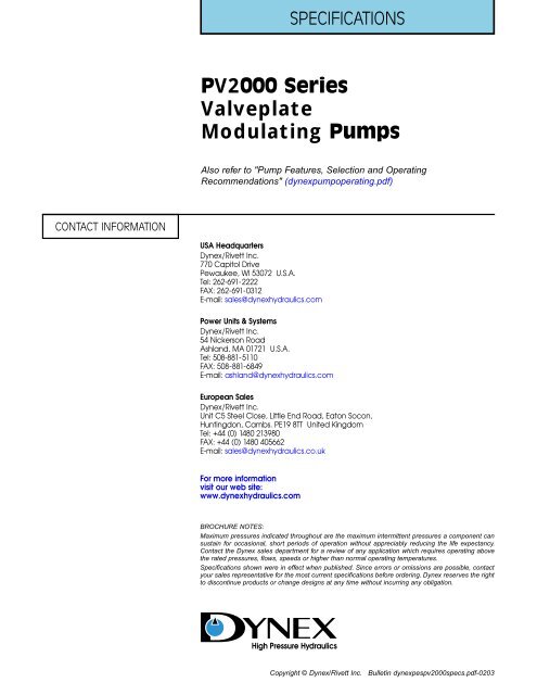
SPECIFICATIONS<br />
<strong>PV2000</strong> <strong>Series</strong><br />
Valveplate<br />
Modulating <strong>Pumps</strong><br />
Also refer to "Pump Features, Selection and Operating<br />
Recommendations" (dynexpumpoperating.<strong>pdf</strong>)<br />
CONTACT INFORMATION<br />
USA Headquarters<br />
Dynex/Rivett Inc.<br />
770 Capitol Drive<br />
Pewaukee, WI 53072 U.S.A.<br />
Tel: 262-691-2222<br />
FAX: 262-691-0312<br />
E-mail: sales@dynexhydraulics.com<br />
Power Units & Systems<br />
Dynex/Rivett Inc.<br />
54 Nickerson Road<br />
Ashland, MA 01721 U.S.A.<br />
Tel: 508-881-5110<br />
FAX: 508-881-6849<br />
E-mail: ashland@dynexhydraulics.com<br />
European Sales<br />
Dynex/Rivett Inc.<br />
Unit C5 Steel Close, Little End Road, Eaton Socon,<br />
Huntingdon, Cambs. PE19 8TT United Kingdom<br />
Tel: +44 (0) 1480 213980<br />
FAX: +44 (0) 1480 405662<br />
E-mail: sales@dynexhydraulics.co.uk<br />
For more information<br />
visit our web site:<br />
www.dynexhydraulics.com<br />
BROCHURE NOTES:<br />
Maximum pressures indicated throughout are the maximum intermittent pressures a component can<br />
sustain for occasional, short periods of operation without appreciably reducing the life expectancy.<br />
Contact the Dynex sales department for a review of any application which requires operating above<br />
the rated pressures, flows, speeds or higher than normal operating temperatures.<br />
Specifications shown were in effect when published. Since errors or omissions are possible, contact<br />
your sales representative for the most current specifications before ordering. Dynex reserves the right<br />
to discontinue products or change designs at any time without incurring any obligation.<br />
DYNEX<br />
High Pressure Hydraulics<br />
Copyright © Dynex/Rivett Inc. Bulletin dynexpespv2000specs.<strong>pdf</strong>-0203
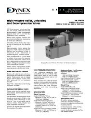
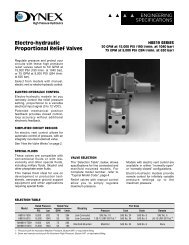
VALVEPLATE PUMPS & MOTORS<br />
Electro-Hydraulic <strong>Pumps</strong> and Motors<br />
For Accurate, Remote Speed Control<br />
Dynex valveplate pumps and motors<br />
are used in demanding applications<br />
requiring accurate control, and<br />
resistance to dust, dirt, vibration and<br />
difficult duty cycles.<br />
<strong>PV2000</strong> SERIES PUMPS – These<br />
pumps provide a perfect combination<br />
of accurate electro-hydraulic control,<br />
long service life and high efficiency<br />
operation.<br />
On electro-hydraulic modulating<br />
models, output flow is proportional to<br />
a variable electrical input signal.<br />
Other models are available with<br />
pressure compensation, remote controlled<br />
compensation, load sensing<br />
and economical on/off control.<br />
MF2000 AND MV2000 MOTORS –<br />
These motors produce high torque<br />
relative to their compact size. The<br />
largest weighs 38 lb (17,2 kg) and<br />
produces up to 62 hp at 3000 psi<br />
(46 kW at 210 bar).<br />
Variable models provide two speeds.<br />
A solenoid valve de-strokes the<br />
motor to its lower displacement,<br />
providing increased speed.<br />
MF5000 SERIES MOTORS – Heavyduty<br />
motors produce steady power<br />
with smooth speed variation.<br />
They keep operating even when<br />
subjected to extreme pressure<br />
spikes, severe vibration and tough<br />
duty cycles. They are ideal for<br />
systems with constant starting and<br />
stopping, and sudden direction<br />
reversals.<br />
For information on motors refer to<br />
dynexpesmfmvspecs.<strong>pdf</strong><br />
CONTAMINATION<br />
TOLERANT BARREL<br />
Special anti-galling coating<br />
provides long service life<br />
ENERGY-SAVING CONTROLS<br />
Pressure compensation and load sensing<br />
match system requirements<br />
S.A.E. NO. 20 INLET PORT<br />
Improves filling for good<br />
performance with cold<br />
fluids and high speeds<br />
MECHANICAL POSITION FEEDBACK<br />
Patented control precisely monitors<br />
and controls cradle angle<br />
ELECTRO-HYDRAULIC CONTROL<br />
Modulating models deliver flow<br />
proportional to variable input signal<br />
PV2 <strong>Series</strong> Electro-hydraulic Modulating Pump<br />
2
<strong>PV2000</strong> SERIES PUMPS<br />
Reliable Modulating<br />
<strong>Pumps</strong> For Long,<br />
Difficult Duty Cycles<br />
<strong>PV2000</strong> <strong>Series</strong> pumps, with their<br />
durable construction yet simple<br />
electro-hydraulic design, provide<br />
long, reliable service life.<br />
Modulating pumps, with accurate<br />
output, feature a patented design<br />
requiring no additional electronic feedback.<br />
The rugged design provides<br />
dependable operation in adverse<br />
conditions including extreme heat, dirty<br />
environments and difficult duty cycles.<br />
ACCURATE FLOW CONTROL<br />
Electro-hydraulic modulating models<br />
deliver flow proportional to an<br />
electrical input signal.<br />
Patented mechanical position<br />
feedback continuously monitors and<br />
adjusts pump output during operation.<br />
A mechanical linkage between cradle<br />
position and the force motor provides<br />
accurate control of pump output.The<br />
result is closed control-loop accuracy<br />
without additional electronic feedback.<br />
Machines can use position sensors<br />
or micro-processor input for automatic<br />
control; or functions can be<br />
controlled with manual input.<br />
Components can be located where<br />
it’s most convenient, with hydraulics<br />
remotely controlled by the operator.<br />
LONG SERVICE LIFE<br />
These pumps operate reliably in<br />
harsh operating conditions. Piston<br />
barrels treated with a special antigalling<br />
coating provide superior<br />
contamination tolerance.<br />
Internal shafts with 1 inch (25,4 mm)<br />
diameters and extra large inlet ports,<br />
for improved filling characteristics,<br />
enable these pumps to keep running<br />
under adverse conditions.<br />
PUMP CONTROL OPTIONS<br />
<strong>PV2000</strong> <strong>Series</strong> pumps are available<br />
in three displacements, with a choice<br />
of controls:<br />
Pressure Compensation<br />
Maintains a preset maximum pressure,<br />
adjustable from 500 to 3500 psi (35 to<br />
245 bar). These models include an<br />
integral stroke limiter for convenient<br />
adjustment of maximum pump output.<br />
Remote Compensator<br />
Offers the convenience of remotely<br />
regulating maximum pressure from<br />
the operator’s station.<br />
Load Sensing<br />
Automatically provides the output<br />
required by the function at a pressure<br />
150 to 300 psi (10,4 to 20,7 bar)<br />
higher than load pressure.<br />
On/Off Control<br />
Brings pump on-stroke and off-stroke<br />
in response to an electrical signal.<br />
On/off models come with standard<br />
pressure compensator. Maximum<br />
output can be set using an integral<br />
stroke limiter control.<br />
Modulating Control<br />
Delivers flow proportional to a variable<br />
electrical input signal. Modulating<br />
pumps come with standard pressure<br />
compensator override.<br />
PUMP SPECIFICATIONS<br />
Output at 1800 rpm, 3000 psi<br />
(210 bar)<br />
Model PV2024:<br />
17.7 U.S. gpm (67,0 L/min);<br />
Model PV2029:<br />
21.5 U.S. gpm (81,4 L/min);<br />
Model PV2032:<br />
24.5 U.S. gpm (92,7 L/min)<br />
See “Typical Performance Curves”<br />
on page 8 for maximum output.<br />
<strong>PV2000</strong> <strong>Series</strong> Pump<br />
With Electro-hydraulic<br />
Modulating Control<br />
Rated Pressure<br />
Rated: 3000 psi (210 bar);<br />
Maximum Intermittent: 4000 psi<br />
(280 bar). Note that adjustment of the<br />
compensator is limited to 3500 psi<br />
(245 bar) maximum. For intermittent<br />
operation above 3500 psi (245 bar)<br />
contact the Dynex sales department.<br />
Rated Speed<br />
All Models: 2000 rpm<br />
Maximum Speed<br />
Models PV2024, PV2029: 2800 rpm;<br />
Model PV2032: 2600 rpm<br />
Required External Pilot Supply<br />
(Electro-Hydraulic Models)<br />
Pressure: 200 psi (13,8 bar);<br />
Flow: 0.2 gpm (0,8 L/min)<br />
FORCE MOTOR ELECTRICAL DATA<br />
Description<br />
Rated voltage<br />
Full Stroke Voltage<br />
Rated Input Current<br />
Resistance<br />
Wattage<br />
Inductance at 1.0 kHz<br />
Recommended<br />
Dither Signal ➁<br />
Specifications ➀<br />
± 12 V (D.C.)<br />
± 9 V (D.C.)<br />
490 mA<br />
24.5 Ohms<br />
5.9 Watts<br />
60 mH<br />
± 3 V (D.C.) 60 Hz<br />
Square Wave<br />
➀ Specifications at 70° F (21° C)<br />
➁ A dither signal is recommended to improve<br />
response time and reduce hysteresis. A pulse<br />
width modulation signal can also be used to<br />
improve performance.<br />
3
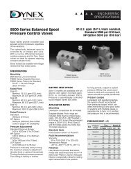
PV2 SERIES PUMP OPERATION<br />
Electro-Hydraulic<br />
Pump Operation<br />
ACCURATE OUTPUT FLOW<br />
Modulating models deliver flow proportional<br />
to a variable electrical<br />
signal supplied to a force motor in the<br />
pilot-stage. The force motor is an<br />
BIASED<br />
OFF-STROKE<br />
REGULATED<br />
ON-STROKE<br />
Cradle movement in modulating pumps is<br />
controlled by a variable electrical signal<br />
supplied to the pilot-stage force motor.<br />
electro-magnetic device with an<br />
armature that moves in response to<br />
the magnitude of the electrical<br />
signal.<br />
The armature controls the movement<br />
of a pilot spool which ports pilot flow to<br />
the pump control piston. An external<br />
pilot supply of 0.2 gpm at 200 psi<br />
(0,8 L/min at 13,8 bar) is required.<br />
The pump cradle in these models is<br />
biased to an off-stroke position. The<br />
control piston moves to bring the pump<br />
on-stroke, in response to the electrical<br />
signal supplied to the force motor.<br />
As the electrical signal is increased,<br />
pump output is proportionally<br />
increased, up to full flow. Reducing the<br />
signal decreases pump output.<br />
For any applied electrical signal,<br />
there is a distinct position for the<br />
cradle. Pressure to the control piston<br />
is automatically regulated to maintain<br />
the commanded cradle position.<br />
FLOW (%)<br />
100<br />
75<br />
50<br />
25<br />
0<br />
OFF-STROKE<br />
VOLTAGE<br />
DEADBAND<br />
COUNTER-CLOCKWISE<br />
ADJUSTMENT<br />
CLOCKWISE<br />
ADJUSTMENT<br />
START<br />
HYSTERESIS<br />
FULL-STROKE<br />
VOLTAGE<br />
Pump output can be illustrated by a “flow<br />
versus current” curve. Deadband, or the<br />
amount of signal required to initiate flow,<br />
can be adjusted by rotating the force motor.<br />
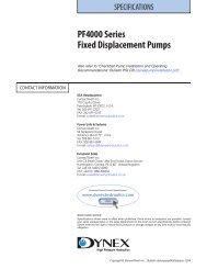
MECHANICAL POSITION FEEDBACK<br />
Cradle angle, and resulting pump<br />
output, is accurately monitored and<br />
controlled by patented mechanical<br />
position feedback. See the drawings<br />
below for a description of how this<br />
design operates.<br />
FIGURE 1: The mechanical position feedback design consists<br />
of a feedback rod (attached to the control piston) and a pilot<br />
sleeve which rides on a feedback cam in the rod. A hole in the<br />
sleeve, in conjunction with the land on the spool, forms a<br />
control orifice. When no flow is required this orifice is closed.<br />
FIGURE 2: In response to the electrical signal, the force motor<br />
armature retracts. The pilot spool, held in contact with the<br />
armature, moves inside the sleeve directing pilot flow to the<br />
control piston through the now open orifice. Movement of the<br />
piston changes the cradle angle and brings the pump on-stroke.<br />
FIGURE 3: The feedback rod moves with the control piston.<br />
When the cradle has reached its proper angle, movement of<br />
the feedback cam causes the sleeve to shift in relation to the<br />
spool. This closes the orifice and effectively nulls the pilot<br />
stage. The control piston and the cradle remain in this position<br />
as long as the electrical signal is unchanged.<br />
FORCE MOTOR ARMATURE<br />
PILOT SPOOL<br />
PILOT SLEEVE<br />
CONTROL ORIFICE CLOSED<br />
Figure 1: Cradle biased off-stroke<br />
PILOT FLOW<br />
FEEDBACK ROD<br />
CONTROL PISTON<br />
SPOOL SHIFTS TO OPEN<br />
CONTROL ORIFICE<br />
SLEEVE SHIFTS TO CLOSE<br />
CONTROL ORIFICE<br />
FEEDBACK CAM<br />
Figure 2: Pilot flow ported through control orifice<br />
Figure 3: Movement of sleeve nulls pilot stage<br />
4
<strong>PV2000</strong> SERIES PUMPS<br />
Pump Type<br />
Variable displacement valveplate<br />
design with a choice of controls to<br />
regulate delivery.<br />
Mounting<br />
S.A.E. B 2-bolt pattern<br />
Shaft Data<br />
Standard, S.A.E. B-B 1.00 inch<br />
keyed shaft,<br />
or S.A.E. B-B spline shaft:<br />
1.000/.978 inch diameter standard<br />
S.A.E. 15 tooth, 16/32 D.P. 30°<br />
involute spline;<br />
Optional S.A.E. B Spline Shaft:<br />
.875/.853 inch diameter standard<br />
S.A.E. 13 tooth, 16/32 D.P. 30°<br />
involute spline.<br />
Weight (Mass)<br />
Compensated: 56 lb (25,4 kg);<br />
On/Off: 59 lb (26,8 kg);<br />
Modulating: 64 lb (29,0 kg);<br />
Thru-Shaft: 75 lb (34,0 kg)<br />
SELECTING PV2 SERIES PUMPS<br />
The table below indicates which<br />
controls are available for each pump<br />
size.<br />
STANDARD PUMPS – Control options<br />
are shown for models with both<br />
rotations (as viewed from shaft-end).<br />
Model numbers listed are for pumps<br />
with standard S.A.E. B-B 1.00 inch<br />
keyed shafts or standard S.A.E. B-B<br />
spline shafts. For pumps with optional<br />
S.A.E. B spline shaft contact your<br />
Dynex representative for specific<br />
model numbers.<br />
THRU-SHAFT PUMPS – Thru-shaft<br />
models can reduce circuit costs by<br />
eliminating separate drives, saving<br />
space and reducing installation time.<br />
These models are available in a<br />
tandem configuration or as a single<br />
thru-shaft pump. Any accessory<br />
Tandem Thru-Shaft <strong>PV2000</strong> <strong>Series</strong> <strong>Pumps</strong><br />
pump, with a standard S.A.E. B 2-bolt<br />
pattern, can be mounted “piggy-back”.<br />
The internal coupling is a standard<br />
S.A.E. B-B spline.<br />
Thru-shaft pumps are available with a<br />
choice of control options. For<br />
installation details and complete<br />
model numbers, contact the Dynex<br />
sales department.<br />
MODEL SELECTION<br />
17.7 U.S. gpm<br />
(67,0 L/min)<br />
at 1800 rpm<br />
Clockwise Rotation<br />
21.5 U.S. gpm<br />
(81,4 L/min)<br />
at 1800 rpm<br />
24.5 U.S. gpm<br />
(92,7 L/min)<br />
at 1800 rpm<br />
17.7 U.S. gpm<br />
(67,0 L/min)<br />
at 1800 rpm<br />
Counter-Clockwise Rotation<br />
21.5 U.S. gpm<br />
(81,4 L/min)<br />
at 1800 rpm<br />
24.5 U.S. gpm<br />
(92,7 L/min)<br />
at 1800 rpm<br />
Shaft<br />
(S.A.E. B-B)<br />
Pump Control<br />
Description<br />
PV2024-3084 PV2029-3024 PV2032-3147 PV2024-3086 PV2029-3025 PV2032-3148 Keyed<br />
PV2024-3085 PV2029-3026 PV2032-3149 PV2024-3087 PV2029-3027 PV2032-3150 Spline<br />
Pressure Compensated ➀<br />
PV2024-3088 PV2029-3028 PV2032-3151 PV2024-3089 PV2029-3029 PV2032-3152 Keyed Remote<br />
PV2024-3067 PV2029-3030 PV2032-3153 PV2024-3090 PV2029-3031 PV2032-3154 Spline Pressure Compensated ➀<br />
PV2024-2950 PV2029-3032 PV2032-3155 PV2024-3082 PV2029-3033 PV2032-3156 Keyed<br />
PV2024-2951 PV2029-3034 PV2032-3157 PV2024-3083 PV2029-3035 PV2032-3158 Spline<br />
Load Sensing ➁<br />
PV2024-3095 PV2029-3038 — PV2024-3097 PV2029-3039 — Keyed<br />
PV2024-3096 PV2029-3099 — PV2024-3098 PV2029-3100 — Spline<br />
On/Off Control ➁<br />
PV2024-3091 PV2029-3036 — PV2024-3092 PV2029-3037 — Keyed<br />
PV2024-3073 PV2029-3093 — PV2024-3074 PV2029-3094 — Spline<br />
Modulating Control ➁<br />
➀ Pressure compensator setting adjustable from 500 to 3000 psi (35 to 210 bar).<br />
➁ Models listed here also have pressure compensator override.<br />
8.00<br />
(203,2)<br />
DIRECTION OF ROTATION<br />
VIEWED FROM SHAFT END<br />
1.19<br />
(30,2)<br />
5.750<br />
(146,05)<br />
1.19<br />
(30,2)<br />
3.81<br />
(96,8)<br />
7.63<br />
(193,8)<br />
SQUARE KEY<br />
.25 x 1.00 (6,4 x 25,4)<br />
4.000<br />
3.998<br />
1.111<br />
1.101<br />
1.000<br />
.998<br />
( )<br />
101,60<br />
101,55<br />
( )<br />
28,22<br />
27,97<br />
( )<br />
25,40<br />
25,35<br />
.562 (14,27)<br />
2 MTG. HOLES<br />
ALTERNATE<br />
DRAIN PORT<br />
NO. 8 S.A.E.<br />
1.81<br />
(46,0)<br />
1.63<br />
(41,4) DRAIN PORT<br />
NO. 8 S.A.E.<br />
.59<br />
(15,0)<br />
.375<br />
(9,52)<br />
8.83<br />
(224,3)<br />
2.56<br />
(65,0)<br />
7.78<br />
(197,6)<br />
9.71<br />
(246,6)<br />
10.92<br />
(323,4)<br />
3.12<br />
(79,2)<br />
OUTLET PORT<br />
NO. 16 S.A.E.<br />
1.625<br />
(41,28)<br />
ALTERNATE<br />
DRAIN PORT<br />
NO. 6 S.A.E.<br />
2.81<br />
(71,4)<br />
5.32<br />
(135,1)<br />
INLET PORT<br />
NO. 20 S.A.E.<br />
1.625<br />
(41,28)<br />
4.06<br />
(103,1)<br />
4.00<br />
(101,6)<br />
DIRECTION<br />
OF ROTATION<br />
VIEWED FROM<br />
PORT END<br />
.25 (6,4)<br />
ADJUSTMENT<br />
Pressure Compensated Model (With Stroke Limiter)<br />
5
<strong>PV2000</strong> SERIES PUMPS<br />
Installation and<br />
Performance Data<br />
.25 (6,4) INT. HEX<br />
(ADJUSTMENT<br />
FOR CRADLE STOP)<br />
Refer to the installation drawing on<br />
page 6 for dimensions common to<br />
all models.<br />
Standard Seals<br />
Buna-N (Nitrile)<br />
Fluid<br />
High-grade premium petroleum-based<br />
oil, with a combination of anti-wear,<br />
demulsibility, rust protection, and<br />
oxidation resistance and foam resistance<br />
properties.<br />
Minimum Filtration Levels<br />
Pump inlet, 25 µ nominal;<br />
Pressure or return line, 25 µ nominal;<br />
Pilot supply (electro-hydraulic<br />
models), 10 µ nominal.<br />
While finer filtration levels than these<br />
are desirable, restricting flow to the<br />
pump inlet must be avoided.<br />
Inlet Conditions (Minimum)<br />
0 psig (0 bar) to 1800 rpm;<br />
5 psig (0,35 bar) to 2800 rpm.<br />
Mounting<br />
Generally, mount pumps with shaft<br />
horizontal and either drain port<br />
vertically up. Consult your sales<br />
representative for other orientations.<br />
Shaft Loading<br />
Consult your Dynex sales representative<br />
for applications which require<br />
sideloading.<br />
Start-up<br />
Fill pump through upper-most case<br />
drain prior to start-up. It may be<br />
necessary to bleed air from pump<br />
outlet for initial priming.<br />
7.78<br />
1.63<br />
(197,6)<br />
(41,4)<br />
10.92<br />
(277,4) MAX.<br />
7.78<br />
(197,6)<br />
10.92<br />
MAX.<br />
(277,4)<br />
9.08<br />
(230,6)<br />
10.84<br />
(275,3)<br />
1.63<br />
(41,4)<br />
REMOTE<br />
PRESSURE PORT<br />
NO. 4 S.A.E.<br />
.25 (6,4) INT. HEX<br />
(ADJUSTMENT<br />
FOR CRADLE<br />
STOP)<br />
PILOT SUPPLY PORT<br />
NO. 4 S.A.E.<br />
PRESSURE<br />
COMPENSATOR<br />
2.00<br />
(50,8)<br />
Load Sensing Model (With Stroke Limiter)<br />
1.19<br />
(30,2)<br />
Remote Pressure Compensated Model (With Stroke Limiter)<br />
2.81<br />
(71,4)<br />
LOAD SENSING CONTROL PORT<br />
NO. 4 S.A.E.<br />
3.88<br />
(98,6)<br />
2.93<br />
(74,4)<br />
3.21<br />
(81,5)<br />
4.06<br />
(103,1)<br />
2.72<br />
(69,1)<br />
4.50<br />
(114,3)<br />
5.38<br />
(136,7)<br />
2.81<br />
(71,4)<br />
2.81<br />
(71,4)<br />
.25 (6,4)<br />
ADJUSTMENT<br />
.30<br />
MINIMUM<br />
(7,6)<br />
.25 (6,4)<br />
MALE SPADE<br />
TERMINALS (2)<br />
FLUID SPECIFICATIONS ➀<br />
Specification<br />
Viscosity at<br />
100° F .<br />
(37,8° C)<br />
Fluid Grade<br />
Summer ➁ Winter ➂<br />
150-300 SUS 75-200 SUS<br />
(38,3-64,9 cSt) (14,4-43,1 cSt)<br />
Viscosity at 43 SUS 43 SUS<br />
210° F (5,2 cSt) (5,2 cSt)<br />
(98,9° C) Minimum Minimum<br />
Pour Point, 0° F<br />
-40° F<br />
(-40° C)<br />
Typical (-17,8° C)<br />
or Less<br />
Viscosity 95 95<br />
Index Minimum Minimum<br />
➀ If fluid conditions fall outside of the range<br />
shown, consult the Dynex sales department.<br />
➁ Warm Weather Grade, Above +40° F (4,4° C)<br />
➂ Cold Weather Grade, Below +40° F (4,4° C)<br />
Modulating Model (With Pressure Compensator)<br />
.25 (6,4) MALE SPADE TERMINALS (2)<br />
11.05<br />
MAX.<br />
(280,7)<br />
.25 (6,4) INT. HEX<br />
(ADJUSTMENT<br />
FOR CRADLE STOP)<br />
2.26<br />
(57,4)<br />
5.05<br />
(128,3)<br />
PRESSURE COMPENSATOR<br />
On/Off Model (With Pressure Compensator and Stroke Limiter)<br />
PILOT SUPPLY PORT<br />
NO. 4 S.A.E.<br />
3.19<br />
(81,0)<br />
6
<strong>PV2000</strong> SERIES PUMPS<br />
TYPICAL PERFORMANCE CURVES (AT 1800 RPM)<br />
KW<br />
HP<br />
PV2024<br />
PV2029<br />
PV2032<br />
50<br />
60<br />
INPUT POWER<br />
40<br />
30<br />
20<br />
50<br />
40<br />
30<br />
20<br />
INPUT POWER (FULL STROKE)<br />
INPUT POWER (FULL STROKE)<br />
INPUT POWER (FULL STROKE)<br />
10<br />
0<br />
10<br />
0<br />
INPUT POWER (COMPENSATED)<br />
INPUT POWER (COMPENSATED)<br />
INPUT POWER (COMPENSATED)<br />
N • M<br />
LB • IN<br />
250<br />
2250<br />
2000<br />
INPUT TORQUE<br />
200<br />
150<br />
100<br />
1750<br />
1500<br />
1250<br />
1000<br />
750<br />
INPUT TORQUE (FULL STROKE)<br />
INPUT TORQUE (FULL STROKE)<br />
INPUT TORQUE (FULL STROKE)<br />
50<br />
500<br />
250<br />
0<br />
0<br />
L/MIN.<br />
U.S.<br />
GPM<br />
DELIVERY<br />
100<br />
90<br />
80<br />
70<br />
60<br />
50<br />
40<br />
30<br />
24<br />
20<br />
16<br />
12<br />
8<br />
COMPENSATOR<br />
SETTING<br />
AT 1500 PSI<br />
105 BAR<br />
DELIVERY AT 1800 RPM<br />
AT 2500 PSI<br />
175 BAR<br />
COMPENSATOR<br />
SETTING<br />
AT 1500 PSI<br />
105 BAR<br />
DELIVERY AT 1800 RPM<br />
AT 2500 PSI<br />
175 BAR<br />
COMPENSATOR<br />
SETTING<br />
AT 1500 PSI<br />
105 BAR<br />
DELIVERY AT 1800 RPM<br />
AT 2500 PSI<br />
175 BAR<br />
20<br />
10<br />
4<br />
0<br />
0<br />
100<br />
90<br />
80<br />
VOLUMETRIC EFFICIENCY<br />
OVERALL EFFICIENCY<br />
VOLUMETRIC EFFICIENCY<br />
OVERALL EFFICIENCY<br />
VOLUMETRIC EFFICIENCY<br />
OVERALL EFFICIENCY<br />
EFFICIENCY – %<br />
70<br />
60<br />
50<br />
40<br />
30<br />
20<br />
10<br />
0<br />
PSI<br />
1000 2000 3000 4000<br />
PSI<br />
1000 2000 3000 4000<br />
PSI<br />
1000 2000 3000 4000<br />
BAR<br />
50<br />
100 150 200 250<br />
OUTPUT PRESSURE<br />
BAR<br />
50<br />
100 150 200 250<br />
OUTPUT PRESSURE<br />
BAR<br />
50<br />
100 150 200 250<br />
OUTPUT PRESSURE<br />
7