
You also want an ePaper? Increase the reach of your titles
YUMPU automatically turns print PDFs into web optimized ePapers that Google loves.
<strong>AF</strong><br />
7-96<br />
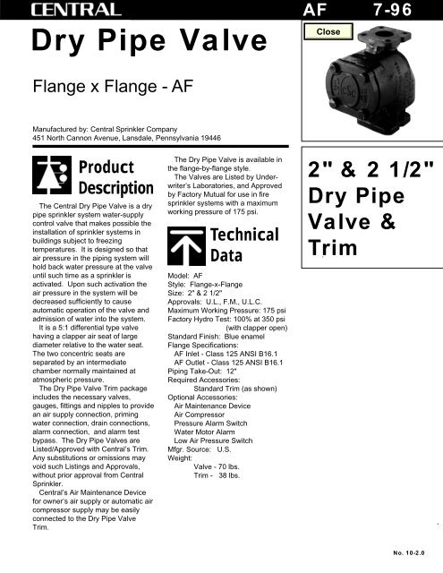
<strong>Dry</strong> <strong>Pipe</strong> <strong>Valve</strong><br />
Flange x Flange - <strong>AF</strong><br />
Manufactured by: Central Sprinkler Company<br />
451 North Cannon Avenue, Lansdale, Pennsylvania 19446<br />
Product<br />
Description<br />
The Central <strong>Dry</strong> <strong>Pipe</strong> <strong>Valve</strong> is a dry<br />
pipe sprinkler system water-supply<br />
control valve that makes possible the<br />
installation of sprinkler systems in<br />
buildings subject to freezing<br />
temperatures. It is designed so that<br />
air pressure in the piping system will<br />
hold back water pressure at the valve<br />
until such time as a sprinkler is<br />
activated. Upon such activation the<br />
air pressure in the system will be<br />
decreased sufficiently to cause<br />
automatic operation of the valve and<br />
admission of water into the system.<br />
It is a 5:1 differential type valve<br />
having a clapper air seat of large<br />
diameter relative to the water seat.<br />
The two concentric seats are<br />
separated by an intermediate<br />
chamber normally maintained at<br />
atmospheric pressure.<br />
The <strong>Dry</strong> <strong>Pipe</strong> <strong>Valve</strong> Trim package<br />
includes the necessary valves,<br />
gauges, fittings and nipples to provide<br />
an air supply connection, priming<br />
water connection, drain connections,<br />
alarm connection, and alarm test<br />
bypass. The <strong>Dry</strong> <strong>Pipe</strong> <strong>Valve</strong>s are<br />
Listed/Approved with Central’s Trim.<br />
Any substitutions or omissions may<br />
void such Listings and Approvals,<br />
without prior approval from Central<br />
Sprinkler.<br />
Central’s Air Maintenance Device<br />
for owner’s air supply or automatic air<br />
compressor supply may be easily<br />
connected to the <strong>Dry</strong> <strong>Pipe</strong> <strong>Valve</strong><br />
Trim.<br />
The <strong>Dry</strong> <strong>Pipe</strong> <strong>Valve</strong> is available in<br />
the flange-by-flange style.<br />
The <strong>Valve</strong>s are Listed by Underwriter’s<br />
Laboratories, and Approved<br />
by Factory Mutual for use in fire<br />
sprinkler systems with a maximum<br />
working pressure of 175 psi.<br />
Technical<br />
Data<br />
Model: <strong>AF</strong><br />
Style: Flange-x-Flange<br />
Size: 2" & 2 1/2"<br />
Approvals: U.L., F.M., U.L.C.<br />
Maximum Working Pressure: 175 psi<br />
Factory Hydro Test: 100% at 350 psi<br />
(with clapper open)<br />
Standard Finish: Blue enamel<br />
Flange Specifications:<br />
<strong>AF</strong> Inlet - Class 125 ANSI B16.1<br />
<strong>AF</strong> Outlet - Class 125 ANSI B16.1<br />
Piping Take-Out: 12"<br />
Required Accessories:<br />
Standard Trim (as shown)<br />
Optional Accessories:<br />
Air Maintenance Device<br />
Air Compressor<br />
Pressure Alarm Switch<br />
Water Motor Alarm<br />
Low Air Pressure Switch<br />
Mfgr. Source: U.S.<br />
Weight:<br />
<strong>Valve</strong> - 70 lbs.<br />
Trim - 38 lbs.<br />
2" & 2 1/2"<br />
<strong>Dry</strong> <strong>Pipe</strong><br />
<strong>Valve</strong> &<br />
Trim<br />
No. 10-2.0
Figure 1<br />
<strong>Dry</strong> <strong>Pipe</strong> <strong>Valve</strong> Section<br />
Flanged Outlet - Model <strong>AF</strong><br />
1<br />
9<br />
Air Supply Connection<br />
(3/4" NPT)<br />
10<br />
Priming Connection<br />
(3/4" NPT)<br />
7<br />
8<br />
12"<br />
2<br />
3<br />
Inter. Chamber<br />
Connection<br />
(3/4" NPT)<br />
2"<br />
5<br />
6<br />
4<br />
4 1/16"<br />
Main Drain Connection<br />
1 1/4" NPT<br />
Note: The Clapper Assembly may be removed from the body of the <strong>Dry</strong> <strong>Pipe</strong> <strong>Valve</strong><br />
by removing the two 3/8" plugs (#6) and removing the hinge pin (#5).<br />
Parts List - <strong>Dry</strong> <strong>Pipe</strong> <strong>Valve</strong><br />
Model <strong>AF</strong> (2" Part No. 2210), (2 1/2" Part No. 2212)<br />
Identification Number Part Number<br />
Number Required Description (2" & 2 1/2" Size)<br />
1 1 Body (2") 200-188-00<br />
1 1 Body (2 1/2") 200-188-04<br />
2 1 Water Seat Ring* 200-183-00<br />
3 1 Air Seat Ring* 200-184-00<br />
4 2 Body Bushing 300-187-00<br />
5 1 Hinge Pin 818-10-100<br />
6 2 <strong>Pipe</strong> Plug, 3/8"-18 NPT 818-12-000<br />
7 1 Clapper Assembly 200-186-00<br />
8 1 Cover 250-02-000<br />
9 1 Cover Gasket 250-04-000<br />
10 4 Cover Bolt 3/4"-10 x 2" Long 600-03-000<br />
*Not field replaceable.<br />
2
Figure 2<br />
<strong>Dry</strong> <strong>Pipe</strong> <strong>Valve</strong> Clapper Assembly<br />
Latch<br />
Pin<br />
8<br />
Retaining<br />
Ring<br />
9<br />
6<br />
Clapper<br />
Bushing<br />
10<br />
Latch<br />
Spring<br />
1<br />
Clapper<br />
2<br />
Clapper<br />
Bushing<br />
7<br />
Latch<br />
5<br />
Bolt<br />
4<br />
Retaining<br />
Plate<br />
3<br />
Rubber<br />
Seal<br />
Parts List - Clapper Assembly<br />
Model <strong>AF</strong> (2" & 2 1/2" Assembly No. 200-186-000)<br />
Identification Number Part Number<br />
Number Required Description (2" & 2 1/2" Size)<br />
1 1 Clapper 200-182-00<br />
2 2 Clapper Bushing (thru body) 818-08-000<br />
3 1 Rubber Seal 200-180-00<br />
4 1 Retaining Plate 200-181-00<br />
5 4 1/4"-20 x 5/8" Hex Head Bolts 300-16-000<br />
6 2 Clapper Bushing (thru latch) 818-08-000<br />
7 1 Latch 300-10-000<br />
8 1 Latch Pin 300-23-000<br />
9 2 Retaining Ring 300-22-000<br />
10 1 Latch Spring 300-21-000<br />
3
Operation<br />
When the <strong>Dry</strong> <strong>Pipe</strong> <strong>Valve</strong> is in the<br />
set position, the rubber-faced clapper<br />
is tightly closed on two concentric<br />
seat rings. The inner ring is the water<br />
ring and the outer ring is the air ring.<br />
The annular space between the two<br />
seat rings (intermediate chamber) is<br />
open to the atmosphere via the alarm<br />
connection trim piping to the normally<br />
open automatic ball drip valve.<br />
Priming water is provided above the<br />
clapper up to the level of the priming<br />
connection. Above the priming water,<br />
compressed air (or nitrogen) is<br />
maintained at a pressure sufficient to<br />
hold the clapper closed. The <strong>Dry</strong><br />
<strong>Pipe</strong> <strong>Valve</strong> has a differential trip ratio<br />
of approximately 5 to 1. Thus the<br />
valve will open (trip) when the air<br />
pressure in the system piping is<br />
reduced to approximately one-fifth of<br />
the water supply pressure.<br />
The purpose of the priming water is<br />
to assist in providing a positive seal at<br />
the air seat ring to prevent air from<br />
escaping into the intermediate<br />
chamber and on to the atmosphere.<br />
The clapper will remain in the closed<br />
position as long as the air pressure in<br />
the piping system is maintained at the<br />
proper level.<br />
When a sprinkler operates, the air<br />
pressure in the piping system decays<br />
due to the air escaping from the<br />
opened sprinkler. When the air<br />
pressure has decayed to the point<br />
that it is no longer adequate to hold<br />
the clapper shut, the water supply<br />
pressure lifts the clapper which<br />
automatically latches in the open<br />
position. Water flows into the system<br />
piping to the open sprinkler(s). At the<br />
same time, water flows via the<br />
intermediate chamber into the alarm<br />
connection trim piping (closing the<br />
automatic ball drip valve) and<br />
continues on through the alarm line to<br />
operate the pressure actuated alarm<br />
switch and/or the water motor alarm.<br />
When a sprinkler opens, the<br />
resulting air pressure decay is<br />
inversely proportional to the volume<br />
of air in the sprinkler piping.<br />
Design<br />
Data<br />
DESIGN CONSIDERATIONS<br />
General<br />
The Central Model <strong>AF</strong> <strong>Dry</strong> <strong>Pipe</strong><br />
<strong>Valve</strong>s must be installed in the<br />
vertical position. They should be<br />
located in a sprinklered area not<br />
subject to freezing conditions, such<br />
as a well-lighted and heated valve<br />
house or similar enclosure having<br />
sufficient room to enable ease of<br />
installation, care and maintenance.<br />
When properly installed, the Trim<br />
on the <strong>Dry</strong> <strong>Pipe</strong> <strong>Valve</strong> protrudes the<br />
following horizontal distances from<br />
the center line (C.L.) of the riser:<br />
Trim 2" & 2 1/2"<br />
Protrusion* <strong>Valve</strong><br />
C.L. to left 11 1/2"<br />
C.L. to right 15"<br />
C.L. to rear 11 1/2"<br />
* When the observer is facing<br />
the valve body cover plate.<br />
Drawings<br />
The dry pipe system working<br />
drawings must show:<br />
1. The manufacturer, style, model<br />
number, and size of the <strong>Dry</strong><br />
<strong>Pipe</strong> <strong>Valve</strong>.<br />
2. The total number of sprinklers<br />
on each dry pipe system, and,<br />
3. The capacity (gallons) of each<br />
dry pipe system.<br />
Pendent sprinklers in dry pipe<br />
systems must be of the dry pendent<br />
type in areas that are subject to<br />
freezing.<br />
<strong>Dry</strong> pipe systems that supply<br />
freezer areas must be equipped with<br />
a local, Low Air Pressure Alarm which<br />
may be connected to the system riser<br />
just above the <strong>Dry</strong> <strong>Pipe</strong> <strong>Valve</strong>. For<br />
“freezer area” systems, a desiccant<br />
air dryer should be provided in the air<br />
supply line to remove moisture from<br />
the compressed air.<br />
4<br />
<strong>Dry</strong> System Capacity<br />
The capacity (gallons) of the piping<br />
system may be calculated using the<br />
following table:<br />
Capacity (gal./ft.)<br />
Diameter<br />
(in.) Sch. 40 Sch. 10<br />
3/4 .028 —<br />
1 .045 .049<br />
1 1/4 .078 .085<br />
1 1/2 .106 .115<br />
2 .174 .190<br />
2 1/2 .248 .283<br />
3 .383 .433<br />
4 .660 .740<br />
6 1.50 1 1.649 1<br />
8 2.66 3 2.776 2<br />
1<br />
0.134" wall pipe<br />
2<br />
0.188" wall pipe<br />
3<br />
Schedule 30 pipe<br />
In accordance with current NFPA<br />
13, the maximum allowable capacity<br />
of a single dry pipe system is<br />
normally 750 gallons. The capacity<br />
may exceed 750 gallons only if water<br />
can be delivered to the inspector’s<br />
test connection in 60 seconds or less.<br />
Air Compressor<br />
The compressed air supply for the<br />
dry pipe system is usually provided<br />
by a continuously available,<br />
electrically driven, air compressor<br />
which is automatically controlled to<br />
turn on and off at the designed<br />
minimum and maximum pressures,<br />
respectively. After initial<br />
pressurization of the system, the air<br />
supply is maintained through an inline,<br />
1/8" orifice in the piping of the Air<br />
Maintenance Device. The orifice is<br />
small enough that when a sprinkler<br />
opens, the air supply will not interfere<br />
with the operation of the <strong>Dry</strong> <strong>Pipe</strong><br />
<strong>Valve</strong> by rapidly supplying additional<br />
air pressure to the upper chamber of<br />
the <strong>Dry</strong> <strong>Pipe</strong> <strong>Valve</strong>.<br />
The air compressor must be<br />
adequately sized to be able to bring<br />
the system air pressure up to the<br />
design level in 30 minutes or less.<br />
The required size of the air<br />
compressor in C.F.M., may be<br />
determined from the following<br />
equation:<br />
C.F.M. = 0.012 X System Capacity<br />
(gallons), where C.F.M. is the free air<br />
delivery in cubic feet per minute<br />
based on standard air at sea level.
Friction Loss<br />
For use in hydraulic calculations,<br />
the pressure loss through the <strong>Dry</strong><br />
<strong>Pipe</strong> <strong>Valve</strong> may be expressed as<br />
equivalent length of schedule 40,<br />
C=120 pipe as follows:<br />
2" & 2 1/2" <strong>Valve</strong> = 23 feet<br />
Drainage (per NFPA 13)<br />
The dry pipe system must be<br />
designed so that all portions of the<br />
piping system may be drained. In<br />
order to assure proper drainage:<br />
1. Branch lines, cross and feed<br />
mains shall be pitched in<br />
accordance with NFPA 13, Sec.<br />
3-6.1.3.<br />
2. Trapped sections of piping must<br />
be equipped with auxiliary drains<br />
as follows:<br />
a. If the trapped section is less<br />
than 5 gallons capacity,<br />
provide a 3/4" valve with plug<br />
or with nipple and cap.<br />
b. If the trapped section is<br />
greater than 5 gallons<br />
capacity, provide a drum drip<br />
(2" x 12" pipe nipple with a 1"<br />
valve on each end) with the<br />
outlet valve equipped with a<br />
plug or nipple and cap.<br />
Pressure in P.S.I.<br />
5.0<br />
4.0<br />
3.0<br />
2.0<br />
1.0<br />
0.5<br />
General<br />
Installation<br />
<strong>Dry</strong> <strong>Pipe</strong> <strong>Valve</strong>s must be installed in a<br />
sprinklered area not subject to<br />
freezing conditions, such as a welllighted<br />
and heated valve house or<br />
similar enclosure having sufficient<br />
room to enable ease of installation,<br />
care and maintenance.<br />
Prior to installing the <strong>Dry</strong> <strong>Pipe</strong><br />
<strong>Valve</strong> in the piping system, the water<br />
supply line must be thoroughly<br />
flushed to assure that no foreign<br />
matter is present.<br />
The valve must be installed in the<br />
vertical position in the system piping.<br />
Trim according to the Trim Assembly<br />
Diagram on page 7.<br />
Remove the hand hole cover and<br />
gasket and check the valve clapper<br />
for freedom of movement.<br />
In order to place the <strong>Dry</strong> <strong>Pipe</strong> <strong>Valve</strong><br />
into operation, the valve must be “set”<br />
(see Setting Procedure). The system<br />
side of the valve clapper assembly<br />
must be primed with water to the level<br />
of the priming connection.<br />
2" & 2 1/2"<br />
Note: Priming water is as follows:<br />
2" & 2 1/2" = 3/4 Gallon<br />
The system piping must be<br />
subsequently pressurized with air (or<br />
nitrogen) via the air connection. After<br />
priming and pressurization of the <strong>Dry</strong><br />
<strong>Pipe</strong> <strong>Valve</strong>, the main system water<br />
control valve must be opened fully.<br />
After initial installation, the alarm test,<br />
main drain test and trip test(s) must<br />
be performed and the system reset<br />
and placed in service.<br />
It is recommended that Central’s<br />
Automatic Air Maintenance Device be<br />
permanently connected to the system<br />
to avoid the possibility of false valve<br />
trips which may result from small<br />
piping leaks gradually lowering<br />
system air pressure.<br />
If difficulty in performance is<br />
experienced, Central Sprinkler<br />
Company should be contacted if any<br />
field adjustment is to be made.<br />
Setting Procedure<br />
Step 1. Close the main water supply<br />
control valve to the sprinkler system<br />
(OS&Y, PIV or other).<br />
Step 2. Close all valves in the <strong>Dry</strong><br />
<strong>Pipe</strong> <strong>Valve</strong> Trim, except the 1/4"<br />
three-way valves (Fig. 5, #8) at the<br />
Air Pressure Gauge and Water<br />
Pressure Gauge.<br />
Step 3. Open the system main drain<br />
valve, the system inspector’s test<br />
valve, and all system auxiliary drain<br />
valves connected to the piping.<br />
Replace any sprinklers which may<br />
have activated.<br />
By keeping the inspector’s test<br />
connection open, the system piping<br />
will be maintained at atmospheric<br />
pressure and the test connection will<br />
serve as a vent during system<br />
drainage and during priming of the<br />
<strong>Dry</strong> <strong>Pipe</strong> <strong>Valve</strong>.<br />
0.1<br />
100 200 300 400 500 1000<br />
Flow in G.P.M.<br />
Step 4. After all drainage has<br />
stopped, tightly close all auxiliary<br />
drain valves. Leave the inspector’s<br />
test valve and system main drain<br />
valve open.<br />
5
Figure 3 - Set Position<br />
System<br />
Pressure<br />
Relief<br />
Air<br />
Air Supply<br />
Fill Port<br />
Alarm Line<br />
(to Water Gong)<br />
Priming<br />
Drain<br />
Condensate<br />
Drain<br />
Water Level<br />
Ball<br />
Drip<br />
Alarm<br />
Test<br />
Main<br />
Supply<br />
Main<br />
Drain<br />
Figure 4 - Activated Position<br />
System<br />
Pressure<br />
Relief<br />
Water<br />
Air Supply<br />
Fill Port<br />
Alarm Line<br />
(to Water Gong)<br />
Priming<br />
Drain<br />
Condensate<br />
Drain<br />
Ball<br />
Drip<br />
Alarm<br />
Test<br />
Main<br />
Supply<br />
Main<br />
Drain<br />
6
Figure 5<br />
Trim Assembly Diagram - 2" & 2 1/2" <strong>Dry</strong> <strong>Pipe</strong> <strong>Valve</strong><br />
Model <strong>AF</strong><br />
* Note: Detail trim kit is available without gauges.<br />
Detail<br />
Number Description Quantity<br />
1 1 1/4" x 2 1/2" Nipple 1<br />
2 1 1/4" x 1 1/4" x 1/2" Tee 2<br />
3 1 1/4" MxF Ball <strong>Valve</strong> 1<br />
4 1 1/4" x 4" Nipple 1<br />
5 1/2" x 2" Nipple 4<br />
6 1/2" x 1/4" x 1/2" Tee 1<br />
7 1/4" x 6" Nipple 1<br />
8 1/4" 3-way Globe <strong>Valve</strong> 2<br />
9 1/4" <strong>Pipe</strong> Plug 2<br />
10 1/2" Union 1<br />
11 3/4" x 2" Nipple 6<br />
12 3/4" Union 1<br />
13 3/4" x 1/2" x 3/4" Tee 2<br />
14 1/2" x 1 1/2" Nipple 4<br />
15 1/2" Ball Drip <strong>Valve</strong> 1<br />
16 3/4" Check <strong>Valve</strong> 2<br />
17 3/4" x 3/4" x 1/2" Tee 2<br />
18 3/4" Ball <strong>Valve</strong> 1<br />
19 1/2" 90° Elbow 3<br />
20 1/2" x 11 1/2" Nipple 1<br />
21 1/2" Ball <strong>Valve</strong> 1<br />
Normal <strong>Valve</strong> Position<br />
3 Normally Closed<br />
8 Normally Open<br />
18 Sealed Open<br />
21 Normally Closed<br />
23 (Plug) Normally Screwed Tight<br />
31 Normally Open<br />
39 Normally Closed<br />
Detail<br />
Number Description Quantity<br />
22 3/4" x 3/4" x 1" Tee 1<br />
23 1" <strong>Pipe</strong> Plug 1<br />
24 3/4" x 1/4" Red. Bush. 1<br />
25 1/2" <strong>Pipe</strong> Plug 1<br />
26 3/4" x 3" Nipple 2<br />
27 3/4" x 3/4" x 1/4" Tee 2<br />
28 1/4" x 2" Nipple 1<br />
29 3/4" x Close Nipple 4<br />
30 1/2" Relief <strong>Valve</strong> 1<br />
31 3/4" Globe <strong>Valve</strong> 1<br />
32 1/2" Check <strong>Valve</strong> 1<br />
33 1/2" x 5" Nipple 1<br />
34 1/2" Drip Cup 1<br />
35 * 1/4" Gauge, Air 1<br />
36 * 1/4" Gauge, Water 1<br />
37 1/4" 90° Street Elbow 1<br />
38 1/4" x Close Nipple 2<br />
39 1/4" Globe <strong>Valve</strong> 2<br />
40 1 1/4" x Close Nipple 1<br />
41 1 1/4" 90° Elbow 1<br />
7
Step 5. Remove the valve body<br />
Cover and Gasket (Fig. 1, #8 & #9).<br />
Caution: Never attempt to<br />
remove the valve cover while<br />
the valve is under pressure.<br />
Step 6. Lift the clapper assembly<br />
(Fig. 1, #7) and carefully inspect the<br />
water seat ring (Fig. 1, #2), air seat<br />
ring (Fig. 1, #3), rubber seal (Fig. 2,<br />
#3), and valve body interior. Clean if<br />
necessary. Do not use cleaning<br />
compounds which could damage the<br />
rubber seal. Be careful not to scratch<br />
or dent the seat rings. Damaged seat<br />
rings are not field-replaceable.<br />
Step 7. Verify that the clapper<br />
assembly moves freely and that the<br />
spring-loaded anti-reseat Latch (Fig.<br />
2, #7) moves freely under handapplied<br />
pressure.<br />
Step 8. Raise the rear portion of the<br />
anti-reseat Latch so that it clears the<br />
two cast-in-body latching positions,<br />
and lower the clapper assembly to<br />
the closed and fully-seated position.<br />
Do not force the clapper in attempting<br />
to make the <strong>Dry</strong> <strong>Pipe</strong> <strong>Valve</strong> tight. Do<br />
not use grease or other sealing<br />
materials on the seat rings or<br />
rubber seal.<br />
Step 9. Reinstall the valve body<br />
Cover and Gasket, being careful to<br />
tighten the bolts evenly in staggered<br />
fashion.<br />
Step 10. Open the Priming Supply<br />
Plug (Fig. 5, #23), while making sure<br />
that the Condensate Drain <strong>Valve</strong> (Fig.<br />
5, #39) is closed. Prime the <strong>Dry</strong> <strong>Pipe</strong><br />
<strong>Valve</strong> by slowly pouring water into the<br />
Priming Supply. Stop pouring when<br />
water remains visible in the Priming<br />
Supply Line.<br />
Note: Priming water is as follows:<br />
2" & 2 1/2" = 3/4 Gallon<br />
Step 11. Open the Condensate<br />
Drain <strong>Valve</strong> to remove excess<br />
priming water from the <strong>Dry</strong> <strong>Pipe</strong><br />
<strong>Valve</strong>.<br />
Step 12. Close the Condensate<br />
Drain <strong>Valve</strong> and replace the Priming<br />
Supply <strong>Valve</strong>.<br />
Step 13. Check the Automatic Ball<br />
Drip <strong>Valve</strong> (Fig. 5, #15) for leakage.<br />
a. If there is little or no leakage, the<br />
clapper is properly seated.<br />
Continue with the "Setting<br />
Procedure".<br />
b. If there is leakage, the clapper is<br />
not properly seated, and the<br />
priming water is leaking past the<br />
air seat into the intermediate<br />
chamber. The <strong>Dry</strong> <strong>Pipe</strong> <strong>Valve</strong><br />
must be re-opened and<br />
repaired. Replace the rubber<br />
seal on the clapper if it is worn.<br />
After performing the necessary<br />
repairs, repeat steps 5 through<br />
13 above.<br />
Step 14. Close the system<br />
inspector’s test valve.<br />
Step 15. Open the Air Supply<br />
Control <strong>Valve</strong> (Fig. 5, #31) and admit<br />
air to the system. If the system is<br />
equipped with an automatic Air<br />
Maintenance Device, refer to the<br />
appropriate Central Bulletin for<br />
detailed instructions.<br />
Note: It is good practice to build<br />
up the air pressure on the system<br />
to 10 psi and then individually<br />
open the auxiliary drains to force<br />
any remaining water from the low<br />
points in the system. When dry air<br />
starts to discharge, close the<br />
valve(s) tightly and replace the<br />
plug or cap.<br />
Step 16. Continue to admit air into<br />
the system until the Air Pressure<br />
Gauge (Fig. 5, #35) registers the air<br />
pressure required to hold the <strong>Dry</strong><br />
<strong>Pipe</strong> <strong>Valve</strong> closed against the water<br />
supply pressure. The recommended<br />
air pressure is a function of the water<br />
supply pressure as follows:<br />
Air (psi)<br />
Water (psi) Min. Max.<br />
50 15 25<br />
75 25 35<br />
100 35 45<br />
125 40 50<br />
150 40 50<br />
175 40 50<br />
Step 17. Again, check the Automatic<br />
Ball Drip <strong>Valve</strong> for leakage. There<br />
should be none.<br />
a. If there is no leakage, the<br />
clapper is properly seated.<br />
Continue with the “Setting<br />
Procedure”.<br />
b. If there is leakage, the clapper<br />
is not properly seated and is<br />
not holding the priming water.<br />
The <strong>Dry</strong> <strong>Pipe</strong> <strong>Valve</strong> must be<br />
re-opened, inspected, and<br />
repaired or replaced.<br />
Priming water must be retained in<br />
the valve before the system can be<br />
placed in service. After correcting<br />
any problems, repeat steps 3 through<br />
17.<br />
Step 18. Slowly open the main water<br />
supply control valve to the sprinkler<br />
system. When water starts to<br />
discharge from the main drain, slowly<br />
close the main drain valve (Fig. 5,<br />
#3). Then fully open the main water<br />
supply control valve (O,S&Y, PIV or<br />
other).<br />
Step 19. Perform a Main Drain Test<br />
(see Main Drain Test Procedure).<br />
Step 20. Open the Alarm Test <strong>Valve</strong><br />
(Fig. 5, #21), and then perform an<br />
Alarm Test (see Alarm Test<br />
Procedure).<br />
Step 21. Seal, lock, or otherwise<br />
secure the Alarm Control <strong>Valve</strong> (Fig.<br />
5, #18) and the main water supply<br />
control valve in the open position.<br />
The system is now ready for service.<br />
Step 22. If alarms connect to a<br />
central station or fire department,<br />
notify the signal receiving station that<br />
the system has been placed in<br />
service.<br />
8
General<br />
Testing<br />
Prior to completion of the installation<br />
of a <strong>Dry</strong> <strong>Pipe</strong> System, the piping<br />
must be tested for strength and water<br />
leakage (hydrostatic test) and for air<br />
leakage (air test). The test results<br />
must be recorded on the Contractor’s<br />
Material and Test Certificate.<br />
Hydrostatic Test<br />
The 2-hour, 200 psi hydrostatic test<br />
of the sprinkler system piping must be<br />
conducted with the valve clapper<br />
latched in the open position. The<br />
rubber seal on the face of the clapper<br />
may be ruptured if the valve is tested<br />
with the clapper in the closed position.<br />
The test should be conducted<br />
as weather permits to prevent freezing<br />
of the piping.<br />
Air Test<br />
The 40 psi air pressure test of the<br />
sprinkler system piping must be<br />
conducted to verify there are no leaks<br />
that would allow a pressure loss of<br />
1.5 psi or more during the 24-hour<br />
test period.<br />
Acceptance Testing<br />
After the installation of a <strong>Dry</strong> <strong>Pipe</strong><br />
System is complete and prior to final<br />
acceptance by the Authority Having<br />
Jurisdiction, the installer must conduct<br />
a Main Drain Test, Alarm Test,<br />
and Trip Test. The test results must<br />
be recorded on the Contractor’s<br />
Material and Test Certificate.<br />
Refer to the Trim Assembly<br />
Diagram (Figure 5) which correlates<br />
with the I.D. numbers noted in the<br />
following procedures:<br />
Main Drain Test Procedure<br />
The purpose of the Main Drain Test<br />
is to show whether or not the normal<br />
water supply is available to the<br />
system. By comparing the static and<br />
residual water pressure readings with<br />
any previously established readings,<br />
a Main Drain Test can indicate the<br />
possible presence of partially closed<br />
valves or other obstructions in the<br />
supply piping. To avoid property<br />
damage during testing, provision<br />
must be made for proper disposal of<br />
water issuing from the test outlet.<br />
The procedure for conducting a<br />
main drain test is as follows:<br />
Step 1. While the <strong>Dry</strong> <strong>Pipe</strong> <strong>Valve</strong> is<br />
“set”, and the main drain valve is<br />
closed, note and record the reading<br />
on the Water Pressure Gauge (Fig. 5,<br />
#36). This is the static pressure.<br />
Step 2. Open the main drain valve<br />
(Fig. 5, #3) slowly until it is wide<br />
open. Verify that a full steady flow of<br />
water is discharging from the main<br />
drain pipe. If a full steady stream is<br />
not discharging, check the main drain<br />
piping for obstructions.<br />
Step 3. Allow the water to flow until<br />
the reading on the Water Pressure<br />
Gauge drops and stabilizes. Then<br />
record this reading. This is the<br />
residual pressure.<br />
Step 4. Close the main drain valve<br />
slowly.<br />
Step 5. Compare static and residual<br />
pressure readings with any previously<br />
established or normal readings. If the<br />
readings compare favorably, the<br />
water supply may be considered<br />
satisfactory. If the readings vary to<br />
any great extent, the condition should<br />
be investigated to determine the<br />
cause. Some possible causes are:<br />
a. Partially or totally closed water<br />
supply control valves.<br />
b. Clogged or frozen water supply<br />
mains.<br />
c. Serious leakage at water supply<br />
valves or mains.<br />
d. Significant modifications to the<br />
water supply system since the<br />
prior test. This may be verified<br />
with the local water supply utility<br />
or fire department.<br />
Alarm Test Procedure<br />
Unlike wet sprinkler systems, it is<br />
not practical to periodically test the<br />
operation of the alarm connected to a<br />
dry pipe system by opening the<br />
inspectors test valve normally located<br />
at the most remote position of the<br />
system piping. The reason being that<br />
the entire dry system piping would fill<br />
with water, hence necessitating timeconsuming<br />
system draining and resetting.<br />
If alarms connect to a central<br />
station or fire department, notify the<br />
signal receiving station prior to and at<br />
the completion of the Alarm Test.<br />
The procedure for testing the alarm<br />
without tripping the system is as<br />
follows:<br />
Step 1. Open the Alarm Test <strong>Valve</strong><br />
(Fig. 5, #21). This will pressurize the<br />
alarm line, cause the pressure alarm<br />
switch (if any) to activate and the<br />
water motor alarm (if any) to sound.<br />
Step 2. Close the Alarm Test <strong>Valve</strong><br />
(Fig. 5, #21) to silence the sounding<br />
device.<br />
Trip Test Procedure<br />
<strong>Dry</strong> <strong>Pipe</strong> <strong>Valve</strong>s should be trip<br />
tested during warm weather,<br />
preferably in the summer to allow all<br />
condensation to drain from the<br />
system piping before the onset of<br />
cold weather.<br />
Before proceeding with any trip test<br />
of a <strong>Dry</strong> <strong>Pipe</strong> <strong>Valve</strong>, the water supply<br />
line to the system should be thoroughly<br />
flushed. The system main<br />
drain may be used for this purpose. If<br />
there is a hydrant on the supply line,<br />
it should be used to flush the piping<br />
before the main drain is opened.<br />
Note: Assistance is required to<br />
perform some of the operations in<br />
this test procedure.<br />
The procedure for conducting a<br />
full-flow trip test is as follows:<br />
Step 1. While the dry pipe system is<br />
“in service”, open the main drain (Fig.<br />
5, #3) valve slowly until it is wide<br />
open. Then check to make sure that<br />
a full steady flow of water is<br />
discharging from the main drain pipe.<br />
Allow the water to flow at full pressure<br />
long enough to clear the water supply<br />
pipe of any accumulation of scale or<br />
foreign material.<br />
9
Step 2. Slowly close the main drain<br />
valve. The <strong>Dry</strong> <strong>Pipe</strong> <strong>Valve</strong> is now<br />
ready for Trip Testing.<br />
Step 3. Note and record the readings<br />
on the Air Pressure Gauge and on<br />
the Water Pressure Gauge.<br />
Caution: Before proceeding, be<br />
prepared to record the following<br />
information; a watch with a sweep<br />
second hand will be required.<br />
a. Air Pressure reading when the<br />
<strong>Dry</strong> <strong>Pipe</strong> <strong>Valve</strong> trips.<br />
b. The time when the inspector’s<br />
test valve is opened.<br />
c. The elapsed time, in seconds,<br />
when the <strong>Dry</strong> <strong>Pipe</strong> <strong>Valve</strong> trips.<br />
d. The elapsed time, in seconds,<br />
when water begins flowing from<br />
the inspector’s test connection.<br />
Step 4. While observing the Air<br />
Pressure Gauge, have the inspector’s<br />
test valve opened by an assistant and<br />
note the time.<br />
Note: If two-way communication is<br />
not available, the time of opening<br />
the inspector’s test valve may be<br />
determined by observing when the<br />
needle on the Air Pressure Gauge<br />
starts to move downward.<br />
Step 5. When the <strong>Dry</strong> <strong>Pipe</strong> <strong>Valve</strong><br />
trips, quickly note the time and the<br />
reading on the Air Pressure Gauge.<br />
Step 6. Allow water to flow into the<br />
system. Note the time when water<br />
starts to discharge from the<br />
inspector’s test connection.<br />
Step 7. Keep the Inspector’s Test<br />
<strong>Valve</strong> open until clean water is<br />
flowing at the connection. Terminate<br />
the test by closing the Inspector’s<br />
Test <strong>Valve</strong> and then the main water<br />
supply control valve (O,S&Y, PIV or<br />
other).<br />
Step 8. Compare the data on trip<br />
point pressure, trip time, and water<br />
delivery time to the inspector’s test<br />
connection, with previous test<br />
records. If the data differs to any<br />
great extent from previous records,<br />
the cause should be investigated, and<br />
the condition corrected.<br />
Step 9. Drain the <strong>Dry</strong> <strong>Pipe</strong> System,<br />
thoroughly clean the <strong>Dry</strong> <strong>Pipe</strong> <strong>Valve</strong>,<br />
replace parts as required, and reset<br />
the valve (see Setting Procedure).<br />
Step 10. The <strong>Dry</strong> <strong>Pipe</strong> <strong>Valve</strong> should<br />
be provided with an attached tag<br />
which shows the date when the valve<br />
was tripped and the name of the<br />
person and organization performing<br />
the test.<br />
The organization performing the<br />
test should maintain separate records<br />
which show the test results including:<br />
initial air and water pressures, trip<br />
time, trip air pressure, water delivery<br />
time to the inspector’s test connection<br />
and operating condition of the <strong>Dry</strong><br />
<strong>Pipe</strong> <strong>Valve</strong> and accessory devices.<br />
Care &<br />
Maintenance<br />
The Central Model <strong>AF</strong> <strong>Dry</strong> <strong>Pipe</strong><br />
<strong>Valve</strong>s and their accessory devices<br />
(air maintenance device, pressure<br />
alarm switch, water motor alarm),<br />
should be semi-annually examined by<br />
experienced and qualified personnel,<br />
to ensure proper operation and<br />
trouble-free service.<br />
Warning: Any system<br />
maintenance or inspection that<br />
involves placing a control valve<br />
“out-of-service” will eliminate the<br />
fire protection normally provided<br />
by the system.<br />
Prior to proceeding, be certain to<br />
secure permission from all Authorities<br />
Having Jurisdiction and notify all<br />
personnel who may be affected<br />
during system shutdown. A fire watch<br />
during maintenance periods is a<br />
recommended precaution.<br />
The owner is responsible for the<br />
proper operating condition of all fire<br />
protection devices and accessories.<br />
The NFPA Standard 25 entitled,<br />
“Inspection, Testing and Maintenance<br />
of Water-Based Fire Protection<br />
Systems”, contains guidelines and<br />
minimum maintenance requirements.<br />
Furthermore, the Authority Having<br />
Jurisdiction may have additional<br />
regulations and requirements for<br />
maintenance, testing and inspection<br />
that must be obeyed.<br />
Inspections<br />
The areas of the <strong>Dry</strong> <strong>Pipe</strong> <strong>Valve</strong><br />
and Trim that should be included in<br />
semi-annual inspections are described<br />
below.<br />
Clapper Seal<br />
(Refer to Figure 2) The rubber seal<br />
(#3) should be checked for wear or<br />
damage. It should be free of dirt or<br />
other foreign substances. If found to<br />
be worn or damaged, the rubber seal<br />
should be replaced. If it is dirty, it<br />
should be cleaned. Compounds<br />
which could damage the rubber seal<br />
must not be used. The rubber seal<br />
should be inspected at any time there<br />
is excessive water leakage at the<br />
Automatic Ball Drip <strong>Valve</strong> (#15, Fig.<br />
#5).<br />
Clapper Seal Replacement<br />
(Refer to Figure 2) The rubber seal<br />
may be replaced by removing the<br />
Clapper Assembly and removing the<br />
five bolts (#5) holding the Retaining<br />
Plate (#4) against the rubber seal and<br />
to the clapper (#1).<br />
Seat Rings<br />
(Refer to Figure 1) The air (#3) and<br />
water (#2) seat rings should be<br />
cleaned and checked for damage<br />
such as nicks, scores or dents. Seat<br />
rings are not field replaceable. A<br />
<strong>Dry</strong> <strong>Pipe</strong> <strong>Valve</strong> with damaged seat<br />
rings must be replaced. The seat<br />
rings should be inspected at any time<br />
there is excessive water leakage at<br />
the Automatic Ball Drip <strong>Valve</strong>.<br />
Automatic Ball Drip <strong>Valve</strong><br />
(Refer to Figure 5) The plunger on<br />
the Ball Drip <strong>Valve</strong> (#15) should be<br />
pushed in during inspection to verify<br />
that the ball is free and any slight<br />
seepage of water from the intermediate<br />
chamber of the <strong>Dry</strong> <strong>Pipe</strong> <strong>Valve</strong><br />
has escaped. Excessive seepage<br />
indicates the rubber seal on the valve<br />
clapper should be replaced.<br />
10
Gauges<br />
(Refer to Figure 5) The air (#35) and<br />
water (#36) pressure gauges should<br />
be checked for accuracy. Verify that<br />
the required air pressure is being<br />
applied to the system. If the gauges<br />
are damaged or non-operational, they<br />
should be replaced.<br />
Accessory Devices<br />
The Air Maintenance Device,<br />
Pressure Alarm Switch and Water<br />
Motor Alarm should be inspected and<br />
maintained in accordance with the<br />
instructions in the appropriate Central<br />
Bulletin and NFPA 25.<br />
Air Pressure<br />
Air (or nitrogen) pressure must be<br />
maintained on the dry pipe system<br />
throughout the year. <strong>Dry</strong> pipe<br />
systems should not be converted to<br />
wet systems during the warm weather<br />
season because this will cause<br />
increased corrosion and<br />
accumulation of foreign matter in the<br />
piping. Maximum allowable air<br />
pressure leakage is 1.5 psi per 24<br />
hours. If this maximum is exceeded,<br />
the leaks should be repaired.<br />
Priming Water Level<br />
(Refer to Figure 5) Loss of priming<br />
water either through evaporation into<br />
the system or by seepage past the air<br />
seat ring, could result in operation of<br />
the <strong>Dry</strong> <strong>Pipe</strong> <strong>Valve</strong>. Conversely,<br />
accumulation of additional water from<br />
condensation in the system could<br />
raise the priming water level up into<br />
the riser and slow the operation of the<br />
valve. Such water columing above<br />
the clapper may result in valve<br />
malfunctioning and possible freezing<br />
of water in the riser. The Condensate<br />
Drain <strong>Valve</strong> (#39) is utilized to check<br />
the priming water level (see Setting<br />
Procedure, steps 10 through 12).<br />
The priming water level should be<br />
checked at least quarterly.<br />
Periodic Testing.<br />
A Main Drain Test and Alarm Test<br />
should be performed on a quarterly<br />
basis. A Trip Test should be<br />
performed on an annual basis.<br />
When the system is placed back in<br />
service after any maintenance, notify<br />
all Authorities Having Jurisdiction,<br />
and the personnel who were affected<br />
during system shutdown.<br />
Guarantee: Central Sprinkler<br />
Company will repair and/or replace<br />
any products found to be defective in<br />
material or workmanship within a<br />
period of one year from the date of<br />
shipment. Please refer to the current<br />
price list for further details of the<br />
warranty.<br />
Ordering<br />
Information<br />
When placing an order, indicate the<br />
full product name. Please specify the<br />
quantity, model number, style and<br />
size.<br />
The <strong>Dry</strong> <strong>Pipe</strong> <strong>Valve</strong> does not<br />
include trim, air maintenance device,<br />
pressure switch or water motor alarm.<br />
Each must be ordered separately.<br />
The <strong>Dry</strong> <strong>Pipe</strong> <strong>Valve</strong>s do not include<br />
flange nuts, bolts, and gaskets or<br />
mechanical grooved couplings.<br />
These items must be ordered<br />
separately.<br />
Availability and Service: Central<br />
sprinklers, valves, accessories, and<br />
other products are available<br />
throughout the U.S., Canada, and<br />
internationally, through a network of<br />
Central Sprinkler sales and<br />
distribution centers. You may write<br />
directly to Central Sprinkler Company<br />
or call (215) 362-0700 for the center<br />
nearest you.<br />
Patents: Patents are pending.<br />
Conversion table:<br />
1 inch = 25.4 mm<br />
1 foot = 0.3040 M<br />
1 pound = 0.4536 kg<br />
1 foot pound = 1.36 Nm<br />
1 p.s.i. = 6.895 Kpa<br />
= 0.0689 bar<br />
= 0.0703 kg/cm 2<br />
1 U.S. gallon = 3.785 dm 3<br />
= 3.785 liters<br />
Conversions are approximate.<br />
11
© 1996 Central Sprinkler Company<br />
Printed in U.S.A.<br />
Central Sprinkler Company<br />
451 N. Cannon Avenue, Lansdale, PA 19446<br />
Phone (215) 362-0700<br />
FAX (215) 362-5385 Bulletin DPV2.2