Reliability and Performances Improvements of the ... - ResearchGate
Reliability and Performances Improvements of the ... - ResearchGate
Reliability and Performances Improvements of the ... - ResearchGate

Create successful ePaper yourself
Turn your PDF publications into a flip-book with our unique Google optimized e-Paper software.
Pulsed power technology<br />
___________________________________________________________________________________________<br />
<strong>Reliability</strong> <strong>and</strong> <strong>Performances</strong> <strong>Improvements</strong> <strong>of</strong> <strong>the</strong> SPHINX Machine<br />
Based on <strong>the</strong> 1 Microsecond LTD Technology 1<br />
F.Lassalle, C.Mangeant, B.Roques, A.Georges, A.Loyen, J.F.Cambonie, S.Laspalles,<br />
D.Cadars, G.Rodriguez, J.M.Delchie, P.Combes, T.Chanconie, J.Saves.<br />
Centre d’Etudes de Gramat, 46500 Gramat, France,<br />
Phone: 33-5-65-10-54-13, Fax: 33-5-65-10-54-09, francis.lassalle@dga.defense.gouv.fr<br />
Abstract – The SPHINX machine developped at<br />
Centre d’Etudes de Gramat (CEG) is based on <strong>the</strong><br />
1 microsecond LTD technology. Since May 2004, it<br />
operates with 16 branches <strong>of</strong> 8 LTD stages each<br />
<strong>and</strong> is used for implosion <strong>of</strong> Z-pinch loads in direct<br />
drive mode. At a charging voltage <strong>of</strong> 50kV, <strong>the</strong><br />
stored energy is 1.3MJ <strong>and</strong> <strong>the</strong> machine has shown<br />
a very good reliability which allowed every experiment<br />
on ~4MA, ~700ns implosion <strong>of</strong> nested<br />
wire-arrays described in references [3] to [5]. Parallel<br />
to <strong>the</strong>se experiments, improvements on LTD<br />
stages have been achieved on test-beds up to 70kV<br />
charging voltage, leading to a new design <strong>of</strong> stages,<br />
named LTD05. Sphinx machine has been upgraded<br />
with 128 such LTD05 stages in October 2005. Details<br />
are given on LTD05 design, on electrical <strong>and</strong><br />
electrostatic simulations <strong>and</strong> on experimental results.<br />
O<strong>the</strong>r modifications on premagnetizing <strong>and</strong><br />
triggering systems are described <strong>and</strong> a status on<br />
improved performances <strong>and</strong> reliability <strong>of</strong> <strong>the</strong> complete<br />
Sphinx system is given.<br />
1. Introduction<br />
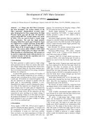
made with <strong>the</strong> LTD-05 switch are shown on Fig. 2 <strong>and</strong><br />
Fig. 3.<br />
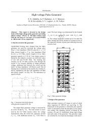
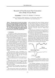
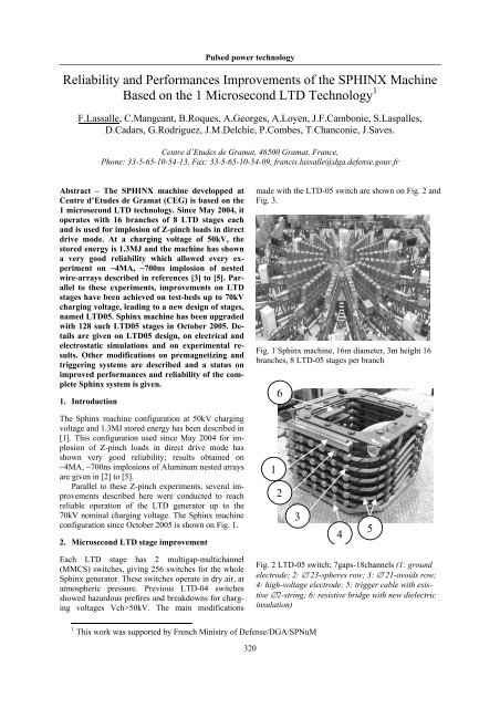
Fig. 1 Sphinx machine, 16m diameter, 3m height 16<br />
branches, 8 LTD-05 stages per branch<br />
6<br />
The Sphinx machine configuration at 50kV charging<br />
voltage <strong>and</strong> 1.3MJ stored energy has been described in<br />
[1]. This configuration used since May 2004 for implosion<br />
<strong>of</strong> Z-pinch loads in direct drive mode has<br />
shown very good reliability; results obtained on<br />
~4MA, ~700ns implosions <strong>of</strong> Aluminum nested arrays<br />
are given in [2] to [5].<br />
Parallel to <strong>the</strong>se Z-pinch experiments, several improvements<br />
described here were conducted to reach<br />
reliable operation <strong>of</strong> <strong>the</strong> LTD generator up to <strong>the</strong><br />
70kV nominal charging voltage. The Sphinx machine<br />
configuration since October 2005 is shown on Fig. 1.<br />
2. Microsecond LTD stage improvement<br />
1<br />
2<br />
3<br />
4<br />
5<br />
Each LTD stage has 2 multigap-multichannel<br />
(MMCS) switches, giving 256 switches for <strong>the</strong> whole<br />
Sphinx generator. These switches operate in dry air, at<br />
atmospheric pressure. Previous LTD-04 switches<br />
showed hazardous prefires <strong>and</strong> breakdowns for charging<br />
voltages Vch>50kV. The main modifications<br />
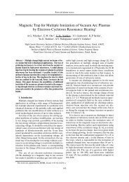
Fig. 2 LTD-05 switch; 7gaps-18channels (1: ground<br />
electrode; 2: ∅ 23-spheres row; 3: ∅ 21-ovoids row;<br />
4: high-voltage electrode; 5: trigger cable with esistive<br />
∅2-string; 6: resistive bridge with new dielectric<br />
insulation)<br />
1 This work was supported by French Ministry <strong>of</strong> Defense/DGA/SPNuM<br />
320
___________________________________________________________________________________________<br />
Poster Session<br />
9 7<br />
8<br />
10<br />
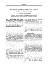
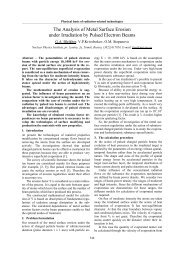
Fig. 3 : LTD-05 switch inside dielectric insulation<br />
(7: new PEHD foils; 8: former PEHD box; 9: new<br />
dielectric insulation <strong>of</strong> <strong>the</strong> trigger-cable connection;<br />
10: capacitor body)<br />
- The high density polyethylene (PEHD) insulation<br />
between <strong>the</strong> spheres electrodes <strong>and</strong> <strong>the</strong> return<br />
current path (switch case at ground) was increased<br />
from 3.5mm to 5.5mm, adding a 2mm<br />
thick PEHD foil (7) on each sides <strong>of</strong> <strong>the</strong> square<br />
switch <strong>and</strong> re-shaping <strong>the</strong> high voltage plate (4).<br />
As shown on Fig. 4 this modification lowers E-<br />
field in <strong>the</strong>se regions thus reducing electrostatic<br />
charges on <strong>the</strong> dielectric surfaces. For example,<br />
from LTD-04 to LTD-05 design maximum E-field<br />
is reduced from 760kV/cm to 370kV/cm in <strong>the</strong><br />
PEHD insulation between <strong>the</strong> 70kV plate (4) <strong>and</strong><br />
<strong>the</strong> ground.<br />
- Each <strong>of</strong> <strong>the</strong> 7 gaps <strong>of</strong> <strong>the</strong> switch was increased<br />
from 5.5mm to 6.5mm by re-machining<br />
half <strong>of</strong> <strong>the</strong> ∅23mm spheres to ∅21mm ovoids (3).<br />
This allows to reduce maximum E-field in gaps;<br />
between <strong>the</strong> 70kV plate (4) <strong>and</strong> <strong>the</strong> first row this<br />
reduction is from 23kV/cm for 5.5mm gap to<br />
18kV/cm for 6.5mm gap.<br />
- The resistive bridge (6) allows an homogeneous<br />
distribution <strong>of</strong> voltage between gaps. The insulation<br />
<strong>of</strong> this bridge was improved adding anticorona<br />
spheres <strong>and</strong> PVC separations between <strong>the</strong><br />
100MΩ resistors. Voltage distribution between<br />
channels was improved by reduction <strong>of</strong> <strong>the</strong> resistance<br />
<strong>of</strong> <strong>the</strong> ∅2mm string (5).<br />
- The insulation <strong>of</strong> <strong>the</strong> trigger cable connection<br />
(9) was modified to avoid surface tramping <strong>and</strong><br />
breakdown between this HV cable <strong>and</strong> <strong>the</strong> LTD<br />
‘convolute’.<br />
These improvement studies were supported by circuit<br />
<strong>and</strong> 2D plus 3D electrostatic simulations, <strong>and</strong> by<br />
tests on two test beds composed <strong>of</strong> 1 <strong>and</strong> 4 LTD<br />
stages.<br />
(a)<br />
(b)<br />
Fig. 4 : Example <strong>of</strong> a 3D-electrostatic simulation (a) :<br />
Efield > 30kV/cm along 1 channel; (b) : Efield topology<br />
on <strong>the</strong> PEHD surface contacting <strong>the</strong> electrodes<br />
The equivalent scheme <strong>of</strong> a single stage is shown<br />
on Fig. 5. Compared to previous LTD-04 design, <strong>the</strong><br />
increased on total inductance is less than 5% <strong>and</strong> is<br />
due to an increase <strong>of</strong> each switch inductance from 6nH<br />
to 9.4nH.<br />
P<br />
CP<br />
LP<br />
20uF 50uH<br />
1 2<br />
IC = 3<br />
Rgage<br />
50 Ohm<br />
0<br />
in1<br />
from previous<br />
LTD stage<br />
in2<br />
Tgage<br />
Z0 = 60 Ohm<br />
Lgage<br />
TD = 55ns<br />
1500nH<br />
2<br />
1<br />
R 2caps 6.5m<br />
L 2caps 5nH<br />
2<br />
C 2caps 7.9uF<br />
U 2switches<br />
1<br />
2<br />
1<br />
core saturation<br />
2<br />
L 2switches 4.7nH<br />
@40kV.us for<br />
Usat_core<br />
2<br />
DB=3.2Tesla<br />
(1core with 17rings)<br />
1<br />
Lsat_core40nH<br />
Lconv_a 4nH<br />
1<br />
Cconv 2<br />
Rcore<br />
1<br />
8.9 Ohm<br />
3.2nF or 19uH<br />
Lconv_b 4nH<br />
2<br />
1Meg<br />
2.5 mOhm<br />
12.7 Ohm1.53ns<br />
R<br />
Tvacuum<br />
1<br />
2<br />
out1<br />
out2<br />
to next<br />
LTD stag<br />
Fig. 5 : Electrical scheme <strong>of</strong> a single LTD-05 stage<br />
The final LTD-05 design showed a good reliability<br />
at <strong>the</strong> nominal 70kV charging voltage: after more than<br />
500 test bed shots <strong>and</strong> without any maintenance, LTD-<br />
05 stages showed no pre-fires <strong>and</strong> no damages.<br />
321
___________________________________________________________________________________________<br />
Pulsed power technology<br />
3. The Sphinx machine with LTD-05 stages<br />
The Sphinx machine has been upgraded with 128 such<br />
LTD05 stages (16 branches <strong>of</strong> 8 stages) <strong>and</strong> shots at<br />
60kV charging voltage on Aluminum Z-pinch loads<br />
began on October 2005.<br />
Pre-magnetizing system<br />
As described in [1], <strong>the</strong> magnetic cores <strong>of</strong> LTD<br />
stages are pre-magnetized during <strong>the</strong> shot sequence. A<br />
60μs rise time pulse is sent through <strong>the</strong> 60Ω cable (see<br />
point P on Fig. 5) around each core <strong>and</strong> <strong>the</strong> main LTD<br />
pulse starts when this pre-magnetization current reach<br />
its maximum ~1.5KA. The polarity <strong>of</strong> <strong>the</strong>se two<br />
pulses is opposite so that <strong>the</strong> Hysteresis swing is<br />
maximum ΔB~3.9Tesla <strong>and</strong> <strong>the</strong> core, which cross<br />
section is 7.4.10 -4 m 2 , can withst<strong>and</strong> a Volt.Second<br />
integral <strong>of</strong> 49kV.μs before saturation. To insulate <strong>the</strong><br />
core circuit <strong>and</strong> <strong>the</strong> load circuit during <strong>the</strong> premagnetization,<br />
a self-closing vacuum surface switch<br />
named ‘P-switch’ is installed on <strong>the</strong> ground side (opposite<br />
to <strong>the</strong> load) <strong>of</strong> each coaxial LTD branch.<br />
Several problems appeared during first shots on<br />
<strong>the</strong> LTD-05 upgraded Sphinx. Some <strong>of</strong> <strong>the</strong>m were due<br />
to minor defaults on LTD switches assemblies; <strong>the</strong>y<br />
affected only few stages <strong>and</strong> were easily solved. More<br />
awkward were breakdowns occurring mainly on <strong>the</strong><br />
LTD stages located on ground side. The analysis<br />
showed that <strong>the</strong>se breakdowns were due to overvoltages<br />
created during closing <strong>of</strong> <strong>the</strong> P-switches. A<br />
redesign allowed to reduce <strong>the</strong> jitter <strong>and</strong> <strong>the</strong> closing<br />
delay <strong>of</strong> <strong>the</strong> 16 P-switches, so reducing <strong>the</strong> overvoltages<br />
<strong>and</strong> breakdown risks. This modification improved<br />
a lot <strong>the</strong> reliability <strong>of</strong> <strong>the</strong> machine for fur<strong>the</strong>r<br />
shots.<br />
New pre-magnetizing generator<br />
Despite this good result, it was decided to develop<br />
a new pre-magnetization system which will be on line<br />
from June 2006. A new compact generator has been<br />
built to generate a (1.5KA, 18μs rise time, single polarity)<br />
pulse on each core. This generator is based on 2<br />
parallel LTD stages modified with single gap, single<br />
channel switches <strong>and</strong> liquid resistors.The premagnetizing<br />
pulse is applied several hours before <strong>the</strong><br />
shot, before connection <strong>of</strong> <strong>the</strong> load, on <strong>the</strong> ground side<br />
<strong>of</strong> <strong>the</strong> inductive support (see Fig. 1 & point P on Fig.<br />
6) <strong>and</strong> distributes throught <strong>the</strong> convolute to <strong>the</strong> cores.<br />
To close <strong>the</strong> pre-magnetizing circuit, <strong>the</strong> 16 P-<br />
switches are replaced by fixed short-circuits, giving<br />
<strong>the</strong> benefit during <strong>the</strong> shot to suppress <strong>the</strong> overvoltage<br />
risks described previously. With this system,<br />
<strong>the</strong> cores pre-magnetized at –Br have a ΔB~3.2Tesla<br />
Hysteresis swing <strong>and</strong> can withst<strong>and</strong> a Volt.Second<br />
integral <strong>of</strong> 40kV.μs before saturation.<br />
Prepulse generator for wire-arrays pre-heating<br />
Thanks to <strong>the</strong> new pre-magnetizing generator, <strong>the</strong><br />
former system can be removed or used for o<strong>the</strong>r application.<br />
This system is composed <strong>of</strong> 8 generators, each<br />
<strong>of</strong> <strong>the</strong>m associated to 2 LTD branches, <strong>and</strong> can be<br />
triggered independantly. Each generator gets itself<br />
several outputs which are connected to <strong>the</strong> point P <strong>of</strong><br />
LTD stages (see Fig. 5). As all P-switches are now<br />
short-circuited, main part <strong>of</strong> <strong>the</strong> discharge current goes<br />
to <strong>the</strong> low impedance circuit <strong>of</strong> <strong>the</strong> Z-pinch load.<br />
Measurements, also fitted by circuit simulations, show<br />
that <strong>the</strong>se generators can deliver, for each <strong>of</strong> <strong>the</strong> 16<br />
lines, a prepulse up to 1.3kA with a 50μs rise time in<br />
<strong>the</strong> load. Choosing <strong>the</strong> number <strong>of</strong> generators, <strong>the</strong><br />
number <strong>of</strong> outputs, <strong>the</strong> charging voltage <strong>and</strong> <strong>the</strong> triggering<br />
time, this allows a large range <strong>of</strong> possible prepulses,<br />
going from few 100A to 20 KA, with rise<br />
times from few μs to 60 μs before <strong>the</strong> main LTD<br />
pulse.<br />
First results <strong>of</strong> Aluminum nested wire-arrays using<br />
this prepulse for wires pre-heating are given in [4] <strong>and</strong><br />
[5].<br />
Triggering system<br />
The trigger system fires each <strong>of</strong> <strong>the</strong> 256 LTD<br />
switches. Triggering operation <strong>of</strong> <strong>the</strong> LTD switch is<br />
based on a pulsed distortion <strong>of</strong> <strong>the</strong> electrical field<br />
between gaps, created by a controlled discharge <strong>of</strong> <strong>the</strong><br />
HV trigger cable (5) going through <strong>the</strong> spheres electrodes<br />
(see Fig. 2). As <strong>the</strong> only trigger energy is <strong>the</strong><br />
energy stored in <strong>the</strong> HV cables, this system is compact,<br />
simple <strong>and</strong> reliable. The complete system is<br />
based on a 2 steps switches cascade described in [1].<br />
The "trig-trig" switch <strong>and</strong> <strong>the</strong> 16 "trigger" ones are<br />
identical <strong>and</strong> are based on <strong>the</strong> same technology as<br />
LTD switches. Trigger cables are charged at 55kV in<br />
about 30s with an independent high voltage power<br />
supply. The “trig-trig” <strong>and</strong> “trigger” switches are been<br />
improved: reduction <strong>of</strong> gaps from 9 to 7, better repartition<br />
<strong>of</strong> impedance between <strong>the</strong> channels. First improvements<br />
made on <strong>the</strong> 16 trigger switches has<br />
shown, within each branch a reduction <strong>of</strong> <strong>the</strong> spread<br />
from 20ns to 10ns between closing time <strong>of</strong> <strong>the</strong> 8 LTD<br />
stages. These modifications, when completed on June<br />
2006, should allow to improve significantly <strong>the</strong> global<br />
jitter <strong>of</strong> all LTD switches, with a spread between <strong>the</strong><br />
16 lines reduced from 50 ns to less than 30 ns.<br />
4. Status on Sphinx performances<br />
A simplified electrical scheme <strong>of</strong> <strong>the</strong> Sphinx generator<br />
is given in Fig. 6. The values with LTD labels are <strong>the</strong><br />
equivalent capacitance, inductance <strong>and</strong> resistance <strong>of</strong><br />
<strong>the</strong> 256 LTD-05 stages distributed in 16 parallel<br />
branches <strong>of</strong> 8 stages.<br />
322
___________________________________________________________________________________________<br />
Poster Session<br />
CLTD ULTD LLTD RLTD Lline200 Lline70<br />
1 21 2 1 2<br />
1 2<br />
15.8u<br />
18.5nH 5m 2.84nH 2.52nH<br />
TCLOSE = 0n<br />
IC = {VCH}<br />
0<br />
ROPEN = 1Meg<br />
TTRAN = 10n<br />
RCLOSED = 1.25m<br />
VCH = 8 * 0.95 * Vch<br />
Vch = 50 kV to 70 kV<br />
Lconv1<br />
1 2<br />
4.2nH<br />
Lsupport<br />
520nH<br />
P<br />
2<br />
1<br />
0<br />
1<br />
2<br />
Lconv2<br />
4.6nH<br />
1<br />
out in<br />
0<br />
R<br />
2m<br />
2<br />
Lconnexion<br />
8.5nH<br />
1<br />
Zpinch load<br />
Fig. 6 :Simplified electrical scheme <strong>of</strong> <strong>the</strong> complete<br />
Sphinx generator with 16 branches <strong>and</strong> 8 LTD-05<br />
stages per branch.<br />
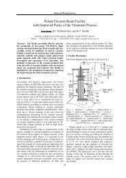
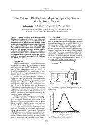
The Fig. 7 compares experimental data on nested<br />
aluminum wire-arrays loads with a 700ns implosion<br />
time. The new LTD-05 stages allow an increasing <strong>of</strong><br />
charging voltage from 50kV to 60kV which gives for<br />
<strong>the</strong>se 2 shots a maximum current going from 4MA to<br />
4.6MA <strong>and</strong> a radiated energy E>1kev from 17kJ to<br />
27kJ with a FWHM around 50 ns. More details on Z-<br />
pinch loads, with results on radial <strong>and</strong> axial radiated<br />
powers <strong>and</strong> analysis <strong>of</strong> <strong>the</strong> influence <strong>of</strong> a prepulse for<br />
preheating wires are presented in [4] <strong>and</strong> [5].<br />
Up to now, around 10 successive shots at 60kV<br />
charging voltage have been done without maintenance<br />
<strong>of</strong> <strong>the</strong> new LTD-05 stages <strong>and</strong> showed no defaults.<br />
This analysis <strong>of</strong> Sphinx generator reliability at<br />
Vch=60kV will continue while improving <strong>the</strong> wirearrays<br />
loads <strong>and</strong> testing a new 200mm triple gas-puff<br />
load. If reliability is confirmed on <strong>the</strong> whole generator<br />
as it was on test-beds, first shots at Vch=70kV will be<br />
starting to improve <strong>the</strong> Sphinx performances.<br />
current (A)<br />
7M<br />
6M<br />
5M<br />
4M<br />
3M<br />
2M<br />
1M<br />
0<br />
SPHINX : #540 @ 50kV &<br />
Iload561_data<br />
Iload540_data<br />
Istatic.load_sim.60kV<br />
Istatic.load_sim.70kV<br />
0 500n 1µ<br />
time (s)<br />
#561 @ 60kV<br />
X561<br />
X540<br />
500G<br />
Fig. 7 : Sphinx current <strong>and</strong> Xray>1keV radiated<br />
power for an Aluminum nested wire arrays load.<br />
(solid lines : shot at Vch=60kV; dot lines : shot at<br />
Vch=50kV; grey lines : simulation at Vch=60kV <strong>and</strong><br />
Vch=70kV for a static 1.3nH, 15mΩ load )<br />
0<br />
power Xray >1keV (W)<br />
At 60kV charging voltage, <strong>the</strong> Sphinx generator<br />
stores 1.8MJ <strong>and</strong> reach 4.6MA on a 700ns wire-array<br />
load, which would correspond to a 6.2MA, 1.1μs<br />
discharge on a static load ( see <strong>the</strong> grey line simulation<br />
on Fig. 7 for a 1.3nH,15mΩ load). At Vch=70kV, <strong>the</strong><br />
stored energy will be 2.5MJ, reaching 5.4MA on a<br />
700ns load <strong>and</strong> 7.3 MA on a same static load.<br />
An o<strong>the</strong>r short term way to improve performances<br />
is to add LTD stages. The architecture <strong>of</strong> <strong>the</strong> machine<br />
is designed to accept up to 10 stages per branch <strong>and</strong><br />
LTD values on <strong>the</strong> equivalent scheme <strong>of</strong> Fig. 6 can be<br />
easily modified to analyze <strong>the</strong> new coupling with a z-<br />
pinch load. The configuration with 9 LTD-05 stages<br />
per branch will be on line on June 2006 <strong>and</strong> should be<br />
increased to 10 stages on 2007 depending on funding.<br />
5. Conclusion<br />
<strong>Improvements</strong> made on microsecond LTD stages now<br />
allows to fire routinely <strong>the</strong> Sphinx machine at 60kV<br />
charging voltage, giving 1.8MJ stored energy <strong>and</strong><br />
4.6MA on a 700ns implosion time load. These new<br />
LTD-05 stages will allow during next months to continue<br />
<strong>the</strong> increase <strong>of</strong> performances by going to 70kV<br />
charging voltage <strong>and</strong> 9 stages per branch. The objective<br />
is to validate <strong>the</strong> reliability <strong>of</strong> Sphinx machine in<br />
this new configuration by <strong>the</strong> end <strong>of</strong> 2006.<br />
For <strong>the</strong> longer term, several independent or combined<br />
options are under study for fur<strong>the</strong>r increase <strong>of</strong><br />
Sphinx performances : current multiplier, 500ns rise<br />
time LTD stages with new capacitors, 1μs to few<br />
100ns power amplifier <strong>and</strong> LTD stages working at<br />
Vch=90kV.<br />
References<br />
[1] Ch.Mangeant et al., in Proc. 13th Symposium on<br />
High Current Electronics, Tomsk, July 2004,<br />
pp.111-114<br />
[2] F.Lassalle et al., in Proc. 13th Symposium on High<br />
Current Electronics, 2004, pp.323-326<br />
[3] H.Calamy et al., in AIP Conf. Proc., vol. 808,<br />
2006, pp. 15-20.<br />
[4] H.Calamy et al., “Characterization <strong>and</strong> Improvement<br />
<strong>of</strong> 800ns Implosion Time Aluminum Nested<br />
Arrays on Sphinx Machine” presented at 14th<br />
Symp. on High Current Electronics,Tomsk,<br />
Sept.2006.<br />
[5] F.Hamann et al., «First hohlraum experiments<br />
using axial flux on <strong>the</strong> Sphinx machine», in 33rd<br />
IEEE ICOPS, June 2006.<br />
323