this pdf excerpt
this pdf excerpt
this pdf excerpt

You also want an ePaper? Increase the reach of your titles
YUMPU automatically turns print PDFs into web optimized ePapers that Google loves.
.-"<br />
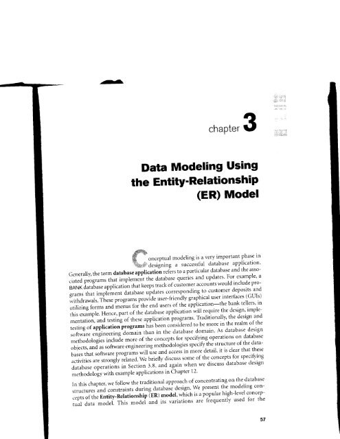
clrapter 3<br />
Data Modeling Using<br />
the EntitY'RelationshiP<br />
(ER) Model<br />
#%-<br />
fi i<br />
rrl;:,",.i;,;<br />
ffi onceptual modeling is a very important phase in<br />
E,;,, n a.rigning a successtul database application'<br />
Generally, the term database applicatio-n ,efirs to a particular database and the associated<br />
programs that t-pr.-Jtitthe database<br />
example' a<br />
oY"it:<br />
T1i*lll,,f"t<br />
BANKdatabaseapplicationthatkeepstrackofcustomeraccountswouldincludeprogranrsthatimplemerrtdatabaseupdut",correspondinqlo:ustoTerdepositsand<br />
rvithdrawals. These progil;t;;";id" user-fiienily graphical user'intertaces (GUIs)<br />
utilizing forms and foithe end users of the a'ppiication-the bank tellers' in<br />
<strong>this</strong> example. Hence, -"rlu, p".i in. database application will require the design, irnple-<br />
"i<br />
mentation, and testing of these application programs' Traditionally, the design and<br />
testing of application programs has been consiiere
7-<br />
58 Chapter 3 Data Modeling Using the Entity-Relationship (ER) Model<br />
conceptual design of database applications, and many database design tools emplor'<br />
its concepts. We describe the basic data-structuring concepts and constraints of tht<br />
ER rnodel and discuss their use in tl-re design of cor.rceptual schemas for database<br />
applictrtions. We also present the diagrammatic notation associated with the ER<br />
model, known as ER diagrams.<br />
Object modeling methodologies such as the Universal Modeling Language (UMLr<br />
are becoming increasingly popular in software design and engineering. These<br />
methodologies go beyond database design to speci$, detailed design of software<br />
modules and their interactions using various types of diagrams. An irnportant part<br />
of these methodologies-namely, class diagran 15)-i11g similar in many rvays to the<br />
ER diagrams. In class cliagrams, opcratiotts on objects are specified, in addition to<br />
specilying the database schema structure. Operations can be used to specify the<br />
functional recluiretttents during database design, as discussed in Section 3.1. We presellt<br />
some of the UML notation and concepts for class diagrams that are particularh'<br />
relevant to database design in Section 3.8, and briefly compare these to ER notation<br />
and concepts. Additional UML notation and concepts are presented in Section 4.6<br />
and itr Chapter 12.<br />
This chaprter is organized as follorvs: Section 3.1 discusses the role of high-level conceptual<br />
data models in database design. We introduce the requirements fbr an<br />
example database application in Section 3.2 to illustrate the use of concepts fionr<br />
the ER model. This example databirse is also used in subsequent chapters. In Section<br />
3.3 we present the concepts of entities and attributes, and we gradually introduce<br />
the diagrammatic technique tbr displaying an ER scherna. In Section 3.4 we introduce<br />
the concepts ofbinary relationships and their roles and structural constraints.<br />
Section 3.5 introduces weak entity types. Section 3.6 shows how a schema design is<br />
refined to include relationships. Section 3.7 reviews the notation for ER diagrams,<br />
summarizes the issues that arise in schema design, and discusses how to choose the<br />
names for database schemtr constructs. Section 3.8 introduces some UML class diagram<br />
concepts, compirres thenr to ER model concepts, and applies them to the sarne<br />
database exarmple. Section 3.9 discusses more complgx types of reiationships.<br />
Section 3.10 summarizes the chapter.<br />
The material in Sections 3.8 and 3.9 may be excluded from an introductory course;<br />
if a more thorough coverage of data modeling concepts and conceptual database<br />
design is desired, the reac-ler should continue from Section 3.7 to Chapter 4, where<br />
we describe extensions to the ER nrodel that lead to the Enhanced-ER (EER) model,<br />
which inclucies concepts such as specialization, generalization, inheritance, and<br />
union types (categories). We also introduce some adclitional Ulv{L concepts and<br />
notation in Chapter 4.<br />
1, A class is similar Io an entity type in many ways.
luy<br />
the<br />
'ilSe<br />
ER<br />
'{L)<br />
r-Se<br />
'il re<br />
)ilrt<br />
the<br />
lto<br />
the<br />
)re-<br />
:rly<br />
lon<br />
-1.6<br />
on-<br />
'an<br />
'om<br />
.lon<br />
uce<br />
tronts.<br />
.n is<br />
lTls,<br />
the<br />
dia-<br />
Itne<br />
ipr s.<br />
lrse;<br />
lase<br />
:)ere<br />
,iel,<br />
and<br />
and<br />
.fl<br />
3.1 Using High-Level Conceptual Data Models for Database Design 59<br />
3.1 Using High-Level Conceptual<br />
Data Models for Database Design<br />
Figure 3.1 shows a simplified description of the database design process. The first<br />
step shown is requirements collection and analysis. During <strong>this</strong> step, the database<br />
designers interview prospective database users to understand and document their<br />
data requirements. The result of <strong>this</strong> step is a concisely written set of users' requirements.<br />
These requirements should be specified in as detailed and complete a form<br />
as possible. In parallel with specifring the data requirements, it is useful to specify<br />
the known functional requirements of the application. These consist of the userdefined<br />
operations (or transactions) that will be applied to the database, including<br />
Functional Requirements<br />
+<br />
@ +<br />
DBMS-independent<br />
I DBMS-specific<br />
I<br />
High-Level Transaction<br />
Specification<br />
Application Programs<br />
@<br />
@<br />
REOUIREMENTS<br />
COLLECTION AND<br />
ANALYSIS<br />
Data Requirements<br />
t<br />
V<br />
Conceptual Schema<br />
(ln a high-level data model)<br />
+<br />
| (DATA MODEL MAPPTNG) |<br />
V<br />
Logical (Conceptual) Schema<br />
-<br />
(ln the data model of a specific DBMS)<br />
ernal Schema<br />
Figure 3.1<br />
A simplified diagram<br />
to illustrate the<br />
main phases of<br />
t^+^f,^^^ t^^i^^<br />
udr4uass uE>19il.
Chapter 3 Data Modeling Using the Entity-Relationship (ER) Model<br />
both retrievals and updates. In soflware design, it is common Io use dsta Jlow diagronts,<br />
sequence diagrttms, scartorios, and other techniques to specify functional<br />
requirements. We lvill not discuss any of these techniques here; they are usr.rallr<br />
described in detail in software engineering texts. We give an overview of some ot<br />
these techniques in Chapter 12.<br />
Once all the requirements have beer-r collected and analyzed, the next step is to crt'atr'<br />
a conceptual scherna for the database, using a high-level conceptual data rnodel.<br />
This step is called conceptual design. The conceptual schema is a concise description<br />
of the data requirements of the users irnd includes detailed descriptions of the entitr<br />
types, relationships, and constraints; these are expressed using the concepts provided<br />
by the high-level data model. Because these concepts do not include implementation<br />
details, they are usr.rally easier to understand and can be used to communicate rvith<br />
nontechnical users. The high-level cor-rceptual schema can also be used as a referencc<br />
to ensure that all users'data requirements are met and that the requirements do nor<br />
conflict. This approach enabies database designers to concentrate on specifing thc<br />
properties of the data, without being concerned rvith storage details. Consequently, it<br />
is easier fbr them to create a good conceptual database design.<br />
During or after the conceptuirl schema design, the basic data model operations can<br />
be used to specily the high-level user operations identified during tirnctional analr -<br />
sis. This also serves to confirm that the conceptual schema meets all the identifiec<br />
functional requirements. Modifications to the conceptual schema can be introduced<br />
if some functional requirements cannot be specified using the initiai schenra<br />
The next step in database design is the actual implementation of the database, usins<br />
a commercial DBNrlS. Most current commercial DBMSs use an implementatior:<br />
data model-such as the relational or the object-relational database rnodel-so th.<br />
conceptual schema is transformed from the high-level data model into the implementation<br />
data model. This step is called logical design or data model mapping; it.<br />
result is ar database schema in the implementation clata model of the DBMS.<br />
The last step is the physical design phase, during which the internal storage strLrctures,<br />
indexes, access paths, ar-rd file organizations for the database files are specified.<br />
In parallel with tl-rese activities, application programs are designed and implcmented<br />
as databirse transactions corresponding to the high-level transaction speci<br />
fications. We discuss the database design process in more detail in Chapter 12.<br />
We present only the basic ER n-rodel concepts for conceptutrl schema clesign in thi.<br />
chapter. Additional modeling concepts are discussed in Chapter 4, when we intro'<br />
duce the EER model.<br />
3.2 An Example Database Application<br />
In <strong>this</strong> section we describe an example database application, called COMPANY<br />
which serves to illustrate the basic ER model concepts and their use iu schenr.<br />
design. We list the data requirements for the database here, and then create its conceptual<br />
schema step-by-step as we ir-rtroduce the modeling concepts of the EIi
t diaiional<br />
sually<br />
nrc of<br />
create<br />
roclel.<br />
iption<br />
cntity<br />
'r'ided<br />
t.ltior-l<br />
,'n'ith<br />
-'rcllce<br />
kr not<br />
rtr the<br />
,t..'.<br />
ntlr', it<br />
Llslng<br />
t.rtion<br />
:o the<br />
,r. t.! e -<br />
ng; its<br />
st ruccitred.<br />
,r. t-l c-<br />
speci-<br />
in <strong>this</strong><br />
lnlro-<br />
PANY,<br />
:hema<br />
s collhe<br />
ER<br />
.^3.<br />
3.3 Entity Types, Entity Sets, Attributes, and Keys<br />
model. The COMPANY database keeps track of a company's employees, departments,<br />
and projects. Suppose that after the requirements collection and analysis<br />
phase, the database designers provide the following description of the miniworldthe<br />
part of the company to be represented in the database.<br />
,;: The company is organized into departments. Each department has a unique<br />
name, a unique number, and a particular employee who manages the<br />
department. We keep track of the start date when that employee began managing<br />
the department. A department may have several locations.<br />
,p A department controls a number of projects, each of which has a unique<br />
name, a unique number, and a single location.<br />
# We store each employee's name, social security number,2 address, salary, sex,<br />
and birth date. An employee is assigned to one department, but may work on<br />
several projects, which are not necessarily controlled by the same department.<br />
We keep track of the number of hours per week that an employee<br />
works on each project. We also keep track of the direct supervisor of each<br />
employee.<br />
s We want to keep track of the dependents of each employee for insurance<br />
purposes. We keep each dependent's first name, sex, birth date, and relationship<br />
to the employee.<br />
Figure 3.2 shows how the schema for <strong>this</strong> database application can be displayed by<br />
means of the graphical notation known as ER diagrams. This figure will be<br />
explained gradually as the ER model concepts are presented. we describe the stepb)'-step<br />
process of deriving <strong>this</strong> schema from the stated requirements-and explain<br />
the ER diagrammatic notation-as we introduce the ER model concepts.<br />
3.3 Entity Types, Entity Sets,<br />
Attributes, and Keys<br />
The ER model describes data as entities, relationships, and attribute.s. In Section 3.3.I<br />
\ve introduce the concepts of entities and their attributes. we discuss entity types<br />
and key attributes in Section 3.3.2. Then, in Section 3.3.3, we specifo the initial conceptual<br />
design of the entitv types for the coMPANY database. Relationships are<br />
described in Section 3.4.<br />
3.3.1 Entities and Attributes<br />
Entities and Their Attributes. The basic object that the ER model represents is an<br />
entity, which is a thing in the real world with an independent existence. An entity<br />
2. The social security number, or SSN, is a unique nine-digit identifier assigned to each rndividual in the<br />
United States to keep track of his or her employment, benefts, and taxes. Other countries may have simar<br />
identif catron schemes, such as persona dentification card numbers,<br />
61
Chapter 3 Data Modeling Using the Entity-Relationship (ER) Model<br />
Supervisor<br />
Supervisee<br />
DEPENDENTS_OF<br />
DEPENDENT<br />
Figure 3.2<br />
An ER schema diagram for the coMPANY database. The diagrammatic notation<br />
is introduced gradually throughout <strong>this</strong> chapter.<br />
may be an object with a physical existence (for example, a particular person, car,<br />
house, or ernployee) or it rlay be an object with a conceptual existence (for example,<br />
a company, a job, or a university course). Each entity has attributes-the pariicular<br />
properties that describe it. For example, an EMPLOYEE entity may be<br />
described by the employee's name, age, address, salary, and job. A particular entitl'<br />
wili have a value for each of its attributes. The attribute values that describe each<br />
entity become a major part of the data stored in the database.<br />
:=ili€
't<br />
---,--:-.:<br />
JmoeI<br />
-_==-?'<br />
T<br />
:5o11, car,<br />
or exam-<br />
-tlrc rrrr-<br />
nray be<br />
l.rr entity<br />
ribc each<br />
"d.<br />
3.3 Entity Types, Entity Sets, Attributes, and Keys<br />
Figure 3.3 shows two entities and the values of their attributes. The EMPLOYEE<br />
r'ntity el has four attributes: Name, Address, Age, and Home_phone; their values are<br />
'lohn<br />
Smith,''231I Kirby,''Houston, Texas 77001,''55,' and '713-749-2630,' respectively.<br />
The COMPANY entity c, has three attributes: Name, Headquarters, and<br />
Dresident; their values are'Sunco Oil,"Houston,'and'John Smith,'respectively.<br />
Several types of attributes occur in the ER model: simple versus composite, single-<br />
',dued versus multivalued, and stored versus derived. First we define these attribute<br />
tvpes and illustrate their use via examples. Then we introduce the concept of a N U LL<br />
', alue for an attribute.<br />
Composite versus Simple (Atomic) Attributes. Composite attributes can be<br />
Jivided into smaller subparts, which represent more basic attributes with independent<br />
meanings. For example, the Address attribute of the EMPLOYEE entity shown<br />
in Figure 3.3 can be subdivided into Street_address, City, State, and Zip,3 with the values<br />
'2311 Kirbyl 'Houston', 'Texas', and'77001.'Attributes that are not divisible are<br />
called simple or atomic attributes. Composite attributes can form a hierarchy; for<br />
crample, Street_address can be subdivided into three simple attributes: Number,<br />
Street, and Apartment_number, as shown in Figure 3.4. The value of a composite<br />
.rttribute is the concatenation of the values of its constituent simple attributes.<br />
Composite attributes are useful to model situations in which a user sometimes<br />
refers to the composite attribute as a unit but at other times refers specifically to its<br />
components. If the composite attribute is referenced only as a whole, there is no<br />
need to subdivide it into component attributes. For example, if there is no need to<br />
refer to the individual components of an address (ZIP Code, street, and so on), then<br />
the whole address can be designated as a simple attribute.<br />
Single-Valued versus Multivalued Attributes. Most attributes have a single<br />
r-alue for a particular entity; such attributes are called single-valued. For example,<br />
Age is a single-valued attribute of a person. In some cases an attribute can have a set<br />
Name: John Smith<br />
Address: 231 1 Kirby<br />
Houston, Texas 77001<br />
Age:55<br />
Home_phone : 7 1 3-749-2630<br />
3. ZIP Code is the name used in the Un ted States for a f ve-dioit oostal code<br />
Name: Sunco Oil<br />
Headquarters : Houston<br />
President: John Smith<br />
trn,4Dt .\vtrtr<br />
63<br />
Figure 3.3<br />
Two entities,<br />
^ ^^;<br />
Llvll LV I LL Cl I al lU<br />
COMPANY c,, and<br />
their attributes,
Chapter 3 Data Modeling Using the Entity-Relationship (ER) Model<br />
Figure 3.4<br />
A hierarchy of<br />
composite attributes.<br />
Address<br />
Street_address City State<br />
,,"1\ ,/l\<br />
./l\<br />
/\<br />
Number Street Apartment_number<br />
of values for the same entity-for example, a Colors attribute for a car, or .i<br />
College-degrees attribute fbr a person. Cars with one color have a single valr,rc.<br />
whereas two-tone cars have two color values. Similarly, one person may not have .r<br />
college degree, another person may have one, altd a third person rray have two or<br />
more degrees; therefore, different persons can have different ruunbers of values fctr<br />
the College_degrees attribute. Such attributes are called multivalued. A rnultivalued<br />
attribute may have lower and upper bounds to constrain the number of value:<br />
allowed for each individual entity. For example, the Colors attribute of a car may havc<br />
between one and three values, if we assume that a car can have three colors at most.<br />
Stored versus Derived Attributes. In some cases, two (or more) attribute values<br />
are related-fbr example, the Age and Birth-date attributes of a person. For a<br />
particular person entity, the value of Age can be determined from the current<br />
(today's) date and the value of that person's Birth-date. The Age attribute is hencc<br />
called a derived attribute and is said to be derivable from the Birth-date attribute.<br />
which is cailed a stored attribute. Some attribute values can be derived fronr<br />
related entities; for example, an attribute Number-of-employees of a DEPARTMENT<br />
entity can be derived by counting the number of employees related to (workins<br />
for) that department.<br />
NULL Values. In some cases, a particular entity may not have an applicable value<br />
for an attribute. For example, the Apartment-number attribute of an address applies<br />
only to addresses that are in apartment buildings and not to other types of residences,<br />
such as single-family homes. Similariy, a College-degrees attribute applies<br />
only to persons with college degrees. For such situations, a special value called N U LL<br />
is created. An address of a single-family home would have NULL for its<br />
Apartment-number attribute, and a person with no college degree would have NULL<br />
for College-degrees. NULL can also be used if we do not know the value of an attribute<br />
for a particuiar entity-for example, if we do not know the home phone number<br />
of 'John Smith'in Figure 3.3. The meaning of the former type of NULL is not<br />
applicable, whereas the meaning of the latter is unknown.The unknowfi category ot<br />
can be further classified into two cases. The first case arises rvhen it is known that
aJr. or a<br />
.lc vi.rlue,<br />
()l hal\re a<br />
. d t\\'o or<br />
,i/rrc-s for<br />
;itir alued<br />
.'l-r'alues<br />
:n.n have<br />
.it ntost.<br />
5utc valr)n.<br />
For a<br />
-'current<br />
' i: hence<br />
.rr t ribute,<br />
, cd iror-n<br />
\RTMENT<br />
rr orking<br />
rl.lc value<br />
.. .rpplies<br />
'r oi resitc<br />
.rpplies<br />
Ilcd NULL<br />
L firr its<br />
.trc'NULL<br />
.rn iittrib-<br />
)llL'llLllTl-<br />
JLL rs lrot<br />
rtcgorY of<br />
l()\\'ll that<br />
,3,<br />
3.3 Entity Types, Entity Sets, Attributes, and Keys<br />
the attribute value exists but is missing-for example, if the Height attribute of a person<br />
is listed as N U LL. The second case arises when it is not known whether the attribute<br />
value exists-for example, if the Home-phone attribute of a person is NULL.<br />
Complex Attributes. Notice that composite and multivalued attributes can be<br />
nested arbitrarily. We can represent arbitrary nesting by grouping components of a<br />
cttmposite attribute between parentheses 0 and separating the components with<br />
commas, and by displaying multivalued attributes between braces {}. Such attributes<br />
are called complex attributes. For example, if a person can have more than one<br />
residence and each residence can have a single address and multiple phones, an<br />
rttribute Address_phone for a person can be specified as shown in Figure 3.5.4 Both<br />
Phone and Address are themselves composite attributes.<br />
3.3.2 Entity Types, Entity Sets, Keys, and Value Sets<br />
Entity Types and Entity Sets. A database usually contains groups of entities that<br />
.rre similar. For example, a company employing hundreds of employees may want to<br />
similar information concerning each of the employees. These employee enti-<br />
'tore<br />
ties share the same attributes, but each entity has tIs own value(s) for each attribute.<br />
..\rr entitytype defines a collection (or sef) of entities that have the same attributes.<br />
Each entity type in the database is described by its name and attributes. Figure 3.6<br />
:hows two entity types: EMPLOYEE and COMPANY, and a list of attributes for each.<br />
\ t-ew individual entities of each type are also illustrated, along with the values of<br />
their attributes. The collection of all entities of a particular entity type in the datab.ise<br />
at any point in time is called an entity set; the entity set is usually referred to<br />
using the same name as the entity type. For example, EMPLOYEE refers to both a<br />
rvpe of entity as well as the current set of all employee entities in the database.<br />
.\n entity type is represented in ER diagramss (see Figure 3.2) as a rectangular box<br />
cnclosing the entity type name. Attribute names are enclosed in ovals and are<br />
.itttrched to their entity type by straight lines. Composite attributes are attached to<br />
their component attributes by straight lines. Multivalued attributes are displayed in<br />
.louble ovals. Figure 3.7(a) shows a CAR entity type in <strong>this</strong> notation.<br />
iAddress_phone( {Phone(Area_code,Phone_numbed},Address(Street_address<br />
(Number,Street,Apartment_number),City,State,Zip) ))<br />
tror those familiar with XML, we should note that complex attributes are sim lar to complex elements ln<br />
\1 L (see Chapter 27),<br />
We use a notation for ER diagrams that rs close to the original proposed notation (Chen 1976), Many<br />
.er notatrons are in use; we illustrate some of them later n th s chapter when we present UML class<br />
agrams and in Appendix A.<br />
65<br />
Figure 3.5<br />
A complex attribute:<br />
Arldrocc nhnna
T-<br />
Chapter 3 Data Modeling Using the Entity-Relationship (ER) Model<br />
Figure 3.6<br />
Two entity types, EMPLOYEE<br />
and COMPANY, and some<br />
member entities of each.<br />
Entity Type Name: EMPLOYEE<br />
Entity Set:<br />
(Extension)<br />
Name, Age, Salary<br />
COMPANY<br />
Name, Headquarters, President<br />
c1 o<br />
(Sunco Oil, Houston, John Smith)<br />
C2o<br />
(Fast Computer, Dallas, Bob King)<br />
Arr entity type describes the schema or intension for a set of entities tirat share thc<br />
same structure. The collection of entities of a particular entity type is grouped into<br />
an entity set, which is also called the extension of the entity t)'pe.<br />
Key Attributes of an Entity Type. An important constrainr on rhe entities of an<br />
entity type is the key or uniqueness constraint on attributes. An entity type usuallr<br />
hars an attribute whose values are distinct for each individual entity in the entity set.<br />
Such an attribute is calied a key attribute, and its values can be useci to identifr<br />
each entity uniquely. For exarnple, the Name attribute is a key of the coMpANy<br />
entity type in Figure 3.6 because no two companies are allowed to have the same<br />
name. For the PERSoN entity type, a typical key attribute is ssn (Social Securitr<br />
Number). Sornetirnes several attributes together form a key, meaning that the corrrbination<br />
of the attribute values must be distinct for each entity. If a set of attributes<br />
possesses <strong>this</strong> propertv, the proper way to represent <strong>this</strong> in the ER model that wr'<br />
describe here is to define a contposite attribute and designate it as a key attribute oi<br />
the entity type. Notice that such a composite key rnust be ntirtintal; that is, all component<br />
attributes must be included in the composite attribute to have the uniqueness<br />
property. Superfluous attributes must not be included in a key. In ER<br />
diagrammatic r.rotatior-r, each key attribute has its name underlined inside the oval.<br />
as illustrated in Figure 3.7(a).<br />
Specifying thirt an attribr.rte is a key of an entitv type means that the preceding<br />
uniqueness property rnust hold for every cntitl,5gs of the entitv type. Hence, it is.r<br />
constrair-rt that prohibits any two entities from having the same value for the ker<br />
attribute at the same time. It is not the property of a particular extensiorr; rather, ir<br />
is a constraint on a// e-rtensiotls of the entitv type. This key constraint (and other<br />
constraints we di-scr.rss later) is derived from the constraints of the miniworld that<br />
the database re[)resen ts.
.rre the<br />
,.d into<br />
sofan<br />
.rsually<br />
itv set.<br />
I'ntifr<br />
/PANY<br />
:'SilITl€<br />
-lrlrrL/<br />
a c0n1ributes<br />
hat lve<br />
)ute of<br />
Icomrllque-<br />
In ER<br />
Lc oval,<br />
,'.'dir-rg<br />
.itisa<br />
he key<br />
ther, it<br />
I other<br />
ld that<br />
.3"<br />
3.3 Entity Types, Entity Sets, Attributes, and Keys<br />
Some entity types have more than one key attribute. For example, each of the<br />
Vehicle_id and Registration attributes of the entity type CAR (Figure 3.7) is a key in its<br />
orvn right. The Registration attribute is an example of a composite key formed from<br />
trvo simple component attributes, State and Number, neither of which is a key on its<br />
orvn. An entity type may also have no key,in which case it is called a weak entity type<br />
see Section 3.5).<br />
Value Sets (Domains) of Attributes. Each simple attribute of an entity type is<br />
associated with a value set (or domain of values), which specifies the set of values<br />
that may be assigned to that attribute for each individual entity. In Figure 3.6, if the<br />
range of ages allowed for employees is between 16 and 70, we can specifr the value<br />
let of the Age attribute of eVpLOYf E to be the set of integer numbers between 16<br />
and 70. Similarly, we can specify the value set for the Name attribute to be the set of<br />
strings ofalphabetic characters separated by blank characters, and so on. Value sets<br />
are not displayed in ER diagrams. Value sets are typically specified using the basic<br />
data types available in most programming languages, such as integer, string,<br />
Boolean, float, enumerated type, subrange, and so on. Additional data types to represent<br />
date, time, and other concepts are also employed.<br />
(a)<br />
(b)<br />
CAR<br />
Registration (Number, State), Vehicle_id, Make, Model, Year, {Color}<br />
cARl<br />
((ABC 123, TEXAS), TK629, Ford Mustang, convertible, 2004 {red, black})<br />
cAR2<br />
((ABC 123, NEW YORK), WP9872, Nissan Maxima, 4-door, 2005, {blue})<br />
cAR3<br />
((VSY 720, TEXAS), fD729, Chrysler LeBaron, 4-door, 2002, {white, blue})<br />
Figure 3.7<br />
The CAR entity type with two<br />
key attributes, Registration and<br />
Vehicle_id, (a) ER diagram<br />
notaiion. (t-r) Fntitv set with<br />
three entities.<br />
$ t
F-<br />
Chapter 3 Data Modeling Usrng the Entity-Relationship (ER) Model<br />
Mathematically, an irttribute A of entity type E rvhose value set is V can be clef-ined a.<br />
a function from E to the power set6 P(V) of V:<br />
A: E --> P(V)<br />
We refer to the value of attribute A fbr entity e as A(e). The previous definition cor -<br />
ers both single-vah"red and multivalued attributes, as well as NULLs. A NULL value i.<br />
represented by the entpty ser. For single-varlued attributes, A(e) is restricted to beinc<br />
a singleton set for each entitv e in E, whereas there is no restriction on multivaluec<br />
attributes.T For a courposite attribute A, the vaiue set V is the Cartesian product or<br />
P(yr), P(\/),. . ., P( l.',,), where \1,, y,, . ., {, are the value sets of the simple component<br />
attributes that tbrm A:<br />
V= P(Vr) x P(y:) x ... x P(y,,)<br />
The value set provides all possible values. Usually only a small number of these values<br />
exist in the database. Those values represent the data from the state of the miniworld.<br />
They correspond to the data as it actually exists in the miniworld.<br />
3.3.3 lnitial Conceptual Design of the COMPANY Database<br />
We can now define the entity types for the COMPANY database, based on thc<br />
requirements described in Section 3.2. After defining several entity types and their<br />
attributes here, we refine our design in Section -1.4 after we introduce the concept of<br />
a relationship. According to the requirenlents listed in Section 3.2, rve crrn identif\<br />
four entity types-one correspronding to each of the four items in the specification<br />
(see Figure 3.8):<br />
'<br />
An entity type DEPARTMENT rvith attribr-rtes Name, Number, Locations.<br />
Manager, and Manager_start_date. Locations is the or-rly multivaiued attribute.<br />
We can specifl' that both Name and Number are (separate) key attributes<br />
because each was specified to be unique.<br />
:: An entity type PROJECT with attributes Name, Number, Location, ancl<br />
Controlling-department. Iloth Name and Number are (separate) key attribr-rtes.<br />
::, An entity type EMPLOYEE with attributes Name, Ssn, Sex, Address, Salary.<br />
Birth_date, Department, and Supervisor. Both Name and Address may be con-rposite<br />
attributes; however, <strong>this</strong> wrrs not specified in the requirements. \{e<br />
must go back to the users to see i[ any of them rvill ref-er to the individual<br />
components of Name-First name, Middle_initial, Last name-or of Address.<br />
' An entity type DEPENDENT with attributes Employee, Dependent_name, Sex.<br />
Birth-date, and Relationship (to the employee).<br />
6, The power set P(V) of a set / s the set of alL subsets of V<br />
7 A singleton set s a set wrth only one eLement (value),
)n cov-<br />
,llue is<br />
r bcing<br />
rr.rlued<br />
tluct of<br />
'r)tllpo-<br />
csc\ral- cnrini- e<br />
on the<br />
rti their<br />
rcc'pt of<br />
idr'ntiff<br />
tlcation<br />
,cations,<br />
:tribute.<br />
t ributes<br />
on, irnd<br />
l bLltes.<br />
;. Salary,<br />
l'tc com-<br />
-'l'rts. We<br />
diviclual<br />
,oress.<br />
rme, Sex,<br />
-3.<br />
Fname )( Minit )( Lna.e Project<br />
) ( Hours<br />
3.3 Entity Types, Entity Sets, Attributes, and Keys 69<br />
Name ) z--\\I-,z----=\ ( Works on<br />
-\(Ssn<br />
)l(Salary) )-=:<br />
Depadment ) \\\<br />
| /<br />
--l<br />
EMPLOYEE<br />
(Supervisor<br />
Birth date<br />
Address<br />
So f-ar, we have not represented the fact that an employee can work on several projccts,<br />
nor have we represented the number of hours per week an employee works on<br />
c.rch project. This characteristic is iisted as part of the third requirement in Section<br />
-r.1, and it can be represented by a multivalued composite attribute of EMPLOYEE<br />
c.rlled Works on with the simple components (Project, Hours). Alternatively, it can be<br />
represented as a multivalued composite attribute of PROJECT called Workers with<br />
rhe simple components (Employee, Hours). We choose the first alternative in Figure<br />
r.8, which shows each of the entity types just described. The Name attribute of<br />
EMPLOYEE is shown as a composite attribute, presumably after consultation with<br />
thc users.<br />
Figure 3.8<br />
Prelrminary design of entity<br />
types for the COMPANY<br />
database. Some of the<br />
shown attributes wiil be<br />
ref ined into relationships,
Chapter 3 Data Modeling Using the Entity-Relationship (ER) Model<br />
3.4 Relationship Types, Relationship Sets,<br />
Roles, and Structural Constraints<br />
In Figure 3.8 there are several irnplicit relationships an-lol-rg the varrious entity types.<br />
In fact, whenever an attribute of one entity type refers to another entitv type, some<br />
relationship exists. For example, the attribute Manager of DEPARTMENT refers to an<br />
employee who manirges the department; the attribute Controlling-department oi<br />
PROJECT refers to the departn-rer.rt that controls the project; the attribute Supervisor<br />
of EMPLOYEE refers to another employee (the one who supervises <strong>this</strong> employee);<br />
the attribute Department of EMPLOYEE refers to the department for which the<br />
employee rvorks; and so or.r. In the ER moclel, these references should not be represented<br />
as attributes but as relationships, which are discussed in <strong>this</strong> section. The<br />
COMPANY databa-se scher.na will be refined in Section 3.6 to represent relationships<br />
explicitly. In the initial design of entity types, relationships are typically captured in<br />
the tbrm of attributes. As the design is retined, these attributes get converted into<br />
relationships between entity types.<br />
This section is organized as fbllows: Section 3.4.1 introduces the concepts of relationship<br />
types, relationship sets, and relationship instances. We define the concepts<br />
of relationship degree, role narnes, and recursive relationships in Section 3.4.2, and<br />
then we discuss structural constraints on relationships-such as cardinality ratios<br />
and existence dependencies-in Section 3.4.3. Section 3,4.4 shows how relationship<br />
types can also have attribr,rtes.<br />
3.4.1 Relationship Types, Sets, and Instances<br />
A relationship type R an'rong n entity types E', E2, . . ., E,, defines a set of associations-or<br />
a relationship set-among entities from these entity types. As for the<br />
case of entity types and entity sets, a relationship type and its corresponding relationship<br />
set are customarily referred to by the same neme, R. Mathematically, the<br />
relationship set R is a set oI relationship instances r;, where each r, associates n individual<br />
entities (ep e1, .. ., c,,), and each entity e, in r; is a member of entity type E', I<br />
3 j! n. Hence, a relationship type is a mathematical relation on E1, E2, . . ., Er; alternatively,<br />
it can be deflned as a subset of the Cartesian product E, x Erx . . . x E,,. Each<br />
of the entity types E1, E ., . . ., E,, is said to participate in the relationship type R; similarly,<br />
each of tl-re individual entities €D e,,. .., e,, is said to participate in the relationship<br />
instarnce r;= (ey, e., . . ., e,,).<br />
Informally, each relationship instance r; in R is an association of entities, where the<br />
association includes exactly one entity from each participating entity type. Each<br />
such rel:.rtionship instance r, represents the fact that the entities participating in r'<br />
are related in some way in the corresponding miniworld situation. For example,<br />
consider a relationship type WORKS-FOR between the two entity types EMPLOYEE<br />
and DEPARTMENT, rvhich associates each employee with the department for which<br />
the employee works. Each relationship instance in the relationship set WORKS-FOR<br />
associates one EMPLOYEE entity and one DEPARTMENT entity. Figure 3.9 illustrates<br />
<strong>this</strong> example, where each relationship instance r; is shown connected to the
pes.<br />
Jme<br />
oan<br />
rt of<br />
visor<br />
the<br />
The<br />
hips<br />
:d in<br />
into<br />
rela-<br />
-epts<br />
and<br />
atios<br />
rship<br />
ociar<br />
the<br />
rela-<br />
.', the<br />
indi-<br />
tlter-<br />
Each<br />
slm-<br />
Ilon-<br />
'e the<br />
Fach<br />
.tnri<br />
nple,<br />
]YEE<br />
rhich<br />
_FOR<br />
trates<br />
r the<br />
-3.<br />
EMPLOYEE<br />
€1<br />
€3<br />
€4<br />
3.4 Relationship Types, Relationship Sets, Roles, and Structural Constraints 71<br />
WORKS FOR DEPARTMENT<br />
:MPLOYEE and DEPARTMENT entities that participate in r,. In the miniworld repre-<br />
.crrted by Figure 3.9, employe€S s1, er, and eu work for department d,; employees el<br />
.rnd en work for department d,; and employees e. and e, work for department d.,.<br />
In ER diagrams, relationship types are displayed as diamond-shaped boxes, which<br />
rrc connected by straight lines to the rectangular boxes representing the participating<br />
entity types. The relationship name is displayed in the diamond-shaped box (see<br />
Irigure 3.2).<br />
3.4.2 Relationship Degree, Role Names,<br />
and Recursive Relationships<br />
Degree of a Relationship Type. The degree of a relationship type is the number<br />
oi participating entity types. Hence, the WORKS FOR relationship is of degree two.<br />
.\ relationship type of degree two is called binary, and one of degree three is called<br />
ternary. An example of a ternary relationship is SUPPLY, shown in Figure 3.10,<br />
rvhere each relationship instance r, associates three entities-a supplier s, a part p,<br />
.ind a project j-whenever s supplies partP to project j. Relationships can generaliy<br />
be of any degree, but the ones most comrnon are binary relationships. Higherdegree<br />
relationships are generally more complex than binary relationships; we char-<br />
.rcterize them further in Section 3.9.<br />
Figure 3.9<br />
Some 'nstarces in the<br />
WORKS_[OR relatror srip<br />
cet whirl' renre..enls r .elationship<br />
type WORKS_FOR<br />
between EMPLOYEE and<br />
DEPARTIVENT.
72 Chapter 3 Data Modeling Using the Entity-Relationship (ER) Model<br />
Figure 3.10<br />
Some relationship<br />
instances in the<br />
SUPPLY ternary<br />
rplalinnchin sel<br />
SUPPLIER SUPPLY<br />
PROJECT<br />
Relationships as Attributes. It is sometimes convenient to think of a relationship<br />
type in terms of attributes, as we discussed in Section 3.3.3. Consider the<br />
WORKS_FOR relationship type of Figure 3.9. One can think of an attribute called<br />
Department of the EMPLOYEE entity type where the value of Department for each<br />
EMPLOYEE entity is (a reference to) the DEPARTMENT entity for which that<br />
employee works. Hence, the value set for <strong>this</strong> Department attribute is the set of all<br />
DEPARTMENT entities, which is the DEPARTMENT entity set. This is what we did in<br />
Figure 3.8 when we specified the initial design of the entity type EMPLOYEE for the<br />
COMPANY database. However, when we think of a binary relationship as an attribute,<br />
we always have two options. In <strong>this</strong> example, the alternative is to think of a multivalued<br />
attribute Employee of the entity type DEPARTMENT whose values for each<br />
DEPARTMENT entity is the set of EMPLOYEE entities who work for that department.<br />
The value set of <strong>this</strong> Employee attribute is the power set of the EMPLOYEE entity<br />
set. Either of these two attributes-Department of EMPLOYEE or Employee of<br />
DEPARTMENT-can represent the WORKS_FOR relationship type. If both are represented,<br />
they are constrained to be inverses ofeach other.8<br />
B. Thrs concept of representing relationship types as attributes is used in a class of data models called<br />
functional data models. In object databases (see Chapter 2O), relationships can be represented by reference<br />
attributes, either in one direction or in both directions as inverses, In relational databases (see<br />
Chapter 5), foreign keys are a type of reference attribute used to represent relationships.<br />
l1<br />
:<br />
l2<br />
le
..itionship<br />
..i..ler the<br />
'utc called<br />
: for each<br />
hich that<br />
' :et of all<br />
','c did in<br />
rt lor tne<br />
.rn attribtriamuls<br />
tor each<br />
partment.<br />
'EE entity<br />
,ployee of<br />
Jrc repre-<br />
"dl<br />
3.4 Relationship Types, Relationship Sets, Roles, and Structural Constraints<br />
Role Names and Recursive Relationships. Each entity type that participates in<br />
.r relationship type plays a particular role in the relationship. The role name signi-<br />
:lcs the role that a participating entity ti-om the entity tvpe plirvs in each relationship<br />
:nstance, and helps to explain what the relationsl-rip means. For exanrple, in the<br />
WORKS-FOR relationship type, EMPLOYEE plays the role of entployee or worker and<br />
DEPARTMENT plays the role of departrnent or employer.<br />
I{ole names are not technically necessary in relationshipr types rvhere all the participrting<br />
entity types are distinct, since each participating entity type name can be<br />
r.is!'d as the role name. However, in some cases the -srinle entity type participates<br />
;rrcrre than once in a relationship type in diJlbrent role,-s. In such cases the role name<br />
[..'comes essential for distinguishing the meaning of each participation. Such relarionship<br />
types are called recursive relationships. Figure 3.11 shows an example.<br />
I'he SUPERVISION relationship type relates an emplo,vee to a supervisor, where<br />
iroth ernployee and supervisor entities are members o[ the same EMPLOYEE entity<br />
rr'1re. |lgr.., the EMPLOYEE entitv rvpe pnrticipofes fh,ice in SUPERVISION: once in<br />
thr'role of supervisor'(or boss), and once in the role oI supervisee (or subordinate).<br />
F.rcl-r relationship instance r' in SUPERVISION associates two employee entities er<br />
.rnd e1, one of which plays the role of supervisor and the other the role of supervisee.<br />
I n Figure 3. I 1, the lines marked ' 1 ' represent the supervisor role, and those marked<br />
I' reprresent the supervisee role; hence, c, supervises e, and e-,, eo supervises cn and<br />
,' , irDd eo supervises e I and eo. ln <strong>this</strong> example, each relationship instirnce must have<br />
trlo lines, one marked with'1'(supervisory) and the other with'2'(supervisee).<br />
EMPLOYEE SUPERVISION Figure 3.11<br />
A recursive relationship<br />
SUPERVISION<br />
between EIVPLOYEE<br />
in the supervisor role<br />
(1) and EN/PLOYEE<br />
ln lhe subordinate<br />
role (2).
74 Chapter 3 Data Modeling Using the Entity-Relationship (ER) Model<br />
Figure 3.12<br />
A 1:1 relationship,<br />
MANAGES.<br />
3.4.3 Constraints on Relationship Types<br />
Relationship types usually have certain constraints that limit the possible combinations<br />
of entities that rnay participate in the corresponding reiationship set. These<br />
constraints are deternrined from the miniworld situation that the relationships represent.<br />
For exanrple, in Figure 3.9, if the contpany has a rule that each employee<br />
must work for exactll, one department, then we would like to describe <strong>this</strong> constraint<br />
in the schema. We can distinguish two main types of relationship constraints:<br />
cardinality rotio and porticipation.<br />
Cardinality Ratios for Binary Relationships. The cardinality ratio for a binary<br />
relationship specifies the rnaxinuri number of relationship instances that an entity<br />
can participate in. For example, in the WORKS_FOR binary relationship type,<br />
DEPARTMENT:EMPLOYEE is of cardinality ratio 1:N, meaning that each department<br />
can be related to (that is, eniploys) any nun"rber of employees,e but an employee can<br />
be related to (work for) only one department. The possible cardinality ratios for<br />
binary relationship types are 1:i, 1:N, N:1, and M:N.<br />
An examprle of a l:l binary relationship is MANAGES (Figure 3.12), which relares a<br />
department entity to the employee who manages that department. This represents<br />
the minirvorld constraints that-at any point in time-an ernployee can manage<br />
one departrnent only and a department can have one manager only. The relationship<br />
type WORKS_ON (Figure 3.13) is of cardinality ratio M:N because the niniworld<br />
rule is that an employee can work on several projects and a project can have<br />
several employees.<br />
EMPLOYEE MANAGES DEPARTMENT<br />
9, N stands Ior any number of related entitles (zero or more),<br />
d1<br />
d2<br />
ds
nbina-<br />
These<br />
_rs repployee<br />
s con-<br />
,1 COn-<br />
binary<br />
entity<br />
) type,<br />
-tment<br />
'ee can<br />
ios for<br />
rlates a<br />
:esents<br />
lanage<br />
lationminin<br />
have<br />
'3u<br />
EMPLOYEE<br />
€1<br />
e2<br />
€a<br />
3.4 Relationship Types, Relationship Sets, Roles, and Structural Constraints<br />
WORKS ON PROJECT<br />
t-ardinality ratios for binary relationships are represented on ER diagrams by displaving<br />
l, M, and N on the diamonds as shown in Figure 3.2.<br />
Participation Constraints and Existence Dependencies. The participation<br />
constraint specifies whether the exister.rce of an entity depends on its being reiated<br />
ttr irnother entity via the relationship type. This constraint specifies the minimurn<br />
number of relationship instances that each entity can participate in, and is somet<br />
imes called the minimum cardinality constraint. There are two types of participation<br />
constraints-total and partial-which we illustrate by example. If a company<br />
policy states thal every employee must work for a department, then an employee<br />
r.rltity can exist only if it participates in at least one WORKS FOR relationship<br />
instance (Figure 3.9). Thus, the participation of EMPLOYEE in WORKS_FOR is<br />
c.rlled total participation, meaning that every entity in the total sel of employee<br />
cntities must be related to a department entity via WORKS_FOR. Total participation<br />
is trlso called existence dependenry. In Figure 3.12 we do not expect every employee<br />
to nanage a department, so the participation of EMPLOYEE in the MANAGES reiationship<br />
type is partial, meaning thar some or part of the set o/employee entities are<br />
rc'lated to some department entity via MANAGES, but not necessarily all. We will<br />
ret-er to the cardinality ratio and participation constraints, taken together, as the<br />
structural constraints of a relationship type.<br />
Pt<br />
Pz<br />
Ps<br />
P4<br />
Figure 3.13<br />
An M:N relationship,<br />
WORKS_ON
Chapter 3 Data Modeling Using the Entity-Relationship (ER) Model<br />
In ER diagrams, total participation (or existence dependency) is displayed as a double<br />
line connecting the participating entity type to the relationship, whereas partial<br />
participation is representedby a single line (see Figure 3.2).<br />
3.4.4 Attributes of Relationship Types<br />
Relationship types can also have attributes, similar to those of entity types. For<br />
example, to record the number of hours per week that an employee works on a particular<br />
project, we can include an attribute Hours for the WORKS_ON relationship<br />
type of Figure 3.13. Another example is to include the date on which a manager<br />
started managing a department via an attribute Start-date for the MANAGES relationship<br />
type of Figure 3.12.<br />
Notice that attributes of I :1 or I :N relationship types can be migrated to one of the<br />
participating entity types. For example, the Start_date attribute for the MANAGES<br />
relationship can be an attribute of either EMPLOYEE or DEPARTMENT, although conceptually<br />
it belongs to MANAGES. This is because MANAGES is a l:1 relationship, so<br />
every department or employee entity participates in at most one relationship instance.<br />
Hence, the value of the Start-date attribute can be determined separately, either by the<br />
participating department entity or by the participating employee (manager) entity.<br />
For a 1:N relationship type, a reiationship attribute can be migrated only to the<br />
entity type on the N-side of the relationship. For example, in Figure 3.9, if the<br />
WORKS-FOR relationship also has an attribute Start_date that indicates when an<br />
employee started working for a department, <strong>this</strong> attribute can be included as an<br />
attribute of EMPLOYEE. This is because each employee works for only one department,<br />
and hence participates in at most one relationship instance in WORKS_FOR.<br />
In both 1: I and l:N relationship types, the decision as to where a relationship attribute<br />
should be placed-as a relationship type attribute or as an attribute of a participating<br />
entity type-is determined subjectively by the schema designer.<br />
For M:N relationship types, some attributes may be determined by the combintttion<br />
of participating entities in a relationship instance, not by any single entity. Such<br />
attributes must be specified as relationship attributes. An example is the Hours attribute<br />
of the M:N relationship WORKS_ON (Figure 3.13); the number of hours an<br />
employee works on a project is determined by an employee-project combination<br />
and not separately by either entity.<br />
3.5 Weak Entity Types<br />
Entity types that do not have key attributes of their own are called weak entity<br />
t1pes. In contrast, regular entity types that do have a key attribute-which include<br />
all the examples we discussed so far-are called strong entity types. Entities<br />
belonging to a weak entity type are identified by being related to specific entities<br />
from another entity type in combination with one of their attribute values. We call<br />
_L-
lr. - ;ip'.-::.rl<br />
hh F*<br />
F<br />
|<br />
)r<br />
-ll 'r<br />
.)r<br />
-t-<br />
-.c<br />
ryl:S<br />
t:-<br />
F- "1<br />
I-<br />
,l! -<br />
,&<br />
'r--'<br />
.,"<br />
-.J<br />
G ---<br />
]fi!,-_<br />
l:<br />
.G<br />
<strong>this</strong> other entity type the identifying or owner entity type,r') and we cirli the relationship<br />
type that relates a weak entity type to its owner the identifing relationship<br />
of the weirk entity type.rr A ll'eak entity type always has a total participtrtion<br />
.onstraint (existence dependency) rvith respect to its identifying relationsl,ip<br />
because a weak entity cannot be identified without an owner entity. However, not<br />
r'\.ery existence ciependency results in a weak entity tvpe. For example, ir<br />
DRIVER_LICENSE entity cannot exist Lrnless it is related to a PERSON entity, even<br />
thor-rgh it has its orvn key (License number) and hence is not a rveak entity.<br />
Consider the er-rtity type DEPENDENT, related to EMPLOYEE, which is used to keep<br />
track of the deprendents of each employee via a 1:N relationship (Figure 3.2). The<br />
rttributes of DEPENDENT are Name (the first name of the dependent), Birth_date,<br />
Sex, and Relationship (to the ernployee). Two dependents of two distirrct employees<br />
nray, by chance, have the same values ftlr Name, Birth date, Sex, and Relationship, but<br />
they are still distinct entities. They are identified as distinct entities only after deterrrrirring<br />
the particulttr enrployee ctrtif t, to rvhich each dependent is related. Eacl-r<br />
r'rnployee entit,y is said to own the dependent entities that are related to it.<br />
.\ weak entity type normally has a partial key, which is the set of attributes that car.r<br />
ur-riquely identiff weak entities that are related to the sanrc owner entity.lr In our<br />
erample, if we assume that no two dependents of the same employee ever have the<br />
same first name, the attribute Name of DEPENDENT is the partial key. In the worst<br />
cirse, a composite irttribute of all tlrc wcak errtity's ottributes rvill be the partial key.<br />
In ER diagrams, both a weak entit,v tvpe and its identif,ving relationship are distinguished<br />
by surrounding their boxes and diamonds with clouble lines (see Figure<br />
-1.2). The partial key attribute is underlined with a dashed or dotted line.<br />
\\'eak entity types can sometimes be represented as complex (composite, multivaiued)<br />
attributes. In the preceding exan'rple, we could specity a multivalued attribr.rte<br />
Dependents for EMPLOYEE, which is ir composite attribute with component<br />
attributes Name, Birth_date, Sex, and Relationship. The choice of rvhich l'epresentatiorl<br />
to use is made b,v the database designer. One criterion that may be used is to choose<br />
tl-re weak entity type representation if there are many attributes. If the weak entity<br />
participates independently in relationship types other than its identif ing relatiirrtship<br />
type, then it should not be modeled as a complex attribute.<br />
In general, any number of levels of weak entity types can be defined; an owner<br />
e ntity type may itself be a weak entity tvpe. In addition, a wezrk entity type may have<br />
nrore than one identifring entit,v type sncl an iclentifying relationsl-rip type of clegree<br />
higher than two, as we illustrate in Section 3.9.<br />
10. The identifying entity type is also somet mes called the parent entity type or the dominant entity type<br />
I 1. The weak entity type is also sometimes ca ed the child entity type or the subordinate entity type,<br />
12, The oarlial kev rs somet mes called the discriminator.<br />
3.5 Weak Entity Types<br />
77
Chapter 3 Data Modeling Using the Entity-Relationship (ER) Model<br />
3.6 Refining the ER Design<br />
for the COMPANY Database<br />
We ctrn refine the c-latabase design of Figure 3.8 by changing the attributes that represent<br />
relationsl'rips into lelationship types. -fhe cardir-rality ratio and participation<br />
constraint oi each relationship type are determined fiom the reqr-rirements iisted in<br />
Section 3.2. If some cardinality ratio clr dependency cannot be determined from the<br />
requirements, the users must be questior.red further to determine these structural<br />
constraints.<br />
In our example, we specify the following relationship types:<br />
, MANAGES, a l:1 relationship type bc'nveen EMPLOYEE and DEPARTMENT.<br />
EMPLOYEE pirrticipation is partial. DEPARTMENT participation is not clear<br />
from the requirements. We question the users, who say that a department<br />
must have a mauager at all tirnes, which implies total participation.13 The<br />
zrttribr-rte Start_date is assignecl to <strong>this</strong> relationship type.<br />
WORKS-FOR, a l:N relationship type between DEPARTMENT and<br />
EMPLOYEE. Both participations are total.<br />
'i CONTROLS, a l:N relationship type between DEPARTMENT and PROJECT.<br />
The,rrrririrretisn 6f PROJECT is total, whereas that of DEPARTMENT is<br />
deternrined to be partial, after consultation with the users indicates that<br />
some deptrrtments may control no proiects.<br />
i: SUPERVISION, a 1:N relationship type betrveen EMPLOYEE (in the supervisor<br />
role) arrd EMPLOYEE (in the supervisee role). Both participations are<br />
detern.rined to be partial, after the users indicate that r.rot every employee is a<br />
supervisor and not every errrployee has a supervisor.<br />
I WORKS_ON, determined to be an M:N relationship type lvith attribute<br />
Hours, after the users indicate that a project can have several employees<br />
working on it. Both participations are determined to be total.<br />
,': DEPENDENTS_OF, a l:N relationship type between EMPLOYEE and<br />
DEPENDENT, which is also the identifying relationship for the rveak entity<br />
type DEPENDENT. The participation of EMPLOYEE is partial, whereas that of<br />
DEPENDENT is totirl.<br />
Afler specitying the above six rehtionship types, we remove tiorn the entity types in<br />
Figure 3.8 atl attribr-rtes that have been refined into relationships. These include<br />
Manager and Manager-start-date front DEPARTMENT; Controlling-department from<br />
PROJECT; Department, Supervisor, and Works-on from EMPLOYEE; and Employee<br />
from DEPENDENT. It is important to have the least possible redundancywhen we<br />
design the conceptual schema of a database. If some redundancy is desired at the<br />
storage level or at the user view level, it can be introduced later, as discussed in<br />
Section 1.6.1.<br />
13, The rules n the m niworld that determ ne the conslraints are somet mes called the busrness ruies<br />
srnce they are determ ned by the business or organizaton that will utillze the database.
I ,' :i r€p-<br />
G. .'.iIlO[<br />
;i .::d in<br />
| : ::r the<br />
,* --:ural<br />
F',.':NT.<br />
| :, .lear<br />
')ent<br />
F<br />
F The<br />
F-<br />
lnd<br />
F,..Cr.<br />
frr:'.T is<br />
)x-'. :hat<br />
) ,r..":rvi-<br />
.are<br />
lb<br />
F.r:.lsa<br />
fr: rute<br />
hr : ces<br />
ts: rnd<br />
} ::ttv<br />
;r '':of<br />
:. lfl<br />
:de<br />
:,)m<br />
-,ee<br />
:he<br />
:in<br />
:5.<br />
3.7 ER Diagrams, Naming Conventions, and Design lssues<br />
3.7 ER Diagrams, Naming Conventions,<br />
and Design lssues<br />
3.7.1 Summary of Notation for ER Diagrams<br />
i :gures 3.9 through 3.13 illustrate exirmples of the participation of entity types in<br />
:ri.rtionship types by displaying their extensions-the individual entity instances<br />
.i:rd relationship instances in the entity sets and relationship sets. In ER diagrams<br />
:hc.'rnphasis is on representing the schemas rather than the instances. This is more<br />
-...'tirl ir-r database design because a database schema changes rarely, whereas the<br />
-\)ntents<br />
of the entity sets change frequently. In addition, the schema is usually eas-<br />
.cr to display than the extension of a database, because it is much smaller.<br />
i ieure 3.2 displays the COMPANY ER database schema as an ER diagram. We now<br />
:cview the full ER diagram notatior.r. Entity types such as EMPLOYEE, DEPARTMENT,<br />
.ind PROJECT are shown in recttrngular boxes. Reiationship types such as<br />
,VORKS_FOR, MANAGES, CONTROLS, ar-rd WORKS_ON are shown in diamond-<br />
.haped boxes attached to the participating entity types with straight lines.<br />
\ttributes are shown in ovals, and each attribute is attached by a straight line to its<br />
rntity type or relationship type. Component attributes of a composite attribute are<br />
.rttached to the oval representing the cornposite attribute, as illustrated by the Name<br />
.rttribute of EMPLOYEE. Multivalued attributes are shown in double ovals, as illustrated<br />
by the Locations attribute of Of pnRtVENT. Key attributes have their names<br />
underlined. Derived attributes are showrr in dotted ovals, as illustrated by the<br />
Number_of_employees attribute of DEPARTMENT.<br />
\\'eak entity types are distinguished by being placed in double rectangles and by<br />
having their identifring relationship placed in double diamonds, as illustrated by<br />
the DEPENDENT entity type and the DEPENDENTS OF identifying relationship<br />
tvpe. The partial key of the weak entity type is underlined with a dotted line.<br />
ln Figure 3.2 the cardinality ratio of each binary relationship type is specified by<br />
.rttaching a 1, M, or N on each participating edge. The cardinality ratio of<br />
DEPARTMENT:EMPLOYEE in MANAGES is 1:1, whereas it is l:N for<br />
DEPARTMENT:EMPLOYEE in WORKS_FOR, ar-rd M:N for WORKS_ON. The participation<br />
constraint is specified by a single line for partiai participation and by double<br />
lines for total participation (existence dependency).<br />
In Figure 3.2 we show the role names for the SUPERVISION relationship type<br />
Lrecause the EMPLOYEE entity type plays both roles in that relationship. Notice that<br />
tl-re cardinality is 1:N fi'orn supervisor to supervisee because each employee in the<br />
role of supervisee has at most one direct supervisor, whereas an employee in the role<br />
of supervisor can supervise zero or more employees.<br />
Figure 3.14 summarizes the conventions for ER diagrams.<br />
79
80 Chapter 3 Data Modeling Using the Entity-Relationship (ER) Model<br />
Figure 3.14<br />
Summary of the<br />
notation for ER<br />
0ragrams.<br />
Meaning<br />
Entity<br />
Weak Entity<br />
Relationship<br />
Indentifying Relationship<br />
Attribute<br />
Key Attribute<br />
Multivalued Attribute<br />
Composite Attribute<br />
Derived Attribute<br />
Total Participation of E, in R<br />
Cardinality Ratio 1 : N for E, rE, in R<br />
Structural Constraint (min, max)<br />
on Participation of E in R
Ll,L2<br />
rrilr<br />
3.7.2 Proper Naming of Schema Constructs<br />
3.7 ER Diagrams, Naming Conventions, and Design lssues<br />
\r'hen designing a database scherna, the choice of names for entity types, attributes,<br />
:clationship types, and (particularly) roles is not always straightforrvard. One<br />
.hould choose names that convey, as rruch as possible, the meanings attached to the<br />
Jif tbrent constructs in the schema. We choose to use slngulc r names for errtity types,<br />
r.rther than plural ones, because the entity type name applies to each individual<br />
dutity belonging to that entity type. In our ER diagrarns, rve rvill use the convention<br />
that entity type and relationship type names are uppercase letters, attribute names<br />
.rr.- initial letter capitalized, and role names are lowercase letters. We have used <strong>this</strong><br />
;onvention in Figure 3.2.<br />
.\s a general prractice, giver.r a narratir,e description of the dirtabase requirements, the<br />
'l()lrll-s appearing in the narrative tend to give rise to entity type names, and the verbs<br />
l!'nd to indicate names of relationship types. Attribute names generally arrise from<br />
.rdclitional nor.rns that describe the nouns corresponding to entity types.<br />
.\nother nalning consicleration involves choosing binary relationship names to<br />
nr;rke the ER diagram of the schema readable fiom left to right and from top to bottrrrrr.<br />
We have generally follorved <strong>this</strong> gLrideline in Figure 3.2.To explain <strong>this</strong> naming<br />
.onvention further, we have one exception to the conventiorr in Fieure 3.2-the<br />
DEPENDENTS_OF relationship type, which reads from bottom to top. When we<br />
.lescribe <strong>this</strong> relationship, we can say that the DEPENDENT entities (bottom entity<br />
tvpe) are DEPENDENTS_OF (relationship name) an EMPLOYEE (top entity type).<br />
'fo<br />
cl.rarnge <strong>this</strong> to read from tol-r to bottc'rm, we coulcl rename the relationship type to<br />
HAS_DEPENDENTS, which would tl-ren read as fbllows: An EMPLOYEE entity (top<br />
.'ntity type) HAS_DEPENDENTS (relationship nnme) of type DEPENDENT (bottom<br />
..ntity type). Notice that <strong>this</strong> issue arises because each binar,v relationship can be<br />
.lcscribed starting from either of the trvo participating entitv types, as discussed in<br />
the beginning of Section 3.4.<br />
3.7.3 Design Choices for ER Conceptual Design<br />
It is occasiorlally difficult to decide rvhether a particular concept in the miniworld<br />
be modeled as an entity type, an attribute, or a relationship type. In <strong>this</strong> sec-<br />
'hould<br />
tion, we give some brief guidelines as to which construct should be chosen in particular<br />
situations.<br />
In general, the schema design process should be considered an iterative refinement<br />
process, where an initial design is created ar-rd then iteratively refined until the most<br />
suitable design is reached. Some of the refinements that are otten used irtclude the<br />
fbllowing:<br />
,.,, A concept may be flrst modeled as an attribute and then refined into a relationship<br />
because it is determined that the attribute is a reference to another<br />
entity t1'pe. It is often the case that a pair of such attrit'rr.rtes that are ir.rverses<br />
of one another are refined into a binarv relationship. We discussed <strong>this</strong> type<br />
of refinement in detail in Section 3.6.<br />
81
Chapter 3 Data Modeling Using the Entity-Relationship (ER) Model<br />
Similarly, an attribute that exists in several entity types may be elevated or<br />
promoted to an independent entity type. For example, suppose that several<br />
entity tvpes in a UNIVERSITY database, such as STUDENT, INSTRUCTOR, and<br />
COURSE, each has an attribute Department in the initial design; the designer<br />
may then choose to create an entity type DEPARTMENT with a single attribute<br />
Dept_name and relate it to the three entity types (STUDENT, INSTRUCTOR,<br />
and COURSE) via appropriate relationships. Other attributes/relationships of<br />
DEPARTMENT may be discovered later.<br />
An inverse refinement to the previous case may be applied-for example, if<br />
an entity type DEPARTMENT exists in the initial design with a single attribute<br />
Dept-name and is related to onll' one other entity type, STUDENT. In <strong>this</strong><br />
case, DEPARTMENT r-r-ray be reduced or demoted to an attribute of STUDENT.<br />
Section 3.9 discusses choices concerning the degree of a relationship. In<br />
Chapter 4, we discuss other refinenlents concerning specialization/generalization.<br />
Chaplsl l2 discusses additional top-dorvn and bottom-up refinen-rents<br />
that are comnron in large-scale conceptual schema design.<br />
3.7.4 Alternative Notations for ER Diagrams<br />
There are rnan,v alternative diagrar.nmatic notatiolrs fbr displaying ER diagrams.<br />
Appendix A give's some of the more popular notations. In Section 3.8, we introduce<br />
the Universarl N,lodeling Language (UML) notation for class diagrams, which has<br />
been proposed as a standard fbr conceptuirl object n-rodeling.<br />
In <strong>this</strong> section, we describe one alternative ER notation fbr specifying structural<br />
constraints on relationships. This notation involves associating a pair of integer<br />
numbers (min, max) with each pnrticiptrtiott of an entity type E in a relationship<br />
type R, where 0 ( min ( rnax irnd rnax ) l. The numbers mean that for each entity e<br />
in E, c mr-rst prarticipate in at least min and at u.tost max relationship instances in R<br />
at any point irr titrre.ln <strong>this</strong> r.nethod, min = 0 implies partial participation, whereas<br />
min > 0 implies total participation.<br />
Figure 3.15 displays the COMPANY database schema r-rsing the (min, max) notation.ra<br />
Usually, tlne r-rses either the cardinality ratio/single-line/double-line notation<br />
or the (min, nrirx) notation. The (rnin, max) notation is more precise, and we can<br />
use it to specify structural constraints for relationship types of any degree. However,<br />
it is not sufficient for specifuing some ke1' constraints on higher-degree relationships,<br />
as discussecl in Section -3.9.<br />
Figure 3.15 also displays all the role names for the COMPANY database schema.<br />
14. n some notatons, particularly those used in oblect rnodeling methodologies such as UML, the (mrn,<br />
rnax) s p aced on the opposite srdes to the ones we have shown. For example, for the WORKS FOR relatonship<br />
n Fgure 3,15, the (1,1)would be on the DEPARTMENT side, and the (4,N) would be on the<br />
EN/PLOYEE side, Here we used the orq nal notation trom Abriai (1974).
., i:ed or<br />
ri :C\'€I3l<br />
TQ. and<br />
:;.iqner<br />
r:::ibute<br />
P_:TOR,<br />
c----.:ps of<br />
ru.:::le, if<br />
rJ-::Llute<br />
| -. <strong>this</strong><br />
r- r:NT.<br />
b.' 'r. In<br />
}g.' ':ral-<br />
;r':::ne-<br />
l:11 s.<br />
I dJ<br />
- ral<br />
iCl<br />
. ^ tT)<br />
''r<br />
:. t(<br />
-.,JS<br />
h l.i-<br />
-Jo<br />
tn<br />
(0,N)<br />
Supervisor Supervisee<br />
3.7 ER Diagrams, Naming Conventions, and Desrgn lssues<br />
Figure 3.15<br />
ER dragrams for the company<br />
schema, with structura constra nts<br />
speclfied using (min, max) notatron<br />
ano rote naTnes,<br />
(4,N)<br />
1) \ Department<br />
Manager y<br />
\ Managed<br />
DEPENDENTS OF<br />
Dependent<br />
DEPENDENT<br />
Controlling<br />
Department
Chapter 3 Data Modeling Using the Entity-Relationship (ER) Model<br />
3.8 Example of Other Notation:<br />
UML Class Diagrams<br />
The UML methodology is being used extensivelv in software design and has many<br />
types of diagrams for various software design purposes. We only briefly present the<br />
basics of UML class diagrams here, and compare them with ER diagrams. In some<br />
ways, class diagrams can be considered as an alternative notation to ER diagrams.<br />
Additional UML notation and concepts are presented in Section 4.6, and in Chapter<br />
12. Figure 3.l6 shows how the COMPANY ER database schema of Figure 3.15 can be<br />
displayed using UML class diagram notation. The entity types in Figure 3.15 are<br />
modeled as clesses in Figure 3.16. An entity in ER corresponds to an object inUML.<br />
In UML class diagrams, a class (similar to an entity type in ER) is displayed as a box<br />
(see Figure 3.16) that includes three sections: The top section gives the classname,<br />
the middle section includes the attributes for individual objects of the class; and the<br />
last section includes operations that can be applied to these objects. Operations are<br />
nor specified in ER diagrams. Consider the EMPLOYEE class in Figure 3.16. Its<br />
Figure 3.16<br />
The COMPANY conceptual schema in UML class diagram notation<br />
Name: Name_dom<br />
Fname<br />
Minit<br />
Lname<br />
Ssn<br />
Bdate: Date<br />
Sex: {M,F}<br />
Address<br />
Salary<br />
Sex: iM,F)<br />
Birth_date: Date<br />
Relationship<br />
add_employee<br />
number_of_employees<br />
change_manager<br />
1..1<br />
coNrRots<br />
Multiplicity<br />
Notationin OMT:<br />
1 ..1<br />
------{ 0.:<br />
--------o0..1<br />
Aggregation<br />
Notation in UML:
}.!r :lJnY<br />
F.' : the<br />
) '.)nle<br />
nl-':ms.<br />
f :,rt€f<br />
[- ,:l b€<br />
:Jre<br />
51<br />
.'<br />
l,: 1L.<br />
.3-.fox<br />
r:3me,<br />
.,L^<br />
l,, -ulc<br />
it .,lre<br />
0<br />
T+^<br />
- lt5<br />
3.8 Example of Other Notationl UMLClass Diagrams*<br />
attributes are Name, Ssn, Bdate, Sex, Address, and Salary. The designer can optionally<br />
specify the domain of an attribute if desired, by placing a colon (:) followed by the<br />
domain name or description, as illustrated by the Name, Sex, and Bdate attributes of<br />
EMPLOYEE in Figure 3.16. A composite attribute is modeled as a structured<br />
domain, as illustrated by the Name attribute of gvptOyeE. A multivalued attribute<br />
rvill generally be modeled as a separate class, as illustrated by the LOCATION class in<br />
Figure 3.16.<br />
Relationship types are called associations in UML terminology, and relationship<br />
instances are called links. A binary association (binary relationship type) is represented<br />
as a line connecting the participating classes (entity types), and may optionally<br />
have a name. A relationship attribute, called a link attribute, is placed in a box<br />
that is connected to the association's line by a dashed line. The (min, max) notation<br />
described in Section 3.7.4 is used to specify relationship constraints, which are<br />
called multiplicities in UML terminology. Multiplicities are specified in the form<br />
ttrin..max, and an asterisk (:') indicates no maxit.t.rurn limit on participation.<br />
However, the multiplicities are placed on the oppttsite ends of the relationship when<br />
compared with the notation discussed in Section 3.7.4 (compare Figures 3.15 and<br />
3.16). In UML, a single asterisk indicates a multiplicity of 0..x, and a single I indicates<br />
a multiplicity of 1..1. A recursive relationship (see Section 3.4.2) is called a<br />
reflexive association in UML, ar.rcl tl-re role ntrmes-like the multiplicities-are<br />
placed at the opposite ends of an association when compared rvith the placing of<br />
role names in Figure 3.15.<br />
In UML, there are two types of relationships: association and aggregation.<br />
Aggregation is meant to represent a relationship between a whole object and its<br />
component parts, and it has a distinct diagrammatic notation. In Figure 3.16, we<br />
modeled the locations of a department and the single location of a project as aggregations.<br />
However, aggregation and association do not have different structural<br />
properties, and the choice irs to which type of relatior-rship to use is somewhat subjective.<br />
In the ER model, both are represeuted as relationships.<br />
UML also distinguishes between unidirectional and bidirectional associations (or<br />
aggregations). In the unidirectional case, the line connecting the classes is displayed<br />
with an arrow to indicate thart only one direction for accessing related objects is<br />
needed. If no arrow is displayed, the bidirectional case is assumed, which is the<br />
default. For example, if we alwavs exPect to access the rnanager of a department<br />
starting from a DEPARTMENT object, we would draw the association line representing<br />
the MANAGES association with an arrow fiorn DEPARTMENT to EMPLOYEE. In<br />
addition, reiationshipr instances n'ray be specified to be ordered. For exalltple, we<br />
could specify that the employee objects related to each department through the<br />
WORKS_FOR association (relationship) should be ordered by their Bdate attribute<br />
value. Association (relationship) names are optional in UML, and relationship<br />
attributes are displayed in a box attached rvith a dashecl line to the line representing<br />
the association/aggregation (see Start-date and Hours in Figure 3.16).<br />
The operations given in each class are derived from the functional requirements of<br />
the application, as we discussed in Section 3.1. It is generally sufficient to specify the
86 Chapter 3 Data Modeling Using the Entity-Relationship (ER) Model<br />
operation narr-res initially for the logical operations that are expected to be applied<br />
to individual objects of a class, as shown in Figure 3.16. As the design is refined,<br />
n.rore details are added, such as the exact argulnent types (parameters) for each<br />
operation, plus a functional description of each operation. UML has functiort<br />
tlescriptiorrs and seqtrence diagrams to specify some of the operation details, but<br />
these are beyond the scope of our discussion. Chapter 12 will introduce some of<br />
these diagrams.<br />
Weak er-rtities can be modeled using the construct called qualified association (or<br />
qualified aggregation) in UML; <strong>this</strong> can represent both the identifring relationship<br />
and the partial ke,v, which is placed in a box attached to the owner class. This is illustrated<br />
by the DEPENDENT class and its qualified aggregation to EMpLOyEE in<br />
Figure 3.16. The partial key Dependent_name is called the discriminator in UML termir-rology,<br />
since its value distinguishes the objects associated with (related to) the<br />
same EMPLOYEE. Qualified associations are not restricted to modelins weak entities,<br />
and they can be used to n-rodel other situations in UML.<br />
3.9 Relationship Types of Degree<br />
Higher Than Two<br />
In Section 3.4.2 we defined the degree of a relationship type as the number of participating<br />
entity types and called a relatior-rship type of degre e Iwo binary and a relationship<br />
type of degree three ternary.ln <strong>this</strong> section, we elaborate on the differences<br />
between binary and higher-degree relationships, when to choose higher-degree or<br />
binary relationships, and constraints on higher-degree relationships.<br />
3.9.1 Choosing between Binary and Ternary<br />
(or Higher-Degree)<br />
Relationships<br />
The ER diagram notation fbr a ternary relationship type is shown in Figure 3.17(a),<br />
which displays the schema for the SUPPLY relationship type that was displayed irt<br />
the instance level in Figure 3.10. Recall that the relationship set of SUPPLY is a set of<br />
relationshipr instances (s, j, p), r,vhere s is a SUPPLIER who is currently supplying a<br />
PARTp to a PROJECT.i. In general, a relationship type R of degree n will have ir edges<br />
in an ER diagram, one connecting R to each participating entity type.<br />
Figure 3.17(b) shows an ER diagrarn for the three binary relatior-rship types<br />
CAN_SUPPLY, USES, and SUPPLIES. ln general, a ternary reiationship type represer.rts<br />
different infbrrnation than do three binary relationship types. Consider the<br />
tl-rree binary relationship types CAN_SUPPLY, USES, and SUPPLIES. Suppose that<br />
CAN SUPPLY, betrveen SUPPLIER and PART, includes an instance (s,p) whenever<br />
supplier s cotr strpply partp (to any project); USES, between PROJECT and PART,<br />
ir-rcludes an instance (.1,p) whenever project/ uses partp; and SUPPLIES, between<br />
SUPPLIER rrnd PROJECT, includes an instance (s, j) whenever supplier s supplies<br />
some part to project j. The existence of three relationship instances (s,p),( j,p), and<br />
(s,7) in CAN_SUPPLY, USES, and SUPPLIES, respectively, does not necessarily imply
'( .ipplied<br />
.:.tlrred,<br />
'<br />
'r each<br />
, ' ,'tcttotl<br />
r -.1:, but<br />
-- -.rnre of<br />
ltion (or<br />
:.. ,<br />
'llshiP<br />
: . . illus-<br />
P- -<br />
vEE in<br />
r terh-<br />
"11-<br />
- :()) the<br />
t--<br />
t<br />
r : -s 8llti-<br />
'l par-<br />
.l rela-<br />
:ences<br />
-ree or<br />
: r (O/;<br />
.cd at<br />
, set of<br />
.ing a<br />
cdges<br />
tvpes<br />
:epre-<br />
:.r the<br />
-l that<br />
--never<br />
. ]ART,<br />
,i:\\reen<br />
_'..plies<br />
: . alld<br />
:ntply<br />
(a)<br />
(b)<br />
(c)<br />
3.9 Relationship Types of Degree Higher Than Two-<br />
Figure 3.17<br />
Ternary relationship types, (a) The SUPPLY relationship. (b) Three binary relationships<br />
"ot equivalent to SUPPLY (c) SUPPLY represented as a weak entity type.<br />
that an instance (s, j, p) exists in the ternary relationship SUPPLY, because Ihe meaning<br />
is differenr. It is often tricky to decide whether a particular relationship should be<br />
represented as a relationship type of degree n or should be broken down into several<br />
relationship types of smaller degrees. The designer must base <strong>this</strong> decision on the<br />
semantics or meaning of the particular situation being represented. The typical solu-
Chapter 3 Data Modeling Using the Entity-Relationship (ER) Model<br />
Figure 3.18<br />
Another example of<br />
ternary versus brnary<br />
rclrtinn
lr<br />
.3<br />
1C<br />
,1,.r'<br />
x - =FERS<br />
' . :tasters;<br />
:: trf-fers<br />
r ,\fll in<br />
! l() the<br />
n i() the<br />
: :.JRING<br />
-' itctor.<br />
'- -r'rtain<br />
r.- 'nshiP<br />
,.<br />
:.tS in<br />
.i' I rtilflC€<br />
r<br />
!<br />
i<br />
.. have<br />
;trrre-<br />
3.9 Relationship Types of Degree Higher Than Two*<br />
sponding instance (l, s, c) in OFFERS. Note that in <strong>this</strong> example, based on the meanings<br />
of the relationships, we can infer the instances of TAUGHT_DURING and<br />
OFFERED_DURING from the instances in OFFERS, but we cannot infer the<br />
instances of CAN TEACH; therefore, TAUGHT DURING and OFFERED_DURING are<br />
redundant and can be left out.<br />
Although in general three binary relationships cannot replace a ternary relationship,<br />
they may do so under certain additional constraints. In our example, if the<br />
CAN_TEACH relationship is l:1 (an instructor can teach one course, and a course<br />
can be taught by only one instructor), then the ternary relationship OFFERS can be<br />
left out because it can be inferred from tl-re three binary relationships CAN_TEACH,<br />
TAUGHT_DURING, and OFFERED_DURING. The schema designer must analyze the<br />
meaning of each specific situation to decide which of the binary and ternary relationship<br />
types are needed.<br />
Notice that it is possible to have a weak entity type with a ternary (or n-ary) identitying<br />
relationship type. In <strong>this</strong> case, the weak entity type can have several owner<br />
entity types. An example is shown in Figure 3.19.<br />
3.9.2 Constraints on Ternary (or Higher-Degree)<br />
Relationships<br />
There are two notations for specifying structural constraints on n-ary relationships,<br />
and they specifr different constraints. They should thus both be used if it is important<br />
to fully specif' the structural constraints on a ternary or higher-degree relationship.<br />
The first notation is based on the cardinality ratio notation of binary<br />
relationships displayed in Figure 3.2. Here, a 1, M, or N is specified on each participation<br />
arc (both M and N symbols stand for many or any number).l5 Let us illustrate<br />
<strong>this</strong> constraint using the SUPPLY relationship in Figure 3.17.<br />
15. This notation allows us to determ ne the key ol lhe relatronshrp relation, as we discuss rn Chapter 7<br />
Figure 3.19<br />
A weak entity type<br />
INTERVIEW with a<br />
ternary identifying<br />
rolatinnchin trrnc
7<br />
I<br />
I<br />
I<br />
90 Chapter 3 Data Modeling Using the Entity-Relationship (ER) Model<br />
Recall that the relationship set of SUppLy is a set of relationship instances (t, j,p),<br />
where s is a SUPPLIER, j is a PROJECT, and p is a PART. Suppose that the constraint<br />
exists that for a particr-rlar project-part combinatior-r, only one supplier will be used<br />
(or-rly one supplier supplies a particular part to a particular project).ln <strong>this</strong> case, we<br />
place I on the SUPPLIER participation, and M, N on the PROJECT, PART participations<br />
in Figure 3.17. This specifies the constraint that a particular (j,p) combination<br />
can appear at most once in the relationship set because each such (PRoJECT, PART)<br />
con-rbination uniquely determines a single supplier. Hence, any relationship<br />
instance (s,J,p) is uniquely identified in the reiationship set by its (j,p) cornbination,<br />
which makes (j,p) a key for the relationship set. In <strong>this</strong> notation, the participations<br />
that have a one specified on them are not required to be part of the identifiring<br />
key for the relatior.rship set.16<br />
The second notatior-r is based on the (min, max) notation displayed in Figure 3.15<br />
for binary relationships. A (mir-r, max) or.r a participation here specifies that each<br />
entity is related to at least nin and at most nrax relationship instances in the relationship<br />
set. These constraints have no bearing on determining the key of an n-ary<br />
relationship, where n > 2,1; but specifl, a different type of constrait-tt that places<br />
restrictions on how many relationship instances each entity can participate in.<br />
3.10 Summary<br />
In <strong>this</strong> chapter rve presented the rnodeling concepts of a high-level conceptual data<br />
model, the Entity-Relationship (ER) model. We started by discussing the role that a<br />
high-level data model plays in the database design process, and then we presented<br />
an example set of database requirements for the COMPANY database, which is one<br />
of the examples that is used throughout <strong>this</strong> book. We defined the basic ER model<br />
concepts of entities and their attributes. Then we discussed NULL values and presented<br />
the various types of attributes, which can be nested arbitrarily to produce<br />
complex attributes:<br />
Sinrple or atonric<br />
Composite<br />
, Multivalued<br />
We also briefly discussed stored versus derived attributes. Then we discussed the ER<br />
model concepts at the schema or "intension" level:<br />
,, Entity types and their corresponding entity sets<br />
Key attributes of entity types<br />
Value sets (domains) of attributes<br />
Relationship types and their corresponding relationship sets<br />
Particil.atiorr r oles of entity types in relationship types<br />
16, Th s is a so true ior cardina ty ratios of b nary relationshtps,<br />
17 The (m n, max) constraints can determine the keys for brnary relationships, though
:<br />
t-<br />
Ft-<br />
I<br />
t<br />
T.<br />
&-<br />
F<br />
,. t, p)'<br />
.traint<br />
r used<br />
r\c, we<br />
.. -:.-^<br />
.,! lPdr.rtion<br />
sART)<br />
:rship<br />
: lrina-<br />
' cipa-<br />
' ti irro<br />
''. "'o<br />
: -1.15<br />
' cich<br />
- rela-<br />
':-i1f y<br />
.'..lces<br />
J ata<br />
'.r.lt a<br />
,.:rted<br />
. t)11€<br />
'.lel<br />
',trg-<br />
-:uce<br />
We presented two methods for specifying the structural constraints on relationship<br />
types. The first method distinguished two types of structural constraints:<br />
r Cardinality ratios ( l: l, 1:N, M:N for binary relationships)<br />
n Participation constraints (total, partial)<br />
We noted that, alternatively, another method of speciflring structural constraints is<br />
to speciff minimum and maximum numbers (min, max) on the participation of<br />
each entity type in a relationship type.We discussed weak entity types and the<br />
related concepts of owner entity types, identiffing relationship types, and partial<br />
key attributes.<br />
Entity-Relationship schemas can be represented diagrarnmatically as ER diagrams.<br />
We showed how to design an ER schema for the CoMPANY database by first defining<br />
the entity types and their attributes and then refining the design to include relationship<br />
types. We displayed the ER diagram for the COMPANY database schema.<br />
We discussed some of the basic concepts of UML class diagrams and how they relate<br />
to ER model concepts. We also described ternary and higher-degree relationship<br />
types in more detail, and discussed the circumstances under lvhich they are distinguished<br />
from binary relationships.<br />
The ER modeling concepts we have presented thus far-entity types, relationship<br />
types, attributes, keys, and structural constraints-can model traditional business<br />
data-processing database applications. However, many newer, more complex appli-<br />
631isn5-5ush as engineering design, medical information sy.stems, or telecommunications-require<br />
additional concepts if we want to model them with greater<br />
accuracy. We discuss some advanced modeling concepts in Chapter 4 and revisit<br />
further advanced data modeling techniques in Chapter 24.<br />
Review Ouestions<br />
3.'l . Discuss the role of a high-level data model in the database design process.<br />
3.?. List the various cases where use of a NULL value would be appropriate.<br />
3"3. Define the following terms: entity, attribute, attribute value, relationship<br />
instance, composite attribute, multivalued attribute, derived attribute, complex<br />
attribute, key attribute, and value set (domain).<br />
3.4. What is an entity type? What is an entity set? Explain the differences among<br />
an entity, an entity type, and an entity set.<br />
3..$. Explain the difference between an attribute and a value set.<br />
3.6. What is a relationship type? Explain the differences among a relationship<br />
instance, a relationship type, and a relationship set.<br />
3"7. What is a participation role? When is it necessary to use role names in the<br />
description of relationship types?<br />
Review Ouestions