Fabrication and tolerances of moth-eye structures for perfect ...
Fabrication and tolerances of moth-eye structures for perfect ...
Fabrication and tolerances of moth-eye structures for perfect ...

Create successful ePaper yourself
Turn your PDF publications into a flip-book with our unique Google optimized e-Paper software.
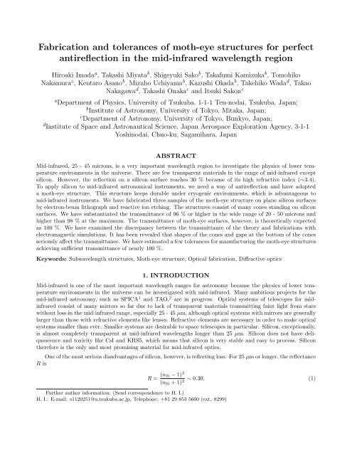
<strong>Fabrication</strong> <strong>and</strong> <strong>tolerances</strong> <strong>of</strong> <strong>moth</strong>-<strong>eye</strong> <strong>structures</strong> <strong>for</strong> <strong>perfect</strong><br />
antireflection in the mid-infrared wavelength region<br />
Hiroaki Imada a , Takashi Miyata b , Shigeyuki Sako b , Takafumi Kamizuka b , Tomohiko<br />
Nakamura c , Kentaro Asano b , Mizuho Uchiyama b , Kazushi Okada b , Takehiko Wada d , Takao<br />
Nakagawa d , Takashi Onaka c <strong>and</strong> Itsuki Sakon c<br />
a Department <strong>of</strong> Physics, University <strong>of</strong> Tsukuba, 1-1-1 Ten-nodai, Tsukuba, Japan;<br />
b Institute <strong>of</strong> Astronomy, University <strong>of</strong> Tokyo, Mitaka, Japan;<br />
c Department <strong>of</strong> Astronomy, University <strong>of</strong> Tokyo, Bunkyo, Japan;<br />
d Institute <strong>of</strong> Space <strong>and</strong> Astronautical Science, Japan Aerospace Exploration Agency, 3-1-1<br />
Yoshinodai, Chuo-ku, Sagamihara, Japan<br />
ABSTRACT<br />
Mid-infrared, 25 - 45 microns, is a very important wavelength region to investigate the physics <strong>of</strong> lower temperature<br />
environments in the universe. There are few transparent materials in the range <strong>of</strong> mid-infrared except<br />
silicon. However, the reflection on a silicon surface reaches 30 % because <strong>of</strong> its high refractive index (∼3.4).<br />
To apply silicon to mid-infrared astronomical instruments, we need a way <strong>of</strong> antireflection <strong>and</strong> have adopted<br />
a <strong>moth</strong>-<strong>eye</strong> structure. This structure keeps durable under cryogenic environments, which is advantageous to<br />
mid-infrared instruments. We have fabricated three samples <strong>of</strong> the <strong>moth</strong>-<strong>eye</strong> structure on plane silicon surfaces<br />
by electron-beam lithograph <strong>and</strong> reactive ion etching. The <strong>structures</strong> consist <strong>of</strong> many cones st<strong>and</strong>ing on silicon<br />
surfaces. We have substantiated the transmittance <strong>of</strong> 96 % or higher in the wide range <strong>of</strong> 20 - 50 microns <strong>and</strong><br />
higher than 98 % at the maximum. The transmittance <strong>of</strong> <strong>moth</strong>-<strong>eye</strong> surfaces, however, is theoretically expected<br />
as 100 %. We have examined the discrepancy between the transmittance <strong>of</strong> the theory <strong>and</strong> fabrications with<br />
electromagnetic simulations. It has been revealed that shapes <strong>of</strong> the cones <strong>and</strong> gaps at the bottom <strong>of</strong> the cones<br />
seriously affect the transmittance. We have estimated a few <strong>tolerances</strong> <strong>for</strong> manufacturing the <strong>moth</strong>-<strong>eye</strong> <strong>structures</strong><br />
achieving sufficient transmittance <strong>of</strong> nearly 100 %.<br />
Keywords: Subwavelength <strong>structures</strong>, Moth-<strong>eye</strong> structure, Optical fabrication, Diffractive optics<br />
1. INTRODUCTION<br />
Mid-infrared is one <strong>of</strong> the most important wavelength ranges <strong>for</strong> astronomy because the physics <strong>of</strong> lower temperature<br />
environments in the universe can be investigated with mid-infrared. Many ambitious projects <strong>for</strong> the<br />
mid-infrared astronomy, such as SPICA 1 <strong>and</strong> TAO, 2 are in progress. Optical systems <strong>of</strong> telescopes <strong>for</strong> midinfrared<br />
consist <strong>of</strong> many mirrors so far due to lack <strong>of</strong> transparent materials transmitting faint light from stars<br />
without loss in the mid-infrared range, especially 25 - 45 µm, although optical systems with mirrors are generally<br />
larger than those with refractive elements like lenses. Refractive elements are necessary in order to make optical<br />
systems smaller than ever. Smaller systems are desirable to space telescopes in particular. Silicon, exceptionally,<br />
is almost completely transparent at mid-infrared wavelengths longer than 25 µm. Silicon does not have deliquescence<br />
<strong>and</strong> toxicity like CsI <strong>and</strong> KRS5, which means that silicon is very stable <strong>and</strong> easy to process. Silicon<br />
there<strong>for</strong>e is the only <strong>and</strong> most promising material <strong>for</strong> mid-infrared optics.<br />
One <strong>of</strong> the most serious disadvantages <strong>of</strong> silicon, however, is reflecting loss. For 25 µm or longer, the reflectance<br />
R is<br />
Further author in<strong>for</strong>mation: (Send correspondence to H. I.)<br />
H. I.: E-mail: s1120251@u.tsukuba.ac.jp, Telephone: +81 29 853 5600 (ext. 8299)<br />
R = (n Si − 1) 2<br />
∼ 0.30, (1)<br />
(n Si + 1)<br />
2
Figure 1. (a) A schematic illustration <strong>of</strong> <strong>moth</strong>-<strong>eye</strong> structure. The transmittance depends on D <strong>and</strong> H. (b) The SEM<br />
image <strong>of</strong> the sample No. 1 taken right above the protuberances. (c) The side image <strong>of</strong> the sample No. 1. The flared<br />
shape is observed. The sample No.2 has a similar shape to that <strong>of</strong> No. 1. (d) The side image <strong>of</strong> the sample No. 3. The<br />
shape <strong>of</strong> the protuberances is straight.<br />
where n Si is the refractive index <strong>of</strong> silicon, <strong>and</strong> n Si ∼ 3.42. 3 This high reflectance arises from its extremely high<br />
refractive index. Antireflection is strongly needed <strong>for</strong> astronomical applications. Although there are many ways<br />
<strong>for</strong> antireflection, most <strong>of</strong> them cannot be applied to mid-infrared instruments. Muti-layer coating, <strong>for</strong> example,<br />
is one <strong>of</strong> the most popular ways to achieve antireflection but needs various kinds <strong>of</strong> materials, each having a<br />
different refractive index. In addition, multi-layer structure can be broken due to bimetal effect under cryogenic<br />
environment which is needed in order to suppress the thermal radiation from instruments. We there<strong>for</strong>e have<br />
difficulty in applying multi-layer coating. Another example is a sub-wavelength structure which consists <strong>of</strong> bulk<br />
<strong>and</strong> porous layers piled by turns. 4 It is suitable <strong>for</strong> antireflection but not easy to fabricate because it is necessary<br />
to pile many layers in order to achieve broadb<strong>and</strong> antireflection. A <strong>moth</strong>-<strong>eye</strong> structure is also one <strong>of</strong> effective<br />
<strong>structures</strong> <strong>for</strong> antireflection. This structure is a surface-relief structure which needs only one material. We think<br />
this structure is the best because it does not have problems mentioned above. We have designed <strong>moth</strong>-<strong>eye</strong><br />
<strong>structures</strong> on silicon <strong>for</strong> 25-40 µm.<br />
The <strong>moth</strong>-<strong>eye</strong> structure has many protuberances placed on a plane surface next to each other like Fig. 1(a).<br />
The protuberances have nearly a conical shape. A similar structure can be found on corneas <strong>of</strong> nocturnal insects,<br />
such as <strong>moth</strong>s, after which it is called <strong>moth</strong>-<strong>eye</strong> structure. Bernhard 5 showed that the <strong>structures</strong> on the corneas<br />
<strong>of</strong> <strong>moth</strong>s worked to suppress reflection by experiments using a model scaled up properly <strong>for</strong> microwave. In case<br />
<strong>of</strong> visible light, they have been applied to a surface on crystalline silicon <strong>for</strong> solar cells (e.g. Forberich et al. 6 ).<br />
Moth-<strong>eye</strong> <strong>structures</strong> on a GaAs substrate have been analyzed in detail in the near-infrared up to 17 µm. 7<br />
In this paper, 25-40 µm is the b<strong>and</strong> in which we would like to attain transmittance <strong>of</strong> more than 99 %<br />
<strong>for</strong> normal incidence. The next section includes how we have determined the design <strong>of</strong> the <strong>moth</strong>-<strong>eye</strong> structure<br />
<strong>and</strong> have fabricated them. In section 3, it is shown how we have made measurements <strong>and</strong> have corrected the<br />
measurements <strong>for</strong> getting precise transmittance. In section 4, the results <strong>of</strong> measurements after analysis are
shown. Simulations with Rigorous Coupled Wave Analysis (RCWA) have been carried out to investigate what<br />
makes the spectra <strong>of</strong> the measurements in section 5. Finally, we summarize a few <strong>tolerances</strong> <strong>for</strong> fabrication <strong>of</strong><br />
<strong>moth</strong>-<strong>eye</strong> <strong>structures</strong>.<br />
2. DESIGN AND FABRICATION OF MOTH-EYE STRUCTURE<br />
The principle <strong>of</strong> antireflection by <strong>moth</strong>-<strong>eye</strong> structure is understood qualitatively well. The essence <strong>of</strong> reflection is<br />
that a refractive index is discontinuous at an interface between two media. If the wavelength λ is longer than the<br />
period D between the protuberances (Fig. 1 (a)), the refractive index appears to be an effective value between<br />
those <strong>of</strong> silicon n Si <strong>and</strong> vacuum. Moreover, if the effective refractive index varies so gradually at the interface<br />
that the light cannot recognize the discontinuity or variation <strong>of</strong> it, reflection should not be generated. Rayleigh 8<br />
investigated the relation between the wavelength λ <strong>and</strong> the effective thickness H <strong>of</strong> the layer <strong>of</strong> graded refractive<br />
index. H corresponds to the height <strong>of</strong> the <strong>moth</strong>-<strong>eye</strong> protuberances. Clapham et al. 9 calculated the reflectance <strong>of</strong><br />
the graded interface <strong>and</strong> showed the results (see fig. 3 in Clapham et al.). When H/λ ≪ 1, the refractive index<br />
appears to be discontinuous <strong>and</strong> the reflectance is not zero. As H/λ increases, the reflectance falls monotonically<br />
<strong>and</strong> reaches 0% at H/λ ∼ 0.4. When H/λ is larger than 0.3, that is, λ < ∼ 3H, the reflectance is less than 1 %.<br />
Diffraction is another concern to design the shape <strong>of</strong> the protuberances. When the wavelength λ is equal<br />
to or shorter than n Si D, the <strong>moth</strong>-<strong>eye</strong> structure acts as a grating <strong>and</strong> the higher orders <strong>of</strong> the transmitted<br />
diffraction are generated, which makes the 0th order diffraction decreased. Detailed <strong>and</strong> strict discussions about<br />
the effective index <strong>of</strong> refraction <strong>and</strong> diffraction can be found in Brückner et al. 10 In the consideration above,<br />
approximately n Si D < λ < 3H is the range in which the transmittance <strong>of</strong> the 0th order diffraction is almost 100<br />
% theoretically.<br />
We have designed <strong>moth</strong>-<strong>eye</strong> <strong>structures</strong> to attain transmittance <strong>of</strong> more than 99% in the wavelengths from 25<br />
µm to 40 µm. For normal incidence, one <strong>of</strong> the limits <strong>of</strong> the transmitted wavelength is given by n Si D ≤ 25 µm,<br />
which yields D ≤ 7.3 µm. The other is 40µm ≤ 3H, that is, H ≥ 13.3 µm. We have adopted D = 5 µm <strong>and</strong><br />
H =15 - 20 µm as a goal in fabricating.<br />
The shape <strong>of</strong> protuberances we have intended to fabricate is a cone, which is easier to process. The substrates<br />
are high resistivity silicon, the diameter is 4 inches <strong>and</strong> the thickness is 600 µm. One side <strong>of</strong> the substrates was<br />
processed <strong>and</strong> the other side was not. Electron-beam lithograph <strong>and</strong> Reactive Ion Etching (RIE) was used. The<br />
first process was to make metal masks by electron-beam lithograph on the silicon surface where the protuberances<br />
should st<strong>and</strong>. Then, a silicon surface was etched by optimizing ion energies <strong>of</strong> reactive ions. As a result, the<br />
area without the metal masks was carved, then protuberances like cones appeared on the surface <strong>of</strong> the silicon.<br />
Finally, the metal masks were removed.<br />
We have acquired three <strong>moth</strong>-<strong>eye</strong> samples. The diameter <strong>of</strong> the processed area <strong>of</strong> No.1 <strong>and</strong> No.2 is 25mm, <strong>and</strong><br />
that <strong>of</strong> No. 3 is 40mm. Fig. 1 (b) is a scanning electron microscope (SEM) image taken right above protuberances.<br />
The period D <strong>and</strong> the height H <strong>of</strong> all the samples were measured as 5 µm <strong>and</strong> 16 µm, respectively. Fig. 1 (c)<br />
<strong>and</strong> Fig. 1 (d) <strong>of</strong> SEM images show the side views <strong>of</strong> the protuberances. There is a difference in the shape<br />
<strong>of</strong> the cones among the samples. The samples No.1 <strong>and</strong> No.2 have flared shape: they have spindly tops <strong>and</strong><br />
become fat as getting close to the bottom (Fig. 1 (c)). By contrast, No. 3 is straight shapes from the tops to<br />
the bottoms (Fig. 1 (d)). Note that the tops <strong>of</strong> the protuberances remain flat, not pointed, due to the metal<br />
masks in processing. Fig. 2 was a photo taken in visible light. The area with <strong>moth</strong>-<strong>eye</strong> structure seems to have<br />
no reflection in visible light range <strong>and</strong> the other area looks like a mirror.<br />
3. MEASUREMENT AND ANALYSIS<br />
Transmittance spectra <strong>of</strong> the samples were obtained by Fourier Trans<strong>for</strong>m Infrared spectroscopy (FT-IR). The<br />
incident angle was 0 degrees. The 0th order transmitted diffraction was measured in a vacuum. The mylar beam<br />
splitter was used. The samples were at the room temperature around 300 K. The resolution was 2 cm −1 . For<br />
getting better S/N, we have averaged 6 successive measurement points relative to wavenumbers, there<strong>for</strong>e the<br />
effective resolution was 12 cm −1 .
Figure 2. The appearance <strong>of</strong> No.3. The <strong>moth</strong>-<strong>eye</strong> structure is in the central area <strong>and</strong> there seems to be no reflection, whereas<br />
the area without <strong>moth</strong>-<strong>eye</strong> structure reflects visible light like a mirror. The yellow crosses represent the measurement<br />
points. The intervals between two points were 10 mm <strong>for</strong> No. 3.<br />
The measurements must be corrected <strong>for</strong> getting precise transmittance spectra because one side <strong>of</strong> the substrates<br />
remains bare <strong>and</strong> the absorption <strong>of</strong> the silicon is not completely negligible. For this purpose, we have<br />
measured spectra on several parts <strong>of</strong> the silicon with <strong>and</strong> without the <strong>moth</strong>-<strong>eye</strong> structure (Fig. 2).<br />
First, we have estimate absorption <strong>of</strong> a sample. The measurable transmittance <strong>of</strong> a bare silicon board T Si is<br />
given by<br />
T Si = (1 − R) 2 exp(−κd)<br />
∞∑<br />
[R exp(−κd)] 2m , (2)<br />
where R = (n Si − 1) 2 /(n Si + 1) 2 is the reflectance on a bare silicon surface in a vacuum, κ is the absorption<br />
coefficient <strong>of</strong> the sample <strong>and</strong> d is the thickness <strong>of</strong> it. n Si is the refractive index <strong>of</strong> silicon. We have used Edwards’<br />
data 3 <strong>for</strong> the refractive index n Si <strong>and</strong> the data is reproduced by<br />
m=0<br />
n Si (λ) = 3.41861 + 0.02661 + 2.6939 × 10 −5 λ − 2.6405 × 10 −7 λ 2<br />
λ<br />
− 1.6729 × 10 −9 λ 3 + 1.2612 × 10 −11 λ 4 , (3)<br />
where the unit <strong>of</strong> λ is µm. In the range <strong>of</strong> 10µm - 70µm, equation (3) replicates Edwards’ data well (Fig. 3 (a)).<br />
We can solve equation (2) <strong>for</strong> the unknown variable κ.<br />
Second, we have calculated the transmittance on a surface with the <strong>moth</strong>-<strong>eye</strong> structure using the absorption<br />
coefficient κ solved in advance. If there is no absorption on the surface with <strong>moth</strong>-<strong>eye</strong>, the measurable<br />
transmittance T is<br />
T = (1 − R ME )(1 − R) exp(−κd)<br />
∞∑<br />
[R ME R exp(−2κd)] m , (4)<br />
where R ME is the reflectance on the surface with <strong>moth</strong>-<strong>eye</strong>. By solving equation (4) <strong>for</strong> R ME , the transmittance<br />
m=0
Figure 3. (a) The refractive index <strong>of</strong> Edwards’ data <strong>and</strong> its approximation. In the range <strong>of</strong> 10 - 70 µm, equation (3)<br />
replicates Edwards’ data well. (b) The transmittance <strong>of</strong> the samples. It is extremely improved.<br />
at the surface with <strong>moth</strong>-<strong>eye</strong> T ME is obtained,<br />
Equation (5) was used in the analysis <strong>of</strong> all measurements.<br />
T ME = 1 − R ME<br />
T [1 − R exp(−2κd)]<br />
=<br />
(1 − R) exp(−κd) − T R exp(−2κd) . (5)<br />
4. RESULTS<br />
Fig. 3 (b) displays the results <strong>of</strong> the transmittance spectra <strong>of</strong> the <strong>moth</strong>-<strong>eye</strong> structure samples after the correction<br />
with equation (5). The spectra <strong>of</strong> any sample do not depend on the measurement points, so that we show the<br />
spectra at the center <strong>of</strong> every sample. Fig. 3 (b) clearly shows that the <strong>moth</strong>-<strong>eye</strong> structure extremely improved<br />
the transmittance <strong>of</strong> all samples. The best sample is No.3 which has the straight shape. No. 3 achieves more<br />
than 98 % at the maximum <strong>and</strong> more than 96 % in the wide range <strong>of</strong> 20-50 µm. For No.1 <strong>and</strong> No.2 which have<br />
the flared shape, their transmittance is also more than 98 % at the maximum but their pr<strong>of</strong>iles are different from<br />
that <strong>of</strong> No.3. Both the transmittance <strong>of</strong> No.1 <strong>and</strong> No.2 are decreasing rapidly as wavelength gets longer. Their<br />
spectra seem similar but are not completely identical. Note that several peaks around 14, 15, 16, 23 <strong>and</strong> 26 µm<br />
are artificial. These peaks were due to the absorption in FT-IR.<br />
5. SIMULATIONS<br />
The measured transmittance <strong>of</strong> more than 98 % is very high, but it falls short <strong>of</strong> the theoretical expectation<br />
<strong>of</strong> more than 99 %. The shape <strong>of</strong> the protuberances could not make the transmittance reach to 99 %. To<br />
investigate qualitatively how far the shape affects the transmittance, we carried out a numerical analysis with<br />
RCWA. Models <strong>of</strong> the protuberances used in this calculation were based on the fabricated samples; the height<br />
<strong>and</strong> period <strong>of</strong> models was 16 µm <strong>and</strong> 5 µm, respectively.<br />
5.1 Flared model<br />
An ideal <strong>moth</strong>-<strong>eye</strong> structure is illustrated in Fig. 1 (a). The protuberances are <strong>perfect</strong> cones <strong>and</strong> next to each<br />
other. A flared model corresponding to the samples No.1 <strong>and</strong> No.2 is shown in Fig. 4 (a). The simulated spectra<br />
<strong>of</strong> the ideal model <strong>and</strong> flared model are Fig. 4 (b); the solid line (red) represents the ideal model, the longest<br />
dashed line (green) is the model <strong>for</strong> No.1 <strong>and</strong> No.2, the second longest (blue) is the measurement <strong>of</strong> No. 2, <strong>and</strong><br />
the shortest (magenta) is the measurement <strong>of</strong> No.3. We can see that the models approximately reproduce the
Figure 4. (a) A flared model <strong>for</strong> No.1 <strong>and</strong> No.2. (b) The results <strong>of</strong> simulation <strong>and</strong> measurements. The solid line (red)<br />
is <strong>for</strong> the ideal cone model <strong>and</strong> the longest dashed line (green) <strong>for</strong> the flared cone model. The second longest dashed<br />
line (blue) represents the measurement <strong>of</strong> No.2 <strong>and</strong> the shortest (mazenta) represents the measurement <strong>of</strong> No. 3. The<br />
simulation reproduces the measurements well.<br />
Figure 5. (a) A flat top model. (b) The result <strong>of</strong> simulation as a function <strong>of</strong> the filling factor. The solid line (red)<br />
corresponds to 30 µm <strong>and</strong> the dashed line (green) 40 µm.
Figure 6. (a) A model <strong>of</strong> straight shape cones having gap space between protuberances at the bottom. (b) The result <strong>of</strong><br />
simulation as a function <strong>of</strong> the porosity. The solid line (red) corresponds to 30 µm <strong>and</strong> the dashed line (green) corresponds<br />
to 40 µm.<br />
transmittance <strong>of</strong> No.2 <strong>and</strong> No.3, respectively. We deduced that the rapid decrease <strong>of</strong> the transmittance <strong>of</strong> No.1<br />
<strong>and</strong> No. 2 at longer wavelengths is caused by the flared shape. This is qualitatively explained as follows: the<br />
protuberances are so spindly that the effective index <strong>of</strong> refraction is almost 1 near the tops, whereas the index<br />
rapidly increases near the foot because <strong>of</strong> the flared shape. The effective height <strong>of</strong> the protuberances there<strong>for</strong>e<br />
becomes lower than the actual height. This causes the decrease <strong>of</strong> the transmittance at longer wavelengths.<br />
5.2 Flat top model<br />
We have taken notice <strong>of</strong> effects <strong>of</strong> the flat tops shown in Fig. 5 (a). The size <strong>of</strong> the flat area is a parameter <strong>of</strong><br />
this model. To assess it, a filling factor at the top is introduced as a ratio <strong>of</strong> the flat area to the area <strong>of</strong> one<br />
section surrounded by the black lines in Fig. 1 (b). Fig. 5 (b) shows the relation between the filling factor <strong>and</strong><br />
the transmittance at 30 µm (solid line, red) <strong>and</strong> 40 µm (dashed line, green). The filling factor <strong>of</strong> 3 %, which<br />
is estimated from the SEM image (Fig. 1 (b)), corresponds to the transmittance <strong>of</strong> more than 99.5 % at both<br />
30 <strong>and</strong> 40 µm. The transmittance does not become 98 % unless the filling factor exceeds ∼20 %, not observed<br />
in the SEM images. The flat tops can hardly affect the transmittance in our measurements, that is, the filling<br />
factor <strong>of</strong> a few percent allows the transmittance to reach more than 99 %.<br />
5.3 Gap space model<br />
We have tried models with gap space at the bottom between the cone. The model we have made is shown in<br />
Fig. 6 (a) <strong>and</strong> the result is in Fig. 6 (b). To assess the size <strong>of</strong> gap space, a porosity at the bottom is defined as<br />
a ratio <strong>of</strong> the area <strong>of</strong> gap space to that <strong>of</strong> the section. The porosity corresponding to the transmittance <strong>of</strong> 98 %<br />
is about 23 %, which is realized when the diameter <strong>of</strong> the protuberances at the bottom is 4.6 µm. It is probable<br />
that there are gaps <strong>of</strong> 0.4 µm between the cones at the bottom as far as we have observed the SEM images.<br />
Thus we conclude that the shortage <strong>of</strong> the transmittance is caused by the gaps at the bottom rather than by the<br />
flat tops. To achieve 99 %, it is important that the porosity is less than 15 %.<br />
The differences between the spectra No.1 <strong>and</strong> No.2 can also be attributed to this gap effect. We have calculated<br />
the flared model with <strong>and</strong> without gaps at the bottom. The result is shown in Fig. 7. The transmittance <strong>of</strong> the<br />
gap model also decreases more rapidly than the no-gap model.<br />
6. CONCLUSION<br />
We have developed antireflection <strong>for</strong> mid-infrared astronomical instruments with <strong>moth</strong>-<strong>eye</strong> <strong>structures</strong>. Electronbeam<br />
lithograph <strong>and</strong> RIE was used to fabricate the <strong>moth</strong>-<strong>eye</strong> <strong>structures</strong> on silicon. We have obtained three<br />
samples which have different shapes <strong>of</strong> the protuberances. The pr<strong>of</strong>iles <strong>of</strong> the transmittance are also different.
transmittance [%]<br />
110<br />
100<br />
90<br />
80<br />
no gap space<br />
gap space<br />
No. 1<br />
No. 2<br />
70<br />
65<br />
10 20 30 40 50 60 70<br />
wavelength [µm]<br />
Figure 7. The result <strong>of</strong> simulation <strong>for</strong> flared models with <strong>and</strong> without gap space. The solid line (red) corresponds to the<br />
case without gap <strong>and</strong> the longest dashed line (green) with gap. The second longest (blue) represents the measurement <strong>of</strong><br />
No. 1 <strong>and</strong> the shortest (magenta) represents the measurement <strong>of</strong> No.2.<br />
The best sample has transmitted more than 98 % at the maximum <strong>and</strong> more than 96 % in the wide range <strong>of</strong><br />
20-50 µm. To investigate what made the spectra different, <strong>and</strong> why the transmittance did not reach more than<br />
99 % in the wide range, we have carried out a numerical analysis with RCWA. Consequently, we have acquired<br />
a few <strong>tolerances</strong> <strong>for</strong> fabricating <strong>moth</strong>-<strong>eye</strong> <strong>structures</strong>:<br />
1. The shape <strong>of</strong> the protuberances must be straight from the tops to the bottoms.<br />
2. The tops may be flat if the filling factor is a few percent.<br />
3. Gap space at the bottom must be as little as possible, that is, the porosity is less than 15 %.<br />
If the <strong>moth</strong>-<strong>eye</strong> structure can be made within the allowed <strong>tolerances</strong>, the transmittance <strong>of</strong> more than 99 % will<br />
be achieved.<br />
In the near future, <strong>moth</strong>-<strong>eye</strong> <strong>structures</strong> will be applied to both sides <strong>of</strong> silicon substrates <strong>and</strong> finally to silicon<br />
lens <strong>for</strong> mid-infrared instruments.<br />
ACKNOWLEDGMENTS<br />
We are grateful to NTT Advanced Technology Corporation <strong>for</strong> fabricating the <strong>moth</strong>-<strong>eye</strong> structure samples which<br />
meet our requirements. This work was supported by Grant-in-Aid <strong>for</strong> Young Scientists (A) 21740131 <strong>and</strong> Grant<br />
<strong>for</strong> development <strong>of</strong> on-board instruments from JAXA.<br />
REFERENCES<br />
[1] Nakagawa, T., “The next-generation space infrared astronomy mission SPICA,” in [Space Telescopes <strong>and</strong><br />
Instrumentation 2010: Optical, Infrared, <strong>and</strong> Millimeter Wave], Oschmann, J. M. J., Clampin, M. C., <strong>and</strong><br />
MacEwen, H. A., eds., Proc. SPIE 7731, 77310O–77310O–8 (2010).<br />
[2] Yoshii, Y., Aoki, T., Doi, M., H<strong>and</strong>a, T., Kawara, K., Kato, D., Kohno, K., Konishi, M., Koshida, S.,<br />
Minezaki, T., Mitani, N., Miyata, T., Motohara, K., Sako, S., Soyano, T., Tanabe, T., Tanaka, M., Tarusawa,<br />
K., Bronfman, L., Ruiz, M. T., <strong>and</strong> Hamuy, M., “The University <strong>of</strong> Tokyo Atacama Observatory 6.5m<br />
telescope project,” in [Ground-based <strong>and</strong> Airborne Telescopes III], Stepp, L. M., Gilmozzi, R., <strong>and</strong> Hall,<br />
H. J., eds., Proc. SPIE 7733, 773308–773308–9 (2010).<br />
[3] Edwards, D., “Silicon (Si),” in [H<strong>and</strong>book <strong>of</strong> Optical Constants od Solids], Palik, E., ed., 547–569, Academic<br />
Press (1985).
[4] Wada, T., Makitsubo, H., <strong>and</strong> Mita, M., “Mono-Material Multilayer Interference Optical Filter with Sub-<br />
Wavelength Structure <strong>for</strong> Infrared <strong>and</strong> Terahertz Optics,” Applied Physics Express 3(10), 102503–102503–3<br />
(2010).<br />
[5] Bernhard, G., “Structural <strong>and</strong> functional adaptation in a visual system,” Endeavour 26, 79 (1967).<br />
[6] Forberich, K., Dennler, G., Scharber, M., Hingerl, K., Fromherz, T., <strong>and</strong> Brabec, C., “Per<strong>for</strong>mance improvement<br />
<strong>of</strong> organic solar cells with <strong>moth</strong> <strong>eye</strong> anti-reflection coating,” Thin Solid Films 516, 7167–7170<br />
(2008).<br />
[7] Raguin, D. H. <strong>and</strong> Morris, G. M., “Antireflection structured surfaces <strong>for</strong> the infrared spectral region,”<br />
Applied Optics 32, 1154–1167 (1993).<br />
[8] Lord Rayleigh, “On Reflection <strong>of</strong> Vibrations at the Confines <strong>of</strong> two media between which the Transition is<br />
gradual,” Proc. Lond. Math. Soc. 11, 51 (1880).<br />
[9] Clapham, P. B., “Reduction <strong>of</strong> Lens Reflexion by the “Moth Eye” Principle,” Nature 244, 281 (1973).<br />
[10] Brückner, C., Käsebier, T., Pradarutti, B., Riehemann, S., Notni, G., Kley, E.-B., <strong>and</strong> Tünnermann, A.,<br />
“Broadb<strong>and</strong> antireflective <strong>structures</strong> applied to high resistive float zone silicon in the THz spectral range,”<br />
Opt. Express 17(5), 3063–3077 (2009).