Heraeus Noblelight Flashlamp..
Heraeus Noblelight Flashlamp..
Heraeus Noblelight Flashlamp..

Create successful ePaper yourself
Turn your PDF publications into a flip-book with our unique Google optimized e-Paper software.
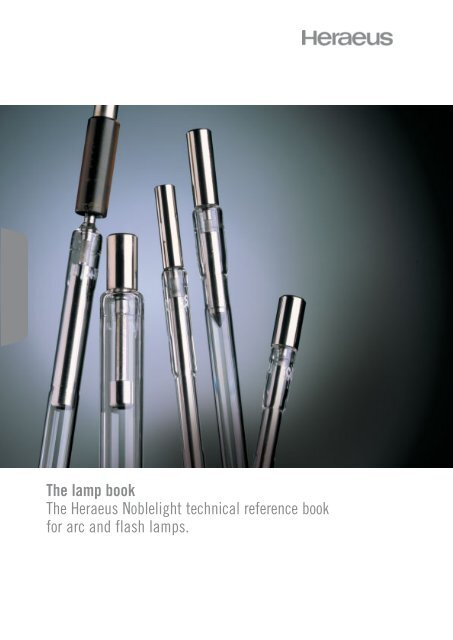
The lamp book<br />
The <strong>Heraeus</strong> <strong>Noblelight</strong> technical reference book<br />
for arc and flash lamps.
”<strong>Heraeus</strong> <strong>Noblelight</strong> has always been known for<br />
quality lamps. Today, as the importance<br />
of support grows for laser manufacturers,<br />
an excellent standard in customer service has<br />
become part of our quality philosophy.“
Laser excitation lamps in a new light<br />
<strong>Noblelight</strong> was founded by John Littlechild in 1976<br />
based on the premise that innovation can only be<br />
driven by close collaboration with the customer.<br />
We pioneered laser lamp manufacturing and electrode<br />
technology including the HI-CHARGE Cathode ® .<br />
Since 1986, <strong>Noblelight</strong> has been part of the <strong>Heraeus</strong><br />
group with access to advanced lamp manufacturing<br />
technology and quartz glass expertise.<br />
Today, <strong>Heraeus</strong> <strong>Noblelight</strong> Ltd. not only has the most<br />
advanced automated laser lamp manufacturing line,<br />
but also keeps exploring new ways to improve lamp<br />
performance with research institutes and, most<br />
importantly, our customers. We invest in enlarging our<br />
production capacity as more and more customers<br />
turn to us for high quality products and professional<br />
service. Applications of our products include not just<br />
laser technology, but also areas like cosmetics and<br />
Rapid Thermal Processing of silicon wafers.<br />
We provide close personal service to laser system<br />
manufacturers and users. Our experienced team of<br />
engineers and customer service experts will assist<br />
you from consultancy and design through to on-time<br />
delivery from our in-house manufacturing in<br />
Cambridge.<br />
<strong>Heraeus</strong> <strong>Noblelight</strong> has<br />
produced this technical<br />
reference book as a guide to<br />
designers, as there are key<br />
construction aspects which<br />
warrant careful consideration<br />
when designing a lamp.<br />
This book follows the same<br />
information sequence as the<br />
technical data sheet (see page<br />
39) which provides <strong>Heraeus</strong><br />
<strong>Noblelight</strong>’s R&D team with the<br />
necessary information to design<br />
lamps to match customer needs<br />
precisely.<br />
As you fill in each section of the<br />
form, please read the<br />
corresponding section in the<br />
book.<br />
The R&D team at <strong>Heraeus</strong><br />
<strong>Noblelight</strong> is poised to help with<br />
any questions you may have.<br />
Please contact:<br />
(+44) 1223 423324.
The lamp book<br />
The <strong>Heraeus</strong> <strong>Noblelight</strong> technical<br />
Lamp seals 6<br />
Solder, Ribbon, and Rod Seals 6<br />
Electrodes 7<br />
The anode 7<br />
The cathode 7<br />
Cathode types 7<br />
Gas fill and pressure 10<br />
Pulsed lamps 10<br />
Continuous Wave lamps 11<br />
Envelope materials 13<br />
Quartz types 13<br />
Power calculations 14<br />
Tolerances 15<br />
Lamp Triggering 16<br />
Series triggering 16<br />
Parallel triggering 17<br />
External triggering 17<br />
Continuous lamp operation 18<br />
Operation 18<br />
CW lamp design parameters 19<br />
Pulsed lamp operation 21<br />
Pulse forming network operation 21<br />
Current curves 23<br />
Square Wave operation 24
eference book.<br />
5<br />
Lamp cooling 28<br />
Convection air cooling 28<br />
Forced air cooling 28<br />
Fluid cooling 28<br />
Lamp finishing and terminations 30<br />
Materials 30<br />
Positioning 30<br />
Lamp mounting 30<br />
Trigger wires 30<br />
Lamp lifetime 31<br />
Failure mechanisms 31<br />
Electrode erosion 31<br />
Gas fill contamination 32<br />
Glass to metal seal failure 32<br />
Envelope ageing 33<br />
Lifetime calculations 33<br />
Glossary 34<br />
Lamp coding 35<br />
Lamp assembly 35<br />
Lamp formulae 36<br />
Conversion factors 37<br />
Technical data sheet 39<br />
Contents
6<br />
Lamp seals<br />
Lamp seals 6<br />
Electrodes 7<br />
Gas fill and pressure 10<br />
Envelope materials 13<br />
Lamp triggering 16<br />
Continuous lamp operation 18<br />
Pulsed lamp operation 21<br />
Lamp cooling 28<br />
Lamp finishing/terminations 30<br />
Lamp lifetime 31<br />
Glossary 34<br />
Lamp coding 35<br />
Lamp assembly 35<br />
Lamp formulae 36<br />
Conversion factors 37<br />
Technical data sheet 39<br />
Electrode body<br />
In order to achieve the necessary<br />
hermetic structure, there are three main<br />
sealing techniques used in arc lamp<br />
manufacture – ribbon seal, solder seal<br />
and rod seal.<br />
Solder Seal<br />
The Solder Seal or End Cap Seal (figure<br />
1) is created by soldering a circular Invar<br />
band around the end of a quartz tube.<br />
The lamp can be designed with a small<br />
dead space and a coolant channel within<br />
the electrodes. Because of the low<br />
melting point of the Lead Indium solder,<br />
however, the operating temperature must<br />
be limited to around 100°C.<br />
These lamps cannot be used in high<br />
average power applications. The use of<br />
high temperature processing during<br />
manufacture is also prevented, thus<br />
lamps with this sealing technique tend to<br />
have a shorter life than those with<br />
alternative seals.<br />
Ribbon Seal<br />
The Ribbon Seal (figure 2) is formed by<br />
shrinking quartz directly onto a thin foil of<br />
Molybdenum. This thin foil is necessary<br />
Fig.1 Solder Seal<br />
Fig.2 Ribbon Seal<br />
Molybdenum ribbon<br />
to prevent the seal cracking due to<br />
unequal expansion rates between<br />
Molybdenum and quartz.<br />
This seal produces a very rugged lamp<br />
with no dead space, but its peak and<br />
RMS current are limited (max. RMS<br />
current ~20Amps).<br />
Rod Seal<br />
The Rod Seal (figure 3) is by far the most<br />
commonly used of the lamp seals. It is<br />
created by wetting a sealing glass directly<br />
onto the unoxidised surface of a<br />
Tungsten wire, hence it is also called<br />
Bright Seal.<br />
This sealing technique allows for high<br />
temperature and high vacuum processing<br />
during manufacture, ensuring a lamp that<br />
has the performance and reliability<br />
demanded by today’s customers. The<br />
seal can withstand long-term operating<br />
temperatures up to 250°C and 600°C for<br />
short periods, and can also withstand<br />
high peak and RMS currents.<br />
The Rod Seal has become the industry<br />
standard for high performance,<br />
continuous and pulsed arc lamps.<br />
Quartz envelope TIG-weld joint Anode cooling channel<br />
Lead-Indium<br />
solder<br />
Invar<br />
band<br />
Anode coolant<br />
exit hole<br />
Tungsten rod<br />
Fig.3 Rod Seal<br />
Quartz tube<br />
Electrode body<br />
Sealing glass
Electrodes<br />
7<br />
In the lamp, the transformation of<br />
electrical energy into a light emitting<br />
plasma takes place at the electrodes.<br />
For the electrode design to be<br />
considered effective, this transfer must<br />
be efficient, and the resultant arc must be<br />
reliably controlled for maximum lamp life<br />
and system performance. With this in<br />
mind, the importance of the electrode<br />
should not be overlooked.<br />
The anode<br />
The simplest of the electrodes is the<br />
anode, made of high purity Tungsten<br />
doped with a rare earth oxide. The<br />
dopant aids the machining of the<br />
electrode which would otherwise be<br />
difficult (pure Tungsten is very brittle). The<br />
anode’s primary purpose is to receive the<br />
charge emitted by the cathode and<br />
hence complete the electrical circuit.<br />
Care should be taken when considering<br />
shape. The anode must have a large tip<br />
area that is in proportion to the power it<br />
receives. It should also have a shape that<br />
holds the arc in the centre of the lamp’s<br />
bore at all times. Where the arc is<br />
allowed to drift close to the quartz, an<br />
excessive thermal loading is caused<br />
which rapidly ages the quartz and<br />
consequently reduces the lamp’s life.<br />
The cathode<br />
Like the anode, the main body of the<br />
cathode is manufactured from doped<br />
Tungsten, however a separate tip is<br />
brazed onto the main body of the<br />
electrode. While this tip only forms a<br />
small part of the lamp’s construction, it is<br />
arguably one of the most important<br />
features of the lamp.<br />
The tip of the cathode is made of porous<br />
Tungsten. This porosity is tightly<br />
controlled during the manufacturing<br />
process, when the loose powder is<br />
compressed, under massive pressures,<br />
to form the tip.<br />
At the time of writing, <strong>Heraeus</strong> <strong>Noblelight</strong><br />
is the only laser lamp manufacturer to<br />
carry out this process in-house, where it<br />
is controlled to a precise degree. The<br />
porous Tungsten matrix is then<br />
impregnated with a dopant, again to a<br />
defined level.<br />
The dopant is a proprietary powder<br />
having a low work function, to ease the<br />
emission of electrons and reduce the<br />
temperature for an extended cathode<br />
lifetime. Depending on the lamp’s<br />
application, the level of doping used<br />
needs careful consideration - Engineers<br />
at <strong>Heraeus</strong> <strong>Noblelight</strong> can advise on this.<br />
For instance, in the case of a continuous<br />
wave (CW) lamp, there is a high<br />
concentration of dopant on the surface of<br />
the cathode to aid the lamp’s operation.<br />
Yet in the case of pulse lamps where<br />
there is a high peak current and a long<br />
pulse, the amount of emissive material on<br />
the surface of the cathode should be<br />
limited.<br />
Providing consideration is given to the<br />
above, cathode break-up is reduced,<br />
thus increasing the lamps’ life.<br />
The Hi-Charge cathode<br />
<strong>Heraeus</strong> <strong>Noblelight</strong>’s patented High<br />
Charge Transfer design (figure 6)<br />
represents an exclusive development in<br />
cathode technology that today remains<br />
unrivalled in the lamp industry.<br />
This innovative technology allows<br />
<strong>Heraeus</strong> <strong>Noblelight</strong> Design Engineers to<br />
fine-tune the temperature of the emitting<br />
surface of a cathode for optimum<br />
performance. Figure 4 demonstrates the<br />
increased lifetime over competitors’<br />
lamps in relation to charge transfer.
Charge Transfer (Coulombs per pulse)<br />
8<br />
Electrodes continued<br />
Lamp seals 6<br />
Electrodes 7<br />
Gas fill and pressure 10<br />
Envelope materials 13<br />
Lamp triggering 16<br />
Continuous lamp operation 18<br />
Pulsed lamp operation 21<br />
Lamp cooling 28<br />
Lamp finishing/terminations 30<br />
Lamp lifetime 31<br />
Glossary 34<br />
Lamp coding 35<br />
Lamp assembly 35<br />
Lamp formulae 36<br />
Conversion factors 37<br />
Technical data sheet 39<br />
Lamps which are operated using a<br />
square wave pulsed power supply can<br />
be prone to premature ageing because of<br />
thermal cycling in the cathode tip. This<br />
occurs due to the relatively long time<br />
periods between the high power pulses.<br />
The Hi-Charge design developed by<br />
<strong>Heraeus</strong> <strong>Noblelight</strong> limits thermal cycling<br />
and the associated ageing by<br />
incorporating a thermal choke in the neck<br />
of the cathode. This restricts thermal<br />
energy flow out of the cathode between<br />
pulses and stabilises the operating<br />
temperature.<br />
By varying the width of the cathode neck,<br />
the operating temperature of the cathode<br />
can be moved through a range until an<br />
optimum is achieved. Figures 4 and 5<br />
demonstrate the difference between a<br />
<strong>Heraeus</strong> <strong>Noblelight</strong> lamp and the industry<br />
standard when a square wave pulse is<br />
applied.<br />
Figure 5 illustrates the lower fluctuation in<br />
temperature of the <strong>Heraeus</strong> cathode. The<br />
operating temperature of the<br />
Hi-Charge cathode can be raised or<br />
lowered by manufacturing the cathode<br />
neck with different diameters.<br />
The Standard Pulse cathode<br />
In simple terms the Standard Pulse<br />
cathode is a Hi-Charge cathode<br />
without the thermal choke (figure 7). In<br />
practice however, the manufacturing<br />
processes are slightly different to<br />
Fig.4 Lamp lifespans<br />
optimise performance.<br />
This cathode has been developed<br />
specifically for use in systems using a<br />
Pulse Forming Network (PFN) power<br />
supply. The design of this supply differs<br />
from that of a square wave unit. Instead<br />
of using high power electronics to<br />
manipulate the power waveform, a bank<br />
of capacitors and inductors is charged<br />
and then discharged through the lamp to<br />
form the pulse.<br />
PFN power supplies generally deliver<br />
pulses of a lower power than those in a<br />
square wave unit, the pulses having a<br />
curved waveform (half sinusoidal) rather<br />
than a square shape. The exact shape of<br />
the pulse depends upon the damping<br />
( ∝ ) of the circuit as detailed in the Pulse<br />
section (see page 21).<br />
As well as having lower power, the pulses<br />
generated by a PFN network tend to be<br />
shorter, with pulse widths measured in<br />
the microsecond range rather than in<br />
milliseconds. Where lower power, high<br />
frequency, short pulses are applied to the<br />
lamp, the thermal loading per pulse is<br />
considerably less than would be seen in<br />
a Hi-Charge application, thus the<br />
change in cathode temperature between<br />
pulses is much less.<br />
The strain on the cathode material<br />
caused by temperature oscillation is thus<br />
considerably reduced and the use of a<br />
thermal choke is unnecessary.<br />
Fig.5 Temperature fluctuation<br />
4<br />
3<br />
Average of<br />
Industry<br />
<strong>Heraeus</strong> <strong>Noblelight</strong><br />
temperature stabilised<br />
cathode lamps<br />
ΔT<br />
HNL<br />
<strong>Heraeus</strong><br />
2<br />
1<br />
ΔT<br />
standard<br />
Industry standard<br />
4<br />
10<br />
10 5 10 6 10 7 10 8<br />
Life (Pulses)<br />
Lamp<br />
Pulse<br />
Simmer Operation<br />
Time
9<br />
The Air-Cooled cathode<br />
This cathode (figure 8) is a derivative of<br />
the Standard Pulse cathode. Lamps used<br />
in low power applications, where the rise<br />
in temperature of the lamp during<br />
operation remains minimal, require little or<br />
no cooling other than local airflow. The<br />
use of a large Tungsten mount to provide<br />
a sink transferring heat away from the<br />
cathode tip is therefore unnecessary, as<br />
normal thermal radiation through the<br />
quartz body will keep the electrode<br />
temperature at an acceptable level.<br />
Put simply, in the case of an air-cooled<br />
lamp, the mount is completely omitted<br />
and the tip is brazed onto the Tungsten<br />
wire.<br />
The Continuous Wave (CW)<br />
cathode<br />
Until recently the term ‘CW’ referred to<br />
lamps operating at pre-set current values<br />
with either no, or very low frequency<br />
changes to that value. It is hardly<br />
surprising therefore, that just one type of<br />
cathode was used.<br />
More recently this situation has changed.<br />
Now a number of different running<br />
parameters exist which fall under the<br />
label of CW operation (see page 18).<br />
<strong>Heraeus</strong> <strong>Noblelight</strong> has risen to the<br />
challenge of these new operating<br />
parameters by developing a number of<br />
different cathodes in response to market<br />
demands. The cathode in figure 9 is the<br />
standard CW design for applications<br />
where the lamp current trace remains flat,<br />
with little or no change during operation.<br />
This design effectively retains the arc in<br />
the centre of the lamp bore during<br />
operation. The angle of the cathode has<br />
also been specifically engineered so that,<br />
during operation, the tip remains at the<br />
optimum temperature for efficient<br />
emission and maximum life.<br />
A variation on this cathode is illustrated in<br />
figure 10. This has been developed for<br />
quasi-CW operation as described on<br />
page 19. The key difference between the<br />
two cathodes is the quasi-CW cathode’s<br />
rounded end.<br />
The rounded end design was developed<br />
in response to a tendency for the tip end<br />
to form a ball of molten metal and detach<br />
when a standard CW cathode was used<br />
in quasi operation. The rounded tip<br />
design spreads the heat load during<br />
operation, and thus prevents a ball of<br />
molten metal forming.<br />
In the case of modulated CW operation,<br />
as described on page 19 the cathode<br />
design is significantly different to the<br />
models outlined overleaf. This cathode,<br />
(figure 11) is the result of considerable<br />
research and development by <strong>Heraeus</strong><br />
<strong>Noblelight</strong> and leads to a significant<br />
increase in lamp lifetime.<br />
One major problem with modulated CW<br />
operation is the tendency of the arc to<br />
wander around the tip circumference<br />
when the lamp is in the low current<br />
section of its operation cycle. This results<br />
in the quartz immediately next to the<br />
electrode suffering very high thermal<br />
loading, causing rapid ageing.<br />
This cathode design largely prevents this<br />
happening. The shape prevents the arc<br />
from wandering and because the tip is<br />
relatively far away from the quartz, it<br />
dramatically reduces any possibility of<br />
damage.<br />
Fig.6 Hi-Charge cathode<br />
Mount<br />
Mount<br />
Mount<br />
Neck<br />
Tip<br />
Tip<br />
Head<br />
Fig.7 Standard Pulse<br />
cathode<br />
Tip<br />
Fig.8 Air-Cooled cathode<br />
Fig.9 Continuous Wave<br />
(CW) cathode<br />
Tip<br />
Fig.10 Quasi-CW<br />
cathode<br />
Mount<br />
Tip<br />
Fig.11 Modulated CW<br />
cathode<br />
Mount<br />
Tip
10<br />
Gas fill and pressure<br />
Lamp seals 6<br />
Electrodes 7<br />
Gas fill and pressure 10<br />
Envelope materials 13<br />
Lamp triggering 16<br />
Continuous lamp operation 18<br />
Pulsed lamp operation 21<br />
Lamp cooling 28<br />
Lamp finishing/terminations 30<br />
Lamp lifetime 31<br />
Glossary 34<br />
Lamp coding 35<br />
Lamp assembly 35<br />
Lamp formulae 36<br />
Conversion factors 37<br />
Technical data sheet 39<br />
When designing an arc lamp, the gas fill<br />
and pressure can be varied to suit the<br />
specific application for which the lamp is<br />
to be used.<br />
Pulsed lamps<br />
The laser pump lamp’s spectral output<br />
characteristics should match the<br />
absorption spectrum of the laser material<br />
as closely as possible. Figure 12 shows<br />
the absorption spectrum of Nd:YAG –<br />
one of the most widely used solid state<br />
lasing media.<br />
The lamp’s spectral output is determined<br />
largely by current density (ie the amount<br />
of current flowing per unit of crosssectional<br />
area of the lamp). Current<br />
density is given by the expression<br />
4I<br />
πd 2<br />
d is the bore diameter of the lamp and I<br />
the current through the lamp. The unit of<br />
current density is amps per square<br />
centimetre (Acm -2 ).<br />
In a pulsed lamp the amount of current<br />
flowing changes over time, increasing<br />
from zero (or a very low value) to a<br />
maximum, and then decreasing, each<br />
time the lamp is pulsed. As such, the<br />
spectral output also varies over time.<br />
Graphical representation of this variance<br />
is usually a time-integrated plot of the<br />
lamp’s output.<br />
Because of this time variation, a useful<br />
expression called the ‘E 0 :TA ratio’ is<br />
sometimes used to describe the loading<br />
rather than current density of a pulsed<br />
lamp, which does not include a term to<br />
take into account time dependence.<br />
The unit of this ratio is watts per square<br />
centimetre (Wcm -2 ) and so it is a<br />
measure of power density rather than<br />
current density. E 0 is the pulse energy in<br />
Joules (J) and T the pulse width in<br />
seconds (s).<br />
The area (A) in this ratio refers to the<br />
internal surface area of the lamp<br />
envelope in the discharge region<br />
(approximately πdL A where L A is the arc<br />
length of the lamp) and not the crosssectional<br />
area of the lamp bore, which is<br />
the area used in measuring current<br />
density.<br />
A continuum of radiation accounts for a<br />
large proportion of the total spectral<br />
output of a pulsed lamp. This is<br />
especially evident when the lamp is<br />
driven at high power densities. The<br />
continuum is a result of radiation<br />
generated by free-bound transitions (ions<br />
recombining with free electrons) and freefree<br />
transitions (electrons and ions<br />
decelerating upon collision).<br />
Line spectra in the near-infrared are more<br />
dominant at lower power densities of<br />
around 2500Wcm -2 , where bound-bound<br />
transitions (transitions between bound<br />
energy levels of atoms and ions)<br />
dominate. Examples of these phenomena<br />
are shown in figure 12.<br />
It is interesting to compare the spectral<br />
output of pulsed lamps filled with Xenon<br />
with those filled with Krypton. It is clear<br />
from a comparison between the graphs<br />
in figure 12, why Krypton is generally<br />
chosen as the gas fill for pulsed lamps<br />
driven at low power densities (typically<br />
below 16,000Wcm -2 ).<br />
The line spectrum matching the Nd:YAG<br />
absorption spectrum is clearly more<br />
dominant in these lamps at such low<br />
power densities - even though Xenon<br />
does have a better total conversion<br />
efficiency from about 200 to 1100nm.<br />
At power densities greater than<br />
16,000Wcm -2 however, Xenon may<br />
become more efficient as an optical<br />
pumping source of Nd:YAG. The reason<br />
for this is that as power density is<br />
increased, continuum radiation begins to
11<br />
Absorption of Nd:YAG<br />
100<br />
dominate and near-infrared line structure<br />
contributes a smaller fraction of the total.<br />
Because Xenon has a better overall<br />
conversion efficiency than Krypton at<br />
such elevated power densities, it<br />
becomes more efficient as a radiator of<br />
Nd:YAG absorption wavelengths.<br />
The Laser Designer’s goal is usually to<br />
obtain maximum laser efficiency - ie to<br />
get the best conversion of electrical input<br />
power to optical output power.<br />
Output power level is dependent on both<br />
the conversion efficiency of the lamp and<br />
80<br />
60<br />
40<br />
20<br />
Output Xenon filled<br />
50<br />
40<br />
30<br />
20<br />
10<br />
0<br />
Output Krypton filled<br />
60<br />
24,000 (W per cm 2 )<br />
50<br />
3,000 (W per cm 2 )<br />
40<br />
30<br />
20<br />
10<br />
Fig.12 Spectral outputs of gas filled pulsed<br />
lamps<br />
Absorption<br />
0<br />
200 400 600 800 1000<br />
<br />
200 400 600 800 1000<br />
0<br />
200 400 600 800 1000<br />
Wavelength (nm)<br />
on the overall efficiency of the entire laser<br />
system, thus conversion efficiency in the<br />
lamp is obviously critical. Any losses here<br />
cannot be recovered at a later stage in<br />
the system.<br />
Conversion efficiency however is a<br />
complex concept. The overall conversion<br />
efficiency - ie the proportion of electrical<br />
input energy that is actually converted to<br />
optical output energy in the 200 to<br />
1100nm range - is not necessarily the<br />
critical parameter that governs optical<br />
pumping efficiency.<br />
The important conversion factor is that<br />
which corresponds to the laser material’s<br />
absorption wavelengths. Whereas the<br />
overall conversion efficiencies of pulsed<br />
lamps can be in the 50-80% region,<br />
efficiencies over the narrower Nd:YAG<br />
absorption region can be lower - typically<br />
only 5-10%, resulting in conversion to<br />
laser output of 3-7%.<br />
As figure 15 shows, conversion efficiency<br />
will increase along with fill pressure up to<br />
a saturation point, but the disadvantage<br />
is that the lamp requires a higher trigger<br />
voltage and the simmer current will be<br />
more difficult to establish and maintain.<br />
Default fill pressures in pulsed lamps are<br />
around 450 Torr in Xenon lamps and 700<br />
Torr in Krypton lamps.<br />
Continuous Wave lamps<br />
Krypton is the usual gas fill in CW laser<br />
lamps. Although its overall conversion<br />
efficiency of electrical energy into light<br />
energy is less than that of Xenon, it has<br />
the advantage of specific line radiation<br />
which matches the absorption peaks of<br />
Nd:YAG at the relatively low current<br />
densities employed in CW lamps.<br />
Current density, in this context, is the<br />
amount of current flowing across the<br />
cross-sectional area of the bore of the<br />
lamp.
12<br />
Gas fill and pressure continued<br />
Lamp seals 6<br />
Electrodes 7<br />
Gas fill and pressure 10<br />
Envelope materials 13<br />
Lamp triggering 16<br />
Continuous lamp operation 18<br />
Pulsed lamp operation 21<br />
Lamp cooling 28<br />
Lamp finishing/terminations 30<br />
Lamp lifetime 31<br />
Glossary 34<br />
Lamp coding 35<br />
Lamp assembly 35<br />
Lamp formulae 36<br />
Conversion factors 37<br />
Technical data sheet 39<br />
14<br />
12<br />
10<br />
8<br />
6<br />
4<br />
2<br />
14<br />
12<br />
10<br />
400 600 800 1000<br />
8<br />
6<br />
4<br />
2<br />
Fig.13 Variation of emission with cold fill<br />
pressure in pulsed lamps<br />
(4000W per cm 2 )<br />
Xenon<br />
Krypton<br />
400 600 800 1000<br />
Wavelength (nm)<br />
500Torr<br />
250Torr<br />
750Torr<br />
500Torr<br />
The dominant radiation emission<br />
mechanism in Krypton filled CW lamps is<br />
through bound-bound transitions. This<br />
gives rise to a line spectrum in the<br />
infrared region (figure 14) which<br />
satisfactorily overlaps the absorption<br />
bands of Nd:YAG.<br />
Fig.14 Spectral output of a standard Krypton<br />
CW lamp.<br />
Current densities in such lamps are<br />
normally around 150 Acm -2 . Continuum<br />
radiation is also present in CW lamps but<br />
at an order of magnitude less than the<br />
useful pumping wavelengths.<br />
Fill pressure is important because it<br />
largely determines the electrical operating<br />
characteristics of the lamp. With <strong>Heraeus</strong><br />
<strong>Noblelight</strong> CW lamps, fill pressure is<br />
adjusted accurately to suit customer<br />
specification of operating voltage range<br />
and current.<br />
Conversion efficiency increases with cold<br />
fill pressure, with a corresponding<br />
improvement in Nd:YAG pumping<br />
efficiency. As seen in figure 15, high<br />
power densities and high cold fill<br />
pressures yield the best results.<br />
These optimised running conditions<br />
impose great stresses on the lamp and<br />
result in shortened lifetime. In practice fill<br />
pressures greater than 7500 Torr are<br />
rarely encountered. Cold fill pressures of<br />
Krypton filled CW lamps are usually in the<br />
range 3000 to 6000 Torr (4 to 8<br />
atmospheres).<br />
Fig.15 Useful light output as a function of input<br />
power at varying cold fill pressures<br />
10<br />
Relative Intensity<br />
9<br />
8<br />
7<br />
6<br />
5<br />
4<br />
3<br />
2<br />
1<br />
300 400 500 600 700 800 900 1000 1100<br />
Wavelength (nm)<br />
Useful Light Output (arb.units)<br />
10<br />
5<br />
0<br />
7500Torr<br />
5250Torr<br />
3000Torr<br />
1500Torr<br />
100 200 300 400 500<br />
Input power (W)
Envelope materials<br />
13<br />
The quartz body of a lamp, or fused silica<br />
envelope as it is more correctly known,<br />
surrounds the lamp and performs a vital<br />
function in holding the rare gas that<br />
forms the lamp arc.<br />
This is no easy task. The material used<br />
cannot react with either the internal gas<br />
or the outside environment. It has to be<br />
strong enough to withstand the lamp’s<br />
installation procedure, as well as the<br />
temperature and pressure extremes that<br />
the lamp will be subjected to during<br />
operation. In addition it should not restrict<br />
the lamp’s light output, unless this is a<br />
specific requirement, in which case it<br />
must do so at the predefined<br />
wavelengths. Finally, the envelope<br />
material must be economical so as not to<br />
adversely affect the cost of the<br />
component.<br />
It is possible to manufacture a lamp from<br />
borosilicate although this route is not<br />
often taken by designers. Borosilicate<br />
can only be used at low powers where<br />
the increase in envelope temperature<br />
during operation remains minimal, far<br />
lower than can be achieved with quartz.<br />
As there is no significant advantage of<br />
borosilicate over quartz in this<br />
application, and no real difference in the<br />
final product cost, there are few reasons<br />
for selecting borosilicate over quartz.<br />
100<br />
Quartz types<br />
<strong>Heraeus</strong> <strong>Noblelight</strong> generally uses four<br />
different types of quartz. This quartz,<br />
supplied as tubes, is available in<br />
numerous bore diameters although the<br />
industry standard is whole one-millimetre<br />
increments with wall thicknesses of<br />
nominally either one millimetre or one half<br />
millimetre. When considering the wall<br />
thickness, thought should be given to the<br />
explosion energy and the maximum<br />
power as shown in figure 17.<br />
Clear Fused Quartz (CFQ)<br />
CFQ is the most commonly used and<br />
most economical form of quartz. If we<br />
assume fifty percent transmission to be<br />
the cut off line, the transmission range of<br />
CFQ is 200nm to 4250nm, as illustrated<br />
in figures 16 and 17. Care should be<br />
taken when using CFQ, as it transmits<br />
short wave ultra-violet (UV) light into the<br />
rest of the laser system. With this in mind<br />
other elements, for instance the laser rod,<br />
reflectors or plastic components, may<br />
need protection from UV damage.<br />
Fig.16 Transmission characteristics of different<br />
envelope materials<br />
Key<br />
A Synthetic fused quartz (SFQ)<br />
B Clear fused quartz (CFQ)<br />
C UV absorbing Titanium doped quartz (TDQ)<br />
D Borosilicate<br />
E UV absorbing Cerium doped quartz (CDQ)<br />
A<br />
B C E<br />
Transmission (%)<br />
50<br />
D<br />
0<br />
100<br />
A B C D E<br />
200 300 400<br />
2000 3000 4000 5000<br />
Wavelength (nm)
14<br />
Envelope materials continued<br />
Lamp seals 6<br />
Electrodes 7<br />
Gas fill and pressure 10<br />
Envelope materials 13<br />
Lamp triggering 16<br />
Continuous lamp operation 18<br />
Pulsed lamp operation 21<br />
Lamp cooling 28<br />
Lamp finishing/terminations 30<br />
Lamp lifetime 31<br />
Glossary 34<br />
Lamp coding 35<br />
Lamp assembly 35<br />
Lamp formulae 36<br />
Conversion factors 37<br />
Technical data sheet 39<br />
In air-cooled applications there is often<br />
generation of Ozone (O 3 ), so adequate<br />
ventilation must be incorporated into the<br />
design. Another problem with CFQ is that<br />
it is prone to ‘solarisation’, especially in<br />
low power applications. Solarisation is<br />
the name given to a pale pink translucent<br />
discolouration that occurs in quartz<br />
because of colour centres, which occur<br />
as a result of Aluminium, Iron and<br />
Germanium ion impurities in the quartz.<br />
Solarisation must be avoided, as it<br />
reduces the broad band light emission of<br />
the lamp, which ultimately reduces the<br />
laser’s final output power, thus lowering<br />
the system’s efficiency to below<br />
acceptable levels.<br />
Cerium Doped Quartz (CDQ)<br />
As the name suggests Cerium doped<br />
quartz is simply clear fused quartz with<br />
Cerium oxide doping. This small<br />
difference however, has far-reaching<br />
results. From figures 16 and 17 it can be<br />
seen that doping effectively cuts off the<br />
UV range of the emission spectrum. This<br />
halts the damage to other components in<br />
the cavity by light emitted at these<br />
wavelengths. In air cooled applications, it<br />
also prevents the production of Ozone,<br />
so outside ventilation is not required.<br />
Further, because the UV light is inhibited,<br />
there is minimal solarisation of the lamp<br />
envelope material. One final advantage of<br />
CDQ is that UV absorption is<br />
accompanied by fluorescence of the<br />
quartz in the visible spectrum. Some of<br />
this fluorescence falls into the absorption<br />
band of the laser rod, which leads to<br />
greater pumping efficiency.<br />
Titanium Doped Quartz (TDQ)<br />
As with CDQ, Titanium doped quartz is<br />
clear fused quartz but with Titanium<br />
oxide doping. From figures 16 and 17 it<br />
is clear that TDQ does not limit UV<br />
wavelengths to the same extent as CDQ.<br />
It does not fluoresce, so the additional<br />
pumping efficiency is lost.<br />
It is not surprising therefore that in the<br />
majority of applications, CDQ is used in<br />
preference. TDQ is, however, the quartz<br />
choice for many medical applications,<br />
solar simulation lamps and non-laser<br />
applications where ozone prevention is<br />
an issue.<br />
Synthetic Fused Quartz (SFQ)<br />
Synthetic quartz differs from the previous<br />
types mentioned in that it is made from<br />
synthetically produced silicon<br />
compounds such as Silicontetrachloride<br />
(SiCl 4 ). It is exceptionally pure and will<br />
transmit UV wavelengths to an even<br />
greater extent than the clear fused<br />
material. It also resists solarisation better<br />
than any other quartz and is used in<br />
applications including photochemistry,<br />
photolysis, fluorometry and<br />
spectrophotometry, where lower UV<br />
wavelengths are required.<br />
As might be expected this quartz is the<br />
most expensive available.<br />
Power calculations based on<br />
quartz type<br />
When considering which type of quartz to<br />
use, care should be taken in calculating<br />
the power at which the lamp will be<br />
operated. Equations detailed in this book<br />
have been calculated with the<br />
assumption that the lamp has an<br />
envelope of one millimetre wall, clear<br />
fused quartz. Where a different wall<br />
thickness or quartz type is used, the final<br />
result of that equation should be<br />
multiplied by the percentages shown in<br />
figure 17.
15<br />
Tolerances<br />
It should be remembered that the<br />
manufacture of quartz tube is a complex<br />
process. A large ingot of refined fused<br />
silica is heated and then force drawn to<br />
produce a tube. Because of this process,<br />
it is not possible to provide precise<br />
tolerances as standard. A typical piece of<br />
tubing will have a tolerance on both the<br />
internal and external dimensions of<br />
±0.3mm. If necessary, the quartz can be<br />
hand-selected from <strong>Heraeus</strong> standard<br />
stock and the tolerance tightened, but<br />
this procedure relies on current stock<br />
levels and is not recommended.<br />
Please ring <strong>Heraeus</strong> <strong>Noblelight</strong> to discuss<br />
specific requirements.<br />
Fig.17 Envelope materials<br />
Quartz type Spectral range Nominal Explosion energy Maximum average<br />
to 50% wall calculation power calculation<br />
transmittance (nm) thickness factor factor<br />
Clear Fused 200 – 4250 0.5mm -50% +60%<br />
Quartz (CFQ) 1mm 100% 100%<br />
Cerium Doped 360 – 4250 0.5mm -57% +36%<br />
Quartz (CDQ) 1mm -15% -15%<br />
Titanium Doped 235 – 4250 0.5mm -52% +52%<br />
Quartz (TDQ) 1mm -5% -5%<br />
Synthetic 160 – 4250 0.5mm -50% +92%<br />
Quartz (SFQ) 1mm 100% +120%
Trigger Voltage kV<br />
16 Lamp triggering<br />
Lamp seals 6<br />
Electrodes 7<br />
Gas fill and pressure 10<br />
Envelope materials 13<br />
Lamp triggering 16<br />
Continuous lamp operation 18<br />
Pulsed lamp operation 21<br />
Lamp cooling 28<br />
Lamp finishing/terminations 30<br />
Lamp lifetime 31<br />
Glossary 34<br />
Lamp coding 35<br />
Lamp assembly 35<br />
Lamp formulae 36<br />
Conversion factors 37<br />
Technical data sheet 39<br />
In general, arc lamps require a trigger<br />
pulse to cause the initial ionisation of the<br />
gas (the only exception is the rare case<br />
when pulse lamps are driven by applying<br />
a voltage higher than the self-breakdown<br />
voltage of the lamp).<br />
This pulse is usually in the order of 20-<br />
30kV with a pulse width of a few<br />
microseconds. It is usually applied to the<br />
lamp using one of three methods -<br />
series, parallel or external triggering.<br />
In the case of pulse lamps, a circuit<br />
without a simmer supply will require a<br />
lamp to be triggered for every pulse. In<br />
the case of simmered pulse and CW<br />
lamps, the trigger is only applied when<br />
the lamp is switched on.<br />
It must be remembered that the cold fill<br />
pressure of the lamp has an effect on its<br />
triggering - high pressures require<br />
stronger trigger pulses.<br />
Each lamp type will have a different<br />
trigger curve similar to the one shown in<br />
figure 18. However, even with careful<br />
quality control during manufacture, lamps<br />
of the same type - even from the same<br />
batch - will show variation from the<br />
expected curve. The scatter will be<br />
greatest at the extremes of lamp voltage,<br />
although generally trigger voltage should<br />
be at least 60% above that required to<br />
start most lamps of a given type.<br />
Fig.18 Typical flashlamp trigger curves<br />
16<br />
14<br />
Curve A = Negative Earth Lamp Voltage: Mode 2<br />
12<br />
In addition to having the correct trigger<br />
voltage, the relative polarity of the trigger<br />
and capacitor voltages should be<br />
observed, as shown in figure 19.<br />
In the following descriptions, the circuit<br />
represents that of a PFN and pulse lamp,<br />
although the principles apply equally to<br />
square wave pulse and CW lamps.<br />
Series triggering<br />
The series technique uses a transformer<br />
in series with the lamp, thus the<br />
secondary winding has to be capable of<br />
handling the lamp current once triggering<br />
has taken place. Such transformers are<br />
expensive, although one key advantage<br />
of this method is that high voltages are<br />
not exposed on the lamp’s exterior.<br />
Insulation and lamp changing problems<br />
are therefore simplified. Figure 20 shows<br />
a typical circuit.<br />
The use of a ground plane greatly<br />
improves triggering and, in the case of<br />
air-cooled lamps, can take the form of a<br />
wire attached to one lamp terminal. In<br />
fluid-cooled applications, a metal laser<br />
cavity is often used as a suitable ground<br />
plane.<br />
Often within a PFN set-up, the saturated<br />
inductance of the trigger transformer’s<br />
secondary winding forms the inductance<br />
of a single LC network, thus removing<br />
the need for a second inductance.<br />
Because of the high reliability factor of<br />
series triggering, it is the preferred<br />
method, particularly when using CW<br />
lamps.<br />
10<br />
Curve B = Positive Earth Lamp Voltage: Mode 4<br />
8<br />
6<br />
4<br />
2<br />
A<br />
B<br />
0<br />
1 2<br />
3 4 5 6 7 8<br />
Lamp Voltage kV
17<br />
Parallel triggering<br />
Figure 21 shows the parallel trigger<br />
technique which is similar to the series<br />
technique in that a high voltage spike is<br />
applied directly to one of the lamp<br />
electrodes. This method is rarely used<br />
however, because the cost of suitable<br />
protection components for the rest of the<br />
lamp circuit are prohibitively high.<br />
External triggering<br />
In this method, the triggering transformer<br />
is external to the lamp driving circuit.<br />
Lamp current does not flow through the<br />
secondary winding and thus external<br />
triggering transformers are relatively small<br />
and inexpensive.<br />
In air-cooled applications, the highvoltage<br />
triggering pulse can be applied to<br />
the lamp via a nickel wire running the<br />
length of the lamp, usually with several<br />
loops around the lamp body.<br />
In fluid-cooled applications, the pulse is<br />
sometimes applied to the metal laser<br />
cavity, however care should be taken<br />
because of the high voltages involved.<br />
A typical circuit can be seen in figure 22.<br />
<strong>Heraeus</strong> <strong>Noblelight</strong> manufactures<br />
triggering transformers - please contact<br />
us for a data sheet with full information.<br />
Fig.19 Lamp and trigger polarity conventions<br />
Trigger Common Power supply Trigger Polarity<br />
mode electrode polarity external series<br />
1 cathode positive positive negative<br />
2 cathode positive negative positive<br />
3 anode negative positive negative<br />
4 anode negative negative positive<br />
Fig.20 Typical series triggering circuit<br />
+<br />
_<br />
+<br />
Power<br />
supply<br />
Inductance (L)<br />
Capacitor (C)<br />
Fig.21 Typical parallel triggering circuit<br />
Inductance (L)<br />
Anode<br />
Lamp<br />
Trigger<br />
Transformer<br />
Ground<br />
plane<br />
_<br />
Power<br />
supply<br />
Capacitor (C)<br />
Lamp<br />
Cathode<br />
Trigger<br />
Transformer<br />
Fig.22 Typical external triggering circuit<br />
Inductance (L)<br />
+<br />
Anode<br />
Trigger Transformer<br />
_<br />
Power<br />
supply<br />
Capacitor (C)<br />
Lamp<br />
Cathode
Lamp Voltage<br />
Lamp Voltage<br />
18 Continuous lamp operation<br />
Lamp seals 6<br />
Electrodes 7<br />
Gas fill and pressure 10<br />
Envelope materials 13<br />
Lamp triggering 16<br />
Continuous lamp operation 18<br />
Pulsed lamp operation 21<br />
Lamp cooling 28<br />
Lamp finishing/terminations 30<br />
Lamp lifetime 31<br />
Glossary 34<br />
Lamp coding 35<br />
Lamp assembly 35<br />
Lamp formulae 36<br />
Conversion factors 37<br />
Technical data sheet 39<br />
Continuous Wave (CW) lamp<br />
operation<br />
As with many other gas discharge<br />
devices, the CW lamp has a complex<br />
voltage/current characteristic as shown in<br />
figure 23. Immediately on breakdown the<br />
device has a negative slope impedance,<br />
and the voltage drops to a minimum at<br />
about 1-5 amps. The exact current at the<br />
minimum point depends very much on<br />
the detailed nature of the lamp. The<br />
applied voltage then increases with<br />
current past this minimum as the working<br />
region of the lamp is approached.<br />
Transition to the working region<br />
of the lamp<br />
The negative impedance characteristic at<br />
the start of the lamp breakdown<br />
produces an interesting problem in<br />
system design.<br />
In figure 24, the line AB shows the typical<br />
load line of the power supply. This<br />
intersects the VI characteristic of the<br />
lamp at two points, one at the negative<br />
slope side and the other at the working<br />
point on the positive slope side. If the<br />
energy contained within the trigger pulse<br />
is not sufficient for the lamp to reach the<br />
first of these intersection points, the main<br />
power supply will not provide enough<br />
energy for the trigger streamer to grow,<br />
and for the lamp to move to the stable<br />
operating point E.<br />
Fig.23 Voltage/current characteristic, CW lamp<br />
The provision of a main power supply to<br />
the first intersection, where the lamp is<br />
driven by the trigger pulse, is generally<br />
uneconomic (it requires a much higher<br />
voltage than is needed for running). The<br />
usual solution is to have a boost power<br />
supply with the load line indicated by the<br />
line XY. As it is only required at start up,<br />
the supply can be fairly low cost. Usually<br />
a small low current power supply charges<br />
up a capacitor; the capacitor acting as a<br />
very short duration power supply.<br />
The sequence of operations for breaking<br />
the lamp down and getting into the<br />
running region is as follows.<br />
At switch-on, the capacitor for the boost<br />
supply is charged up; the smoothing<br />
capacitors in the main power supply are<br />
also charged. The trigger circuit then<br />
gives a fast pulse in the order of 20-30<br />
kilovolts, with currents of the order of an<br />
amp and with timescales of one or more<br />
microseconds width. This causes initial<br />
conduction, allowing the boost supply to<br />
begin to pass current through the lamp.<br />
The boost supply typically works with a<br />
voltage of around a kilovolt, a time<br />
constant of 2 to 3 milliseconds, and<br />
currents of 10 amps or so.<br />
The final stage is when the main power<br />
supply takes over and gives the normal<br />
running parameters of the lamp.<br />
Fig.24 Load lines of main and boost power supply<br />
X<br />
Lamp Current<br />
A<br />
E<br />
B<br />
Y<br />
Lamp Current
Current<br />
Current<br />
19<br />
Quasi-CW and modulated CW<br />
operation<br />
Despite their name, CW lamps are not<br />
limited to continuous wave operation.<br />
There are two other modes of operation<br />
which are increasingly being used.<br />
Quasi-CW<br />
‘Quasi-CW’ is the name given to the<br />
operation of a CW lamp where the output<br />
forms a sinusoidal waveform, usually<br />
either 50 or 100 Hertz. This frequency is,<br />
in theory, infinitely variable but the cost of<br />
the power supply is greatly reduced if the<br />
frequency is a whole multiple of the local<br />
electricity supply. Quasi-CW operation is<br />
shown in figure 25.<br />
In order to maximise the lamp lifetime, it<br />
is important that when this waveform is<br />
applied, the total power limitations of the<br />
lamp are not exceeded. The distance<br />
between the peak of the current curve<br />
and the centre line representing nominal<br />
current is known as the depth of<br />
modulation and should not exceed fifty<br />
percent of that value.<br />
Modulated CW<br />
In this method of operation the lamp’s<br />
output waveform is switched between<br />
two different levels leading to a columnar<br />
waveform. The upper level is normally the<br />
nominal current of the lamp, whilst the<br />
lower level should not be below the<br />
minimum recommended current. On and<br />
off times are typically in the region of a<br />
few seconds. For example, a sixmillimetre<br />
bore lamp could be modulated<br />
between thirteen and forty amps. Again,<br />
in order to maximise lamp life, it is<br />
important that the average power is not<br />
exceeded. Modulated CW operation is<br />
shown in figure 26.<br />
CW lamp design parameters<br />
When designing a CW lamp, lifetime will<br />
be optimised by careful reference to the<br />
parameters in figures 27 and 28.<br />
For requirements outside of the<br />
recommended parameters, please<br />
contact <strong>Heraeus</strong> <strong>Noblelight</strong> who can<br />
advise on custom design.<br />
Fig.25 Quasi-CW operation<br />
Fig.26 Modulated CW operation<br />
Nominal current<br />
Depth of<br />
modulation<br />
Nominal current<br />
Time<br />
Time
20<br />
Continuous lamp operation continued<br />
Fig.27 CW lamp recommended physical dimensions<br />
Outside seal diameter<br />
4-11mm nom.<br />
Outside diameter<br />
4-10mm nom.<br />
Wall thickness over arc<br />
= 0.5mm<br />
Inner diameter<br />
= 3-9mm<br />
13mm<br />
4.7mm<br />
13mm<br />
Arc length L A ± 1.5mm<br />
Total lamp length L A + 104mm<br />
Fig.28 CW lamp electrical parameters<br />
Lamp seals 6<br />
Electrodes 7<br />
Gas fill and pressure 10<br />
Envelope materials 13<br />
Lamp triggering 16<br />
Continuous lamp operation 18<br />
Pulsed lamp operation 21<br />
Lamp cooling 28<br />
Lamp finishing/terminations 30<br />
Lamp lifetime 31<br />
Glossary 34<br />
Lamp coding 35<br />
Lamp assembly 35<br />
Lamp formulae 36<br />
Conversion factors 37<br />
Technical data sheet 39<br />
Bore Rec. Nominal Rec. Rec. Max. static Max. dynamic<br />
(mm) maximum current maximum minimum impedance impedance<br />
loading current current at nominal at nominal<br />
Watts/cm A A A current Ω/cm current Ω/cm<br />
3 300 10 13 5 1.70 0.586<br />
4 400 20 24 7 1.10 0.379<br />
5 520 30 33 10 0.60 0.207<br />
6 700 40 46 13 0.41 0.141<br />
7 800 50 56 17 0.31 0.107<br />
8 900 65 73 22 0.25 0.086<br />
9 1000 80 89 30 0.21 0.072
Pulsed lamp operation<br />
21<br />
Pulsed laser lamps are primarily operated<br />
in one of two distinct modes – Pulse<br />
Forming Network (PFN) or Square Wave<br />
(also known as high charge or switched<br />
mode pulsed). Although square wave<br />
power supplies are increasingly being<br />
used to drive pulsed laser lamps, the<br />
physical phenomena in pulsed lamps -<br />
driven by either circuit type - are<br />
essentially identical.<br />
Obviously, calculations that involve the<br />
time constants of pulse forming networks<br />
are not applicable to switched mode<br />
power supplies, but considerations of the<br />
effects of pulse energy and pulse width<br />
on lifetime are the same for both types of<br />
driving circuit.<br />
Pulse forming network operation<br />
Driving circuit<br />
The basic pulsed lamp driving circuit is<br />
shown in figure 29 (ignoring circuit<br />
resistances and inductances for the sake<br />
of simplicity).<br />
When the lamp is non-ionised it has a<br />
very high impedance - around 10 7 ohm<br />
or more - and thus initially, all the power<br />
supply unit current flows into capacitor C.<br />
If the voltage across the capacitor<br />
reaches a value equal to the selfbreakdown<br />
voltage of the lamp, ionisation<br />
of the lamp gas starts to occur and so its<br />
impedance begins to fall. A low<br />
impedance path quickly forms between<br />
the electrodes of the lamp as more gas<br />
atoms are ionised. Current now flows<br />
from the capacitor into the lamp and the<br />
impedance of the lamp continues to fall,<br />
dropping down to about 1 ohm or less. If<br />
sufficient charge is available, the plasma<br />
of ionised gas in the lamp completely fills<br />
the bore. Eventually all the energy stored<br />
in the capacitor is expended and the<br />
lamp returns to a de-ionised state.<br />
Conduction through the lamp ceases and<br />
the power supply unit begins to recharge<br />
the capacitor and thus the process<br />
continues.<br />
The resultant current waveform under this<br />
type of operation is essentially sinusoidal<br />
in the positive region.<br />
There are three distinct regimes in the<br />
operation of a lamp:<br />
a Initial arc formation - or ‘triggering’<br />
(see Triggering section, page 16)<br />
b Unconfined discharge regime of the<br />
plasma<br />
c Confined (wall-stabilised) discharge<br />
regime of the plasma.<br />
Unconfined discharge regime of the<br />
Plasma<br />
Once triggering has taken place, the<br />
plasma grows. Current through the lamp<br />
increases rapidly and the voltage drop<br />
across the lamp falls rapidly. As a result,<br />
the lamp’s impedance decreases. During<br />
this stage (some 20% of the rise time of<br />
the current pulse through the lamp), the<br />
characteristics of the arc are not<br />
influenced by the inner wall - ie the<br />
discharge is unconfined. If sufficient<br />
energy is available, the plasma grows<br />
until it fills the bore of the lamp and<br />
becomes what is termed ‘wall stabilised’.<br />
Confined (wall-stabilised) discharge<br />
regime of the Plasma<br />
When the arc reaches this stage, it is<br />
characterised by high current and high<br />
Fig.29 Simple pulsed lamp driving circuit<br />
+<br />
_<br />
Power<br />
supply<br />
Capacitor (C)<br />
Inductance (L)<br />
Lamp<br />
Anode<br />
Cathode
22<br />
Pulsed Lamp operation continued<br />
power density, and can be described as<br />
having an impedance with the following<br />
relationship to time:<br />
EQUATION A<br />
K 0 [t] = V(t) [I(t)] -1/2<br />
V(t) = voltage across the lamp at time t, in volts<br />
I(t) = current through the lamp at time t, in amps<br />
K 0 [t] = arc impedance parameter at time t, in ΩA 1/2<br />
K 0 [t] is a function of the time-dependent size of the<br />
arc and the nature and fill pressure of the gas in the<br />
lamp.<br />
EQUATION D<br />
V(t) = ±K 0 [I(t)] 1/2<br />
In practice, pulsed lamps are often driven<br />
by a single-stage inductance-capacitance<br />
(LC) network as shown in figure 29. The<br />
equations describing this network are:<br />
EQUATION E<br />
CV 2 0<br />
E 0 =<br />
2<br />
EQUATION B<br />
K 0 [t] = 1.28LA<br />
d A (t)<br />
x<br />
P –1/5<br />
N<br />
EQUATION F<br />
EQUATION G<br />
t = (LC) 1/2<br />
Lamp seals 6<br />
Electrodes 7<br />
Gas fill and pressure 10<br />
Envelope materials 13<br />
Lamp triggering 16<br />
Continuous lamp operation 18<br />
Pulsed lamp operation 21<br />
Lamp cooling 28<br />
Lamp finishing/terminations 30<br />
Lamp lifetime 31<br />
Glossary 34<br />
Lamp coding 35<br />
Lamp assembly 35<br />
Lamp formulae 36<br />
Conversion factors 37<br />
Technical data sheet 39<br />
L A = arc length, in mm<br />
d A (t) = arc diameter at time t, in mm<br />
P = gas fill pressure in the lamp, in Torr<br />
N = a constant dependent on gas type (Xenon<br />
450; Krypton 805)<br />
A good approximation can be reached<br />
(avoiding dealing with the time dependent<br />
equations A and B which require<br />
computing techniques), by assuming that<br />
the diameter of the arc is always equal to<br />
the diameter of the bore of the lamp (d) -<br />
(ie by assuming that d A (t) is not time<br />
dependent). In general the time taken to<br />
reach stabilisation is less than onehundredth<br />
of the pulse width.<br />
Thus, equation B becomes:<br />
EQUATION C<br />
K 0 = 1.28<br />
L A<br />
d<br />
K 0 can now be referred to as the<br />
impedance constant of the lamp. This is<br />
constant for any given lamp because K 0<br />
depends only upon the lamp’s physical<br />
dimensions and the type and pressure of<br />
gas fill. K 0 is a critical parameter in<br />
describing a pulsed lamp.<br />
x<br />
P<br />
N<br />
–1/5<br />
C = 2 E 0 ∝ 4 t 2<br />
EQUATION H<br />
Z 0 =<br />
EQUATION I<br />
K 0<br />
4<br />
L<br />
C<br />
T = 3t<br />
1/2<br />
1/3<br />
E 0 = energy stored in capacitor C, in Joules<br />
C = capacitance of capacitor C, in Farads<br />
L = inductance in Henries<br />
V 0 = initial voltage across capacitor, in volts<br />
t = time constant of circuit, in seconds<br />
Z 0 = impedance of circuit, in ohms<br />
T = pulse length in seconds (at 1/3 peak height)<br />
∝ = damping coefficient.<br />
Solving these equations for I(t) with<br />
different values of ∝, the family of curves<br />
shown in figure 31 can be created. For<br />
value ∝ = 0.8, as can be seen there is<br />
no reversal of the current in the circuit.<br />
This is known as a critically damped<br />
circuit in which the pulse length T is<br />
defined as 3t. In practice, the laser pulse<br />
length would be shorter than the value T.
Normalised current<br />
Normalised current<br />
23<br />
By the use of equations C and E to G, a<br />
lamp and circuit can be chosen which<br />
satisfies the requirements of any given<br />
application. The user would normally<br />
specify the pulse energy and pulse<br />
width, while K 0 can be approximated<br />
using equation C. ∝ is usually chosen as<br />
0.8, but values between 0.6 and 1.0 are<br />
acceptable. The required values of C, L<br />
and V 0 can thus be determined.<br />
From this analysis it can be seen that for<br />
a given pulsed lamp and a specified<br />
pulse energy and width, there is only one<br />
value each for C, L and V 0 that will result<br />
in critical damping - a requirement for<br />
maximum efficiency and lamp life.<br />
Current curves<br />
An approximate value of peak current<br />
can be calculated from:<br />
EXAMPLE:<br />
Pulse energy required = 500 Joules<br />
Pulse width required = 1 ms = 1 x 10 -3 s<br />
Consider the use of a 6✸102XFP lamp.<br />
K 0 can be calculated from equation C<br />
using:<br />
L A = 102mm<br />
d = 6mm<br />
P = 450 Torr (default fill pressure for Xenon)<br />
N = 450 (Xenon fill)<br />
therefore:<br />
K 0 = 1.28 x<br />
= 21.76 ΩA 1/2<br />
102 450<br />
( ) 1/5<br />
6 450<br />
We require a critically damped pulse,<br />
therefore ∝= 0.8<br />
EQUATION J<br />
I max =<br />
V 0<br />
Z 0 + Z L<br />
Z L is the impedance of the lamp in ohms.<br />
This can be derived from:<br />
EQUATION K<br />
ρ L A<br />
Z L =<br />
Cross-sectional area of lamp<br />
ρ = resistivity of plasma (ohms cm)<br />
=4 ρ L A<br />
π d 2<br />
Fig.31 Current curves for different values of ∝.<br />
1.0<br />
∝ = 0.2<br />
0.8<br />
0.3<br />
0.4<br />
0.5<br />
0.6<br />
0.6<br />
0.7<br />
0.8<br />
0.4<br />
ρ can be quantified from figure 30:<br />
The average input power to a pulsed<br />
lamp is given by:<br />
EQUATION L<br />
Average Power = E 0 x f<br />
f is the pulse repetition rate in Hertz<br />
0.2<br />
0.0<br />
-0.2<br />
-0.4<br />
-0.6<br />
0<br />
0.8<br />
0.7<br />
0.6<br />
2.0 4.0 6.0 8.0 10.0<br />
Fig.30 Plasma resistivity<br />
ρ<br />
t<br />
0.015 ≤ 100μs<br />
0.020 >100 ≤ 1000μs<br />
0.025 >1000μs<br />
0.5<br />
0.4<br />
0.3<br />
0.2<br />
0.1<br />
0<br />
∝ = 0.8<br />
0.9<br />
1.0<br />
1.2<br />
1.4<br />
1.6<br />
1.8<br />
2.0<br />
2.0 4.0 6.0 8.0 10.0<br />
Normalised time ∝ = 0.2 to 2.0
24 Pulsed lamp operation continued<br />
Lamp seals 6<br />
Electrodes 7<br />
Gas fill and pressure 10<br />
Envelope materials 13<br />
Lamp triggering 16<br />
Continuous lamp operation 18<br />
Pulsed lamp operation 21<br />
Lamp cooling 28<br />
Lamp finishing/terminations 30<br />
Lamp lifetime 31<br />
Glossary 34<br />
Lamp coding 35<br />
Lamp assembly 35<br />
Lamp formulae 36<br />
Conversion factors 37<br />
Technical data sheet 39<br />
The values of the circuit components<br />
required to run the lamp in the way<br />
specified may now be calculated:<br />
From equation G:<br />
C = 2 x 500 x (0.8)4 x (3.3 x 10 -4 ) 2 1/3<br />
(21 .76) 4<br />
= 0.585 x 10 -3 Farad<br />
= 585 μF<br />
[equation I gives t as T/3 = 0.33 x 10 -3<br />
From equation F:<br />
L =<br />
= 186 x 10 -6 Henries<br />
= 186 μH<br />
From equation E:<br />
V O =<br />
2 E O<br />
C<br />
(0.33 x 10 -3 ) 2<br />
585 x 10 -6<br />
=<br />
Deviations from theory<br />
2 x 500<br />
585 x 10 -6 =1300V<br />
An assumption in the above description<br />
is that the plasma makes contact with<br />
the inner wall area of the lamp at an early<br />
stage in the current pulse. This is unlikely<br />
to be true in reality and the following<br />
deviations from theory apply:<br />
a Peak pulse currents will be slightly<br />
lower<br />
b Critical damping occurs at a lower<br />
value of ∝<br />
c Current reversal is less when ∝ is<br />
lower than 0.8.<br />
Nevertheless, the approximations<br />
assumed allow for simple (and in most<br />
cases accurate) calculations and<br />
predictions to be made. It should also be<br />
noted that multiple section LC circuits<br />
can be used to drive pulsed lamps. Such<br />
circuits can provide semi-rectangular<br />
current waveforms.<br />
Square Wave power supply<br />
operation<br />
In systems using square wave power<br />
supplies, the Laser Designer is primarily<br />
concerned with the K 0 of the laser lamp,<br />
as this determines the lamp’s power<br />
output and hence the power of the laser<br />
itself. <strong>Heraeus</strong> <strong>Noblelight</strong> has<br />
considerable experience in optimising<br />
pulsed lamps to state-of-the-art driving<br />
systems. The company has built its own<br />
power supply equipment for Research<br />
and Development into high charge<br />
transfer lamps, and for the testing of<br />
every lamp that leaves the factory.<br />
Square Wave operation of a pulse lamp<br />
provides a very different current<br />
waveform compared with that generated<br />
by the PFN above. Square Wave<br />
operation is essentially generated by<br />
switching the stored voltage in a<br />
capacitor bank directly through the lamp<br />
using fast-acting electronic switches. The<br />
height of the pulse is similarly controlled.<br />
The fast rise times and controlled current<br />
height result in a basic square wave.<br />
Simmer operation<br />
Fast rise times are possible because the<br />
lamp is kept in a state of ionisation with a<br />
low-level dc current. One advantage of<br />
this is that a lamp is only required to be<br />
triggered once when switched on. After<br />
triggering, a low-level dc discharge (also<br />
known as a ‘simmer’) is maintained<br />
through the lamp. Typically this is 50-<br />
1000 mA, and figure 32 shows the<br />
recommended and maximum simmer<br />
currents for various lamp bore sizes.<br />
Figure 34 shows the typical voltage per<br />
millimetre of arc at a given current. These<br />
values assume a gas fill of 450Torr Xenon<br />
or 700Torr Krypton. Increased fill<br />
pressures will give rise to higher voltages.
25<br />
Simmer mode operation generally<br />
extends lamp lifetime and is often used in<br />
high power, high repetition rate<br />
applications, including most industrial<br />
solid state laser systems. Simmer current<br />
and voltage must be in the correct region<br />
of the lamp VI curve if stable simmering is<br />
to be achieved. Simmer also offers higher<br />
laser pumping efficiency up to 20% at<br />
low current densities. This advantage<br />
disappears at high current densities.<br />
Another benefit is improved pulse to<br />
pulse optical output stability.<br />
Currents below the recommended values<br />
are likely to give rise to instability and<br />
possible simmer extinction, particularly<br />
with high energy, low frequency pulses.<br />
High open-circuit simmer voltage is<br />
necessary to help initiate the simmer<br />
streamer and sustain it between pulses.<br />
The required open-circuit voltage is<br />
dependent on lamp geometry and fill<br />
pressure, but one general<br />
recommendation is that it should be no<br />
less than 1000V.<br />
Triggering<br />
As mentioned in the Triggering section<br />
(page16), lamp triggering occurs only<br />
when the system is switched on and the<br />
lamp is struck into simmer mode. The<br />
trigger pulse required is the same as that<br />
for PFN systems (20 to 30kV in the<br />
microsecond range), and can be applied<br />
either in series or external configuration.<br />
Driving circuit<br />
Utilising a power supply, charging<br />
capacitor, electronic switch, simmer<br />
supply and trigger transformer, a typical<br />
driving circuit is shown in figure 33.<br />
The electronic switch is typically either an<br />
SCR or IGBT.<br />
There are further enhancements to be<br />
considered, such as snubber<br />
components, normally required to protect<br />
the electronic switch. As the control<br />
electronic switch handles high peak and<br />
RMS currents, it must be selected with<br />
care. Delay circuitry is also usually<br />
needed in the capacitor charging supply,<br />
to allow the electronic switch to turn off<br />
fully following lamp pulsing.<br />
The approximation for K 0 based on bore<br />
diameter, arc length, gas type and cold fill<br />
pressure (equation C) still remains for<br />
lamps used under square wave pulse<br />
operation.<br />
As we are dealing with a square wave in<br />
terms of both lamp current and lamp<br />
voltage, and the discharge is fully wallstabilised,<br />
reference to the timing within<br />
the pulse is no longer relevant, as it is the<br />
same at all stages during the wallstabilised<br />
pulse. This simplifies some of<br />
the theory, and the relationship between<br />
voltage, current and K 0 previously<br />
described by equation D can now be<br />
Fig.32 Recommended and maximum simmer<br />
currents<br />
Fig.33 A basic drive circuit for square wave pulsing<br />
Maximum<br />
Bore size Recommended recommended<br />
mm current current<br />
3-4 100mA 300mA<br />
5-6 200-300mA 1A<br />
7-8 500-1000mA 4A<br />
9-13 1-2A 4A<br />
+<br />
_<br />
Power<br />
supply<br />
Electronic switch<br />
Capacitor (C)<br />
Lamp<br />
Trigger<br />
transformer<br />
Simmer<br />
supply
Volts/mm<br />
26 Pulsed lamp operation continued<br />
expressed as:<br />
EQUATION M<br />
V = K 0 I 1/2<br />
Calculations of pulse power and pulse<br />
energy also become more simple:<br />
EQUATION N<br />
Pulse power = K 0 I 3/2<br />
Example:<br />
Pulse energy required = 500 Joules<br />
Pulse width required = 5 ms = 5 x 10 -3 s<br />
Frequency = 10 Hertz<br />
Consider the use of a 6✸150KFP lamp.<br />
K 0 can be calculated from equation C<br />
using:<br />
L A = 150mm<br />
Lamp seals 6<br />
Electrodes 7<br />
Gas fill and pressure 10<br />
Envelope materials 13<br />
Lamp triggering 16<br />
Continuous lamp operation 18<br />
Pulsed lamp operation 21<br />
Lamp cooling 28<br />
Lamp finishing/terminations 30<br />
Lamp lifetime 31<br />
Glossary 34<br />
Lamp coding 35<br />
Lamp assembly 35<br />
Lamp formulae 36<br />
Conversion factors 37<br />
Technical data sheet 39<br />
3.0<br />
EQUATION O<br />
I =<br />
T is the pulse width in seconds.<br />
Average power can still be calculated<br />
using equation L, or by using:<br />
EQUATION P<br />
Avge Power = Pulse Power x T x f<br />
To calculate voltage and current if pulse<br />
energy, K 0 and pulse width are known:<br />
EQUATION Q<br />
E 0 =<br />
E 0<br />
2/3<br />
K 0 T<br />
V 3 T<br />
K 0<br />
2<br />
Equation M should then be used to<br />
determine the pulse current.<br />
Fig.34 Generalised simmer curve<br />
d = 6mm<br />
P = 700 Torr (default fill pressure for<br />
Krypton)<br />
N = 805 (Krypton fill)<br />
therefore:<br />
K 0 = 1.28 x 150 700 1/5<br />
6 805<br />
= 31.12 ohms (amps) 1/2<br />
From equation Q:<br />
I =<br />
From equation M:<br />
V = 31.12 x 218 1/2 = 460V<br />
From equation N:<br />
Pulse power = 31.12 x 218 3/2 = 100166W<br />
= 100.2 kW<br />
( )<br />
500 2/3<br />
= 218 A<br />
31.12 x 5 x 10 -3<br />
From equation P:<br />
Average power = 100166 x 5 x 10 -3 x 10<br />
= 5000 W = 5 kW.<br />
( )<br />
2.0<br />
1.0<br />
10 50 100 500 1A 5A<br />
Simmer current (mA)
27<br />
The <strong>Heraeus</strong> <strong>Noblelight</strong> patented Hi-<br />
Charge lamp series is specifically<br />
designed for use under these square<br />
wave pulse conditions and incorporates<br />
an area of reduced diameter behind the<br />
tip of the cathode. This restricts the flow<br />
of heat back down the body of the<br />
electrode thus maintaining the<br />
temperature of the cathode tip to within a<br />
much tighter band.<br />
Fig.35 Pulse lamp operation<br />
The thermal cycling of the cathode tip is<br />
thus minimised, leading to improved lamp<br />
lifetime.<br />
Pulse lamp design parameters<br />
When designing a pulse lamp, lifetime will<br />
be optimised by careful reference to the<br />
parameters in figures 35, 36 and 37.<br />
For specifications outside the<br />
recommended parameters, please<br />
contact <strong>Heraeus</strong> <strong>Noblelight</strong> who can<br />
advise on customised requirements.<br />
Bore K 0 /mm Kex/mm Max.recommended power/mm<br />
Xe Kr Convection Forced Fluid<br />
3 0.426 0.415 736 1.41 2.82 18.85<br />
4 0.320 0.311 984 1.89 3.77 25.13<br />
5 0.256 0.249 1230 2.35 4.71 31.41<br />
6 0.213 0.207 1476 2.82 5.65 37.69<br />
7 0.182 0.177 1719 3.29 6.59 43.98<br />
8 0.160 0.155 1968 3.76 7.53 50.26<br />
9 0.142 0.138 2217 4.24 8.48 56.55<br />
10 0.128 0.124 2467 4.71 9.42 62.83<br />
11 0.116 0.113 2717 5.18 10.36 69.11<br />
12 0.106 0.103 2970 5.65 11.30 76.39<br />
13 0.098 0.095 3199 6.12 12.25 81.68<br />
Fig.36 Fluid-cooled pulse lamp recommended physical dimensions (mm)<br />
3-13mm ID<br />
5-15 OD nom.<br />
4.75 dia.<br />
13<br />
L A ±1<br />
L A +90 ± 2<br />
5 or 6 OD norm 3 or 4 ID<br />
4.75 dia.<br />
6<br />
L A ±1<br />
L A +50 ± 2<br />
Fig.37 Air-cooled pulse lamp recommended physical dimensions (mm)<br />
6 OD nom. 5 OD nom.<br />
3 ID<br />
4.75 dia.<br />
13<br />
L A ± 1.5<br />
L A +70 ± 2<br />
4.75 dia. for 6 OD<br />
7.14 dia. for 7 and above<br />
6-15 OD nom. 4-13 ID<br />
13<br />
L A ± 1.5<br />
L A +70 ± 2
28 Lamp cooling<br />
Lamp seals 6<br />
Electrodes 7<br />
Gas fill and pressure 10<br />
Envelope materials 13<br />
Lamp triggering 16<br />
Continuous lamp operation 18<br />
Pulsed lamp operation 21<br />
Lamp cooling 28<br />
Lamp finishing/terminations 30<br />
Lamp lifetime 31<br />
Glossary 34<br />
Lamp coding 35<br />
Lamp assembly 35<br />
Lamp formulae 36<br />
Conversion factors 37<br />
Technical data sheet 39<br />
Adequate cooling ensures that lifetime is<br />
optimised by preventing the inside wall of<br />
the lamp envelope from overheating.<br />
Contributory factors to heating are the<br />
use of UV-absorbing envelope materials,<br />
thick-walled envelopes, low fill pressures<br />
and Krypton gas fill (rather than Xenon).<br />
As some pulsed lamps operate at such<br />
high average power densities - up to<br />
200Wcm -2 - cooling liquid with turbulent<br />
flow around the lamp is necessary. Failure<br />
to cool flashlamps adequately will result<br />
in unreliable operation and shortened<br />
lifetimes.<br />
Most commercial pulsed solid state<br />
lasers and all continuous lamp pumped<br />
solid state lasers require fluid cooling.<br />
This is normally achieved by flowing<br />
demineralised water over the lamp by<br />
use of a flow tube or flow plate. All<br />
envelope materials have a maximum<br />
power loading which is usually expressed<br />
in Wcm -2 . This maximum not only<br />
depends on whether it is convection,<br />
forced-air or liquid cooled, but also on<br />
the type of quartz used. Figure 17 on<br />
page 15 details the de-rating values for<br />
common envelope materials.<br />
The cooling requirement for flashlamps<br />
and continuous lamps used for laser<br />
applications is well defined. To determine<br />
the method necessary for correct lamp<br />
cooling, divide the average input power in<br />
watts by the internal wall area (cm 2 ) of<br />
the arc region. The resulting quotient is in<br />
watts per cm 2 (Wcm -2 ). This value should<br />
then be used to determine the cooling<br />
method required as illustrated in figure 38.<br />
The loadings in figure 38 assume Xenon<br />
gas fill. Due to higher internal wall<br />
temperatures, de-rate by 10% for<br />
Krypton.<br />
Convection air cooling<br />
Lamps operated at low input energies<br />
and at low flash rates seldom require<br />
special cooling considerations, as heat<br />
from the lamp envelope and electrodes is<br />
lost by radiation. As the input power and<br />
the flash rate are increased, there comes<br />
a point when some method of<br />
accelerating heat removal from the lamp<br />
must be considered.<br />
Forced air cooling<br />
When forced-air cooling flashlamps, the<br />
air flow should extend to the ends of the<br />
lamp and include the seals and<br />
connectors. Forced-air cooling is rare in<br />
solid state laser pumping applications.<br />
Forced air cooling can be achieved by<br />
simply blowing air onto the lamp using a<br />
fan. While this method increases the<br />
cooling of the lamp, allowing higher<br />
power densities, care must be taken to<br />
distribute the cooling as uniformly as<br />
possible over the lamp envelope. To<br />
avoid contamination on the outer surface<br />
of the lamp, it is recommended that the<br />
air flow is filtered.<br />
Fluid cooling<br />
As mentioned previously, fluid cooling is<br />
achieved by the use of a flow tube<br />
around the lamp. ‘Pockets’ of boiling fluid<br />
must be avoided and the flow should<br />
encompass the entire arc length and the<br />
anode area.<br />
Fig.38 Lamp cooling requirements<br />
Wall loading Min. cooling requirement<br />
< 15 Wcm -2 Convection air cooling<br />
15 – 30 Wcm -2 Forced air cooling<br />
30 – 200 Wcm -2 Fluid cooling
29<br />
For liquid cooling, demineralised water<br />
has been found the most suitable and<br />
should have a resistivity of 200kWm or<br />
greater.<br />
High conductivity water should be<br />
avoided.<br />
In situations where the lamp connectors<br />
are immersed in the coolant, the effect of<br />
the boost and trigger voltages can be<br />
reduced, leading to unreliable lamp<br />
operation.<br />
Electrolysis of the connectors can also<br />
occur, resulting in deposits on the lamp<br />
envelope, reducing light output and<br />
lifetime.<br />
The annulus between lamp and flow tube<br />
should be 1–2mm. The flow should be<br />
turbulent, and at a minimum rate of 1.5<br />
litres per minute per kilowatt. Because<br />
the anode operates at a higher<br />
temperature than the cathode, the<br />
direction of flow should be from anode to<br />
cathode. The velocity of the water under<br />
these conditions should be a minimum of<br />
4 ms -1 . The temperature increase in the<br />
water should be approximately 10°C over<br />
the length of the lamp.<br />
In order to maintain the purity of the<br />
cooling water, only stainless steel and<br />
plastic components should be used in<br />
the water circuit.<br />
If quartz wall thicknesses are greater than<br />
0.5mm, or if envelopes of doped<br />
materials are involved, then higher flow<br />
rates may be required. They may also be<br />
required if power densities higher than<br />
200 Wcm -2 are generated.<br />
In fluid-cooled applications with adequate<br />
cooling of electrodes, the quoted<br />
permissible wall loadings are often<br />
exceeded by large margins. Conversely,<br />
as these loadings are for new lamps, they<br />
will require de-rating as the lamp ages, or<br />
a safety margin built in to allow for<br />
absorption due to sputtered deposits<br />
from electrodes or solarisation.
30 Finishing and terminations<br />
Fig.40 Lamp<br />
finishings and<br />
terminations<br />
Figure 40 shows a general view of the<br />
majority of lamp finishing and<br />
terminations used within the industry.<br />
<strong>Heraeus</strong> <strong>Noblelight</strong> also makes custom<br />
terminations and finishing to suit<br />
individual customer requirements.<br />
Materials<br />
In general, metal connectors of the base<br />
style are made in two different materials.<br />
Stainless steel tends to be used on CW<br />
lamps, whilst Nickel-plated Copper tends<br />
to be used on pulsed lamps because of<br />
its lower resistance to high current pulses.<br />
Custom materials can be used if required.<br />
As a variation, base connectors are also<br />
available in industry-standard styles<br />
typically used in such systems as those<br />
made by Osram, Lasag, Lumonics, etc.<br />
Flying lead terminations are generally of<br />
two types, twisted wire or braided wire.<br />
Either of these can be supplied in a<br />
variety of core and plating materials.<br />
Similarly, either can be supplied bare or<br />
insulated, and insulation can be supplied<br />
in a variety of materials to suit individual<br />
requirements in terms of flexibility,<br />
temperature resistance etc, see figure 39.<br />
If required, the lamp ends can be left<br />
unfinished as plain Tungsten wire,<br />
supplied either bare or nickel-plated.<br />
In all cases, a sleeve of Polyetherimide<br />
(PEI) – a high-quality engineering plastic<br />
with excellent UV and temperature<br />
resistance – can be fitted to allow o-ring<br />
mountings away from the lamp surface.<br />
Fig.39 Wire insulation properties<br />
Factor Unit PTFE PVC Silicone Rubber<br />
UV resistance - Excellent Good Good<br />
Dielectric strength kVmm -1 50-170 14 29<br />
Volume resistivity Ωm 10 18 -10 19 10 16 10 13<br />
Upper working temp. °C 180-260 50-75 200-300<br />
Flexibility Poor Good Excellent<br />
The geometry of this sleeve is dictated by<br />
individual customer requirements.<br />
Positioning<br />
Base connectors made of Nickel-plated<br />
Copper can be fitted slightly offset from<br />
the lamp dome. This not only allows the<br />
lamp envelope to expand slightly during<br />
operation, but also enables the coolant to<br />
circulate freely across the dome surface,<br />
providing increased cooling. This is<br />
particularly relevant to high energy pulsed<br />
lamps. For the same reasons, PEI sleeves<br />
are also fitted in an offset position.<br />
Lamp mounting<br />
When making electrical connections to a<br />
lamp, there are three important points to<br />
be considered:<br />
a The lamp should not be held rigidly.<br />
Graded seals are liable to fracture if<br />
subjected to undue stress. These<br />
stresses can be avoided by mounting<br />
a lamp in o-rings or sprung connections.<br />
b The electrical connection should offer<br />
a large area of direct contact to the<br />
lamp termination. Small contact areas<br />
and dirty connections can generate<br />
localised resistive heating, resulting in<br />
corrosion.<br />
c High temperatures can be<br />
encountered in operation.<br />
Liquid cooling of at least part of the<br />
termination is therefore recommended,<br />
with demineralised and de-ionised water.<br />
Care should be taken when designing<br />
o-ring seals seating on the quartz<br />
envelope of the lamp, as it is difficult to<br />
maintain tight engineering tolerances.<br />
Trigger wires<br />
Trigger wires for air-cooled applications<br />
can be fitted according to individual<br />
requirements. Generally, these are made<br />
from Nickel or Nickel-Chromium wire, but<br />
other materials can be used if preferred.
Lamp lifetime<br />
31<br />
Lamp lifetime, also known as ageing, is a<br />
complex subject. It is closely related both<br />
to the lamp’s application and the<br />
environment in which it is used. Further,<br />
flash lamps and DC arc lamps are not<br />
generally operated under standardised<br />
conditions, hence manufacturers cannot<br />
give specific time values for lamp life.<br />
Instead, flash lamp lifetime is normally<br />
measured in terms of the total number of<br />
shots or flashes achieved to the point<br />
where the useful light output drops to<br />
some arbitrary intensity. Having said this<br />
CW Krypton arc lamps usually have their<br />
lifetime measured in the total number of<br />
hours of operation, as the shot value<br />
obviously cannot be calculated.<br />
The definition of ‘end of life’ will vary from<br />
customer to customer. Take for example<br />
a DC arc lamp operating in a system<br />
where the application requires maximum<br />
laser output power. The lamp may need<br />
to be removed after 400 hours if no<br />
further adjustment in lamp input power is<br />
available and the laser output power<br />
required for the application can no longer<br />
be achieved. But the same lamp could<br />
be installed into a second system where<br />
the application requires an entirely<br />
different set of parameters and the final<br />
lifetime figure would be completely<br />
different.<br />
Design aspects of the pump chamber -<br />
such as degree of close coupling,<br />
coolant flow rates, coolant velocities etc -<br />
may also vary between systems, which<br />
could enable the lamp to perform<br />
satisfactorily for a much longer period.<br />
Failure mechanisms<br />
Generally speaking there are four major<br />
reasons for lamp failure.<br />
1 Electrode erosion, which leads to<br />
deposition of material on the inside<br />
wall of the envelope, and in turn to a<br />
reduction in the useful light output<br />
from the plasma.<br />
2 Contamination of the fill gas leads to<br />
misfiring, ignition failure or simmer<br />
difficulty.<br />
3 Cracked glass to metal seals<br />
4 Explosion, due to ablation,<br />
devitrification or cracking of the quartz<br />
envelope.<br />
Electrode erosion<br />
Electrode erosion in flash lamps<br />
predominantly occurs at the cathode,<br />
particularly under conditions where the<br />
charge transfer per pulse is high. In this<br />
situation, the cathode tip is subjected to<br />
severe thermal stresses. The effect of this<br />
constant thermal cycling causes the<br />
surface of the cathode to fracture and<br />
eventually, relatively large metallic<br />
particles will detach from the cathode<br />
and be ejected into the arc region.<br />
Erosion of this nature will result in a<br />
reduction in light output and, potentially,<br />
failure of the quartz envelope.<br />
The majority of modern day flash lamps<br />
and DC arc lamps contain dispenser<br />
cathodes. These cathodes are<br />
impregnated with low work function<br />
Barium-based compounds, designed to<br />
promote efficient emission of electrons<br />
during lamp operation. Due to the<br />
alkaline nature of these compounds<br />
however, a chemical reaction occurs with<br />
the quartz glass in the arc region at<br />
elevated temperatures. Devitrification of the<br />
quartz and cracks in the internal surface of<br />
the tube will ensue, eventually leading to<br />
breakage of the quartz envelope.<br />
The <strong>Heraeus</strong> <strong>Noblelight</strong> patented Hi-<br />
Charge series lamps have been<br />
specifically developed to minimise this<br />
effect for high charge transfer operating<br />
conditions.
32 Lamp lifetime continued<br />
Lamp seals 6<br />
Electrodes 7<br />
Gas fill and pressure 10<br />
Envelope materials 13<br />
Lamp triggering 16<br />
Continuous lamp operation 18<br />
Pulsed lamp operation 21<br />
Lamp cooling 28<br />
Lamp finishing/terminations 30<br />
Lamp lifetime 31<br />
Glossary 34<br />
Lamp coding 35<br />
Lamp assembly 35<br />
Lamp formulae 36<br />
Conversion factors 37<br />
Technical data sheet 39<br />
In a well-designed cavity and flash lamp<br />
arrangement, deterioration of the anode<br />
is seldom a problem, providing the<br />
design allows for adequate cooling and<br />
the operating parameters do not deliver<br />
excessive peak or average powers to the<br />
anode.<br />
In DC arc lamps however, the power<br />
loading at the anode is considerably<br />
higher than in flash lamps. This means<br />
much higher temperatures are achieved<br />
and thus the sputtering or evaporation<br />
process from the anode is accelerated.<br />
The high gas fill pressure associated with<br />
these types of lamps does have an<br />
inhibiting effect on the build up of<br />
deposits, restricting them to a region in<br />
close proximity to the electrode.<br />
Electrode deterioration can be controlled<br />
to some degree by the lamp<br />
manufacturers through careful selection<br />
of raw materials and advanced<br />
processing techniques.<br />
When designing new systems, it is<br />
important that Design Engineers consult<br />
the lamp manufacturer at an early stage<br />
to ensure that the lamp is optimised for<br />
the system and the application.<br />
Cathode erosion in DC arc lamps<br />
normally occurs at a very low rate over<br />
many hundreds of hours. To guarantee<br />
this, thermal cycling of the cathode tip<br />
should be kept to an absolute minimum,<br />
current ripple should not exceed 1-2%<br />
and the lamp should be re-ignited as<br />
seldom as possible.<br />
If the application demands that the<br />
current be modulated or frequently<br />
switched to a stand-by mode, this should<br />
be discussed with the Lamp Design<br />
Engineers. <strong>Heraeus</strong> <strong>Noblelight</strong> has<br />
developed cathodes especially suited to<br />
this mode of operation.<br />
Gas fill contamination<br />
Contamination of the fill gas in flash<br />
lamps is usually attributed to Oxygen<br />
released from the quartz (SiO 2 ) envelope.<br />
The process occurs when excessively<br />
high peak currents discharged through<br />
the lamp give rise to high instantaneous<br />
temperatures at the inner surface wall of<br />
the envelope. This leads to a reduction of<br />
the SiO 2 into Silicon and Oxygen. The<br />
electronegative nature of the Oxygen<br />
inhibits the electron flow and effectively<br />
raises the breakdown voltage of the<br />
lamp. This can have an effect on the<br />
ignition, triggering reliability and the<br />
simmering characteristic of the lamp.<br />
Devitrification and an exceeding of the<br />
recommended average power ratings of<br />
lamps will also lead to Oxygen generation<br />
from the quartz envelope, as will any<br />
process which results in thermal overload<br />
of the quartz glass. Manufacturers’<br />
recommended lamp ratings should be<br />
adhered to at all times to ensure reliable<br />
operation.<br />
Glass to metal seal failure<br />
Failure of the seal is generally a very rare<br />
occurrence. It is usually caused either by<br />
a manufacturing fault or by a poorly<br />
designed mounting arrangement.<br />
Lamp mounting must incorporate a<br />
degree of flexibility to enable the lamp to<br />
expand or contract due to thermal<br />
movement and also to absorb vibration.<br />
Large acoustic shock waves are<br />
generated in flash lamps during the<br />
current discharge. As the rapidly<br />
expanding plasma channel forces gas<br />
out of the arc region into the dead<br />
volume seal area, the lamp seal could<br />
crack if the lamp is mounted too rigidly.<br />
The temperature of the seal should also<br />
not exceed 200°C for extended periods,<br />
otherwise the Tungsten lead through wire
33<br />
will oxidise and eventually cause the seal<br />
to fail. The glass to metal seal will<br />
withstand temperatures up to 600°C but<br />
only for limited periods of time.<br />
To assist with this process <strong>Heraeus</strong><br />
<strong>Noblelight</strong> considers it of prime<br />
importance to obtain as much<br />
information as possible from customers<br />
about the lamp’s intended operation.<br />
Envelope ageing<br />
Deterioration of the quartz envelope is a<br />
complex issue and, as previously<br />
mentioned, can be influenced by<br />
sputtered electrode deposits and their<br />
interaction with the hot plasma.<br />
There are however, thermal and pressure<br />
related mechanisms, independent of<br />
electrode deposits, which have an ageing<br />
effect on the envelope. In flash lamps<br />
stresses build up in the envelope wall<br />
following each discharge. These high<br />
instantaneous temperatures give rise to<br />
progressive vaporisation, devitrification<br />
and thermal cycling which will ultimately<br />
lead to fracture of the envelope. At very<br />
high pulse energies, the internal pressure<br />
wave can be forceful enough to<br />
overcome the mechanical strength of the<br />
envelope. Flash lamp explosion would<br />
then occur.<br />
Lifetime calculations<br />
For lamps operated with a pulse power<br />
supply, the preferred method for<br />
determining the life time of a flash lamp is<br />
to show the pulse energy (E 0 ) in terms of<br />
the corresponding explosion energy (E X )<br />
at a specific pulse duration. Note that the<br />
explosion energy is the energy required<br />
to fracture the envelope in a single shot.<br />
This figure can be calculated from the<br />
following formula:<br />
K ex is the explosion energy constant (Ws )<br />
and can be found in all <strong>Heraeus</strong><br />
<strong>Noblelight</strong> data sheets and lamp<br />
reference tables.<br />
In the case of a pulse forming network<br />
t is the time constant of the circuit in<br />
seconds:<br />
1<br />
t = (LC) 2<br />
C is the capacitance in Farads and L is<br />
the inductance in Henries.<br />
Once E 0 is known and E X has been<br />
calculated for a specific pulse duration,<br />
lamp life can be predicted with<br />
reasonable accuracy by using the<br />
following formula:<br />
E -8.5 0<br />
Lifetime =<br />
E x<br />
Due to trapped radiation, derating may<br />
be necessary when lamps are used in<br />
conditions of tight optical coupling e.g.<br />
laser cavities. Typically 10 - 30%<br />
reductions are required. In correctly<br />
designed systems, lifetimes greater than<br />
10 8 pulses are attainable under low<br />
loading conditions. When the bore<br />
current exceeds about 7500 Acm -2 ,<br />
erosion of the wall becomes important.<br />
The exact calculation of this effect is not<br />
possible as it is often influenced by the<br />
details of a trigger system.<br />
Being aware of these potential life limiting<br />
factors emphasises the economical and<br />
technical advantages of obtaining lamps<br />
from a widely experienced producer such<br />
as <strong>Heraeus</strong> <strong>Noblelight</strong>. Our objective is to<br />
optimise the performance of lamps, and<br />
to avoid or reduce these life determining<br />
effects in relation to the various<br />
constituent parts of the lamp and to the<br />
application.<br />
E x = K ex t<br />
1<br />
2
34 Glossary<br />
Lamp seals 6<br />
Electrodes 7<br />
Gas fill and pressure 10<br />
Envelope materials 13<br />
Lamp triggering 16<br />
Continuous lamp operation 18<br />
Pulsed lamp operation 21<br />
Lamp cooling 28<br />
Lamp finishing/terminations 30<br />
Lamp lifetime 31<br />
Glossary 34<br />
Lamp coding 35<br />
Lamp assembly 35<br />
Lamp formulae 36<br />
Conversion factors 37<br />
Technical data sheet 39<br />
Arc length (L A ) Arc length measured<br />
between electrode faces (mm)<br />
Bead centres (L B ) The distance<br />
between the centres of the lamp<br />
seals (mm)<br />
Bore (d) Internal diameter of the lamp<br />
(mm)<br />
C Capacitance (F)<br />
CFQ Clear Fused Quartz<br />
CDQ Cerium Doped Quartz<br />
CW Continuous Wave - a term used to<br />
describe continuous lamps<br />
Damping coefficient (<br />
∝<br />
) A damping<br />
factor for the resonance of the PFN<br />
circuit including the lamp - should<br />
be between 0.6 and 1.0 - ideally 0.8<br />
Dome-to-dome An alternative term to<br />
describe Bead Centres. (mm)<br />
D c Connector diameter (mm)<br />
D p PEI sleeve diameter (mm)<br />
E 0 Pulse energy (J)<br />
E X Energy required at a specific pulse<br />
duration for lamp life to equal one<br />
firing (J)<br />
Fill pressure The cold fill pressure of<br />
gas which is pumped into the lamp<br />
during manufacture (Torr)<br />
IGBT Insulated Gate Bi-polar Transistor<br />
K ex Lamp explosion energy constant.<br />
K ex can be used to calculate E x for<br />
any pulse duration<br />
2<br />
K 0 Lamp impedance constant (ΩA )<br />
L Inductance<br />
L c Connector length (mm)<br />
1<br />
L L Lead length (mm)<br />
L s Stripped length (mm)<br />
L p PEI sleeve length (mm)<br />
Max-non flex For lamps with flexible<br />
leads, this is the distance between<br />
the outer edges of the leads once<br />
they have been bent at right angles<br />
(mm)<br />
Maximum average power Maximum<br />
level of Average input power to the<br />
lamp (W). This figure is based on<br />
the maximum continuous wall<br />
dissipation of the quartz<br />
O Offset (mm)<br />
O-ring centres (L R ) The distance<br />
between the centres of the anode<br />
and cathode o-rings (mm)<br />
Overall length (OAL, L 0 ) The length of<br />
P<br />
the lamp from the end of one<br />
connector to the end of the other<br />
(mm)<br />
Pressure (Torr)<br />
PFN Pulse Forming Network<br />
SCR Silicon Controlled Rectifier<br />
SFQ Synthetic Fused Quartz<br />
T Full Pulse width measured at 1/3<br />
t<br />
pulse height (seconds)<br />
Time constant of the circuit<br />
(seconds)<br />
TDQ Titanium Doped Quartz<br />
Z 0<br />
Z L<br />
Electrical impedance of the<br />
circuit (Ω)<br />
Electrical impedance of the<br />
lamp (Ω).
Lamp coding<br />
35<br />
<strong>Heraeus</strong> <strong>Noblelight</strong> uses a standardised system for lamp coding which consists of the<br />
lamp dimensions followed by a three digit lamp code.<br />
Bore diameter<br />
in mm<br />
Q - Quasi CW (Where applicable)<br />
Cooling requirement<br />
4 100 QKFC<br />
F - Fluid<br />
A - Air<br />
Arc length<br />
in mm<br />
Gas type<br />
K - Krypton (Kr)<br />
X - Xenon (Xe)<br />
KX - Krypton with<br />
addition of Xenon<br />
XK - Xenon with the<br />
addition of Krypton<br />
Lamp type<br />
P - Pulsed<br />
C - Continuous<br />
Lamp assembly<br />
Finished lamp assembly<br />
Quartz envelope<br />
Electrical<br />
connection<br />
Anode assembly<br />
Cathode assembly<br />
Electrical<br />
connection<br />
Beaded wire<br />
Anode<br />
Cathode mount<br />
Porous<br />
tungsten<br />
tip<br />
Beaded wire
36 Lamp formulae<br />
General<br />
Impedance constant (K 0 ) = 1.28<br />
Arc length Fill pressure in Torr 0.2<br />
Bore<br />
Constant<br />
Constant = 450 for Xenon and 805 for Krypton<br />
Adjustments<br />
Nominal pulsed lamp calculations are based on 1mm wall Clear Fused Quartz.<br />
For other materials and thicknesses, refer to figure 17 on page 15.<br />
Square Wave power supply<br />
Pulse voltage (V) = K 0 I 1/2 Pulse energy (E 0 ) =<br />
V 3 T<br />
K 0<br />
2<br />
Pulse power (W) = K 0 I 3/2 Current (I) =<br />
E 2/3<br />
K 0 T<br />
Lamp seals 6<br />
Electrodes 7<br />
Gas fill and pressure 10<br />
Envelope materials 13<br />
Lamp triggering 16<br />
Continuous lamp operation 18<br />
Pulsed lamp operation 21<br />
Lamp cooling 28<br />
Lamp finishing/terminations 30<br />
Lamp lifetime 31<br />
Glossary 34<br />
Lamp coding 35<br />
Lamp assembly 35<br />
Lamp formulae 36<br />
Conversion factors 37<br />
Technical data sheet 39<br />
PFN<br />
Time constant of circuit (t) = ( L C ) 1/2 Explosion energy (E X ) = K EX t 1/2<br />
2 E 0 ∝ 4 t 2 1/3<br />
2 E 1/2 0<br />
Capacitance (C) = Voltage (V) =<br />
K 4<br />
C<br />
0<br />
C 1/2<br />
E 8.5<br />
Damping factor (∝) = K 0 Life as a function of explosion energy = x<br />
V t<br />
E 0<br />
Average power = E 0 f Full pulse width at 1/3 height (T) = 3 t<br />
L 1/2<br />
V 0<br />
Impedance (Z 0 ) = Peak current (I MAX ) approximation =<br />
C<br />
2 Z 0<br />
new pressure 1/5<br />
For changes in fill pressure, new K 0 = old K 0<br />
old pressure<br />
new K 5 0<br />
For changes in K 0 , new pressure = old pressure<br />
old K 0
Conversion factors<br />
37<br />
Length<br />
mm → inches x by 0.039<br />
inches → mm x by 25.4<br />
Temperature<br />
°C → °F x by 1.8, then add 32<br />
°F → °C subtract 32, then x by 0.556<br />
Volume<br />
Litres → UK Gallons x by 0.22<br />
UK Gallons → Litres x by 4.54<br />
Litres → US Gallons x by 0.26<br />
US Gallons → Litres x by 3.78<br />
Pressure<br />
Pascal → Torr x by 0.0075<br />
Torr → Pascal x by 133<br />
psi → Torr x by 51.715<br />
Torr → psi x by 0.0193<br />
millibar → Torr x by 0.75<br />
Torr → millibar x by 1.33<br />
Data accuracy<br />
<strong>Heraeus</strong> <strong>Noblelight</strong> Limited endeavours to ensure that the information in this technical<br />
reference book is correct and fairly stated, but does not accept liability for any error or<br />
omission.
Notes
Technical data<br />
Customer name<br />
Lamp ref/Drawing no.<br />
Address<br />
tel.<br />
fax<br />
L R<br />
L A<br />
L B<br />
L O<br />
Arc length (LA) = mm<br />
O-Ring centres (LR) =<br />
mm<br />
Lamp OD = mm<br />
Body length (LB) = mm<br />
Overall length (L0) = mm<br />
Lamp bore = mm<br />
Side-arm position<br />
Pass-through diameter = mm<br />
Envelope material<br />
CFQ<br />
CDQ<br />
SFQ<br />
Gas Fill Krypton<br />
Xenon<br />
Mix: %Krypton, & %Xenon<br />
TDQ<br />
Pressure<br />
Torr<br />
Lamp type Pulse Cooling: Air Forced air Water<br />
Operation: PFN Square wave Pulse length µs/ms Trigger voltage kV<br />
Capacitance µF Pulse current A o/c simmer V Ko<br />
1<br />
2<br />
ΩAb<br />
Inductance µH Pulse voltage V Simmer current mA Avg. power W<br />
Voltage V Pulse energy J Simmer voltage Vmax Frequency Hz<br />
Continuous Operating current A Operating voltage V Voltage tolerance ± V<br />
Connector type Base Offset base Flying lead Plain PEI Sleeve<br />
measurements in mm<br />
D<br />
D<br />
DC<br />
DP<br />
Ls<br />
L<br />
O<br />
L<br />
LL<br />
L<br />
O<br />
LP<br />
LC<br />
L = L = L L = L = L P =<br />
D = O = L S = Finish: plain D P =<br />
Material = D = Insulation material = nickel L C =<br />
tinned D C =<br />
Max non-flex= O =<br />
Additional information/special requirements<br />
(please continue on separate sheet if necessary)<br />
<strong>Heraeus</strong> <strong>Noblelight</strong> Limited<br />
Cambridge Science Park,<br />
Milton Road, Cambridge<br />
CB4 0GQ UK.<br />
Telephone (+ 44) 1223 423324<br />
Fax (+44) 1223 423999<br />
Email hnl-laserlamps@heraeus.com
<strong>Heraeus</strong> <strong>Noblelight</strong> Limited<br />
Cambridge Science Park<br />
Milton Road, Cambridge, CB4 0GQ<br />
United Kingdom<br />
Telephone (+ 44) 1223 423324<br />
Fax (+44) 1223 423999<br />
Email hnl-laserlamps@heraeus.com<br />
www.heraeus-noblelight.com