Duplex stainless steel welding: best practices*
Duplex stainless steel welding: best practices*
Duplex stainless steel welding: best practices*

You also want an ePaper? Increase the reach of your titles
YUMPU automatically turns print PDFs into web optimized ePapers that Google loves.
<strong>Duplex</strong> <strong>stainless</strong> <strong>steel</strong> <strong>welding</strong>:<br />
<strong>best</strong> <strong>practices*</strong><br />
Barry Messer, Vasile Oprea, Andrew Wright.<br />
Fluor Canada Ltd., Canada<br />
Abstract<br />
<strong>Duplex</strong> <strong>stainless</strong> <strong>steel</strong>s have an extensive,<br />
successful, track record in a<br />
multitude of corrosive and erosive<br />
environments up to 315°C (600°F),<br />
while providing high immunity to<br />
stress corrosion cracking (SCC).<br />
Althoughduplex <strong>stainless</strong> <strong>steel</strong>s are,<br />
in many cases, superior in corrosion<br />
resistance and strength compared to<br />
304 and 316 austentic <strong>stainless</strong><br />
<strong>steel</strong>s, many fabricators continue to<br />
have difficulties creating <strong>welding</strong><br />
procedures that yield repeatable<br />
weldments with optimum properties.<br />
This paper offers practical <strong>welding</strong><br />
guidelines to new fabricators<br />
who want to archieve high quality,<br />
robust <strong>stainless</strong> <strong>steel</strong> weldments<br />
supplementing API 938-C,. “Use of<br />
<strong>Duplex</strong> Steels in Oil Refining<br />
Industry”. Discussion<br />
includes the importance<br />
of balancing ferrite<br />
to austenite, reducing formation<br />
of deleterious intermetallic and<br />
nonmetallic phases, measuring ferrite<br />
contents, and suggested <strong>welding</strong><br />
parameters.<br />
Introduction<br />
For many engineering applications<br />
in the petroleum and refining industry,<br />
duplex <strong>stainless</strong> <strong>steel</strong>s (DSS) are<br />
the preferred material, combining<br />
characteristics of both ferritic and<br />
austenitic <strong>stainless</strong> <strong>steel</strong> (SS) when<br />
welded correctly. When welded incorrectly,<br />
the potential to form detrimental<br />
intermetallic phases drastically<br />
increases, which could lead to a<br />
catastrophic failure. When compar-<br />
Table 1 Composition and PREN of wrought DSS covered by UNS designation 2 .<br />
UNS<br />
No.<br />
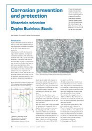
Figure 1 Overview - General <strong>Duplex</strong> Welding<br />
Guidelines<br />
www.<strong>stainless</strong>-<strong>steel</strong>-world.net S T A I N L E S S S T E E L W O R L D D E C E M B E R 2 0 0 7 53<br />
<strong>Duplex</strong><br />
ing DSS to SS, DSS is more resistant<br />
than austenitic SS to stress corrosion<br />
cracking (SCC) but not as resistant as<br />
ferritic SS; also, DSS toughness is typically<br />
superior to that of ferritic SS<br />
but not as good as austenitic SS.<br />
DSS are two phase alloys based on<br />
the iron-chromium-nickel (Fe-Cr-Ni)<br />
system. These materials typically<br />
comprise approximately equal<br />
amounts of body-centered cubic<br />
(bcc) ferrite, α-phase and face-centered<br />
cubic (fcc) austenite,<br />
γ-phase, in their microstructure. It is<br />
well documented that maximum<br />
corrosion resistance and mechanical<br />
Composition (a), wt%<br />
Common<br />
Designation C Mn S P Si Cr Ni Mo Cu W N<br />
Low-alloy grades (PREN
Element<br />
Chromium<br />
(Cr)<br />
Nickel<br />
(Ni)<br />
Molybdenum<br />
(Mo)<br />
Nitrogen<br />
(N)<br />
Weight<br />
Percentage (wt %) Elemental Role Alloying Characteristics<br />
18 to 30% Ferrite former • Increasing Cr will increase corrosion resistance.<br />
• The ferrite content increases with increasing Cr; however, too<br />
much Cr will decrease optimal phase balance.<br />
4 to 8% Austenite former • Ni promotes a change in crystal structure from ferrite to<br />
austenite.<br />
• Ni delays the formation of intermetallic phases.<br />
Less than 5% Ferrite former • Enhances pitting corrosion resistance.<br />
• Increased tendency to form detrimental intermetallic phases if<br />
Mo content is too high.<br />
Minimum of 0.14% Austenite former • N causes austenite to form from ferrite at elevated temperatures,<br />
allowing for restoration of an acceptable balance of austenite to<br />
ferrite after a rapid thermal cycle in the HAZ after <strong>welding</strong>.<br />
• Additions of N increase pitting and crevice corrosion resistance<br />
and strength.<br />
• Delays the formation of intermetallic phases.<br />
• Offsets the formation of sigma phase in high Cr, high Mo <strong>steel</strong>s.<br />
Table 2 Importance of alloying elements of DSS.<br />
properties throughout a DSS weldment<br />
are achieved when the phase<br />
balance of ferrite to austenite is<br />
50:50. However, achieving a 50:50<br />
phase balance of ferrite to austenite<br />
(α→γ) in a weldment has proven to<br />
be difficult due to many variables<br />
such as metal chemistry, <strong>welding</strong><br />
processes, and thermal history of the<br />
<strong>steel</strong>. Experience coupled with testing<br />
has shown that DSS have optimal<br />
corrosion resistance and mechanical<br />
properties when 35 to 60%<br />
ferrite content is maintained<br />
throughout the weldment. Figure 1<br />
illustrates the factors that contribute<br />
in achieving the optimal weld properties.<br />
Many fabricators lack sufficient experience<br />
controlling heat input that<br />
achieves a balanced microstructure<br />
in DSS weldments. <strong>Duplex</strong> guidelines<br />
(Figure 1) supplement API 938-<br />
C 1 and suggest parameters for <strong>welding</strong><br />
procedure specifications (WPS)<br />
that will assist welders achieve the<br />
optimum (α→γ) balance.<br />
Metallurgy<br />
Alloying Elements<br />
For DSS producers there is no difficulty<br />
in meeting standard specifications<br />
of chemical compositions.<br />
Individual <strong>steel</strong> producers have narrow<br />
target compositions within<br />
ASTM/ASME specifications to meet<br />
different criteria. DSS are sensitive<br />
to variations in composition, particularly<br />
of those elements controlling<br />
the phase balance. The relatively<br />
broad chemical limits permit large<br />
variation in properties.<br />
There are three basic categories of<br />
DSS, low-alloy, intermediate alloy,<br />
and highly alloyed, or superduplex<br />
<strong>stainless</strong> <strong>steel</strong> (SDSS) grades,<br />
grouped according to their pitting<br />
resistance equivalent number<br />
(PREN) with nitrogen and are<br />
shown in Table 1. The most widely<br />
used alloys are DSS-grade 2205+ and<br />
SDSS-grade 2507.<br />
The remarkable corrosion resistance<br />
and mechanical properties of DSS are<br />
attributed to the rich alloy content of<br />
chromium, nickel, molybdenum,<br />
and nitrogen that form austenite in a<br />
ferritic matrix. The combination of<br />
high chromium and high molybdenum<br />
is a cost-efficient way to achieve<br />
good chloride pitting and crevice<br />
corrosion resistance because of the<br />
reduced amount of nickel compared<br />
to austenitic SS. The superior attributes<br />
of DSS are credited to the interactions<br />
of alloying elements forming<br />
complex microstructures. The importance<br />
of alloying elements is explained<br />
in Table 2.<br />
Optimum (α → γ) Balance<br />
Ferrite content of DSS will indicate<br />
whether proper <strong>welding</strong> and/or heat<br />
treatment techniques result in corrosion<br />
resistance and mechanical<br />
properties that fulfil engineering requirements.<br />
The presence of ferrite<br />
in DSS imparts the superior chloride<br />
stress corrosion cracking (CSCC) resistance<br />
and high strength. An increase<br />
of ferrite content causes behaviour<br />
similar to a ferritic SS. When<br />
the amount of austenite in DSS increases,<br />
strength will decrease while<br />
corrosion resistance and susceptibility<br />
to CSCC increases. As a consequence,<br />
ferrite limits should be specified<br />
within a reasonable range and<br />
be used as a control measure.<br />
When low temperature impact<br />
properties are required, ferrite content<br />
must be carefully controlled.<br />
Figure 2 Corrosion rate and impact energy vs.<br />
percent ferrite of DSS.<br />
Figure 3: DSS micrograph (200X) 4<br />
As the ferrite content exceeds approximately<br />
60%, there will be a noticeable<br />
decrease in the ductile behaviour<br />
and pitting resistance.<br />
Sources indicate there may be a negative<br />
effect on ductile behaviour<br />
with ferrite levels below 35%, and<br />
reduced resistance to SCC due to a<br />
change in the solidification mode<br />
causing segregation and precipitation<br />
of intermetallic phases 3 .<br />
Although it is common to see 30-<br />
65% ferrite specified for base and<br />
weld metal and 30-70% ferrite HAZ,<br />
our experience shows a range between<br />
35-60% ferrite provides optimal<br />
results.<br />
Figure 2 is a theoretical diagram that<br />
illustrates how ferrite content affects<br />
DSS materials. The dotted curve<br />
represents the corrosion rate in<br />
chloride containing aqueous envi-<br />
54 S T A I N L E S S S T E E L W O R L D D E C E M B E R 2 0 0 7 www.<strong>stainless</strong>-<strong>steel</strong>-world.net
<strong>Duplex</strong> Stainless Steel<br />
°C °F<br />
Solidification range 1445 to 1385 2633 to 2525<br />
Scaling temperature in air 1000 1832<br />
Sigma phase formation 700 to 975 1292 to 1787<br />
Carbide precipitation 450 to 800 842 to 1472<br />
475C/885F embrittlement 350 to 525 662 to 977<br />
Table 3 Typical precipitation temperatures for DSS.<br />
ronments with respect to percentage<br />
of ferrite within the material. The<br />
corrosion rate is greatest below and<br />
relatively moderate above 35% ferrite.<br />
The solid curve represents impact<br />
energy at ambient temperatures<br />
with respect to the percentage<br />
of ferrite in DSS. Impact energy is at<br />
its greatest magnitude at lower ferritic<br />
levels right through to approximately<br />
60% ferrite, at which point,<br />
the impact energies begin to significantly<br />
decrease.<br />
Precipitation Mechanisms<br />
Optimum phase balance (α→γ) of a<br />
DSS is shown in Figure 3. The light<br />
globules in the dark body are unetched<br />
austenitic grains within the<br />
etched ferritic matrix respectively.<br />
DSS alloys solidify primarily as ferrite<br />
at approximately 1425°C<br />
(2597°F) and partially transform to<br />
austenite at lower temperatures by a<br />
solid state reaction 4 . If the cooling<br />
rate is rapid, very little ferrite will<br />
transform to austenite resulting in<br />
an excessive ferrite phase at room<br />
Figure 4 Pseudo-binary Fe-Cr-Ni phase at 70% Fe section<br />
illustrating areas of detrimental phase formation 5 .<br />
temperature. Consequently, the<br />
cooling rate of duplex welds must<br />
be slow enough to allow the transformation<br />
of approximately 50% of<br />
the ferrite to austenite and, at the<br />
same time, fast enough to prevent<br />
the formation of intermetallic phases<br />
and deleterious microstructures.<br />
Unwanted phases may occur during<br />
fabrication when <strong>welding</strong> differing<br />
section sizes or heavy sections with<br />
very low heat input.<br />
The high alloy content and the<br />
presence of a ferritic matrix render<br />
DSS susceptible to embrittlement<br />
and loss of mechanical properties,<br />
particularly toughness, through prolonged<br />
exposure at elevated temperatures.<br />
As cooling proceeds to lower<br />
temperatures in the range of 475-<br />
955°C (887-1750°F) for short periods<br />
of time the precipitation of carbides,<br />
nitrides and intermetallic phases, all<br />
of which can be detrimental, will<br />
occur. The most notable phases are<br />
alpha prime (α′), sigma (σ), chi (χ),<br />
and Laves (η) phases. For this reason,<br />
DSS are generally not used at<br />
temperatures above 315°C (600°F).<br />
Cooling provided by the<br />
work piece itself is the<br />
most effective method of<br />
reducing the time that<br />
the HAZ is in the temperature<br />
range formation of<br />
these intermetallic phases.<br />
The pseudo binary<br />
phase diagram, Figure 4,<br />
is a roadmap of the metallurgical<br />
behaviour of<br />
DSS, and may be used to<br />
extrapolate the temperatures<br />
at which precipitation<br />
reactions and other<br />
characteristics occur<br />
(Table 3).<br />
Heat Affected Zone<br />
(HAZ)<br />
The HAZ is the area of<br />
the base metal that has<br />
its microstructure and<br />
Figure 4: Light optical micrograph of a 50mm<br />
2205 DSS material.<br />
www.<strong>stainless</strong>-<strong>steel</strong>-world.net S T A I N L E S S S T E E L W O R L D D E C E M B E R 2 0 0 7 55<br />
<strong>Duplex</strong><br />
properties altered by inducing intensive<br />
heat into the metal. The<br />
HAZ should have corrosion resistance<br />
and impact toughness comparable<br />
to the base material minimum<br />
requirements. DSS and SDSS exhibit<br />
a narrow-HAZ, in comparison to<br />
austenitic-SS, due to the low heat<br />
input <strong>welding</strong> processes and the<br />
high thermal conductivity of the<br />
material. Typically an austenitic-SS<br />
HAZ is in the order of 500 µm in<br />
width (approximately 20 grains),<br />
whereas a DSS HAZ is often as small<br />
as 50 µm in width (2 grains). For<br />
this reason, it is extremely difficult<br />
to measure the narrow-HAZ of DSS<br />
in commercial and industrial settings.<br />
The morphology of a DSS<br />
HAZ is more important than estimating<br />
(α → γ) values. A low heat<br />
input <strong>welding</strong> process has sufficient<br />
heat to promote the transformation<br />
of discontinuous ferrite in the HAZ,<br />
and will contribute to the fine grain<br />
size responsible for the increase in<br />
toughness of the region (Figure 4).<br />
Caution is necessary when using too<br />
low a heat input associated with<br />
rapid cooling as a narrow and predominantly<br />
ferritic HAZ may be<br />
produced. Sufficient micrographs<br />
demonstrating the presence of discontinuous<br />
ferrite in the HAZ may<br />
be required to ensure a robust <strong>welding</strong><br />
process.<br />
Table 2 indicates the effects of N in<br />
DSS; furthermore, N additions to
Test Purpose Additional Details<br />
ASTM A923 Method B or C Determines if any intermetallic phases<br />
or precipitates were formed during<br />
<strong>welding</strong> process<br />
the shielding gas further support formation<br />
of austenite during cooling<br />
so that the weld and HAZ are more<br />
easily converted back to the optimal<br />
austenitic to ferritic balance. It is difficult<br />
to test the toughness in the<br />
HAZ by traditional methods since<br />
the zone is often not more than one<br />
or a few grain sizes wide 4 .<br />
DSS General Welding<br />
Guidelines<br />
Acceptable welds do not depend<br />
solely on a welder’s ability to weld<br />
DSS; it also depends on a range of<br />
variables such as base and filler<br />
material selection, pre/post-weld<br />
cleaning, joint preparation and,<br />
most importantly, choice of the most<br />
suitable <strong>welding</strong> process for a specific<br />
job. Historically, fabricators new<br />
to <strong>welding</strong> DSS spend a significant<br />
amount of time fine tuning their<br />
WPS to achieve optimal weldments.<br />
The following guidelines are intended<br />
to supplement API 938-C. The<br />
guidelines, suggest parameters for<br />
weld procedures as well as providing<br />
knowledge to create welds with excellent<br />
properties, with reasonable<br />
production, and low repair rates.<br />
Workmanship<br />
The most important factors in successfully<br />
<strong>welding</strong> DSS are quality<br />
workmanship and welder education.<br />
Rewards are significant when<br />
welders are informed and involved<br />
in the details of the weld procedure<br />
since even the <strong>best</strong> welder can create<br />
marginal welds with an excellent<br />
WPS. An informed and proactive<br />
welder can create successful, repeatable,<br />
welds when there is an understanding<br />
of the important role<br />
the variables play in achieving an<br />
optimum (α → γ) balance in DSS.<br />
Engineering<br />
The key to obtaining well balanced<br />
ferrite proportions within the basemetal,<br />
weld-metal, and HAZ is to<br />
perform Welding Procedure<br />
Specifications (WPS) and Procedure<br />
Qualification Records (PQR) that address<br />
DSS <strong>welding</strong> issues as well as<br />
all requirements and codes for weld<br />
joints and applications. According<br />
to code requirements, a WPS and<br />
PQR must meet only the minimum<br />
requirements specified in the design<br />
code. The <strong>welding</strong> of DSS demands<br />
that additional tests be conducted to<br />
Must have predetermined acceptance criteria<br />
Determine if precipitates affect corrosion resistance and mechanical<br />
properties<br />
Ferrite Readings<br />
WPS and PQR generally uses point count method<br />
(1) Point Count Method Determines % ferrite<br />
Check �–� balance for entire weldment thickness. Optimal ferrite<br />
Check content �–� between balance 35-60% for entire weldment thickness. Optimal ferrite<br />
content between 35-60%<br />
(2)Electromagnetic Measuring Determines % ferrite or FN Used during production <strong>welding</strong> to verify % ferrite in accordance with<br />
(2)Electromagnetic Method<br />
Measuring Determines % ferrite or FN Used WPS and during PQR production <strong>welding</strong> to verify % ferrite in accordance with<br />
Method<br />
WPS and PQR<br />
Sample preparation according to manufacturer’s recommendations<br />
Sample preparation according to manufacturer’s recommendations<br />
Use for WPS and PQR for comparison with production welds<br />
Use for WPS and PQR for comparison with production welds<br />
Device measurements of the weld cap and root should be within 35–<br />
Device 60% ferrite measurements content of the weld cap and root should be within 35–<br />
60% ferrite content<br />
Hardness survey Check maximum allowable hardness Depends on DSS grade and service environment<br />
Hardness survey Check maximum allowable hardness Depends on DSS grade and service environment<br />
Recommended not to exceed HV10 310<br />
Recommended not to exceed HV10 310<br />
Caution: Conversion from Vickers hardness to Rockwell for DSS is not<br />
Caution: represented Conversion by ASTMfrom E140. Vickers Refer hardness to API-938C, to Rockwell Figure for 2, for DSS hardness is not<br />
represented conversions. by ASTM E140. Refer to API-938C, Figure 2, for hardness<br />
conversions.<br />
Impact Testing Toughness measurement Typically associated with minimum design temperature and engineering<br />
Impact Testing Toughness measurement Typically recommendations associated with minimum design temperature and engineering<br />
recommendations<br />
EN specifies minimum 60J at room temperature<br />
EN specifies minimum 60J at room temperature<br />
Frequent requirements for parent and weld metal are minimum 45J<br />
Frequent average at requirements -46°C per ASTM for parent A923and Method weldB. metal The are narrow minimum HAZ45J<br />
average precludesat accurate -46°C per impact ASTM measurements A923 Methodin B. isolation. The narrow HAZ<br />
l d t i t t i i l ti<br />
Table 4: Additional details to ASME Section IX in the development of a WPS and PQR.<br />
56 S T A I N L E S S S T E E L W O R L D D E C E M B E R 2 0 0 7 www.<strong>stainless</strong>-<strong>steel</strong>-world.net<br />
<strong>Duplex</strong><br />
ensure that the weld will be suitable<br />
for the intended service and exhibit<br />
the same physical and corrosion resistant<br />
qualities as the base metal.<br />
In particular, heat inputs should be<br />
well documented in the WPS and<br />
PQR so that welders may duplicate<br />
the original during production <strong>welding</strong>.<br />
If the appropriate precautions<br />
and controls are not recognized during<br />
the WPS and PQR development<br />
stage, production welds can be<br />
plagued with problems. In addition<br />
to the requirements set forth in<br />
ASME, Section IX, or the appropriate<br />
design code for the weldment, there<br />
are a handful of additional tests and<br />
controls that should be applied to<br />
the WPS and PQR development to<br />
ensure that the welds produced are<br />
mechanically sound, corrosion resistant,<br />
and repeatable under shop<br />
or field conditions.<br />
The requirements of ASME Section<br />
IX should be addressed in the development<br />
of WPS and PQR as well as<br />
the tests listed in Table 4.<br />
Base Material Selection<br />
Base materials should be delivered<br />
in an acceptable condition since
corrosion resistance and mechanical<br />
properties of duplex alloys rely so<br />
heavily on the phase balance and<br />
absence of deleterious microstructures.<br />
Generally, DSS are produced<br />
from the mills with a good α→γ<br />
balance that is very close to 50:50;<br />
however, it is recommended that<br />
testing be conducted to verify the<br />
absence of harmful intermetallic<br />
compounds or precipitates. ASTM<br />
A923 is designed to detect the presence<br />
of intermetallic phases in the<br />
mill product of DSS to the extent<br />
that toughness or corrosion resistance<br />
is affected significantly 6 . It<br />
should be noted that the test methods<br />
will not necessarily detect losses<br />
of toughness or corrosion resistance<br />
attributable to other causes 6 . Good<br />
practice is to verify %ferrite of the<br />
base metal prior to <strong>welding</strong>.<br />
Dissimilar metal welds (DMW) between<br />
DSS and other materials must<br />
be evaluated case by case. Generally,<br />
it is possible to weld all grades of<br />
DSS to DSS, carbon <strong>steel</strong> (CS), alloy<br />
<strong>steel</strong>, and austenitic SS 1 . In some<br />
cases it is necessary to use buttering<br />
techniques to avoid PWHT of the<br />
final weld.<br />
Weld Preparation<br />
Proper cleaning prior to <strong>welding</strong> is a<br />
foundation for successful DSS welds.<br />
Prior to any <strong>welding</strong>, all weld bevels<br />
should be examined using liquid<br />
penetrant testing for edge defects<br />
and laminations for all thicknesses<br />
greater than 6 mm (0.24 in), and<br />
visually inspected for nicks, dents,<br />
general damage or other surface<br />
irregularities. It is also important to<br />
clean the surrounding weld area,<br />
usually 2 inches back from the bevel,<br />
with grinding pads, then wiped<br />
with an approved solvent. Grinding<br />
pads, soft packs, wire brushes and<br />
others tools used in austenitic SS<br />
fabrication are acceptable for use on<br />
DSS. The base metal should also be<br />
cleaned of rust blooms and embedded<br />
iron.<br />
Additional precautions for DSS<br />
should always be in place to minimize<br />
iron contamination. Some DSS<br />
are susceptible to iron contamination<br />
by free iron, whether it be impregnated<br />
or on the surface. The<br />
contamination mechanism is a galvanic<br />
reaction when an electrolyte<br />
is present. Fabricators should have<br />
an inspection procedure in place to<br />
prevent iron contamination in accordance<br />
with ASTM A380 7 .<br />
Measures to protect cleaned surfaces<br />
should be taken as soon as the final<br />
cleaning is completed and should be<br />
maintained during all subsequent<br />
fabrication, shipping, inspection,<br />
storage, and installation. Finished,<br />
cleaned materials should not be<br />
stored on the ground or floor, and<br />
should not be permitted to come in<br />
contact with asphalt, galvanized<br />
carbon <strong>steel</strong>, mercury, zinc, lead,<br />
brass, low melting point metals, or<br />
alloys that have been in contact<br />
with such materials 7 . Store DSS material<br />
and equipment on wood<br />
skids, pallets or metal surfaces, that<br />
are protected and prevent direct<br />
contact with the DSS surface. Keep<br />
openings of pipes, tubes, valves,<br />
tanks, pumps, and pressure vessels,<br />
etc., capped or sealed at all times except<br />
when in use.<br />
Joint Preparation<br />
Joint preparations for DSS are typically<br />
common to austenitic SS; however,<br />
deviations exceeding 20% of<br />
the PQR parameters may have significant<br />
detrimental effects on weld<br />
consistency. Experience shows that<br />
DSS can be cut using the plasma-arc<br />
process, a machine cutter, or grinding<br />
disc dedicated solely for the use<br />
on DSS. If plasma-arc cutting is<br />
used, the inside surface must be<br />
thoroughly cleaned of all spatter.<br />
Sufficient metal should be removed<br />
in the bevelling process to eliminate<br />
any HAZ that occurred as a result of<br />
the plasma-arc cutting. Carbon-arc<br />
should not be used for cutting or<br />
back gouging.<br />
When DSS welds are to be completed<br />
from one side, a slightly wider<br />
gap and a more open angle is preferable<br />
since duplex filler metals do<br />
not penetrate as deeply as austenitic<br />
SS filler metals. To achieve a maximum<br />
of 50% dilution in the root<br />
pass, a wider gap is needed to allow<br />
additional filler to be deposited.<br />
The final surface preparation and<br />
configuration should be obtained by<br />
machining or grinding. During machining<br />
operations, only a cutting<br />
fluid compatible with SS should be<br />
used. Any small burrs, nicks, or oth-<br />
er irregularities on the weld bevel<br />
should be repaired, if possible, by<br />
light grinding. Follow necessary<br />
cleaning procedures.<br />
Welding Process Selection<br />
Process selection is usually dictated<br />
more by the availability of consumables,<br />
economics, and logistic considerations<br />
than by end desired properties.<br />
As well, it is commonly mistaken<br />
that DSS can be welded similarly<br />
to austenitic SS. For DSS, the narrow<br />
<strong>welding</strong> parameters and specific filler<br />
metals defined in the PQR must be<br />
closely monitored to maintain a balanced<br />
microstructure. If the balance<br />
is significantly altered and the two<br />
phases are no longer in similar proportions,<br />
then loss of material properties<br />
can be significant. Where exceptional<br />
low-temperature toughness<br />
is required, gas-shielded processes<br />
may be specified to produce higher<br />
weld metal toughness properties<br />
than flux-shielded processes 2 .<br />
Gas tungsten arc <strong>welding</strong> (GTAW),<br />
shielded metal arc <strong>welding</strong> (SMAW),<br />
submerged arc <strong>welding</strong> (SAW), flux<br />
cored arc <strong>welding</strong> (FCAW), gas metal<br />
arc <strong>welding</strong> (GMAW) and plasma arc<br />
<strong>welding</strong> (PAW) are commonly used<br />
with success for most DSS grades.<br />
Although all of the common arc<br />
<strong>welding</strong> processes are suitable for<br />
<strong>welding</strong> DSS, generally a <strong>welding</strong><br />
process is selected based on suitability<br />
for the <strong>welding</strong> environment<br />
(whether it is field or shop <strong>welding</strong>),<br />
size, type, orientation of joints, and<br />
the required balance between speed<br />
and quality. Once the process has<br />
been selected, it can be optimized<br />
for the specific grade of DSS being<br />
joined.<br />
Autogenous <strong>welding</strong>, such as electron-beam<br />
<strong>welding</strong> and laser-beam<br />
<strong>welding</strong>, is not very suitable for the<br />
<strong>welding</strong> of DSS since this process<br />
creates welds with very high ferrite<br />
content. In these cases, a solutionanneal<br />
PWHT can restore an acceptable<br />
weld and HAZ phase balance<br />
and remove undesirable precipitates<br />
provided ideal cooling rates are followed.<br />
Shielding and Backing Gas<br />
Pure argon (Ar) shielding and backing<br />
gases can create weldments with<br />
sufficient corrosion resistance.<br />
58 S T A I N L E S S S T E E L W O R L D D E C E M B E R 2 0 0 7 www.<strong>stainless</strong>-<strong>steel</strong>-world.net
Table 5 Shielding gas general recommendations.<br />
Welding Process Gas Types<br />
GTAW 99.996%Ar, Ar+2%N2, Ar+5%N2<br />
GMAW Ar+1%O2, Ar+30%He+1%O2, Ar+2%CO2, Ar+15%He+2%CO2<br />
FCAW Ar+1% O2, Ar+20%CO2, Ar+2%CO2<br />
PAW 99.996%Ar<br />
Table 6 DSS and SDSS consumable specifications.<br />
Alloy Process AWS Specification BS EN Specification<br />
DSS GTAW ER 2209 W 22 9 3 N L<br />
GMAW ER 2209 G 22 9 3 N L<br />
SMAW E 2209-15/16/17 E 22 9 3 N L B/R<br />
FCAW E 2209 t0-1/4, E 2209 t1-1/4 T 22 9 3 N L R/P<br />
SAW ER2209+flux S 22 9 3 N L R/P<br />
SDSS GTAW - W 25 9 4 N L<br />
GMAW - G 25 9 4 N L<br />
SMAW - E 25 9 4 N L B/R<br />
FCAW - -<br />
SAW - S 25 9 4 N L + flux<br />
However, N loss is not uncommon<br />
to a depth of 0.5 mm from the surface<br />
of the weld. To correct the<br />
phase balance and improve corrosion<br />
resistance of the weld, it is beneficial<br />
to have additions of 1-2% N<br />
in the Ar shielding and 90% N and<br />
10% hydrogen (H) in the backing<br />
gas. Nitrogen contents above 2% in<br />
the shielding gas can cause degradation<br />
of the tungsten electrode for<br />
GTAW processes. The addition of H<br />
to the shielding gas is not recommended<br />
as it may cause H absorption<br />
in the weld.<br />
Back purging should be maintained<br />
on the joint until at least 6 mm of<br />
weld metal thickness has been deposited.<br />
The oxygen content of the<br />
back purged volume should not exceed<br />
0.25% (2500 ppm) 1 .<br />
Since DSS have relatively high<br />
chromium contents and relatively<br />
low thermal expansion, an oxide<br />
scale appearing as an oxide tint is<br />
produced during <strong>welding</strong> that is<br />
typically thin and difficult to remove.<br />
The appearance and amount<br />
of heat-tint produced during <strong>welding</strong><br />
can be minimized with low levels<br />
of oxygen (below 0.25%) in the<br />
shielding and backing gases, with<br />
minimal moisture in the backing<br />
gas, and with limiting contaminants<br />
on the surface prior to <strong>welding</strong>.<br />
Hydrogen in the Ar backing gas can<br />
adversely affect the appearance of<br />
heat tint, and the base metal’s surface<br />
finish. Shielding gases suitable<br />
for the various gas shielded processes<br />
are listed in Table 5.<br />
Filler Metal Selection<br />
Welding consumables for DSS are<br />
similar in composition to that of the<br />
base material, but the consumables<br />
do require nitrogen and higher levels<br />
of nickel to ensure an appropriate<br />
phase balance in the deposited weld<br />
metal. A nitrogen addition in filler<br />
metals, 0.14-0.20% N, helps to prevent<br />
the formation of σ phases.<br />
Increased addition of Ni promotes a<br />
change in crystal structure from ferrite<br />
to austenite and also delays the<br />
formations of intermetallic phases. A<br />
weld metal microstructure from a<br />
filler composition exactly matching<br />
that of the base metal would yield<br />
high ferrite content, off balancing<br />
the optimal α→γrequired. It is important<br />
that the Cr-content of the<br />
deposited filler metal selected provides<br />
a close match of the base metal.<br />
DSS and SDSS may be welded with a<br />
DSS filler metal that is alloyed with<br />
higher amounts of Ni or, alternatively,<br />
they could be welded with a fully<br />
austenitized Ni-alloy filler metal.<br />
Welding DSS-2205 with ER 2209<br />
filler metal is an effective method of<br />
achieving optimal α→γphase balance.<br />
The ER 2209 filler metal has<br />
equal quantities of Cr-content as<br />
well as 7 to 9% nickel compared to<br />
the 5.5% nickel of the base metal.<br />
Table 6 lists consumable specifications<br />
for DSS and SDSS according<br />
American Welding Society (AWS)<br />
and British Standard (BS).<br />
Welding SDSS-2507 using ER 2209<br />
filler metal is not advised due to under-matching<br />
chemistry. Some fabricators<br />
use AWS ER 2553 for <strong>welding</strong><br />
SDSS-2507; however this practice is<br />
not recommended due to undermatching<br />
Ni-content and unaccept-<br />
www.<strong>stainless</strong>-<strong>steel</strong>-world.net S T A I N L E S S S T E E L W O R L D D E C E M B E R 2 0 0 7 59<br />
<strong>Duplex</strong><br />
ably high addition of copper (Cu).<br />
Increased Cr-content and low<br />
Ni-content of the filler metal will<br />
produce welds and HAZ with excess<br />
ferrite upon <strong>welding</strong>. The increased<br />
Cu additions will produce detrimental<br />
Cu precipitates (ε-phase) as Cu has<br />
a low solubility in ferrite (
ing as it may negatively affect cooling<br />
rates required to achieve optimal<br />
phase balance. There may be instances,<br />
for example thick-wall to<br />
thin-wall, where weldments may require<br />
a small degree of preheating to<br />
prevent too rapid a cooling rate.<br />
These instances should be reviewed<br />
by a <strong>welding</strong> engineer on a case by<br />
case basis.<br />
The maximum recommended interpass<br />
temperature should not exceed<br />
200°C (392°F) for DSS alloys and<br />
150°C (302°F) for SDSS alloys<br />
throughout <strong>welding</strong> operations 2 .<br />
Excessive interpass temperatures can<br />
cause embrittlement and low impact<br />
values in the root region. Take temperature<br />
readings on the base metal<br />
surface, directly adjacent to the weld<br />
groove 1 . Note that wall thicknesses<br />
greater than 25 mm will have higher<br />
temperatures deep in the weld than<br />
the temperature measured on the<br />
surface. In these situations, harmful<br />
phases could form over prolonged<br />
time.<br />
Heat Input<br />
Heat input significantly affects the<br />
cooling rate that results in the final<br />
microstructure. Too low a heat input<br />
will often result in a weld that is predominantly<br />
ferritic and will not have<br />
the same characteristics as the base<br />
metal. Often a moderately low preheat<br />
(below 75°C (167°F)) combined<br />
with low heat input can achieve optimum<br />
phase balance without the formation<br />
of excessive ferrite.<br />
Conversely, high a heat input results<br />
in slow cooling rates that increase<br />
the risk of the formation of intermetallic<br />
compounds or precipitates<br />
in the weld and HAZ. Choose a heat<br />
input with an appropriate intermediate<br />
cooling rate that favors austenite<br />
re-formation at high temperatures<br />
and retards sigma formation at lower<br />
temperature 1 . For DSS, a relatively<br />
low heat input, in the range of 0.5-<br />
2.5 kJ/mm and for SDSS, 0.2-1.5<br />
KJ/mm has been successfully used.<br />
Post-Weld Heat Treatment<br />
(PWHT) and Cleaning<br />
PWHT of DSS is generally not required<br />
but may be necessary when<br />
detrimental amounts of intermetallic<br />
phases have formed. Typically, a<br />
full solution anneal followed by a<br />
water quench should be considered.<br />
When correction heat treatments<br />
are not possible, cut out and replacement<br />
should be considered.<br />
Post weld cleaning is required to<br />
maintain the corrosion resistance.<br />
Removal of any heat tint helps to<br />
achieve maximum heat resistance.<br />
Grinding to clean bright metal is effective.<br />
Blasting might be effective,<br />
but depending on the scale and the<br />
blasting medium it may not be as<br />
effective as grinding.<br />
Testing for Optimum<br />
Properties<br />
At present, experimental methods<br />
are not available that give absolute<br />
measurements of the ferrite content<br />
in weld metal, either destructively<br />
or non-destructively. This situation<br />
has led to the development and use,<br />
internationally, of the concept of a<br />
“ferrite number” (FN). The FN is a<br />
description of the ferrite content of<br />
a weld metal determined using a<br />
standardized procedure. FN is approximately<br />
equivalent to the<br />
weight percentage ferrite content,<br />
particularly at low FN values.<br />
A number of methods exist to measure<br />
the ferrite of a given sample although,<br />
historically, there is a great<br />
deal of confusion over which<br />
method to apply and how to interpret<br />
the results. The most common<br />
methods to measure ferrite content<br />
of DSS are point count method<br />
(PCM) and an electromagnetic<br />
measuring device (EMD), both governed<br />
by ASTM E562. The PCM, a<br />
more time consuming but more<br />
accurate method, is <strong>best</strong> to verify<br />
the consistency of balanced α→γ<br />
during WPS and PQR development<br />
because it is a destructive test.<br />
The EMD is a preferred method for<br />
verifying the austenite to ferrite<br />
ratio of production welds. The ferrite<br />
content determined by these<br />
methods is arbitrary and is not necessarily<br />
the true or absolute ferrite<br />
content throughout the weldment<br />
thickness. The relative percent accuracy<br />
is based on unbiased statistical<br />
estimations described in ASTM E562.<br />
Point Count Method (PCM)<br />
The PCM is a systematic, manual<br />
counting procedure for statistically<br />
estimating the volume fraction of an<br />
www.<strong>stainless</strong>-<strong>steel</strong>-world.net S T A I N L E S S S T E E L W O R L D D E C E M B E R 2 0 0 7 61<br />
<strong>Duplex</strong><br />
identifiable constituent or phase.<br />
This method requires a mounted and<br />
polished planar cross section of the<br />
weld specimen, a method that cannot<br />
be applied to production welds,<br />
but can be applied to WPS and PQR.<br />
The PCM verifies α→γbalance in<br />
the PQR test coupons to provide assurance<br />
that the WPS will yield optimum<br />
phase balance during production<br />
<strong>welding</strong>. Tests are recommended<br />
for the following locations:<br />
• In the parent metal, one measurement<br />
on each side of the weld at<br />
mid thickness (total 2).<br />
• In the HAZ on each side of the<br />
weld, in the region of the root<br />
pass (total 2). Sufficient micrographs<br />
may be required to ensure<br />
discontinuous ferrite along the<br />
narrow HAZ.<br />
• In the weld metal, 3 measurements<br />
near to the vertical center<br />
line of the weld, one in the cap,<br />
one in the root, and one at mid<br />
thickness (total 3).<br />
Electromagnetic Measuring<br />
Device (EMD)<br />
An EMD provides fast and easy readings<br />
without any significant preparation<br />
or the requirement to section<br />
welds and verifies that ferrite values<br />
do not deviate significantly from<br />
values in the WPS and PQR. The<br />
Fischer Feritscope ® MP30E is an example<br />
of an EMD that measures<br />
both ferrite numbers (FN) and percent<br />
ferrite according to the magnetic<br />
induction method. This device<br />
can measure from 0.1 to 110 FN and<br />
0.1 to 80% ferrite 8 . Production ferrite<br />
tests should be performed at intervals<br />
of 3 tests every 5 feet of<br />
weld; one in each of the base metal<br />
and weld metal. All single point<br />
measurements from this method<br />
should be within the specified<br />
range. Surface preparation should<br />
follow the manufacturers recommendations.<br />
The ferrite content of<br />
the narrow HAZ cannot be accurately<br />
measured by this method.<br />
Conclusions<br />
Good corrosion resistance and mechanical<br />
properties of DSS are the result<br />
of well crafted WPS/PQR that<br />
define heat inputs and cooling rates<br />
to achieve weldments with optimum<br />
ferrite to austenite balance. The
presence of ferrite in DSS imparts<br />
the superior CSCC resistance and<br />
high strength. On the other hand,<br />
austenite in DSS provides the high<br />
aqueous corrosion resistance and<br />
low temperature impact toughness.<br />
The recommended phase balance of<br />
DSS and SDSS should contain 40-<br />
60% ferrite in the base metal and<br />
35-60% ferrite in the weld metal.<br />
Special consideration must be given<br />
to the narrow-HAZ. It is essential to<br />
have a discontinuous fine grain microstructure<br />
of ferrite and austenite<br />
in the narrow region.<br />
DSS shows rather complex precipitation<br />
behaviour due to the high<br />
amount of alloying elements. The<br />
formation of carbides, nitrides and<br />
intermetallic phases, which can be<br />
detrimental, will begin to form in<br />
short periods of time as cooling proceeds<br />
to lower temperatures in the<br />
range of 475-955°C (887-1750°F).<br />
For this reason DSS should not be<br />
used at temperatures above 300°C<br />
(570°F).<br />
Optimum DSS welds depend on<br />
multiple factors such as engineering<br />
design, material selection, pre/postweld<br />
cleaning, joint preparation and<br />
most importantly, choice of a suitable<br />
<strong>welding</strong> process. Guidelines<br />
supplement API 938C and provides<br />
recommendations for WPS and PQR<br />
development to achieve an optimum<br />
ferrite to austenite balance<br />
during <strong>welding</strong>.<br />
More than<br />
20 years of Competence<br />
Our<br />
grades:<br />
References<br />
1. API Technical Report 938-C. 2005. Use of <strong>Duplex</strong> Stainless Steels in the Oil Refining Industry:<br />
American Petroleum Institute: First Edition. Washington, D.C.<br />
2. Davis, J.R. Corrosion of Weldments: ASM International ® (2006): Materials Park, OH 44073-002.<br />
3. Gooch, T.G., Leonard, A.J., and Gunn, R.N. 2000. Hydrogen cracking of ferritic-austenitic <strong>stainless</strong><br />
<strong>steel</strong> weld metal (DA2_058): Stainless Steel World: Page 354-357.<br />
4. Sieurin, H., and Sandström, R. Austenite Reformation in the heat-affected zone of duplex <strong>stainless</strong><br />
<strong>steel</strong> 2205: Material Science Engineering A 418 (2006) 250-256.<br />
5. Pohl, M., Storz, O., Glogowski, T. Effect of intermetallic precipitations on the properties of duplex<br />
<strong>stainless</strong> <strong>steel</strong>. Material Science Engineering 58 (2007) 65-71.<br />
6. ASTM © Standards A 923, Standard Test Methods for Detecting Detrimental Intermetallic Phase in<br />
Wrought <strong>Duplex</strong> Austenitic/Ferritic Stainless Steels.<br />
7. ASTM © Standards A 380, Standard Practice for Cleaning, Descaling, and Passivation of Stainless<br />
Steel Parts, Equipment, and Systems.<br />
8. BS 6787:1987, ISO 8249:1985. Determination of ferrite number in austenitic weld metal deposited<br />
by covered Cr-Ni <strong>steel</strong> electrodes: British Standard.<br />
About the authors<br />
Barry Messer is<br />
Technical Director and<br />
Senior Fellow for<br />
Materials and Welding<br />
Engineering with Fluor<br />
Canada Ltd. and a director<br />
with the<br />
Canadian Welding Bureau. Barry has<br />
over 30 years experience in metallurgy,<br />
<strong>welding</strong>, and NDE development and<br />
material selection. He is regularly involved<br />
in the analysis and mitigation of<br />
fabrication and in-service failures for<br />
the chemical, petroleum, power, and<br />
mining industries.<br />
barry.messer@fluor.com<br />
Vasile Oprea is a<br />
Senior Metallurgical<br />
and Welding Engineer<br />
with Fluor Canada Ltd.<br />
He has over 25 years<br />
experience in material<br />
selection, <strong>welding</strong>, heat<br />
treatment, NDE, and failure analysis.<br />
Andrew Wright is a<br />
metallurgical Engineer<br />
with Fluor Canada Ltd.<br />
He provides <strong>welding</strong><br />
and metallurgical support<br />
for piping and<br />
equipment fabrication.<br />
Andrew is currently involved in high alloy<br />
<strong>welding</strong> issues on international<br />
petrochemical projects.<br />
www.<strong>stainless</strong>-<strong>steel</strong>-world.net S T A I N L E S S S T E E L W O R L D D E C E M B E R 2 0 0 7 63<br />
<strong>Duplex</strong><br />
Heat-Resistant Stainless Steel Tubes<br />
We offer one of the widest ranges in Europe<br />
1.4713<br />
TP 409 1.4720<br />
TP 405 1.4724<br />
TP 430 1.4742<br />
TP 446 1.4749<br />
TP 446 1.4762<br />
TP 327 1.4821<br />
TP 309 1.4828<br />
TP 314 1.4841<br />
TP 310s 1.4845<br />
TP 330 1.4864<br />
Alloy 800 1.4876<br />
Schenk Stahl GmbH<br />
P.O. Box 27 03 38, D-40526 Düsseldorf, Germany<br />
Tel: +49 2131 230-37, Fax: +49 2131 230-35<br />
info@schenk-stahl.de, www.schenk-stahl.de<br />
TP 32/27 1.4877<br />
TP 321 H 1.4878<br />
Alloy 600 2.4816<br />
Alloy 601 2.4851<br />
Alloy 625 2.4856<br />
Alloy 825 2.4858<br />
·SCHENK·<br />
H E A T-RESISTANT<br />
T U B E S