OSA-Link Cable Clone - Arena
OSA-Link Cable Clone - Arena
OSA-Link Cable Clone - Arena

You also want an ePaper? Increase the reach of your titles
YUMPU automatically turns print PDFs into web optimized ePapers that Google loves.
<strong>OSA</strong>-<strong>Link</strong> <strong>Cable</strong> <strong>Clone</strong><br />
The Scisys Leonardo and Saitek Galileo and Renaissance chess computers could be connected to a<br />
PC via an <strong>OSA</strong>-<strong>Link</strong> cable. Such a cable is needed to run the <strong>OSA</strong>-4-<strong>Arena</strong> software and other<br />
tools. Unfortunately that cable is no longer available.<br />
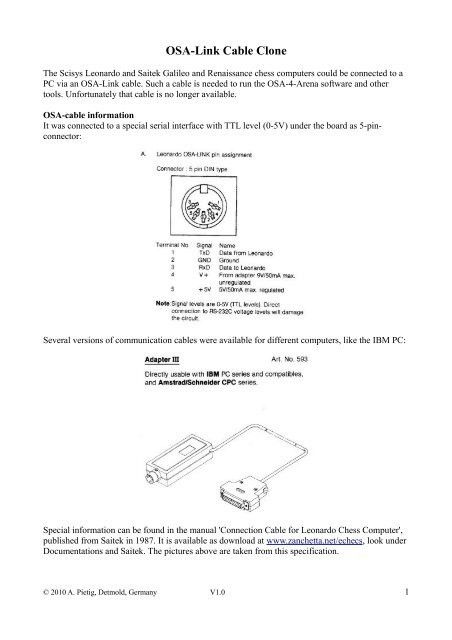
<strong>OSA</strong>-cable information<br />
It was connected to a special serial interface with TTL level (0-5V) under the board as 5-pinconnector:<br />
Several versions of communication cables were available for different computers, like the IBM PC:<br />
Special information can be found in the manual 'Connection <strong>Cable</strong> for Leonardo Chess Computer',<br />
published from Saitek in 1987. It is available as download at www.zanchetta.net/echecs, look under<br />
Documentations and Saitek. The pictures above are taken from this specification.<br />
© 2010 A. Pietig, Detmold, Germany V1.0 1
The PC side of the cable has a RS232 (±12V) serial interface. A small box between the interfaces<br />
contains a TTL-RS232 converter.<br />
On the PC side (right) only GNG, RxD and TxD are connected. The <strong>OSA</strong> interface (left) has GND,<br />
RxD, TxD, 5V (regulated) and 9V (unregulated). Both voltages are needed by the TTL-RS232<br />
converter MC1488P. The IC on the left (yellow circle) is a regulator for the 9V from the <strong>OSA</strong><br />
interface. The next picture shows the original circuit diagram.<br />
© 2010 A. Pietig, Detmold, Germany V1.0 2
Possible replacements<br />
Is is relative easy to re-assemble an <strong>OSA</strong>-cable. You will need a modern IC for the TTL-RS232<br />
conversion and two cables, one with a 5-pin-DIN male jack and the other with a 9-pin female<br />
RS232 socket.<br />
As IC you can take the well known MAX 232 or an ADM232L. Both ICs need only 5V to operate,<br />
so the 9V from the board is not needed and will make the work easier.<br />
The next pictures show the principle circuits for both ICs.<br />
For the ADM232L you will need 5 condensers with 1 µF each, that's all. The IC has two<br />
communication lines (T1/R1 and T2/R2), for <strong>OSA</strong> only one will be used.<br />
© 2010 A. Pietig, Detmold, Germany V1.0 3
The MAX232 is very similar.<br />
You can choose any of these ICs and assemble your own circuit, but it will be much easier to buy a<br />
ready-to-go assembly kit. A fellow at www.schachcomputer.info found a very nice kit at<br />
www.pollin.de, a german electronic distributor. It is still possible to order the kit from foreign<br />
countries.<br />
© 2010 A. Pietig, Detmold, Germany V1.0 4
TTL-RS232 adapter from Pollin<br />
The german company Pollin offers a complete assembly kit for the TT-RS232 conversion. It is<br />
small, easy to build and cheap.<br />
You can order via internet at www.pollin.de:<br />
Order-No. Article Price EUR<br />
810036 Bausatz RS232-TTL-Wandler 3,95<br />
720738 Sub-D-Verlängerungskabel, 9-pol., 1,8m 1,25<br />
560172 Audiokabel, 2x DIN-Stecker 5-pol., 1,5m 1,95<br />
The Sub-D cable is for the connection from the adapter to the PCs serial interface and optional, if<br />
you don't have one. If your PC or Laptop does not have a serial interface, you can use an USB-to-<br />
RS232-adapter (not available at Pollin).<br />
The 5-pol.-DIN cable is for the connection to your chess computer. One of the plugs will be cut off<br />
and the single cables will be plugged into the clamp of the Pollin adapter.<br />
© 2010 A. Pietig, Detmold, Germany V1.0 5
Buildup<br />
You will get the following parts from pollin for the TTL-RS232 adapter:<br />
The connectors for the TTL-cable and the RS232 jack are self-descriptive. At the bottom of the<br />
picture you see a condenser of 100 nF (C5), the fitting direction doesn't matter.<br />
The IC (MAX232) should be fit with the notch at one end into the corresponding place on the<br />
circuit board:<br />
© 2010 A. Pietig, Detmold, Germany V1.0 6
The condensers on the left with 10 µF have a plus/minus orientation. It is important to fit them in<br />
the right orientation to the circuit. Plus is marked on the board with a + and minus with a bold-white<br />
line (see C1 to C4). The condensers are marked with a coloured line and the number 0 in it for the<br />
minus pole.<br />
The next picture shows the printout of the circuit board with the position of all parts.<br />
© 2010 A. Pietig, Detmold, Germany V1.0 7
© 2010 A. Pietig, Detmold, Germany V1.0 8
After assembling the circuit and careful soldering of all contacts the item should look as follows:<br />
The PC side is now still ready and you can connect a 9-pol-Sub-D cable to the left. For the chess<br />
board side only the above four connections are needed (5V, GNG/Masse, TxD, RxD).<br />
Take the 5-pol-DIN cable, cut off one plug and strip the wires. Then check which wire (different<br />
colour) is connected with what pin at the DIN-plug. Check that the plug is in the correct orientation<br />
with the <strong>OSA</strong>-plug layout.<br />
© 2010 A. Pietig, Detmold, Germany V1.0 9
Use a measurement device to find out the cable connection and write it down.<br />
The 5-pol-DIN cable from Pollin has the following connections:<br />
PIN-No. Description Colour<br />
1 TxD blue<br />
2 GND yellow<br />
3 RxD red<br />
5 5V white<br />
The wire to pin 4 is not used and can be cut off. The colours may vary from manufacturer to<br />
manufacturer, even if you buy it from the same vendor. So please check the cable connections<br />
carefully!<br />
To fit the wired into the plugs of the circuit board it is a good idea to fold the ends. This will give a<br />
more stable connection in the screwed plugs. Do not tin-plate the wires with solder, just use the<br />
copper wires as they are.<br />
© 2010 A. Pietig, Detmold, Germany V1.0 10
Now you can fit the wires into the plugs of the circuit board.<br />
Fit 5V (white) into the right plug and GND (yellow) in the second plug. RxD (red) shall be fit into<br />
the TxD-plug and TxD (blue) shall be fit into the 4 th plug (RxD) of the circuit board.<br />
That's all, now you have your own <strong>OSA</strong>-<strong>Link</strong> cable and can use all of the available software for<br />
your chess computer. Have fun!<br />
Note:<br />
All informations are provides 'as is' and there are no guarantees for the hardware. I'm not<br />
responsible for any damage that may occur, using such a cable is at your own risk.<br />
© 2010 A. Pietig, Detmold, Germany V1.0 11