A novel ultra sensitive method for voltage noise ... - Felice Crupi
A novel ultra sensitive method for voltage noise ... - Felice Crupi
A novel ultra sensitive method for voltage noise ... - Felice Crupi

You also want an ePaper? Increase the reach of your titles
YUMPU automatically turns print PDFs into web optimized ePapers that Google loves.
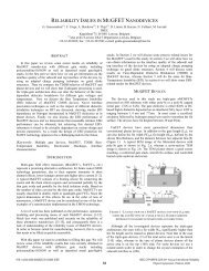
where S DUT is the power spectral density (PSD) of the<br />
equivalent <strong>noise</strong> source of the DUT, and S Ci is the PSD due to<br />
the EICN of the amplifier i.<br />
DUT<br />
1<br />
2<br />
3<br />
4<br />
Spectrum<br />
Analyzer<br />
Figure 2 – Schematics of the proposed instrument <strong>for</strong> <strong>voltage</strong> <strong>noise</strong><br />
measurements. The DUT can be connected either to one of the two<br />
couples of amplifiers or to both couples. The spectrum analyzer<br />
per<strong>for</strong>ms the cross-correlation between the outputs of any two<br />
amplifiers.<br />
residual contribution of the (uncorrelated) EIVN of the<br />
amplifiers negligible with respect to the DUT <strong>noise</strong> to be<br />
measured.<br />
While the above requirements are common to almost all<br />
the high sensitivity <strong>method</strong>s mentioned above, the new<br />
<strong>method</strong> has the very important advantages of not requiring<br />
any preliminary characterization of the DUT impedance and<br />
of the EICN of the amplifiers and of not relying on the<br />
hypothesis of the EICN having a negligible effect. In fact, by<br />
using the technique we propose, it is possible to accurately<br />
estimate the <strong>voltage</strong> <strong>noise</strong> produced by the DUT even in the<br />
case in which its impedance is so high that the contribution of<br />
the EICN of the amplifiers becomes predominant.<br />
Finally we would like to note that by using the very same<br />
principle we have developed above, one can obtain similar<br />
results by using just three amplifiers instead of four, at the<br />
cost, however, of a further measurement step.<br />
III.<br />
EXPERIMENTAL VALIDATION<br />
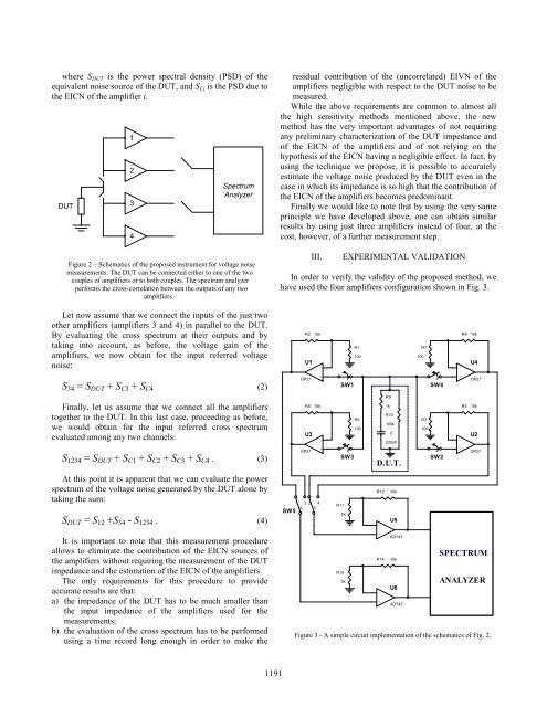
In order to verify the validity of the proposed <strong>method</strong>, we<br />
have used the four amplifiers configuration shown in Fig. 3.<br />
Let now assume that we connect the inputs of the just two<br />
other amplifiers (amplifiers 3 and 4) in parallel to the DUT.<br />
By evaluating the cross spectrum at their outputs and by<br />
taking into account, as be<strong>for</strong>e, the <strong>voltage</strong> gain of the<br />
amplifiers, we now obtain <strong>for</strong> the input referred <strong>voltage</strong><br />
<strong>noise</strong>:<br />
R2 10k<br />
U1<br />
-<br />
R1<br />
100<br />
R7<br />
100<br />
R8 10k<br />
-<br />
U4<br />
S 34 = S DUT + S C3 + S C4 (2)<br />
Finally, let us assume that we connect all the amplifiers<br />
together to the DUT. In this last case, proceeding as be<strong>for</strong>e,<br />
we would obtain <strong>for</strong> the input referred cross spectrum<br />
evaluated among any two channels:<br />
OP27<br />
R9<br />
R6 10k 1k<br />
R4 10k<br />
U3<br />
-<br />
+<br />
+<br />
SW1<br />
R10<br />
R5<br />
R3<br />
100k<br />
100<br />
100<br />
C<br />
220nF<br />
SW4<br />
-<br />
OP27<br />
U2<br />
S 1234 = S DUT + S C1 + S C2 + S C3 + S C4 . (3)<br />
OP27<br />
+<br />
SW3<br />
D.U.T.<br />
SW2<br />
+<br />
OP27<br />
At this point it is apparent that we can evaluate the power<br />
spectrum of the <strong>voltage</strong> <strong>noise</strong> generated by the DUT alone by<br />
taking the sum:<br />
S DUT = S 12 +S 34 - S 1234 . (4)<br />
SW5 6<br />
1 3 2 4<br />
5<br />
R11<br />
1K<br />
R12<br />
-<br />
10k<br />
U5<br />
It is important to note that this measurement procedure<br />
allows to eliminate the contribution of the EICN sources of<br />
the amplifiers without requiring the measurement of the DUT<br />
impedance and the estimation of the EICN of the amplifiers.<br />
The only requirements <strong>for</strong> this procedure to provide<br />
accurate results are that:<br />
a) the impedance of the DUT has to be much smaller than<br />
the input impedance of the amplifiers used <strong>for</strong> the<br />
measurements;<br />
b) the evaluation of the cross spectrum has to be per<strong>for</strong>med<br />
using a time record long enough in order to make the<br />
R14<br />
R13<br />
1K<br />
+<br />
+<br />
-<br />
AD743<br />
10k<br />
U6<br />
AD743<br />
SPECTRUM<br />
ANALYZER<br />
Figure 3 - A simple circuit implementation of the schematics of Fig. 2.<br />
1191