Voir la documentation - AWF Woodward France
Voir la documentation - AWF Woodward France
Voir la documentation - AWF Woodward France

Create successful ePaper yourself
Turn your PDF publications into a flip-book with our unique Google optimized e-Paper software.
Product Specification<br />
82043B<br />
4024 All Electric<br />
Governor System<br />
• No Mechanical<br />
Drive or Hydraulic<br />
Supply is Required<br />
for Governor<br />
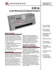
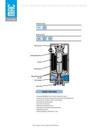
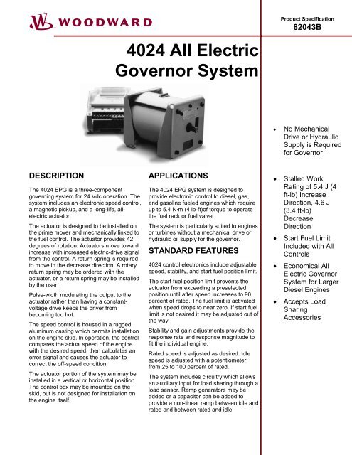
DESCRIPTION<br />
The 4024 EPG is a three-component<br />
governing system for 24 Vdc operation. The<br />
system includes an electronic speed control,<br />
a magnetic pickup, and a long-life, allelectric<br />
actuator.<br />
The actuator is designed to be installed on<br />
the prime mover and mechanically linked to<br />
the fuel control. The actuator provides 42<br />
degrees of rotation. Actuators move toward<br />
increase with increased electric-drive signal<br />
from the control. A return spring is required<br />
to move in the decrease direction. A rotary<br />
return spring may be ordered with the<br />
actuator, or a return spring may be installed<br />
by the user.<br />
Pulse-width modu<strong>la</strong>ting the output to the<br />
actuator rather than having a constantvoltage<br />
drive keeps the driver from<br />
becoming too hot.<br />
The speed control is housed in a rugged<br />
aluminum casting which permits instal<strong>la</strong>tion<br />
on the engine skid. In operation, the control<br />
compares the actual speed of the engine<br />
with the desired speed, then calcu<strong>la</strong>tes an<br />
error signal and causes the actuator to<br />
correct the off-speed condition.<br />
The actuator portion of the system may be<br />
installed in a vertical or horizontal position.<br />
The control box may be mounted on the<br />
skid, but is not designed for instal<strong>la</strong>tion on<br />
the engine itself.<br />
APPLICATIONS<br />
The 4024 EPG system is designed to<br />
provide electronic control to diesel, gas,<br />
and gasoline fueled engines which require<br />
up to 5.4 N·m (4 lb-ft)of torque to operate<br />
the fuel rack or fuel valve.<br />
The system is particu<strong>la</strong>rly suited to engines<br />
or turbines without a mechanical drive or<br />
hydraulic oil supply for the governor.<br />
STANDARD FEATURES<br />
4024 control electronics include adjustable<br />
speed, stability, and start fuel position limit.<br />
The start fuel position limit prevents the<br />
actuator from exceeding a preselected<br />
position until after speed increases to 90<br />
percent of rated. The fuel limit is activated<br />
when speed drops to near zero. If start fuel<br />
limit is not desired it may be adjusted out of<br />
the way.<br />
Stability and gain adjustments provide the<br />
response rate and response magnitude to<br />
fit the individual engine.<br />
Rated speed is adjusted as desired. Idle<br />
speed is adjusted with a potentiometer<br />
from 25 to 100 percent of rated.<br />
The system includes circuitry which allows<br />
an auxiliary input for load sharing through a<br />
load sensor. Ramp generators may be<br />
added or a capacitor can be added to<br />
provide a non-linear ramp between idle and<br />
rated and between rated and idle.<br />
• Stalled Work<br />
Rating of 5.4 J (4<br />
ft-lb) Increase<br />
Direction, 4.6 J<br />
(3.4 ft-lb)<br />
Decrease<br />
Direction<br />
• Start Fuel Limit<br />
Included with All<br />
Controls<br />
• Economical All<br />
Electric Governor<br />
System for Larger<br />
Diesel Engines<br />
• Accepts Load<br />
Sharing<br />
Accessories
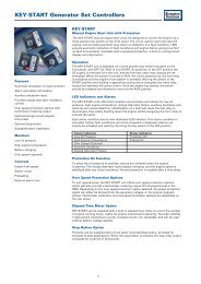
ACTUATOR SPECIFICATIONS<br />
Output Shaft............................................500-36 (inch) serration on output shaft. Side opposite linkage used for return<br />
spring.<br />
Operating Temperature Range.............–34 to +100 °C (–30 to +212 °F).<br />
Construction ..........................................Aluminum and steel parts. All parts treated for corrosion resistance. Not painted.<br />
Sealed bearings and low moving mass provide long service-free life.<br />
Weight.....................................................The 4024 actuator weighs about 18 kg (40 lb).<br />
Vibration Tested ....................................Tested to US Mil-Std-810C, curve T, 30 G. Shock tested to US Mil-Std 901C, 400<br />
lb hammer.<br />
Rotor design is ba<strong>la</strong>nced to minimize vibration-induced output-shaft motion.<br />
Electrical Characteristics......................Resistance 1.4 ±14 ! at 20 °C.<br />
Inductance +45 mH at 500 Hz.<br />
Current=7 A maximum continuous, 10 A maximum transient.<br />
Return Spring.........................................With actuator at 0°, return-spring torque is at 1.1 N·m (10 lb-in). With actuator at<br />
42°, return-spring torque is at 11.3 N·m (100 lb-in).<br />
4024 Actuator Outline (CCW version shown)
EPG CONTROL SPECIFICATIONS<br />
Speed Range<br />
A switch selects one of the following ranges (rating is<br />
based on frequency of sensed gear not necessarily engine<br />
rpm):<br />
750 to 1500 Hz<br />
1200 to 3000 Hz<br />
2800 to 6000 Hz<br />
5800 to 12 000 Hz<br />
7500 to 15 000 Hz<br />
Response<br />
Response of the controls is different for diesel and gas<br />
turbine applications than for gasoline and gas fueled<br />
(spark ignited) engines.<br />
Fuse and Wiring<br />
4 mm² (12 AWG) stranded wire used to connect the<br />
battery source to the control and the control to the<br />
actuator. Wire must be as short as possible, total distance<br />
from battery to control and from control to actuator not to<br />
exceed 6.7 m (22 ft). A 15 A fuse is required between<br />
battery and control.<br />
Battery<br />
Voltage source must be between 18 and 32 Vdc. Leads<br />
from battery to the control must be direct and not pass<br />
through any distribution points.<br />
Magnetic Pickup<br />
Must provide 1.5 Vrms minimum and at least 10% of rated<br />
speed while cranking.<br />
Magnetic pickup device is avai<strong>la</strong>ble from <strong>Woodward</strong>.<br />
Steady State Speed Band<br />
The control typically maintains ±0.250 of 1% of rated<br />
speed.<br />
Ambient Temperature Range<br />
–40 to +75 °C (–40 to +167 °F)<br />
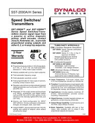
4024 Control Box Outline<br />
4024 PART NUMBERS<br />
Actuator<br />
Model 4024, 24 Vdc, CW output ...................................................................................................................... 8256-060<br />
Model 4024, 24 Vdc, CCW output.................................................................................................................... 8256-080<br />
Model 4024, 24 Vdc, with position feedback, CW output................................................................................. 8256-097<br />
Model 4024, 24 Vdc, with position feedback, CCW output .............................................................................. 8256-100<br />
Speed Control (Isochronous)<br />
Model 4024, 24 Vdc, speed control for natural gas or gasoline, with start fuel limit......................................... 8290-147<br />
Model 4024, 24 Vdc, speed control for diesel or turbine, with start fuel limit ................................................... 8290-148<br />
Driver/Wiring Harness/Linkage Kit<br />
Model 4024 Actuator Driver, 1–5 Vdc or 4–20 mA input .................................................................................. 8290-153<br />
Wiring Harness for Model 4024 with position feedback, low profile kit ............................................................ 8293-538<br />
Wiring Harness for Model 4024 with position feedback, low profile harness ................................................... 5416-985<br />
General Linkage Kit for Model 4024 (1 lever [3699-027], 2 rod ends) ............................................................. 8293-093<br />
Lever for Model 4024, EG-10P (.5x36 serrations)............................................................................................ 3699-027<br />
Instal<strong>la</strong>tion Kits<br />
Caterpil<strong>la</strong>r Engine, 3408, 3412, Speed Setting Lever ...................................................................................... 8924-743<br />
Detroit Diesel Engine, V71 16 cylinder or V92 12/16 cylinder.......................................................................... 8923-072<br />
Detroit Diesel Engine, V149 ............................................................................................................................. 8923-071<br />
Detroit Diesel Engine, 24V71 ........................................................................................................................... 8923-383
<strong>Woodward</strong>/<br />
Industrial Controls<br />
PO Box 1519<br />
Fort Collins CO, USA<br />
80522-1519<br />
1000 East Drake Road<br />
Fort Collins CO 80525<br />
Ph: (1)(970) 482-5811<br />
Fax: (1)(970) 498-3058<br />
Distributors & Service<br />
<strong>Woodward</strong> has an<br />
international network of<br />
distributors and service<br />
facilities. For your nearest<br />
representative call<br />
(1)(800) 835-5182 or see the<br />
Worldwide Directory on our<br />
web site.<br />
Corporate Headquarters<br />
Rockford IL, USA<br />
Ph: (1)(815) 877-7441<br />
www.woodward.com<br />
P<strong>la</strong>nt Wiring Diagram<br />
This document is distributed for<br />
informational purposes only. It is<br />
not to be construed as creating or<br />
becoming part of any <strong>Woodward</strong><br />
Governor Company contractual or<br />
warranty obligation unless<br />
expressly stated in a written sales<br />
contract.<br />
For more information contact:<br />
© <strong>Woodward</strong> Governor<br />
Company, 1991<br />
All Rights Reserved<br />
00/11/F