Chapter 11 Communication of FBs-PLC - Alstron
Chapter 11 Communication of FBs-PLC - Alstron
Chapter 11 Communication of FBs-PLC - Alstron

You also want an ePaper? Increase the reach of your titles
YUMPU automatically turns print PDFs into web optimized ePapers that Google loves.
<strong>Chapter</strong> <strong>11</strong><br />
<strong>Communication</strong> <strong>of</strong> <strong>FBs</strong>-<strong>PLC</strong><br />
The <strong>FBs</strong>-<strong>PLC</strong> main unit has been built in the communication port0 with optional USB or RS232 interface. If additional<br />
communication boards (CB) have been purchased, then it can increase to 2~3 communication interfaces (depending on<br />
the model <strong>of</strong> CB). If it is still not enough, communication modules can be added to expand the number <strong>of</strong> communication<br />
interfaces to 5 (PORT0~PORT4). There are three types <strong>of</strong> communication interfaces, RS232、RS485 or Ethernet, to<br />
choose from in both CB and CM. Among them, Port 0 is a permanent interface for FATEK communications interface,<br />
which is controlled by the CPU <strong>of</strong> the <strong>PLC</strong>, using FATEK “Standard communication driver” to manage the communication<br />
transactions <strong>of</strong> the Port, i.e. “FATEK communication protocol”. Any access to the Port must comply with the format <strong>of</strong><br />
“FATEK communication protocol” to get responses from the <strong>PLC</strong>. This includes starting character, station no., command<br />
code, body, error check code, ending characters, etc.; for more details please refer to “Appendix 2: FATEK communication<br />
protocol”. WinProladder and numerous HMI and SCADA s<strong>of</strong>twares are equipped with communication drivers complying<br />
with this communication protocol, therefore where the parameters on hardware interface and communications are<br />
consistent, communication connection can be established by just connecting the communication Port with the “Standard<br />
Interface”. If the communication driver with complying communication protocol is not available, besides writing its own<br />
commands complying with “FATEK communication protocol” to communicate with <strong>PLC</strong>, the commonly used industrial<br />
ModBus RTU protocol can also be used to establish a connection with <strong>FBs</strong>-<strong>PLC</strong>. The factory setting and the <strong>PLC</strong> system<br />
initialization on Port 1 ~ Port 4 default to FATEK standard communication interface; though in order to meet the extensive<br />
application and requirements <strong>of</strong> communication connection, Port 1 ~ Port 4 provides FATEK standard communication<br />
interface, as well as providing easy communication commands that support powerful functions to allow users to compile<br />
their required communication application s<strong>of</strong>tware through the Ladder diagram program, and easily achieve the aim <strong>of</strong><br />
system integration and distributed monitoring. Further detail will be explained in subsequent chapters.<br />
<strong>11</strong>.1 Functions and applications <strong>of</strong> <strong>FBs</strong>-<strong>PLC</strong> communication ports<br />
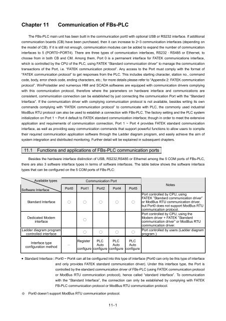
Besides the hardware interface distinction <strong>of</strong> USB, RS232,RS485 or Ethernet among the 5 COM ports <strong>of</strong> <strong>FBs</strong>-<strong>PLC</strong>,<br />
there are also 3 s<strong>of</strong>tware interface types in terms <strong>of</strong> s<strong>of</strong>tware interfaces. The table below shows the s<strong>of</strong>tware interface<br />
types that can be configured on the 5 COM ports <strong>of</strong> <strong>FBs</strong>-<strong>PLC</strong>:<br />
Available types<br />
S<strong>of</strong>tware Interface<br />
<strong>Communication</strong> Port<br />
Port0 Port1 Port2 Port4 Port5<br />
Standard Interface ○ ○ ○ ○ ○<br />
Dedicated Modem<br />
interface<br />
Ladder diagram program<br />
controlled interface<br />
○<br />
○ ○ ○ ○<br />
Notes<br />
Port controlled by CPU, using<br />
FATEK ”Standard communication driver”<br />
or ModBus RTU communication driver,<br />
but Port0 does not support ModBus RTU<br />
communication protocol.<br />
Port controlled by CPU, using the<br />
Modem driver + FATEK ”Standard<br />
communication driver” or ModBus RTU<br />
communication driver.<br />
Port controlled by users (Ladder diagram<br />
program )<br />
Interface type<br />
configuration method<br />
-<br />
Register<br />
configure<br />
<strong>PLC</strong><br />
Auto<br />
configure<br />
<strong>PLC</strong><br />
Auto<br />
configure<br />
<strong>PLC</strong><br />
Auto<br />
configure<br />
• Standard Interface : Port0 ~ Port4 can all be configured into this type <strong>of</strong> interface (Port0 can only be this type <strong>of</strong> interface<br />
and only provides FATEK standard communication driver). Under this interface type, the Port is<br />
controlled by the standard communication driver <strong>of</strong> <strong>FBs</strong>-<strong>PLC</strong> (using FATEK communication protocol<br />
or ModBus RTU communication protocol), hence called “standard interface”. To communication<br />
with the “Standard Interface”, the connection can only be established by complying with FATEK<br />
FB-<strong>PLC</strong> communication protocol or ModBus RTU communication protocol.<br />
※ Port0 doesn’t support ModBus RTU communication protocol.<br />
<strong>11</strong>-1
• Dedicated Modem Interface : Only Port1 can select this interface type. Under this interface type, Port1 is controlled by<br />
the built-in “MODEM driver” <strong>of</strong> <strong>FBs</strong>-<strong>PLC</strong>, in charge <strong>of</strong> telephone reception or dialing tasks,<br />
and then hand the connection over to FATEK standard communication driver after the<br />
connection is established, subsequent operation is the same as the “Standard interface”<br />
above.<br />
• Ladder diagram Program controlled interface : Port1 ~ Port4 can all select this interface type. Under this interface type,<br />
the Port will be controlled by the user’s Ladder diagram program<br />
instructions, such as FUN94, FUN150, FUN151, etc., hence users can<br />
gain control <strong>of</strong> the Port through the Ladder program.<br />
The following sections will detail the functions and applications <strong>of</strong> the 5 Ports on <strong>FBs</strong>-<strong>PLC</strong> under each <strong>of</strong> the 3<br />
different s<strong>of</strong>tware interfaces.<br />
* Port0 ~ Port4 communication parameter are default to :<br />
Baud Rate: 9600 bps<br />
Data Length: 7 Bits<br />
Parity: Even<br />
Stop Bit: 1 Bit<br />
<strong>11</strong>.1.1 <strong>Communication</strong> port 0 : USB or RS232 interface<br />
Functional specification<br />
• USB interface complies with standard functional specification <strong>of</strong> USB1.1<br />
• RS232 interface functional specification complies with the EIA RS232 standard, with 5 types <strong>of</strong> communication<br />
speeds 9600, 19200, 38400, 57600 and <strong>11</strong>5200 configurable.<br />
Basic usage<br />
• Besides providing the standard RS232 interface, models with USB interface are also provided since more and more<br />
notebook computers are using USB port to replace COM ports due to light weight and thickness considerations.<br />
• The main purpose <strong>of</strong> Port0 is to provide a communication interface for program editing, so generally speaking it would<br />
be in passive receiving mode.<br />
Extended usage<br />
Besides program editing, it can also connect to HMI, SCADA equipped with FATEK communication driver.<br />
Through conversion <strong>of</strong> interface signal into RS485 signal, connections can be made with RS485 interface<br />
peripherals, such as computers, WinProladder, HMI, SCADA, etc. or become a Slave <strong>of</strong> the FATEK CPU Link<br />
network.<br />
<strong>11</strong>.1.2 <strong>Communication</strong> port1~port4 : RS232 or RS485 interface<br />
Functional specification<br />
• RS232 interface functional specification complies with the EIA RS232C standard, communication parameters are<br />
adjustable up to highest communication rate <strong>of</strong> 921.6Kbps. Factory setting and system initialization communication<br />
parameter is configured to the default communication parameter.<br />
• RS485 interface functional specification complies with EIA RS485 standard.<br />
<strong>11</strong>-2
Basic usage<br />
There are 3 types <strong>of</strong> s<strong>of</strong>tware interface are selectable as follows :<br />
Standard interface :<br />
Connectable to peripherals with RS232 or RS485 interface, such as computer, WinProladder, HMI, SCADA, etc.<br />
Port1 dedicated modem interface :<br />
It can actively or passively connect to remote computers or conduct auto information gathering, warning, anomaly<br />
reporting or dial B.B. call for remote servicing via MODEM.<br />
Ladder diagram Program controlled interface :<br />
User can control Port1~Port4 through the ladder diagram instructions, such as FUN94 (ASCWR) command to take<br />
control <strong>of</strong> Port1 and connect to printers with RS232 hardware interface for Chinese/English report printing; FUN151<br />
(CLINK) command takes control <strong>of</strong> Port1~Port4 to establish connection with FATEK CPU Link or peripherals with<br />
RS232 or RS485 interfaces; FUN150 (MBUS) command can turn Port1~Port4 into a master <strong>of</strong> ModBus RTU<br />
communication protocol for connecting Slaves with this communication protocol.<br />
Port2 can provide FATEK high speed CPU Link function.<br />
Extended usage<br />
• Under Standard interface, act as the Slave for multi-drop FATEK RS485 or point to point RS232 CPU LINK network.<br />
• Under Ladder diagram program controlled interface types, Port1~Port4 has the following functions:<br />
Use MD0 mode <strong>of</strong> FUN151 (CLINK) instruction to act as the master for FATEK CPU Link network.<br />
Use MD1 mode <strong>of</strong> FUN151 (CLINK) instruction to actively connect to intelligent peripherals equipped with this<br />
communication interface, such as other brands’ <strong>PLC</strong>, servo driver, temperature controller, inverter, message<br />
display, etc.<br />
Use MD2 mode <strong>of</strong> FUN151 (CLINK) instruction for connection to receive the intelligent peripherals equipped with<br />
this communication interface, such as card readers, bar code readers, weighing scales, etc.<br />
Port2 can utilize MD3 mode <strong>of</strong> FUN151 (CLINK) instruction to act as the master for FATEK high speed CPU Link<br />
network.<br />
Use FUN150 (MBus) instruction to act as the Master for ModBus RTU communication protocol to connect to<br />
peripherals with this communication protocol.<br />
<strong>11</strong>.1.3 Ethernet interface<br />
Functional specification<br />
• Comply with IEEE802.3 standard to provide 10Base T interface.<br />
Basic usage<br />
• Provide intranet or internet connectivity within the plant. It can connect to WinProladder, HMI, SCADA with Ethernet<br />
network interface and FATEK communications driver or ModBus driver.<br />
<strong>11</strong>-3
Extended usage<br />
• It can coordinate with MD0 mode <strong>of</strong> FUN151(CLINK) instruction to provide remote data acquisition through the<br />
Ethernet network between the <strong>PLC</strong>’s. ( * Client Mode).<br />
Note : For details on Client Mode <strong>of</strong> <strong>FBs</strong>-<strong>PLC</strong> network interface, please refer to the explanations in section <strong>11</strong>.8.5.2.<br />
<strong>11</strong>.2 How to use <strong>FBs</strong>-<strong>PLC</strong> communication functions<br />
Refer to the diagram in Section 2.2 “Combination <strong>of</strong> <strong>PLC</strong> and Peripheral Systems” in the “Hardware Manual” for the<br />
connection <strong>of</strong> <strong>FBs</strong>-<strong>PLC</strong> to the host computer, intelligent peripherals, and other <strong>PLC</strong>s.<br />
Among Port0~Port4, only Port 2 provides real-time response function (real-time: data is processed immediately<br />
when received or sent without being affected by scan time.) and communicates with binary code (two times ASCII code).<br />
Other ports use ASCII code for communication in the standard mode and data will not be processed until the scan is<br />
complete and housekeeping is active. Thus, there will have the service delay because <strong>of</strong> the scan time. Port2 should be<br />
provided for each <strong>PLC</strong> to share data with each other via “FATEK high-speed CPU Link” (i.e., the MD3 mode <strong>of</strong> FUN151<br />
(CLINK) ) to meet the real time monitor requirements. Port0, Port1, Port3, Port4 should be used for intelligent peripherals,<br />
HMI, SCADA, and other non-real-time control applications for data collection and monitoring.<br />
<strong>11</strong>.3 Hardware wiring notifications for RS485 interface<br />
In the <strong>FBs</strong>-<strong>PLC</strong> communication interfaces, RS232 provides only point to point connection function while RS485<br />
provides connection for multiple stations. Its wiring distance should conform to the restriction specified in the EIA standard.<br />
The principle that connection distance should be as short as possible and the station should be far away from high<br />
noise sources must be observed for hardware wiring. RS232 is for point to point connection with a shorter connection<br />
distance and the standard cable sold in the market or provided by FATEK is applicable. However, for high-speed RS485<br />
network, communication quality is affected and operation might be seriously interfered with if the problems, such as high<br />
baud rate, long connection distance, high signal attenuation, multiple stations, bad grounding, high noise, terminating<br />
impedance mapping, and topology, are not solved appropriately. Please read the notes <strong>of</strong> hardware wiring for RS485<br />
network at the end <strong>of</strong> this section carefully.<br />
Limits on the number <strong>of</strong> stations<br />
Though the number <strong>of</strong> <strong>FBs</strong>-<strong>PLC</strong> stations can be set up to 254, 16 stations are the maximum for hardware driving for<br />
RS485 interface. If more than 16 stations are required, a RS485 amplifier (<strong>FBs</strong>-CM5R) must be used. 16 additional<br />
stations can be assigned to one amplifier up to the max. 254 stations.<br />
Max. 254 station <strong>of</strong> <strong>PLC</strong><br />
FBS-<strong>PLC</strong><br />
FBS-<strong>PLC</strong> FBS-<strong>PLC</strong> FBS-<strong>PLC</strong> FBS-<strong>PLC</strong> FBS-<strong>PLC</strong> FBS-<strong>PLC</strong><br />
#1 #2<br />
#16 #17 #18 #32<br />
#254<br />
RS485 RS485 RS485<br />
FBS-CM5R<br />
FBS-CM5R<br />
Max. 16 station<br />
<strong>of</strong> <strong>PLC</strong><br />
Max. 16 station<br />
<strong>of</strong> <strong>PLC</strong><br />
<strong>11</strong>-4
Limit on distance<br />
The following diagram shows the relationship between the baud rate and transmission distance <strong>of</strong> RS485 standard<br />
interface.<br />
10K<br />
Transmission Distance<br />
4K<br />
1K<br />
( )<br />
feet<br />
100<br />
40<br />
40<br />
40 100K 1M 10M<br />
Baud Rate (bps)<br />
Cable<br />
Use the shielded twisted pair cables for connection. Cable quality is an important factor to transmission signal. When<br />
the baud rate is high, low quality twisted pair (e.g., PVC twisted pair cables) will cause extremely high signal attenuation<br />
and considerably shorten the transmission distance. Its noise immunity is poorer. In a circumstance where the baud rate<br />
and noise is high, and the distance is long, use high quality twisted pair cables (such as Belden 9841 polyethylene twisted<br />
pair cables), Its dielectric loss can be 1000 times lesser than that <strong>of</strong> PVC twisted pair cable. But in a circumstance where<br />
the baud rate and noise are low, PVC twisted pair cable is an acceptable and economical alternative. If the transmission<br />
distance is too long to raise signal attenuation, use a RS485 amplifier (<strong>FBs</strong>-CM5R) to amplify signal.<br />
Topology<br />
Topology is a graph structure <strong>of</strong> transmission connection. The topology <strong>of</strong> RS485 must be in a Bus structure. All<br />
cables must be connected from the first station to the second station, from the second station to the third station, …… to<br />
the last station. As shown in the following diagrams, both star and ring connections are not allowed. If <strong>FBs</strong>-CM5H is used,<br />
RS485 can be set to star connection, but ring connection is still not allowed.<br />
BUS connection<br />
the shorter<br />
the better<br />
the shorter<br />
the better<br />
D D F D D F<br />
_ RS485<br />
_ RS485<br />
D D F<br />
+ G<br />
+ G<br />
+<br />
_<br />
G<br />
RS485<br />
<strong>11</strong>-5
星 Star 狀 連 接 ( 不 允 許 )<br />
connection<br />
D D F<br />
+ _<br />
G<br />
RS485<br />
D F _<br />
G RS485<br />
D F<br />
_ G RS485<br />
D D F<br />
+ _<br />
G RS485<br />
D<br />
+<br />
D<br />
+<br />
D<br />
+<br />
環 Ring 狀 連 接 ( 不 允 許 )<br />
connection<br />
D F<br />
_<br />
G<br />
RS485<br />
D +<br />
D<br />
_<br />
F G<br />
RS485<br />
D +<br />
D _<br />
F G<br />
RS485<br />
D D F<br />
+<br />
_<br />
G<br />
RS485<br />
RS485<br />
D D F<br />
_<br />
+ G<br />
RS485<br />
D D F<br />
+ _ G<br />
RS485<br />
D D F<br />
G<br />
D F<br />
_ G<br />
D<br />
+<br />
RS485<br />
RS485<br />
RS485<br />
+ _ D D F<br />
+<br />
_<br />
D D F<br />
G<br />
G<br />
RS485 network can<br />
collocate with<br />
RS-485 <strong>FBs</strong>-CM5H 網 路 搭 配 to FBS-CM5H be Star<br />
connection 即 可 配 成 星 狀 連 結<br />
FG<br />
IN 24- GND1CH2+<br />
CH2-<br />
24+ CH1+ CH1- GND2<br />
FBS-CM5H<br />
CH3+ CH3- GND4<br />
FG<br />
GND3 CH4+ CH4-<br />
FG<br />
D D F<br />
+<br />
_<br />
G<br />
D D F<br />
+<br />
_<br />
G<br />
D D F<br />
+<br />
_<br />
G<br />
+ _ G<br />
FG<br />
D D F<br />
D D F<br />
+<br />
_<br />
+<br />
_<br />
G<br />
D D F<br />
+<br />
_<br />
G<br />
RS485<br />
RS485<br />
RS485<br />
RS485<br />
RS485<br />
RS485<br />
<strong>11</strong>-6
FG grounding<br />
Though RS485 network can be connected with two cables, the connection is easily affected by noise. To improve<br />
communication quality, the ground potential difference (common mode voltage) between two stations should not exceed<br />
the max. allowable common mode voltage <strong>of</strong> the R485 transmission IC. 7V shall not be exceeded when <strong>FBs</strong>-<strong>PLC</strong> IC is<br />
used; otherwise, RS485 may not operate normally.<br />
D D F<br />
+<br />
_ G<br />
Place A<br />
Ecom<br />
7V<br />
D D F<br />
+<br />
_ G<br />
Place B<br />
No matter how the ground potential is, we recommend using a twisted pair cable covered with shielding. The FG <strong>of</strong><br />
each station is connected with the ground wire covered with shielding (similar to the above-mentioned ”topology”) to clear<br />
common mode voltage and provides the shortest circuit for signal transmission to improve the anti-noise capacity.<br />
Terminating impedance<br />
Different transmission cables have different characteristic impedance (the characteristic impedance <strong>of</strong> a twisted pair<br />
cable is approximately 120Ω). When the signal is transmitted to the terminating resistor <strong>of</strong> a cable, reflection and waveform<br />
distortion (either sinking or protruding) will be caused if the terminating impedance is different from its characteristic<br />
impedance. This distortion is not obvious when the cable is short but it will be more serious with longer cables. Finally,<br />
<strong>PLC</strong>s cannot transmit correctly and a terminating resistor should be installed to solve this problem. A 120Ω terminating<br />
resistor has been installed inside the <strong>FBs</strong>-<strong>PLC</strong>. When a terminating resistor is required to be added, open the cover and<br />
toggle the DIP switch to the “ON” position (DIP switch is set to “OFF” position by the factory). Terminating resistors can<br />
only be added to each <strong>PLC</strong> on the utmost left and right ends <strong>of</strong> the Bus. All the DIP switches between both end should be<br />
on the position “OFF”, or the driving power <strong>of</strong> RS485 may become insufficient. The diagram below shows the setting and<br />
application <strong>of</strong> terminating resistors:<br />
(The end<br />
<strong>of</strong> left<br />
station)<br />
D D F<br />
+<br />
T<br />
N<br />
ON<br />
SW<br />
1 2<br />
D D F<br />
+<br />
T<br />
N<br />
ON<br />
SW<br />
1 2<br />
adjust to "OFF"<br />
D D F<br />
+<br />
T<br />
N<br />
ON<br />
SW<br />
1 2<br />
D D F<br />
+<br />
T<br />
N<br />
ON<br />
SW<br />
1 2<br />
(The end<br />
<strong>of</strong> right<br />
station)<br />
Should open the <strong>PLC</strong>'s cover, cover, adjust adjust to “ON” to "ON" for most for most left left and and right right <strong>PLC</strong> <strong>PLC</strong> units. units.<br />
<strong>11</strong>-7
Strategies against noise<br />
When wiring for RS485 network is implemented based on the described materials and rules or a 120Ω terminating<br />
resistor is added, most noise situations are eliminated. However, if noise cannot be eliminated, it means that there are<br />
strong noise sources near the RS485 network. Besides keeping cables far away from noise sources (e.g., electromagnetic<br />
valves, inverters, servo drivers, or other power units), the most effective way to solve the problem is to use noise<br />
suppression components. Refer to the description in Section 7.5 in the “Hardware Manual” for noise suppression <strong>of</strong><br />
electromagnetic valves, relays and other devices with inductive load. The diagram below shows the noise suppression<br />
approaches for inverters, servo drivers, and other high-noise power units (i.e., add X capacitance or Y capacitance or X+Y<br />
capacitance).<br />
R<br />
S<br />
T<br />
W<br />
C<br />
C<br />
C<br />
C<br />
C<br />
C<br />
C<br />
C<br />
C C C<br />
C<br />
R S T<br />
(Add X<br />
capacitor)<br />
R S T W R S T W<br />
(Add Y<br />
capacitor)<br />
(Add X+Y<br />
capacitor)<br />
C = 0.22µf~0.47µf/AC630V<br />
Caution<br />
• Hardware wiring for communication network and addition and removal <strong>of</strong> communication stations<br />
should be implemented with <strong>PLC</strong> disconnected. Don’t work especially when <strong>PLC</strong> is running, or<br />
communication errors may occur to generate incorrect <strong>PLC</strong> output.<br />
<strong>11</strong>.4 How to use <strong>FBs</strong>-<strong>PLC</strong> communication ports<br />
The requirements for communication are that (1) hardware interfaces and mechanisms, (2) communication<br />
parameters and (3) s<strong>of</strong>tware interfaces (i.e. the protocol) <strong>of</strong> the receiver/ sender must be consistent. The same are<br />
applicable to <strong>PLC</strong>. After the above three fundamentals are meet, <strong>PLC</strong> will communicate with other <strong>PLC</strong>s or peripherals.<br />
The following will describe these three fundamentals.<br />
<strong>11</strong>.4.1 Matching <strong>of</strong> hardware interfaces and mechanisms<br />
In order to meet the interface requirement <strong>of</strong> variety peripherals, the <strong>FBs</strong>-<strong>PLC</strong> provides USB, RS232, RS485 and<br />
Ethernet communication interfaces for choice. When install, care should be taken if the hardware interface is <strong>of</strong> the same<br />
type. Incorrect connection <strong>of</strong> different type <strong>of</strong> communication interface may cause the permanent hardware failure. Also<br />
please make sure that the signals <strong>of</strong> mating connector are all match. For example, TXD must connect to RXD, RTS (if any)<br />
should be connected to CTS. The interface <strong>of</strong> USB, RS232 and RS485 are described at bellow (Ethernet is described at<br />
section 1.8).<br />
<strong>11</strong>-8
Port0 USB interface (built in)<br />
The <strong>FBs</strong>-<strong>PLC</strong> equipped with port0 USB interface can be order by suffixed an U letter in the CPU model number. The<br />
port0 can only be acted as slave. Its connector is a standard USB B type connector. The user can use the standard USB A<br />
to USB B cable (can buy from FATEK, the product number is <strong>FBs</strong>-USBP0-180, please refer the description at below) to<br />
connect the PC and <strong>PLC</strong>.<br />
Port0 RS232 interface (built in)<br />
The CPU model number with no U letter suffixed is a <strong>FBs</strong>-<strong>PLC</strong> that built in a port0 RS232 interface. The connector<br />
for port0 RS232 is a 4 pin Mini-DIN female connector. FATEK provides a dedicated connection cable that has a 9 Pin<br />
D-sub female connector at one end for the PC or peripherals to connect <strong>PLC</strong> port0 RS232. The wiring diagrams <strong>of</strong> port0<br />
USB and RS232 connection cable are shown at below.<br />
<strong>FBs</strong>-232P0-9F-150 (Mini-DIN male 9 Pin D-sub female) :<br />
Female<br />
9<br />
8<br />
7<br />
6<br />
5<br />
4<br />
3<br />
2<br />
1<br />
GND<br />
RXD<br />
TXD<br />
+5V<br />
Mini-DIN<br />
(<strong>PLC</strong> Side)<br />
Male<br />
2<br />
4<br />
1<br />
3<br />
<strong>FBs</strong>-232P0-9M-400 (Mini-DIN male 9 Pin D-sub male) :<br />
6<br />
7<br />
8<br />
9<br />
Male<br />
1<br />
2<br />
3<br />
4<br />
5<br />
GND<br />
RXD<br />
TXD<br />
+5V<br />
Mini-DIN<br />
(<strong>PLC</strong> Side)<br />
Male<br />
2<br />
4<br />
1<br />
3<br />
Model<br />
Description<br />
<strong>FBs</strong>-232P0-9F-150 Dedicated for <strong>FBs</strong> RS232 Port 0 to 9Pin D-sub female, 150cm long.<br />
<strong>FBs</strong>-232P0-9M-400 Dedicated for <strong>FBs</strong> RS232 Port0 to 9Pin D-sub male, 400cm long.<br />
<strong>FBs</strong>-USBP0-180 Port0 USB cable (standard commercial USB A B), 180cm long.<br />
<strong>11</strong>-9
F B s − 2 3 2 P 0 − 9 F − 1 5 0<br />
<strong>FBs</strong>-Series product<br />
name<br />
(connector specification) (connection distance) unit/cm<br />
F: Female<br />
M: Male<br />
9: 9Pin D-sub<br />
Port on<br />
( the <strong>PLC</strong> )<br />
External<br />
( Interface )<br />
P0:Port0 (RS232)<br />
P0:Port0 (USB)<br />
232:RS232<br />
USB:USB1.1<br />
Port1~Port4 RS232 interface (expandable)<br />
The communication port <strong>of</strong> Port1~Port4 can be utilized by installed the RS232 communication board (or module).<br />
Each communication board (or module) provides one or two standard RS232 9 Pin D-sub female connector(s). While<br />
application, the user can buy a standard 9 pin RS232 cable directly from computer store or follow the example diagram at<br />
below to DIY the cable.<br />
Connector Type<br />
Pin<br />
Signal Name<br />
TXD RXD RTS CTS SG DTR DSR<br />
9Pin MALE 3 2 7 8 5 4 6<br />
D-sub FEMALE 2 3 8 7 5 6 4<br />
port1、port2 usage only<br />
<strong>FBs</strong> <strong>PLC</strong> Non-usage<br />
9P D-sub female 9P D-sub male RS232 communication cable :<br />
Female<br />
Male<br />
9<br />
8<br />
7<br />
6<br />
5<br />
4<br />
3<br />
2<br />
1<br />
6<br />
7<br />
8<br />
9<br />
1<br />
2<br />
3<br />
4<br />
5<br />
<strong>11</strong>-10
9P D-sub male 9P D-sub male RS232 communication cable :<br />
Male<br />
Male<br />
6<br />
7<br />
8<br />
9<br />
1<br />
2<br />
3<br />
4<br />
5<br />
6<br />
7<br />
8<br />
9<br />
1<br />
2<br />
3<br />
4<br />
5<br />
If you make RS232 cables by yourself and the definition <strong>of</strong> each pin is not clear, use a multimeter for measurement to<br />
determine TXD and RXD.<br />
9 Pin connector: The pin 5 is SG;<br />
Measure the pin 2 (red probe) and the pin 5 (black probe) with a multimeter. If it is approximately<br />
−9V, it means that the pin 2 is the transmission pin; If it is approximately 0V, it means that the pin 2 is the<br />
receiving pin.<br />
Measure the pin 3 (red probe) and the pin 5 (black probe) by a multimeter. If it is approximately<br />
−9V, it means that the pin 3 is the transmission pin; If it is approximately 0V, it means that the pin 3 is the<br />
receiveing pin.<br />
Port1~Port4 RS485 interface (expandable)<br />
The communication port <strong>of</strong> Port1~Port4 can be utilized by installed the RS485 communication board (or module).<br />
Each communication board (or module) provides one or two standard RS485 3-pin European plug-able terminal block. The<br />
pin assignment <strong>of</strong> connector(s) is show below.<br />
+ (D+)<br />
(D )<br />
G (FG)<br />
<strong>11</strong>.4.2 Selection and setting <strong>of</strong> communication protocols<br />
Besides <strong>of</strong>fering the FATEK protocol by default, Port1~Port4 can be set to ModBus (Slave) protocol. The following<br />
shows the setting steps in the WinProladder :<br />
Click the protocol:<br />
<strong>PLC</strong><br />
Setting<br />
Protocol a port can be set to ModBus RTU or FATEK Protocol:<br />
<strong>11</strong>-<strong>11</strong>
Besides, you also can setting the communication protocol through special register.<br />
● R4047 : Upper Byte = 55H, configure the communication port for ModBus RTU protocol.<br />
= Other values, Port1~4 don’t support ModBus RTU protocol(The defaults are FATEK protocol)<br />
Lower Byte : Port assignment for ModBus RTU protocol.<br />
Format as below :<br />
Upper Byte<br />
Lower Byte<br />
55H b7 b6 b5 b4 b3 b2 b1 b0<br />
b0, Reserved ;<br />
b1=0, Port 1 acts as FATEK protocol.<br />
=1, Port 1 acts as ModBus RTU protocol.<br />
b2=0, Port 2 acts as FATEK protocol.<br />
=1, Port 2 acts as ModBus RTU protocol.<br />
b3=0, Port 3 acts as FATEK protocol.<br />
=1, Port 3 acts as ModBus RTU protocol.<br />
b4=0, Port 4 acts as FATEK protocol.<br />
=1, Port 4 acts as ModBus RTU protocol.<br />
●<br />
●<br />
●<br />
b5~b7, Reserved<br />
※ It allows to assign multiple ports for ModBus RTU protocol, where the corresponding bit must be 1.<br />
For example :<br />
R4047=5502H, Assign Port 1 as ModBus RTU protocol;<br />
R4047=5504H, Assign Port 2 as ModBus RTU protocol;<br />
R4047=5506H, Assign both Port 1 and Port 2 as ModBus RTU protocol;<br />
Refer to : The rule for address mapping between ModBus and Fatek(Page12-40).<br />
<strong>11</strong>-12
<strong>11</strong>.4.3 Settings for communication parameters<br />
<strong>Communication</strong> parameters can be set up for each <strong>of</strong> the 5 <strong>FBs</strong>-<strong>PLC</strong> ports. When out <strong>of</strong> factory or communication<br />
parameters <strong>of</strong> Port 0~Port 4 are set to the same parameters <strong>of</strong> Port 0 before shipment or after system initialization. (See<br />
the table below.)<br />
Baud Rate<br />
Data Length<br />
Parity Check<br />
Stop Bit<br />
9600 bps<br />
7 Bits<br />
Even<br />
1 Bit<br />
Default communication parameters<br />
Port<br />
Register<br />
Setup<br />
Default Value Default Baud Rate Other default Parameters<br />
Port 0 R4050 5621H 9600 bps 7-bit Data, Even、1-bit Stop<br />
Port 1 R4146 5621H 9600 bps 7-bit Data, Even、1-bit Stop<br />
Port 2 R4158 5621H 9600 bps 7-bit Data, Even、1-bit Stop<br />
Port 2<br />
(High-speed)<br />
R4161 5665H 153600 bps 8-bit Data, Even、1-bit Stop<br />
Port 3 R4043 5621H 9600 bps 7-bit Data, Even、1-bit Stop<br />
Port 4 R4044 5621H 9600 bps 7-bit Data, Even、1-bit Stop<br />
※ When a port is set to ModBus RTU protocol, data bit is always 8-bit.<br />
※ Port 1~Port 4 also provides Baud Rate settings for user-defined (<strong>11</strong>25 bps~<strong>11</strong>52000 bps).<br />
※ Port 0 can be changed the baud rate only the other parameters are always 7-bit Data, Even, 1-bit Stop.<br />
Also, Port 0 supports FATEK communication protocol only.<br />
<strong>11</strong>-13
Setup <strong>of</strong> port0~port4 communication parameters<br />
56H<br />
<strong>Communication</strong> Parameters<br />
B 15 B 8 B 7 B 0<br />
Even/Odd<br />
Parity<br />
0:Even Parity<br />
1:Odd Parity<br />
0:7 Bits<br />
Data Length 1:8 Bits ※R4161 is only 8-bit.<br />
Parity Check<br />
0:None Parity<br />
1:With Parity<br />
Stop Bit<br />
0:1 Bit<br />
1:2 Bits<br />
~ ~<br />
B7 B6 B5 B4 B3 B2 B1 B0<br />
<br />
Value<br />
Baud Rate<br />
0 0 0 0 0 4800 bps<br />
0 0 0 1 1 9600 bps<br />
0 0 1 0 2 19200 bps<br />
0 0 1 1 3 38400 bps<br />
0 1 0 0 4 76800 bps<br />
0 1 0 1 5 153600 bps<br />
0 1 1 0 6 307200 bps<br />
0 1 1 1 7 614400 bps<br />
1 0 0 0 8 7200 bps<br />
1 0 0 1 9 14400 bps<br />
1 0 1 0 A 28800 bps<br />
1 0 1 1 B 57600 bps<br />
1 1 0 0 C <strong>11</strong>5200 bps<br />
1 1 0 1 D 230400 bps<br />
1 1 1 0 E 921600 bps<br />
1 1 1 1 F User-defined<br />
※ R4161(PORT2)<br />
the high-speed<br />
baud rate must be<br />
greater than or<br />
equal 38400bps.<br />
<strong>11</strong>-14
Port 1~Port 4 provides Baud Rate settings for user-defined (<strong>11</strong>25 bps~<strong>11</strong>52000 bps)<br />
Formula<br />
18432000<br />
Baud_Rate_Div = ( ) -1 ( 15 ~ 16383 )<br />
Baud_Rate<br />
18432000<br />
Baud_Rate = (<br />
)<br />
Baud_Rate_Div + 1<br />
( <strong>11</strong>25 bps ~ <strong>11</strong>52000 bps )<br />
Port Register Setup Formula<br />
Port 1<br />
Port 2<br />
Port 3<br />
Port 4<br />
D4000<br />
D4001<br />
D4002<br />
D4003<br />
18432000<br />
D4000 = ( ) -1<br />
Baud_Rate<br />
18432000<br />
D4001 = ( ) -1<br />
Baud_Rate<br />
18432000<br />
D4002 = ( ) -1<br />
Baud_Rate<br />
18432000<br />
D4003 = ( ) -1<br />
Baud_Rate<br />
Example 1<br />
If you want to set Port 1 Baud Rate to 1200 bps, then R4146 = 56XFH :<br />
18432000<br />
D4000 = ( ) - 1 = 15359<br />
1200<br />
Example 2<br />
If you want to set Port 2 Baud Rate to 256000 bps, then R4158 = 56XFH :<br />
18432000<br />
D4001 = ( ) - 1 = 71<br />
25600<br />
<strong>11</strong>-15
Without station number checking for HMI or SCADA connecting<br />
While <strong>PLC</strong> communicating with WinProladder or Handheld PP, it recognizes the FATEK's internal communication<br />
protocol.<br />
While <strong>PLC</strong> communicating with Man Machine Interface (MMI) or Supervising s<strong>of</strong>tware (SCADA), it recognizes the<br />
FATEK's external communication protocol.<br />
Low byte <strong>of</strong> R4149 = 1, Port 0 without station number checking while FATEK's external communication protocol.<br />
Low byte <strong>of</strong> R4155 = 1, Port 1 without station number checking while FATEK's external communication protocol.<br />
High byte <strong>of</strong> R4155 = 1, Port 2 without station number checking while FATEK's external communication protocol.<br />
Low byte <strong>of</strong> R4156 = 1, Port 3 without station number checking while FATEK's external communication protocol.<br />
High byte <strong>of</strong> R4156 = 1, Port 4 without station number checking while FATEK's external communication protocol.<br />
Reply delay time setting<br />
As the <strong>PLC</strong> received a packet <strong>of</strong> addressed message and passed the error check, it would reply the message after<br />
the reply delay time period.<br />
Low byte <strong>of</strong> R4040 : Port 0 reply delay time setting (Unit in mS).<br />
High byte <strong>of</strong> R4040 : Port 1 reply delay time setting (Unit in mS).<br />
Low byte <strong>of</strong> R4041 : Port 2 reply delay time setting (Unit in mS).<br />
High byte <strong>of</strong> R4041 : Port 3 reply delay time setting (Unit in mS).<br />
Low byte <strong>of</strong> R4042 : Port 4 reply delay time setting (Unit in mS).<br />
Transmission delay time setting<br />
While the communication port being used as the master <strong>of</strong> FATEK CPU LINK (FUN151) or Modbus RTU (FUN150)<br />
multidrop's network, it allows the user to set the transmission delay time to slow down the expiration <strong>of</strong> message frame.<br />
High byte <strong>of</strong> R4147 : Port 1 transmission delay time setting (Unit in 10mS)<br />
High byte <strong>of</strong> R4159 : Port 2 transmission delay time setting (Unit in 10mS)<br />
High byte <strong>of</strong> R4045 : Port 3 transmission delay time setting (Unit in 10mS)<br />
High byte <strong>of</strong> R4048 : Port 4 transmission delay time setting (Unit in 10mS)<br />
Receive time-out span setting<br />
While the communication port being used as the master <strong>of</strong> FATEK CPU LINK (FUN151) or Modbus RTU (FUN150)<br />
multidrop's network, it allows the user to set the receive time-out span to detect whether the slave station on line or not.<br />
Low byte <strong>of</strong> R4147 : Port 1 receive time-out span setting (Unit in 10mS).<br />
Low byte <strong>of</strong> R4159 : Port 1 receive time-out span setting (Unit in 10mS).<br />
Low byte <strong>of</strong> R4045 : Port 1 receive time-out span setting (Unit in 10mS).<br />
Low byte <strong>of</strong> R4048 : Port 1 receive time-out span setting (Unit in 10mS).<br />
<strong>11</strong>-16
New message detection time interval setting<br />
1. While the communication port being used as the master or slave <strong>of</strong> Modbus RTU protocol,the system will give the<br />
default time interval to identify each packet <strong>of</strong> receiving message, if the default works not well, the user can set this time<br />
interval through the high byte setting <strong>of</strong> R4148 and let M1956 be 1, to avoid the overlap <strong>of</strong> different packet <strong>of</strong> message<br />
frame.<br />
When M1956=1 : High Byte <strong>of</strong> R4148 is used to set the new message detection time interval for Port 1~Port 4 (Unit in<br />
mS)<br />
2. While the communication port being used to communicate with the intelligent peripherals through the FUN151<br />
convenient instruction, if the communication protocol without the end <strong>of</strong> text to separate each packet <strong>of</strong> message frame,<br />
it needs message detection time interval to identify the different packet. High byte <strong>of</strong> R4148 is used for this setting.<br />
High Byte <strong>of</strong> R4148:New message detection time interval setting for Port 1~Port 4 (Unit in mS).<br />
Without station number checking for FATEK's internal communication protocol<br />
While <strong>PLC</strong> communicating with WinProladder or Handheld PP, it recognizes the FATEK's internal communication<br />
protocol, the quick way to communicate with the <strong>PLC</strong> is to key in 255 as the station number for WinProladder to connect<br />
with the unsured station number <strong>of</strong> target.<br />
When the number 255 for WinProladder to connect with the <strong>PLC</strong>, the <strong>PLC</strong> will communicate with Winproladder even<br />
the station number <strong>of</strong> <strong>PLC</strong> is 1~254.<br />
Related internal relay<br />
Port Port Ready Indicator Relay Finished Indicator Relay<br />
Port1 M1960 M1961<br />
Port2 M1962 M1963<br />
Port3 M1936 M1937<br />
Port4 M1938 M1939<br />
<strong>11</strong>.4.4 Modem interface setting<br />
High Byte <strong>of</strong> R4149 = 55H, Remote-Diagnosis/Remote-CPU-Link by way <strong>of</strong> Port 1 through Modem connection, it<br />
supports user program controlled dial up function.<br />
= AAH, Remote diagnosis by way <strong>of</strong> Port 1 through Modem connection, it supports Passive<br />
receiving & Active dialing operation mode<br />
= Other values, without above function<br />
<strong>11</strong>-17
<strong>11</strong>.5 Description and application <strong>of</strong> s<strong>of</strong>tware interface type<br />
<strong>11</strong>.5.1 Standard interface<br />
The port with the standard interface is controlled by <strong>PLC</strong> CPU, and the communication transaction <strong>of</strong> the ports is<br />
controlled by FATEK “Standard <strong>Communication</strong> Driver” or “ModBus <strong>Communication</strong> Driver”. All accesses to the port must<br />
be executed in the format <strong>of</strong> “FATEK-<strong>PLC</strong> Protocol” or “ModBus <strong>Communication</strong> Driver”. FP-07C, WinProladder s<strong>of</strong>tware<br />
package, and many HMI and SCADA have communication drivers conforming to “FATEK-<strong>PLC</strong> Protocol”, so linkage is built<br />
immediate when the “standard interface” port is connected and the hardware interface and communication parameters are<br />
consistent. When no such conforming communication driver is available, additional commands that conform to the format<br />
<strong>of</strong> “FATEK-<strong>PLC</strong> Protocol” or “ModBus <strong>Communication</strong> Driver” must be written for <strong>PLC</strong> communication.<br />
<strong>11</strong>.5.2 Modem-specific interface<br />
R4149 high byte = AAH means that Port 1 is set up to Modem-specific interface. Though CPU uses FATEK<br />
“Standard <strong>Communication</strong> Driver” or “ModBus <strong>Communication</strong> Driver” to control the communication transaction <strong>of</strong> Port 1,<br />
connection must be made via Modem. In other words, Port 1 is controlled by “Modem Driver” before communication starts,<br />
no matter whether active dialup or passive reception connection is concerned, and no access is allowed to <strong>PLC</strong>. The<br />
Modem Driver is only used for Modem connection and transfers the control <strong>of</strong> Port 1 to FATEK “Standard <strong>Communication</strong><br />
Driver” when Modem is connected successfully, and Port 1 becomes the “standard interface”. This section discusses the<br />
operation <strong>of</strong> Modem active dialup connection and passive reception connection.<br />
With the Modem-specific interface, the <strong>PLC</strong> allows Port 1 to dial up a remote Modem actively or receive messages<br />
from a remote Modem passively depending on the setting <strong>of</strong> the internal phone number register (R4140~R4145). When<br />
connection <strong>of</strong> both machines is successful, transmission or reception <strong>of</strong> data is executed via the phone cable.<br />
A. Passive reception mode<br />
When no “effective phone number” is stored in the internal phone number register <strong>of</strong> the <strong>PLC</strong> (see B below), it will<br />
enter the passive reception mode and set up the Modem to the reception mode waiting for a remote Modem to dial up.<br />
When both machines connect successfully and the inbound signal is correct, the <strong>PLC</strong> host exits the reception mode<br />
immediately and runs into connection state. The remote Modem can fully control and access the <strong>PLC</strong> host. The <strong>PLC</strong> host<br />
checks the content <strong>of</strong> the phone number register only at the moment when the power <strong>of</strong> the <strong>PLC</strong> host or Modem is turned<br />
on (OFF→ON). Therefore, any change to R4140~R4145 (e.g. save or removal <strong>of</strong> a phone number) is only effective when<br />
the power <strong>of</strong> the <strong>PLC</strong> host or Modem is turned <strong>of</strong>f and turned on again.<br />
B. Active dialup mode<br />
When an “effective phone number” is stored in the internal phone number register <strong>of</strong> the <strong>PLC</strong> host, it enters the<br />
active dialup mode at the moment when the power <strong>of</strong> the <strong>PLC</strong> host and Modem is turned on. In this mode, Port 1 can<br />
dialup a phone number in R4140~R4145 via Modem for connection to the remote Modem corresponding to this phone<br />
number. When both machines connect successfully, the <strong>PLC</strong> host exits the dialup mode and runs into connection state.<br />
The remote Modem can fully control and access the <strong>PLC</strong> host. If dialing fails, the <strong>PLC</strong> host executes the second dialing to<br />
a maximum <strong>of</strong> three redials (about 3 minutes). If the third redial fails, the <strong>PLC</strong> host exits the active dialup mode and enters<br />
the passive reception mode. It also sets up the Modem to the reception mode waiting for calls from a remote Modem.<br />
<strong>11</strong>-18
Only the phone number that is stored in the Modem phone number register in the following format will be identified as<br />
effective by the <strong>PLC</strong> host. The phone number must be written hex-decimally. Only 0~9 and “E” are meaningful in the<br />
hexadecimal digits. “A” stands for dialing delay and is usually used for international calls or extensions <strong>of</strong> an automatic<br />
switchboard. (a “A” is about 2 seconds). “B” stands for “#” (for B.B.Call), and “C” stands form “*”. Among the effective digits,<br />
0~9 is used for phone numbers, while “E” stands for the end <strong>of</strong> a phone number. Since each register has 4 hexadecimal<br />
digits, R4140~R4145 have 24 hexadecimal digits and maximum 23 digits, the end character “E” not counted, can be stored<br />
in R4140~R4145. Phone numbers are stored in order from digit 0 <strong>of</strong> R4140 to digit 3 <strong>of</strong> R4145. For example, the phone<br />
number 02-6237019 is stored in the following order:<br />
Direction<br />
R4145 R4144 R4143 R4142 R4141 R4140<br />
χ χ χ χ χ χ χ χ χ χ χ χ χ χ E 9 1 0 7 3 2 6 2 0<br />
↑<br />
↑<br />
↑<br />
↑<br />
↑<br />
Digit 3<br />
Digit 3<br />
End character<br />
Digit 3 Digit 0<br />
“χ”: Any value from 0 to F<br />
2620H is stored in R4140, 1073H is stored in R4141,and XXE9H is stored in R4142. R4143~R4145 can be any value.<br />
Please note that the last digit <strong>of</strong> the phone number must be followed by the end character “E”. The <strong>PLC</strong> host will ignore the<br />
number (any value from 0 to F) behind “E”. Only the value 0~C is acceptable before “E”. Any other values will be regarded<br />
as ineffective.<br />
If the telephone bill is paid by the service unit answering the call, no effect phone number should be stored in the<br />
internal Modem phone number register <strong>of</strong> the <strong>PLC</strong> host, so that it will enter the reception mode when turned on and the<br />
service unit will then call the client. If the phone bill is paid by the client, at least one effect phone number must be stored in<br />
the internal Modem phone number register <strong>of</strong> the <strong>PLC</strong> host, so that it will enter the dialup mode at the moment when the<br />
client turn on the power <strong>of</strong> the <strong>PLC</strong> host and Modem. Since the phone number <strong>of</strong> the service unit may change, the<br />
WinProladder package provides a phone number Write and Callback command. In this case, the client is not able to call<br />
the service unit with the old phone number. To solve this problem, the client may turn on the Modem and <strong>PLC</strong> host. When<br />
the <strong>PLC</strong> host fails converts to the reception mode after three failed dials (about 3 minutes), the service unit calls the client<br />
and imports its new phone number in the Modem phone number register <strong>of</strong> client’s <strong>PLC</strong> host and sends a callback<br />
command. When receiving the callback command, the <strong>PLC</strong> host <strong>of</strong> the client enters the dialup mode immediately and calls<br />
the service unit with the imported new number. This application requests the service unit to call the client and pay the bill.<br />
However, the amount <strong>of</strong> the telephone bill is limited because it takes very short time for implementation <strong>of</strong> the Write and<br />
Callback command.<br />
When executing the “Write and Callback” command and connecting to the host <strong>of</strong> the client successfully,<br />
WinProladder will take the old number back from the <strong>PLC</strong> host for reference (and for future use when write-back <strong>of</strong> the old<br />
number is required) before it writes the new number and executes callback. When the connection is not required any more,<br />
WinProladder will give a shutdown command automatically for disconnection.<br />
<strong>11</strong>-19
<strong>11</strong>.5.3 Ladder program control interface<br />
This type <strong>of</strong> interface can be set up for Port1~Port4. The ladder program that are used to control the ports are<br />
FUN94 (ASCWR), FUN150 (M-BUS) and FUN151 (CLINK).<br />
FUN94 (ASCWR) uses Port 1 as an output interface for ASCII files (transmission only) and sends messages to<br />
printers, computers, and other devices that receive messages with ASCII code. The typical application <strong>of</strong> this command is<br />
the connection to printers for Chinese/English reports. WinProladder provides the “ASCII File Editor” function. It converts<br />
the data to be edited or printed to ASCII files and stores them in <strong>PLC</strong>. Production reports, material request reports, and<br />
other reports are generated with the help <strong>of</strong> various dynamic data input during the operation <strong>of</strong> <strong>PLC</strong>. Refer to “ASCII File<br />
Output Applications” for more information.<br />
FUN150 (M-BUS) controls Port 1~Port 4 and uses them as masters on the ModBus network. The ports can connect<br />
to ModBus peripherals (slaves) easily. Refer to the “Convenient instruction for ModBus RTU Master” below for more<br />
information.<br />
FUN151 (CLINK) controls Port 1~Port 4 and uses them for resource sharing among <strong>PLC</strong>s or connection to intelligent<br />
peripherals. FUN151 provides four operation modes. Refer to the “<strong>FBs</strong>-<strong>PLC</strong> CLINK Applications” below for more<br />
information.<br />
<strong>11</strong>-20
<strong>11</strong>.6 <strong>Communication</strong> boards(CB)<br />
The <strong>FBs</strong>-<strong>PLC</strong> main unit has been built in the communication port 0 , and it can increase the communication ports by<br />
purchasing the optional communication board. In response to varying application and demand, 6 types <strong>of</strong> specification<br />
have been designed to suit actual application <strong>of</strong> customers. In the model name <strong>of</strong> communication board and<br />
communication module, CB signifies <strong>Communication</strong> Board, CM signifies <strong>Communication</strong> Module, 2 signifies RS232<br />
interface, 5 signifies RS485 interface, E signifies Ethernet interface. The specification and appearance <strong>of</strong> every<br />
communication board is as follows:<br />
Model/Item<br />
<strong>FBs</strong>-CB2<br />
<strong>FBs</strong>-CB22<br />
<strong>FBs</strong>-CB5<br />
<strong>FBs</strong>-CB55<br />
<strong>FBs</strong>-CB25<br />
<strong>FBs</strong>-CBE<br />
Specification<br />
1 × RS232 COM Port (Port 2), with TX、RX indicators.<br />
2 × RS232 COM Port (Port 1+Port 2), with TX、RX indicators.<br />
1 × RS485 COM Port (Port 2), with TX、RX indicators.<br />
2 × RS485 COM Port (Port 1+Port 2), with TX、RX indicators.<br />
1 × RS232 COM Port (Port 1) + 1 x RS485 COM Port (Port 2), with TX、RX indicators.<br />
1 × Ethernet COM Port (Port 2), with Link、TX、RX indicators.<br />
RS232<br />
specification<br />
RS485<br />
specification<br />
Mechanical<br />
Electrical<br />
Mechanical<br />
Electrical<br />
DB-9F Standard Plug<br />
EIA RS232 Standard Specification<br />
3-PIN European style movable terminal platform<br />
EIA RS485 Standard Specification, built-in the terminator with the DIP switch setting.<br />
• 1 × RS232 COM Port〔<strong>FBs</strong>-CB2〕<br />
DB-9F<br />
TX<br />
TX<br />
RX<br />
RX<br />
PROGRAMMABLE<br />
CONTROLLER<br />
RTS(out) 8<br />
CTS(in) 7<br />
5 GND<br />
3 RxD(in)<br />
2 TxD(out)<br />
PORT2<br />
PORT1<br />
• 1 × RS485 COM Port 〔<strong>FBs</strong>-CB5〕<br />
RS232<br />
Pin assignment <strong>of</strong> the connector<br />
+<br />
TX<br />
RX<br />
TX<br />
RX<br />
PROGRAMMABLE<br />
CONTROLLER<br />
G<br />
(FG)<br />
RS485<br />
PORT2<br />
PORT1<br />
T<br />
ON<br />
1 2<br />
N<br />
Pin assignment <strong>of</strong> the connector<br />
<strong>11</strong>-21
• 2 × RS232 COM Port 〔<strong>FBs</strong>-CB22〕<br />
DB-9F<br />
TX<br />
TX<br />
RX<br />
RX<br />
PROGRAMMABLE<br />
CONTROLLER<br />
RTS(out) 8<br />
CTS(in) 7<br />
5 GND<br />
3 RxD(in)<br />
2 TxD(out)<br />
PORT2<br />
PORT1<br />
RS232<br />
Pin assignment <strong>of</strong> the connector<br />
• 2 × RS485 COM Port 〔<strong>FBs</strong>-CB55〕<br />
+<br />
TX<br />
RX<br />
TX<br />
RX<br />
PROGRAMMABLE<br />
CONTROLLER<br />
G<br />
(FG)<br />
RS485<br />
PORT2<br />
PORT1<br />
T<br />
ON<br />
1 2<br />
N<br />
Pin assignment <strong>of</strong> the connector<br />
• 1 × RS232+1 × RS485 COM Port<br />
〔<strong>FBs</strong>-CB25〕<br />
DB-9F<br />
TX<br />
RX<br />
TX<br />
RX<br />
PROGRAMMABLE<br />
CONTROLLER<br />
+<br />
G<br />
(FG)<br />
RS485<br />
RTS(out) 8<br />
CTS(in) 7<br />
5 GND<br />
3 RxD(in)<br />
2 TxD(out)<br />
PORT2<br />
T<br />
ON<br />
1 2<br />
N<br />
RS232<br />
PORT1<br />
Pin assignment <strong>of</strong> the connector<br />
• 1 × Ethernet COM Port 〔<strong>FBs</strong>-CBE〕<br />
TX<br />
RX<br />
LINK<br />
Signal RJ-45 Pin<br />
TX+ 1<br />
PROGRAMMABLE<br />
CONTROLLER<br />
1 8<br />
TX- 2<br />
RX+ 3<br />
ETHERNET<br />
RX- 6<br />
Pin assignment <strong>of</strong> the connector<br />
<strong>11</strong>-22
<strong>11</strong>.7 <strong>Communication</strong> modules (CM)<br />
For 3 communication ports application, we need the optional communication board, and we also need the extra<br />
communication module for 5 communication ports requirement. The naming system for CM is as described above. CM<br />
means communication module, 2 means RS232 interface, 5 means RS485 interface, E means Ethernet interface. The<br />
specifications and appearance <strong>of</strong> each CM is as follows:<br />
Model / Item<br />
<strong>FBs</strong>-CM22<br />
<strong>FBs</strong>-CM55<br />
<strong>FBs</strong>-CM25<br />
<strong>FBs</strong>-CM25E<br />
<strong>FBs</strong>-CM55E<br />
Specifications<br />
2 × RS232 COM Port (Port 3+Port 4), with TX、RX indicators.<br />
2 × RS485 COM Port (Port 3+Port 4), with TX、RX indicators.<br />
1 × RS232 COM Port (Port 3) + 1 × RS485 COM Port (Port 4), with TX,RX<br />
indicators.<br />
1 × RS232 COM Port (Port 3) + 1 × RS485 COM Port (Port 4)<br />
With Ethernet interface, with RUN, Link, TX, RX indicators.<br />
1 × RS485 COM Port (Port 3) + 1 × RS485 COM Port (Port 4)<br />
With Ethernet interface, with RUN、Link、TX、RX indicators.<br />
<strong>FBs</strong>-CM25C General purpose RS232 RS485 converter, with RX indicators.<br />
<strong>FBs</strong>-CM5R<br />
<strong>FBs</strong>-CM5H<br />
General purpose RS485 amplifier, with RX indicators.<br />
General purpose 4-port RS485 Hub, with ACT, COLLISION indicators.<br />
RS232<br />
specification<br />
RS485<br />
specification<br />
Ethernet<br />
specification<br />
Mechanical<br />
Electrical<br />
Mechanical<br />
Electrical<br />
Mechanical<br />
Electrical<br />
DB-9F Standard Plug<br />
EIA RS232 Standard Specification<br />
3-PIN European style movable terminal<br />
EIA RS485 Standard Specification, built-in the terminator with the DIP switch<br />
setting.<br />
4-PIN European style movable terminal<br />
10BaseT,IEEE 802.3 standard<br />
* MA main unit does not support expansion <strong>of</strong> communication modules, therefore it can only have up to three COM<br />
Ports<br />
• 2 × RS232 COM Port<br />
DB-9F<br />
PORT4 (RS232)<br />
TX<br />
RX<br />
〔<strong>FBs</strong>-CM22〕<br />
5 GND<br />
3 RxD(in)<br />
2 TxD(out)<br />
PORT3 (RS232)<br />
TX<br />
RX<br />
RS232<br />
Pin assignment <strong>of</strong> the connector<br />
<strong>FBs</strong>-CM22<br />
<strong>11</strong>-23
• 2 × RS485 COM Port<br />
+<br />
PORT4 (RS485)<br />
+<br />
G<br />
T<br />
N<br />
TX<br />
RX<br />
〔<strong>FBs</strong>-CM55〕<br />
G<br />
(FG)<br />
T<br />
RS485<br />
ON<br />
1 2<br />
N<br />
PORT3 (RS485)<br />
+<br />
G<br />
TX<br />
RX<br />
T N<br />
<strong>FBs</strong>-CM55<br />
• RS232+RS485 COM Port<br />
Pin assignment <strong>of</strong> the connector<br />
DB-9F<br />
PORT4 (RS485)<br />
+<br />
G<br />
T<br />
N<br />
TX<br />
RX<br />
〔<strong>FBs</strong>-CM25〕<br />
+<br />
G<br />
(FG)<br />
RS485<br />
5 GND<br />
3 RxD(in)<br />
2 TxD(out)<br />
PORT3 (RS232)<br />
<strong>FBs</strong>-CM25<br />
TX<br />
RX<br />
T<br />
ON<br />
1 2<br />
N<br />
RS232<br />
Pin assignment <strong>of</strong> the connector<br />
• 2 × RS485 COM Port + Ethernet<br />
ETHERNET<br />
PORT4 (RS485)<br />
3<br />
6<br />
1<br />
2<br />
+<br />
G<br />
T<br />
RUN<br />
LNK<br />
TX<br />
RX<br />
TX<br />
RX<br />
N<br />
〔<strong>FBs</strong>-CM55E〕<br />
3RX+<br />
6RX<br />
1TX+<br />
2TX<br />
+<br />
G<br />
(FG)<br />
RS485<br />
PORT3 (RS485)<br />
+<br />
G<br />
T<br />
TX<br />
RX<br />
N<br />
Ethernet<br />
T<br />
Pin assignment <strong>of</strong> the connector<br />
ON<br />
1 2<br />
N<br />
<strong>FBs</strong>-CM55E<br />
• RS232 + RS485 + Ethernet<br />
DB-9F<br />
ETHERNET<br />
PORT4 (RS485)<br />
3<br />
6<br />
1 TX<br />
2<br />
+<br />
G<br />
RUN<br />
LNK<br />
RX<br />
TX<br />
RX<br />
T N<br />
〔<strong>FBs</strong>-CM25E〕<br />
3RX+<br />
6RX<br />
1TX+<br />
2TX<br />
+<br />
G<br />
(FG)<br />
RS485<br />
5 GND<br />
3 RxD(in)<br />
2 TxD(out)<br />
PORT3 (RS232)<br />
TX<br />
RX<br />
Ethernet T<br />
ON<br />
1 2<br />
N<br />
RS232<br />
Pin assignment <strong>of</strong> the connector<br />
<strong>FBs</strong>-CM25E<br />
<strong>11</strong>-24
• RS232 RS485 Converter<br />
24V +<br />
POW<br />
DB-9F<br />
24V<br />
FG<br />
+<br />
+<br />
5 GND<br />
G<br />
T<br />
N<br />
RS232 to RS485<br />
Converter<br />
RX<br />
〔<strong>FBs</strong>-CM5C〕<br />
G<br />
(FG)<br />
RS485<br />
3 RxD(in)<br />
2 TxD(out)<br />
RX<br />
T<br />
ON<br />
1 2<br />
N<br />
RS232<br />
<strong>FBs</strong>-CM25C<br />
• RS485 Repeater<br />
Pin assignment <strong>of</strong> the connector<br />
24V +<br />
POW<br />
24V<br />
FG<br />
+<br />
+<br />
RX<br />
G<br />
T N<br />
RS485<br />
Repeater<br />
〔<strong>FBs</strong>-CM5R〕<br />
G<br />
(FG)<br />
RS485<br />
+<br />
T<br />
ON<br />
1 2<br />
N<br />
G<br />
RX<br />
T<br />
N<br />
<strong>FBs</strong>-CM5R<br />
Pin assignment <strong>of</strong> the connector<br />
• RS485 HUB<br />
IN<br />
CH3+ CH3- GND4<br />
GND3 CH4+ CH4-<br />
CH1+ CH1- GND2<br />
GND1 CH2+ CH2-<br />
4 ports<br />
RS485 HUB<br />
FBS-CM5H<br />
〔<strong>FBs</strong>-CM5H〕<br />
<strong>11</strong>.7.1 4-port RS485 central hub (<strong>FBs</strong>-CM5H)<br />
<strong>FBs</strong>-CM5H is the 4 ports RS485 central Hub. This module is not restricted to be used on <strong>FBs</strong>-<strong>PLC</strong> series products,<br />
and it can be used by the wide range application <strong>of</strong> RS485 communication interface. This product can function as a<br />
repeater, and it can support the star topology for wiring connection except the traditional RS485 bus topology. In addition,<br />
the ports are designed with opto-electric insulations to protect the system from disrupted current generated by the<br />
difference in earth current. Another feature is the direction change control utilizes automation to adjust in accordance with<br />
different data transfer rate and data format. Installation is easy and it can be directly fixed onto DIN-Rail or fixed with<br />
screws. For details <strong>of</strong> the wiring method for <strong>FBs</strong>-CM5H, please refer to chapter <strong>11</strong>.3 (RS485 COM Port hardware wiring<br />
notes)<br />
<strong>11</strong>-25
Indicators<br />
Indicator Name<br />
POW<br />
ACTIVE<br />
COLLISION<br />
Functional Description<br />
Power indicators. This indicator will light up when there is external power source.<br />
Four LED indicators represent the activities <strong>of</strong> the four ports. The ports with indicators on are<br />
active ports, and the others are passive ports. Messages on active port will appear on passive<br />
port.<br />
Four LED indicators represent the signal collision status for the four ports. The ports with<br />
indicator on mean the signal transmitted online and the signal to be transmitted on the ports<br />
are inconsistent, which also mean there are other devices transmitting signal on the bus<br />
causing conflicts.<br />
Setting for terminator<br />
Port No. Switch Terminator ON Terminator OFF<br />
CH1<br />
CH2<br />
CH3<br />
SW1<br />
SW2<br />
SW3<br />
CH4 SW4 Switch 1,2 are ON Switch 1 & 2 are OFF<br />
Warning<br />
• The DIP switch for terminator setting must be used with the 2 bits together (both “ON”, or both “OFF”), the two<br />
bits can not be inconsistent, otherwise it would cause bad or worsen communication.<br />
Working mode settings<br />
1.Symmetrical mode : Function <strong>of</strong> every port is the same. Signal received by any one port would transmit to the other<br />
ports.<br />
2.Asymmetrical mode : Port 1 is the master, and signals received by it will be transmitted to other ports, but signal<br />
received by port 2~4 would only transmit to port 1.<br />
JP2<br />
JP2<br />
Asymmetrical mode<br />
Symmetrical Mode<br />
<strong>11</strong>-26
<strong>11</strong>.7.2 Isolated RS485 repeater (<strong>FBs</strong>-CM5R)<br />
<strong>FBs</strong>-CM5R is the universal RS485 repeater. This module is not restricted to be used in <strong>FBs</strong>-<strong>PLC</strong> series products<br />
only, it can also be used in wide range <strong>of</strong> RS485 interface application. The feature <strong>of</strong> this product is the opto-electric<br />
insulation design between the two RS485 ports, protecting system from disrupted current caused by difference in<br />
grounding potential. Installation is very convenient, just fix it directly onto DIN-Rail or screw it on.<br />
Setting for terminator<br />
Terminator ON<br />
Terminator OFF<br />
<strong>11</strong>.7.3 Isolated RS232/RS485 converter (<strong>FBs</strong>-CM25C)<br />
<strong>FBs</strong>-CM25C is the interface signal converter between RS232 and RS485 network. This module is not limited to be<br />
used on <strong>FBs</strong>-<strong>PLC</strong> series products, it can be used as the universal converter between RS232 and RS485 interface. The<br />
feature <strong>of</strong> this product is the opto-electric insulation design between the two ports, protecting system from disrupted current<br />
caused by difference in grounding potential. Another feature is the direction change control utilizes automation to adjust in<br />
accordance with different data transfer rate and data format. Installation is very convenient, just fix it directly onto DIN-Rail<br />
or screw it on.<br />
Setting for terminator<br />
Terminator ON<br />
Terminator OFF<br />
Switch 1,2 are ON<br />
Switch 1,2 are OFF<br />
<strong>11</strong>-27
<strong>11</strong>.8 <strong>FBs</strong> ethernet communication module and application<br />
Network communication has far reaching applications and is helpful for the circulation <strong>of</strong> information. Though most <strong>of</strong><br />
the s<strong>of</strong>tware systems are designed for commercial use, the CIM application in the manufacturing industry and the ongoing<br />
development <strong>of</strong> the Internet speed the application <strong>of</strong> network communication in industries. In the circumstances, FATEK<br />
develops a series <strong>of</strong> Ethernet/Serial Port Bridge Module as a cost efficient and effective <strong>FBs</strong>-<strong>PLC</strong> network connection<br />
solution for customer.<br />
The <strong>FBs</strong>-CBE module only provides connection <strong>of</strong> the Ethernet to <strong>FBs</strong>-<strong>PLC</strong>. Other modules (CM25E/CM55E)<br />
provide two serial ports Port 3 and Port 4 for communication applications. Port 4 is only used in conjunction with RS485 for<br />
Ethernet signal transformation, while Port 3 is used for other peripheral control purposes.<br />
<strong>11</strong>.8.1 Specifications<br />
<strong>11</strong>.8.1.1 Connector specifications<br />
Module Port Signal Type Connector Type<br />
Power<br />
Consumption*<br />
Port3 RS232 DB9 female<br />
<strong>FBs</strong>-CM25E<br />
Port4<br />
RS485<br />
European 3pin<br />
connector<br />
200mA<br />
Ethernet<br />
Port3<br />
10BaseT<br />
RS485<br />
European 4pin<br />
connector<br />
European 3pin<br />
connector<br />
<strong>FBs</strong>-CM55E<br />
Port4<br />
RS485<br />
European 3pin<br />
connector<br />
200mA<br />
Ethernet<br />
10BaseT<br />
European 4pin<br />
connector<br />
<strong>FBs</strong>-CBE Ethernet 10BaseT RJ45 150mA<br />
*:<br />
CPU 5V power source<br />
<strong>11</strong>.8.1.2 Ethernet specifications<br />
Feature<br />
Description<br />
Network interface 10BaseT, IEEE 802.3<br />
Transmission Protocol<br />
TCP, UDP, IP, ARP<br />
Application Protocol<br />
FATEK/TCP/UDP, ModBus/TCP<br />
Status indicator<br />
Link status indicator (LINK), transmission status indicator (TX),<br />
receiving status indicator (RX)<br />
<strong>PLC</strong> port<br />
Port4 (CM25E/CM55E)<br />
Port1 & Port2 (CBE)<br />
<strong>PLC</strong> baud rate<br />
9600,19200,38400,57600,<strong>11</strong>5200,230400(CM25E/CM55E)<br />
<strong>11</strong>5200(CBE)<br />
<strong>11</strong>-28
Feature<br />
Description<br />
Security<br />
Use permitted IP for access control<br />
Building tools<br />
Windows Network Building S<strong>of</strong>tware<br />
Application modes<br />
Server and Client modes<br />
Permitted IPs 10<br />
Port mapping group<br />
size<br />
18<br />
TCP connections<br />
Max. 8 connection at a time (only for the Server mode)<br />
<strong>11</strong>.8.2 Appearance<br />
<strong>11</strong>.8.2.1 CM25E and CM55E appearance<br />
1<br />
9<br />
1<br />
2<br />
ETHERNET<br />
3<br />
6<br />
1 TX<br />
2<br />
RUN<br />
LNK<br />
RX<br />
4<br />
ETHERNET<br />
3<br />
6<br />
1<br />
2<br />
RUN<br />
LNK<br />
TX<br />
RX<br />
9<br />
2<br />
4<br />
PORT4 (RS485)<br />
+<br />
G<br />
T<br />
N<br />
TX<br />
RX<br />
5<br />
PORT4 (RS485)<br />
+<br />
G<br />
T<br />
N<br />
TX<br />
RX<br />
5<br />
3<br />
6<br />
3<br />
PORT3 (RS232)<br />
TX<br />
RX<br />
7<br />
PORT3 (RS485)<br />
+<br />
G<br />
T<br />
N<br />
TX<br />
RX<br />
7<br />
<strong>FBs</strong>-CM25E<br />
<strong>FBs</strong>-CM55E<br />
8<br />
○1<br />
○2<br />
○3<br />
Ethernet connector : Instead <strong>of</strong> traditional RJ-45, European 4pin connector with excellent contact is used for the<br />
vibration environment <strong>of</strong> the machine.<br />
Port4 connector : For RS485 signal.<br />
Port3 connector : For RS485 signal (<strong>FBs</strong>-CM55E) and RS232 signal (<strong>FBs</strong>-CM25E).<br />
○4 Ethernet status indicator :<br />
LINK : ON indicates that normal connection.<br />
RX : ON indicates that the module senses messages in the Ethernet.<br />
TX : ON indicates that the module is sending messages to the Ethernet.<br />
<strong>11</strong>-29
○5 Port4 status indicator :<br />
RX : ON indicates that Port 4 is receiving messages.<br />
TX : ON indicates that the Port 4 is sending messages.<br />
○6 Port4 terminating resistor switch : This switch is used to control the connection <strong>of</strong> the terminating resistor in the<br />
module to Port 4 RS485 interface. T means with terminating resistor. N means Without terminating resistor.<br />
○7 Port3 status indicator :<br />
RX : ON indicates that Port 3 is receiving messages.<br />
TX : ON indicates that the Port 3 is sending messages.<br />
○8<br />
○9<br />
Port3 terminating resistor switch : This switch is used to control the connection <strong>of</strong> the terminating resistor in the<br />
module to Port 3 RS485 interface. T means With terminating resistor. N means Without terminating resistor.<br />
Module status indicator (RUN) : Quick flashing indicates normal operation. Slow flashing indicates active setup.<br />
<strong>11</strong>.8.2.2 CBE appearance<br />
TX<br />
RX<br />
LINK<br />
PROGRAMMABLE<br />
CONTROLLER<br />
ETHERNET<br />
○1<br />
○2<br />
Ethernet connector: Standard RJ45 connector.<br />
Ethernet status indicator:<br />
LINK: ON indicates normal connection.<br />
RX: ON indicates that the module senses messages in the Ethernet.<br />
TX: ON indicates that the module is sending messages to the Ethernet.<br />
<strong>11</strong>-30
<strong>11</strong>.8.3 Serial connector function<br />
Port3 connector<br />
The signal level <strong>of</strong> Port3 connector is <strong>of</strong> RS232(CM25E) or RS485(CM55E). This port can be treated as a general<br />
communication port <strong>of</strong> <strong>FBs</strong>-<strong>PLC</strong> module and used for peripheral applications.<br />
Port4 connector<br />
The signal level <strong>of</strong> Port4 connector is <strong>of</strong> RS485(CM55E). The main function <strong>of</strong> this port is to couple the Ethernet<br />
signal to <strong>FBs</strong>-<strong>PLC</strong> module, this port also can be treated as a general communication port <strong>of</strong> <strong>FBs</strong>-<strong>PLC</strong> module and used for<br />
peripheral applications. Whenever the <strong>FBs</strong>-CMX5E module receive a data packet from the Ethernet interface, the same<br />
data packet also will appear at this port(Ethernet to serial port conversion). On the contrary, if a data packet is received at<br />
this port and the destination is due for network (by lookup mapping table), it will also appear at Ethernet network. Because<br />
the multi-drop characteristic <strong>of</strong> RS485 interface, install one <strong>FBs</strong>-CMX5E can provide more than one <strong>PLC</strong> to hook on<br />
Ethernet.<br />
<strong>11</strong>.8.4 The function <strong>of</strong> Ethernet serial converter<br />
The operation principle <strong>of</strong> Ethernet serial converter is to take this module as interface and receive all the messages<br />
from network that intend to the <strong>PLC</strong>s managed by this module then convert it to the serial signal that can be accepted by<br />
<strong>PLC</strong> and transmit it thru port4. The operation is completely transparent, in other words, The <strong>FBs</strong>-<strong>PLC</strong> cannot distinguish<br />
the message is from local or network, the reply message is the same with normal RS232communication. When the<br />
<strong>FBs</strong>-CMX5E or <strong>FBs</strong>-CBE module(for clarity it will be referred as Ethernet module in following context) receives the reply<br />
message <strong>of</strong> <strong>PLC</strong> will pack the message into network data packet then send it to the network. It must emphasis here that<br />
the network environment is complicated and not adequate for real time data transfer and can be use mainly for monitoring<br />
but not for control. The main reason to use the network for factory communication is for its connectivity. The application,<br />
which required to access one processor at same time by multiple clients, previous was difficult to implement by RS232 and<br />
RS485 can now easily achieve by network solution.<br />
<strong>11</strong>.8.5 Application architecture<br />
Base on the different requirements <strong>of</strong> network application this module provides two operating modes –Server Mode<br />
and Client Mode.<br />
When operates at server mode, the Ethernet module will wait for the message coming from the network. After<br />
decode the received message it will send the message thru serial port to the <strong>PLC</strong> main unit. The reply message from the<br />
<strong>PLC</strong> will intercept by this module and packed into data packet then transmit to the network hence complete a server mode<br />
transaction.<br />
When operates at client mode, the Ethernet module will wait for the message coming from the serial port. If the<br />
received message is for the <strong>PLC</strong> located at the remote site connected by network, the Ethernet module will pack the<br />
message into data packet for network transmission and send it to network. After send the message to network the Ethernet<br />
module will wait for the reply message coming from network, when it receives the reply message it will direct the message<br />
to serial port for <strong>PLC</strong> hence complete a client mode transaction. The network connection <strong>of</strong> Ethernet module depicted in<br />
the figures at following chapter, for clarity, will only be drawn by a direct link. Actually the network interface <strong>of</strong> the Ethernet<br />
module is 10BaseT, which should attach with Hub in order to connect with network.<br />
<strong>11</strong>-31
3<br />
6<br />
1<br />
2<br />
+<br />
G<br />
T<br />
+<br />
G<br />
T<br />
N<br />
RUN<br />
LNK<br />
TX<br />
RX<br />
TX<br />
RX<br />
TX<br />
RX<br />
N<br />
IN<br />
max.<br />
400mA<br />
24V OUT X0 X2 X4 X6 X8 X10 X12<br />
S/S<br />
X1 X3 X5 X7 X9 X<strong>11</strong> X13<br />
0 I 2 3<br />
4 5 6 7<br />
8 9 I0 I I<br />
I2 I3<br />
IN ( X )<br />
POW<br />
PROGRA MMABLE<br />
RUN<br />
CONTROLLER<br />
ERR<br />
TX<br />
RX<br />
OUT ( Y )<br />
0 I 2 3<br />
PO RT0 4 5 6 7<br />
8 9<br />
AC100~240V<br />
Y1 Y2 Y4 Y5 Y6 Y8<br />
SINK<br />
C0 Y0 C2 Y3 C4 C6 Y7 Y9<br />
SRCE<br />
IN<br />
max.<br />
4 00m A<br />
24V OUT X0 X2 X4 X6 X8 X10 X12<br />
S/S<br />
X1 X3 X5 X7 X9 X<strong>11</strong> X13<br />
0 I 2 3<br />
4 5 6 7<br />
8 9 I0 I I<br />
I2 I3<br />
IN ( X )<br />
POW<br />
PROGRA MMABLE<br />
RUN<br />
CONTROLLER<br />
ERR<br />
TX<br />
RX<br />
OUT ( Y )<br />
0 I 2 3<br />
PORT0 4 5 6 7<br />
8 9<br />
AC100~240V<br />
Y1 Y2 Y4 Y5 Y6 Y8<br />
SINK<br />
C0 Y0 C2 Y3 C4 C6 Y7 Y9<br />
SRCE<br />
3<br />
6<br />
1<br />
2<br />
+<br />
G<br />
+<br />
T<br />
G<br />
T<br />
N<br />
RUN<br />
LNK<br />
TX<br />
RX<br />
TX<br />
RX<br />
TX<br />
RX<br />
N<br />
max.<br />
40 0m A<br />
IN<br />
24V OUT X0 X2 X4 X6 X8 X10 X12<br />
S/S<br />
X1 X3 X5 X7 X9 X<strong>11</strong> X13<br />
0 I 2 3<br />
4 5 6 7<br />
8 9 I0 I I<br />
I2 I3<br />
IN ( X )<br />
POW<br />
PROGRAMMABLE<br />
RUN<br />
CONTROLLER<br />
ERR<br />
TX<br />
RX<br />
OUT ( Y )<br />
0 I 2 3<br />
PORT0 4 5 6 7<br />
9<br />
AC100~240V<br />
Y1 Y2 Y4 Y5 Y6 Y8<br />
SINK<br />
C0 Y0 C2 Y3 C4 C6 Y7 Y9<br />
SRCE<br />
IN<br />
max.<br />
4 00m A<br />
24V OUT X0 X2 X4 X6 X8 X10 X12<br />
S/S<br />
X1 X3 X5 X7 X9 X<strong>11</strong> X13<br />
0 I 2 3<br />
4 5 6 7<br />
8 9 I0 I I<br />
I2 I3<br />
IN ( X )<br />
POW<br />
PROGRA MMABLE<br />
RUN<br />
CONTROLLER<br />
ERR<br />
TX<br />
RX<br />
OUT ( Y )<br />
0 I 2 3<br />
PORT0 4 5 6 7<br />
8 9<br />
AC100~240V<br />
Y1 Y2 Y4 Y5 Y6 Y8<br />
SINK<br />
C0 Y0 C2 Y3 C4 C6 Y7 Y9<br />
SRCE<br />
<strong>11</strong>.8.5.1 Server mode<br />
When operates at server mode, the direct connected single <strong>PLC</strong> or the stations connected by RS485 are all work at<br />
slave mode, which will wait for command message passively and reply the command. Follows are example <strong>of</strong> server mode<br />
application.<br />
Single <strong>FBs</strong>-<strong>PLC</strong> connection<br />
ETHERNET<br />
PORT4 (RS485)<br />
PORT3 (RS485)<br />
8<br />
<strong>FBs</strong>-CM55E<br />
The example illustrate on above is the simplest server mode application. Work station A and work station B are<br />
master that can send the command message actively to <strong>FBs</strong>-<strong>PLC</strong>, Upon receiving the command message, Ethernet<br />
module will send the message thru the port4 to <strong>FBs</strong>-<strong>PLC</strong>. When there are more than one message intended to send to<br />
<strong>FBs</strong>-<strong>PLC</strong>, the Ethernet module will save the additional messages into the message queue then send it to <strong>FBs</strong>-<strong>PLC</strong> in<br />
orders (Must wait for the reply message before send the next command) therefore there will no conflicts.<br />
When work at this mode, there is no need to write any program in <strong>PLC</strong> for operation.<br />
Multiple <strong>PLC</strong> connection<br />
ETHERNET<br />
PORT4 (RS485)<br />
PORT3 (RS485)<br />
<strong>FBs</strong>-CM55E<br />
<strong>11</strong>-32
3<br />
6<br />
1<br />
2<br />
+<br />
G<br />
+<br />
G<br />
T<br />
T<br />
N<br />
N<br />
RUN<br />
LNK<br />
TX<br />
RX<br />
TX<br />
RX<br />
TX<br />
RX<br />
max.<br />
400mA<br />
IN<br />
24V OUT X0 X2 X4 X6 X8 X10 X12<br />
S/S<br />
X1 X3 X5 X7 X9 X<strong>11</strong> X13<br />
0 I 2 3<br />
4 5 6 7<br />
8 9 I0 I I<br />
I2 I3<br />
IN ( X )<br />
POW<br />
PROGRAMMABLE<br />
RUN<br />
CONTROLLER<br />
ERR<br />
TX RX<br />
OUT ( Y )<br />
0 I 2 3<br />
PORT0 4 5 6 7<br />
8 9<br />
AC100~240V<br />
Y1 Y2 Y4 Y5 Y6 Y8<br />
SINK<br />
C0 Y0 C2 Y3 C4 C6 Y7 Y9<br />
SRC E<br />
3<br />
6<br />
1<br />
2<br />
+<br />
G<br />
T<br />
+<br />
G<br />
T<br />
N<br />
RUN<br />
LNK<br />
TX<br />
RX<br />
TX<br />
RX<br />
TX<br />
RX<br />
N<br />
max.<br />
400mA<br />
IN<br />
max.<br />
400mA<br />
IN<br />
24V OUT X0 X2 X4 X6 X8 X10 X12<br />
S/S<br />
X1 X3 X5 X7 X9 X<strong>11</strong> X13<br />
0 I 2 3<br />
4 5 6 7<br />
8 9 I0 I I<br />
I2 I3<br />
IN ( X )<br />
POW<br />
PROGRAMMABLE<br />
RUN<br />
CONTROLLER<br />
ERR<br />
TX RX<br />
OUT ( Y )<br />
0 I 2 3<br />
PORT0 4 5 6 7<br />
8 9<br />
AC1 00~2 40V<br />
Y1 Y2 Y4 Y5 Y6 Y8<br />
SINK<br />
C0 Y0 C2 Y3 C4 C6 Y7 Y9<br />
SRC E<br />
24V OUT X0 X2 X4 X6 X8 X10 X12<br />
S/S<br />
X1 X3 X5 X7 X9 X<strong>11</strong> X13<br />
0 I 2 3<br />
4 5 6 7<br />
8 9 I0 I I<br />
I2 I3<br />
IN ( X )<br />
POW<br />
PROGRAMMABLE<br />
RUN<br />
CONTROLLER<br />
ERR<br />
TX RX<br />
OUT ( Y )<br />
0 I 2 3<br />
PORT0 4 5 6 7<br />
8 9<br />
AC100~240V<br />
Y1 Y2 Y4 Y5 Y6 Y8<br />
SINK<br />
C0 Y0 C2 Y3 C4 C6 Y7 Y9<br />
SRC E<br />
IN<br />
max.<br />
400m A<br />
24V OUT X0 X2 X4 X6 X8 X10 X12<br />
S/S<br />
X1 X3 X5 X7 X9 X<strong>11</strong> X13<br />
0 I 2 3<br />
4 5 6 7<br />
8 9 I0 I I<br />
I2 I3<br />
IN ( X )<br />
POW<br />
PROGRAMMABLE<br />
RUN<br />
CON TROLLER<br />
ERR<br />
TX RX<br />
OUT ( Y )<br />
0 I 2 3<br />
PORT0 4 5 6 7<br />
8 9<br />
AC100~240V<br />
Y1 Y2 Y4 Y5 Y6 Y8<br />
SINK<br />
C0 Y0 C2 Y3 C4 C6 Y7 Y9<br />
SR CE<br />
max.<br />
40 0m A<br />
IN<br />
24V O UT X0 X2 X4 X6 X8 X10 X12<br />
S/S<br />
X1 X3 X5 X7 X9 X<strong>11</strong> X13<br />
0 I 2 3<br />
4 5 6 7<br />
8 9 I0 I I<br />
I2 I3<br />
IN ( X )<br />
PO W<br />
PROGRAMMABLE<br />
RUN<br />
CONTROLLER<br />
ERR<br />
TX<br />
RX<br />
OUT ( Y )<br />
0 I 2 3<br />
PORT0 4 5 6 7<br />
8 9<br />
AC100~240V<br />
Y1 Y2 Y4 Y5 Y6 Y8<br />
SIN K<br />
C0 Y0 C2 Y3 C4 C6 Y7 Y9<br />
SR C E<br />
m ax.<br />
4 00m A<br />
IN<br />
24 V OUT X0 X2 X4 X6 X8 X10 X12<br />
S/S<br />
X1 X 3 X5 X7 X9 X<strong>11</strong> X13<br />
0 I 2 3<br />
4 5 6 7<br />
8 9 I0 I I<br />
I2 I3<br />
IN ( X )<br />
POW<br />
PROGRAMMABLE<br />
RU N<br />
CONTROLLER<br />
ERR<br />
TX<br />
RX<br />
OUT ( Y )<br />
0 I 2 3<br />
PORT0 4 5 6 7<br />
8 9<br />
AC100~240V<br />
Y1 Y2 Y4 Y5 Y6 Y8<br />
SIN K<br />
C0 Y0 C2 Y3 C4 C6 Y7 Y9<br />
SRCE<br />
Under this application architecture, The <strong>PLC</strong>s connect the Ethernet module with the RS485 interface <strong>of</strong> port4. The<br />
work station A and work station B are master that can send the command message actively to <strong>FBs</strong>-<strong>PLC</strong>, Upon receiving<br />
the command message from the network, Ethernet module will re-send the message to <strong>FBs</strong>-<strong>PLC</strong> thru port4 interface.<br />
When the message appears at RS485 line, each <strong>PLC</strong> will compare the target station embed in message against its own<br />
station ID. If the result is true then it will reply according to the command message. The reply message will intercept by the<br />
Ethernet module and re-pack then send to the network. When there are more than one message intended to send to<br />
<strong>FBs</strong>-<strong>PLC</strong>, the Ethernet module will save the additional messages into the message queue then send it to <strong>FBs</strong>-<strong>PLC</strong> in<br />
orders (Must wait for the reply message before send the next command) therefore will not have conflicts. When work at this<br />
mode, there is no need to write any program in <strong>PLC</strong> for operation.<br />
<strong>11</strong>.8.5.2 Client mode<br />
While work at client mode, the Ethernet module will wait the command message at port4. When it finds the message<br />
is for the <strong>PLC</strong> station located at remote site then it will pack the message according to the content <strong>of</strong> port mapping table<br />
and send it to the network. After that, Ethernet module will keep an eye on network for the reply message. Upon receiving<br />
the reply message, the Ethernet module will decode the message then send back to <strong>PLC</strong> thru serial port hence complete a<br />
client mode transaction. When work at this mode, the direct connected single <strong>PLC</strong> or the master station <strong>of</strong> <strong>PLC</strong> LINK<br />
connected by RS485 interface are all operated at master mode, which means it use LINK instruction mode0 to send the<br />
command actively. The client mode also can be further divided into standard mode and virtual server mode. Explanation<br />
as follows.<br />
Standard mode<br />
When work at this mode, the master <strong>PLC</strong> connected with Ethernet module can use LINK instruction mode0 send<br />
the command message to other <strong>PLC</strong>. The target <strong>PLC</strong> that master <strong>PLC</strong> intend to command can be a local slave <strong>PLC</strong><br />
connected by RS485 interface to master <strong>PLC</strong> or a <strong>PLC</strong> located at remote site with sever mode Ethernet connection. There<br />
is a “Station to network address translation table” in the Ethernet module when work at client mode. This table includes the<br />
information about the mapping <strong>of</strong> local station and remote station, the user should set this table according to the actual<br />
application deployment. While operation, the Ethernet module will constantly inspect the received message, if the station<br />
number in the message can be found in the translation table that means the message is going to route to network, the<br />
Ethernet module will first replace the station number in message according to the translation table then re-calculate and<br />
update the check sum <strong>of</strong> translated message and encapsulate it in network data packet and finally send it to the network.<br />
After received the reply message from network, the Ethernet module will perform the translation <strong>of</strong> message at the reverse<br />
order. First it will replace station number in message to the original station number and then re-calculate and update the<br />
check sum <strong>of</strong> message then send it to serial port. A standard client mode network application is shown as follows.<br />
ETHERNET<br />
PORT4 (RS485)<br />
PORT3 (RS485)<br />
<strong>FBs</strong>-CM55E<br />
ETHERNET<br />
PORT4 (RS485)<br />
PORT3 (RS485)<br />
<strong>FBs</strong>-CM55E<br />
<strong>11</strong>-33
In the above figure, there are two groups <strong>of</strong> <strong>PLC</strong>. The <strong>PLC</strong>s in each group are linked together by RS485 interface<br />
and then attach to an Ethernet module for network accessibility. The station number 1 <strong>of</strong> group 1 is a master <strong>PLC</strong>, which<br />
not only can access the other <strong>PLC</strong>s <strong>of</strong> same group but also can access the <strong>PLC</strong>s <strong>of</strong> group 2 with the help <strong>of</strong> two Ethernet<br />
modules bridging. The Ethernet module attached to group 2 <strong>PLC</strong> is configured as server mode, which means all the <strong>PLC</strong>s<br />
covered by this module are work as slave <strong>PLC</strong> and wait for the command passively. It must emphasis that the <strong>PLC</strong>s under<br />
standard client mode Ethernet module can’t access by other master devices thru network communication. The role <strong>of</strong> this<br />
kind <strong>of</strong> Ethernet module is very similar to Fire Wall. Only the messages from inside or the corresponding reply messages<br />
can be accepted by Ethernet module, other messages will be blocked. The security <strong>of</strong> client mode operation is very high.<br />
Based on the reason described above, the workstation A can only access the <strong>PLC</strong>s <strong>of</strong> group 2. It’s noted that, from the<br />
view point <strong>of</strong> master <strong>PLC</strong>, the station number <strong>of</strong> station #2 <strong>of</strong> group 2 is not 2, otherwise it can’t distinguish it from the local<br />
station <strong>of</strong> #2. This can be overcame by the introduction <strong>of</strong> translation table.<br />
Virtual server mode<br />
Though high security is the key feature <strong>of</strong> standard client mode, can’t accessed by other devices thru network is<br />
also a drawback. To take the balance between the security and connectivity, the Ethernet module provides a virtual server<br />
mode to meet the both end. While working at this mode, the Ethernet module emulates a <strong>PLC</strong> with station number <strong>of</strong> 255.<br />
There are only R0~R1999 can be accessed <strong>of</strong> this virtual <strong>PLC</strong>. When the command message is for station 255, the<br />
Ethernet module will interpret the message and act upon that message; this is true for all the messages whether it comes<br />
from serial port or from network. The Ethernet module act as a medium, the status <strong>of</strong> <strong>PLC</strong>s can store in it for outside world<br />
access. The outside world can put the command status in it for <strong>PLC</strong>s access. The virtual server mode is an option for client<br />
working mode, which means while act as virtual server the master <strong>PLC</strong> still can access the slave <strong>PLC</strong>s that attached to<br />
network.<br />
<strong>11</strong>.8.6 Hardware installation<br />
DIP switch setting …………Termination resistor installation(<strong>FBs</strong>-CM25E/CM55E)<br />
In order to meet the termination requirement <strong>of</strong> RS485 network, all Ethernet modules equip with a set <strong>of</strong> built-in<br />
termination resistor to ease the field installation. The termination function can be setup by the DIP switch seen from the<br />
front cover as follow.<br />
T<br />
N<br />
When both switches are at T position, it means termination resistor is in effective. When at N position means no<br />
termination resistor attached by this module. When implementation, there are only two modules that located at opposite far<br />
side need to terminated. Excessive termination will over load the whole network thus must be avoided.<br />
Password protection setup<br />
When the password has been entered (enabled), the user will be requested to enter a matched password each time<br />
when perform the configuration via configuration utility ‘ether_cfg.exe’. In other words, in case the user forget the password<br />
then he/she no longer can modify the module’s configuration. To prevent this situation from occuring, there also provides a<br />
jumper to disable the password protection temporary. This jumper can be accessed only when the module’s plastic cover<br />
is removed. The relative location <strong>of</strong> jumper is depicted at follow :<br />
<strong>11</strong>-34
No Password Protection<br />
Password Protection<br />
When the jumper cap <strong>of</strong> JP1 is at upper position (linked by white line), the password protection is disabled. The<br />
jumper cap should put in the lower position when under normal operation.<br />
Cable wiring<br />
Serial Port Connectors : Please refer Appendix A, B for the Port3, Port4 signal description.<br />
Network Connect : The connector type <strong>of</strong> <strong>FBs</strong>-CM25E/55E is Euro 4pin plug connector while <strong>FBs</strong>-CBE board is RJ-45.<br />
Please use the CAT5 UTP (un-shielded twisted pair) cable for network connection. The best<br />
recommendation is using the CAT5 STP(shielded twisted pair) cable<br />
The wiring <strong>of</strong> cable to network connector is listed as below :<br />
Signal Line Color European Pins RJ-45 Pins Direction<br />
TX+ White orange 3 1 External ← <strong>PLC</strong><br />
TX- Orange 4 2 External ← <strong>PLC</strong><br />
RX+ White green 1 3 External → <strong>PLC</strong><br />
RX- Green 2 6 External → <strong>PLC</strong><br />
<strong>11</strong>.8.7 S<strong>of</strong>tware setup<br />
There is a accompany s<strong>of</strong>tware ”Ether_cfg.exe” to aid the configuration <strong>of</strong> Ethernet module. This s<strong>of</strong>tware is a<br />
windows-based s<strong>of</strong>tware and has following functions :<br />
1. Basic module Information setup : Includes IP (Network address), gateway, netmask, baud rate, operating mode,<br />
module name, module description.<br />
2. Security setup : Setup authorized IP. With this function, only the command message issue by the host with authorized<br />
IP can be accepted by Ethernet module. Hence can prevent the unintended access and keep the<br />
system secure. There are 10 set <strong>of</strong> IP group can be set. Each group can contain one or more<br />
consecutive IPs.<br />
3. Local station to remote station mapping :<br />
The operating <strong>of</strong> <strong>FBs</strong>-<strong>PLC</strong> networking is purely transparent. When access the remote slave <strong>PLC</strong> by executing the<br />
LINK instruction <strong>of</strong> mode0 and with the help <strong>of</strong> Ethernet module, the master <strong>PLC</strong> does not know the remote <strong>PLC</strong> is<br />
connected by network. In other words, the maximum number <strong>of</strong> slave station is still 254. When Ethernet module work at<br />
client mode, in order to translate the local station into remote station, must first setup the translation table. Considering the<br />
convenience for variety application, there are three methods can be used to setup the network configuration.<br />
<strong>11</strong>-35
4. Setup by local area network :<br />
This is the most convenient method for network configuration. When operating, the configuration s<strong>of</strong>tware will scan<br />
all the Ethernet modules attached to the network. All the scanned Ethernet modules will be shown in the table on the<br />
screen with the regarded basic information. The user can pick the Ethernet module to be editing directly from the screen.<br />
Considering the security, we can set the password to prevent the unintended access.<br />
5. Setup by internet :<br />
With this method can setup the network configuration thru Internet. Most <strong>of</strong>ten is used to setup the station mapping or<br />
authorized IP. While use this method, can only setup one Ethernet module at a time and must specify the IP address <strong>of</strong><br />
Ethernet module to be edited. Considering the security, can set password to prevent the unintended access.<br />
LAN configuration<br />
Step 1 : Use the network cable to connect the Ethernet module and Hub.<br />
Step 2 : Connect the PC to network and execute the s<strong>of</strong>tware - Ether_cfg.exe. Use the mouse click the ’Intranet’ option in<br />
the ’Configuration Channel’ group box, then the screen changes to<br />
Click the ’Scan Map’ button then start<br />
the scanning <strong>of</strong> Ethernet module. All<br />
the modules detected will be shown in<br />
the table.<br />
Internet setup<br />
Step 1 : Connect the Ethernet module and Hub with twisted Ethernet cable.<br />
Step 2 : Connect the PC to network and execute the network configuration s<strong>of</strong>tware - ether_cfg.exe. Use the mouse point<br />
to the ’Internet’ option buttons within the ’Configuration Channel’ group box and click it then the screen will be<br />
shown as below<br />
<strong>11</strong>-36
At this time can input the remote IP address <strong>of</strong> the Ethernet module desired for configuration. After click the ‘Get Map’<br />
button, it will start to connect Ethernet module. When the connection is established will show the information regard the<br />
connected Ethernet module in the table at the middle <strong>of</strong> window.<br />
Common data setup<br />
Whenever the connection is established, it will show the information regard the connected Ethernet module in the<br />
table at the middle <strong>of</strong> window, no matter what the connection method is selected.<br />
At that time, can double click the line where the desired Ethernet module is located or single click the line and<br />
click ’Properties..’ button to perform the configuration. If password not setting or correct password were entered will show<br />
the screen as below<br />
Follows are the description <strong>of</strong> each field shown in above :<br />
1.Firmware Version : Denotes the s<strong>of</strong>tware version <strong>of</strong> Ethernet module for configuration.<br />
2.IP Address : IP address <strong>of</strong> Ethernet module for configuration.<br />
3.Subnet Mask : Subnet mask <strong>of</strong> Ethernet module for configuration.<br />
4.GateWay : The IP address <strong>of</strong> gateway for Ethernet module for configuration.<br />
5.Host Name : For documentation, can be used to distinguish Ethernet module. At most can consist <strong>of</strong> <strong>11</strong> characters.<br />
6.Comment : For documentation, can be used to distinguish Ethernet module. At most can consist <strong>of</strong> 21 characters.<br />
7.Operation mode : Client or server mode selection.<br />
8.Protocol : There are two communication protocols were supported in this module. Modbus/TCP or Fatek.<br />
Modbus/TCP can be choosed only when the operation mode is set to Server mode while the Fatek mode<br />
can be used in both modes.<br />
<strong>11</strong>-37
9.Baud Rate(CM25E/CM55E) : <strong>Communication</strong> speed between Ethernet module and <strong>PLC</strong> with 9600、19200、38400、<br />
57600、<strong>11</strong>5200、230400 bps six options.<br />
10.Remote Config. Enabled : For security, when this option is checked will allow the configuration thru the Internet. It<br />
must be checked when intent to configure the network configuration according to the<br />
method described in section5.3.4. It’s strongly recommended to set the password when<br />
enable the remote configuration to prevent the leakage <strong>of</strong> security hole. Please leave this<br />
option un-checked if remote configuration is not necessary.<br />
<strong>11</strong>.Import/Export button : Can use the Export function to save entire setup data <strong>of</strong> Ethernet module to file or use the<br />
Import function to retrieve the setup data stored in file to ease the editing job <strong>of</strong> configuration.<br />
※ The contents enclose in the box at below can be skipped for the beginner.<br />
Advance Setup : Advanced Setup: This setting can only need to be performed when at server mode,<br />
click ’Advance Setup’ button to start setup and the screen will be shown :<br />
Message Time Out : The time-out time for <strong>PLC</strong>, the default setting is 300ms. Ethernet module will wait for the<br />
same amount time <strong>of</strong> this field before the <strong>PLC</strong> can reply the command message.<br />
Transaction delay : The minimal delay time for Ethernet module to send the next command message after it<br />
receives a reply message from <strong>PLC</strong>. The default setting is 0ms. This setting is used for<br />
the applications that connect multiple <strong>PLC</strong>s with diverse scan time by RS485.<br />
Security setup<br />
For security <strong>of</strong> Ethernet module operation, besides the disable/enable control <strong>of</strong> remote configuration, also provides<br />
following measures to work with<br />
Password protection : Continues from last screen, click the ’Password’ tab to set the password. The screen changes to<br />
Please input the new password at ’New Password’ and ’Confirm Password’ edit field and click the ’Change’ button to<br />
complete the setting <strong>of</strong> new password. Please click the ’Remove’ button if password protection is not necessary.<br />
<strong>11</strong>-38
The setting <strong>of</strong> access right : Use the setting <strong>of</strong> authorized IP to prevent the illegal access <strong>of</strong> data. After click the ’Access<br />
Control’ tab, the screen changes to<br />
Move the cursor to the ‘Grant IP’ table and click the right mouse button then the screen will appear a pop-up menu as<br />
shown below :<br />
……<br />
… … … Click ’Add’ to add one set <strong>of</strong> authorized IP. Click ’Del’ to delete a set <strong>of</strong> authorized IP. Click ‘Edit’ to<br />
modify an existed authorized IP data. After click the ’Add’ function the screen changes to<br />
With this dialog to define a set <strong>of</strong> consecutive authorized IP addresses. Please input the first IP address <strong>of</strong> the<br />
consecutive IP addresses in the ’Grant IP’ field and input the size <strong>of</strong> IP addresses in ‘Group Size’ filed<br />
Port mapping setup<br />
This setting can only need to perform when Ethernet module is work at client mode. When the working mode is set to<br />
client mode the basic configuration data page changes to<br />
<strong>11</strong>-39
It has an additional ‘Port Mapping’ tab when compare with server mode, after click the ‘Port Mapping’ tab the screen<br />
changes to<br />
Move the cursor to the table locating in the center <strong>of</strong> window then click the right mouse button then the screen<br />
appears a pop-up menu as shown below :<br />
… … … Click ’Add’ to add one station mapping data. Click ’Del’ to delete a station mapping data. Click ‘Edit’ to<br />
modify an existed station mapping data. After click the ’Add’ command the screen changes to<br />
Following are the description <strong>of</strong> each field shown in above :<br />
<strong>11</strong>-40
1.Local Station: The station number <strong>of</strong> local <strong>PLC</strong>.<br />
2.Remote Station: The station number <strong>of</strong> remote <strong>PLC</strong>.<br />
3.Remote IP: The IP address <strong>of</strong> Ethernet module connected by the remote <strong>PLC</strong>.<br />
4.Group Size: With execute this dialog once can define a group <strong>of</strong> station mapping, for example, if we want to map the<br />
local <strong>PLC</strong> station number 20~29 to remote <strong>PLC</strong> station10~19 and the IP Address <strong>of</strong> remote Ethernet<br />
module is 192.168.1.3 then can set the Local Station to 20, Remote Station to 10, Group Size to 10,<br />
Remote IP to 192.168.1.3. The Ethernet module can provide at most 19 groups <strong>of</strong> station mapping.<br />
Service port setup<br />
The Ethernet module when work either in TCP or UDP server mode should be assigned a service port number for<br />
client access. The default port number for <strong>FBs</strong> series Ethernet module is port 500. If the user want to change the port<br />
number can click the ‘MISC’ tab and change the Major port field to desire port number. Second port field provides the UDP<br />
working mode the opportunity to have dual service port number, one is port 500 the other is port number appear in Major<br />
port field.<br />
Update configuration<br />
When finish the editing <strong>of</strong> configuration data, please click the ’OK’ button <strong>of</strong> the “adaptor’s properties” window to<br />
update the Ethernet module. When finish the update and without error, the screen will change to main window and ready<br />
for configuration <strong>of</strong> another Ethernet module.<br />
<strong>11</strong>.8.8 Procedures to change the configuration<br />
Now summarize the procedures to change the network configuration at below.<br />
Step 1: Select a connection method. (LAN or Internet)<br />
Step 2: Edit the basic data <strong>of</strong> the module.<br />
Step 3: Set the password protection (optional).<br />
Step 4: Setup the authorized IP (optional).<br />
Step 5: Setup the mapping <strong>of</strong> local and remote station and IP address (Only client mode required).<br />
<strong>11</strong>-41
<strong>11</strong>.8.9 Pin assignments and protocols<br />
RS232 port pin assignments<br />
Signal Pins Direction<br />
RX 2 External→<strong>PLC</strong><br />
TX 3 External←<strong>PLC</strong><br />
GND 5<br />
RS485 port pin assignments<br />
FATEK TCP/UDP communication protocol<br />
The communication protocol <strong>of</strong> FATEK TCP/UDP embeds the FATEK serial communication message in the TCP or<br />
UDP data packet. The port number used to convey the FATEK TCP/UDP message is configurable (default is 500.)<br />
ModBus/TCP communication protocol<br />
The document <strong>of</strong> communication protocol <strong>of</strong> Modbus/TCP can be referenced at the web site http://www.modbus.org .<br />
The port number used to convey the Modbus/TCP message is 502.<br />
<strong>11</strong>-42