Anritsu MS2663C Spectrum Analyzer Data Sheet - Mr Test Equipment
Anritsu MS2663C Spectrum Analyzer Data Sheet - Mr Test Equipment
Anritsu MS2663C Spectrum Analyzer Data Sheet - Mr Test Equipment

You also want an ePaper? Increase the reach of your titles
YUMPU automatically turns print PDFs into web optimized ePapers that Google loves.
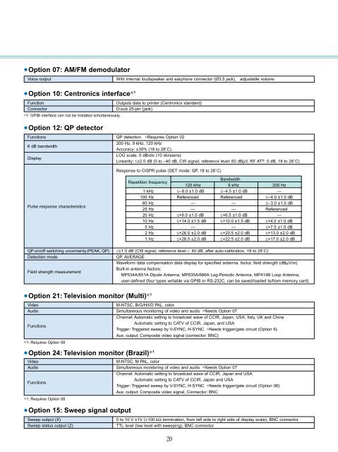
•Option 07: AM/FM demodulator<br />
Voice output<br />
With internal loudspeaker and earphone connector (Ø3.5 jack), adjustable volume<br />
•Option 10: Centronics interface∗ 1<br />
Function<br />
Connector<br />
∗1: GPIB interface can not be installed simultaneously.<br />
•Option 12: QP detector<br />
Outputs data to printer (Centronics standard)<br />
D-sub 25-pin (jack)<br />
Functions QP detection ∗Requires Option 02<br />
6 dB bandwidth<br />
200 Hz, 9 kHz, 120 kHz<br />
Accuracy: ±30% (18 to 28˚C)<br />
Display<br />
LOG scale, 5 dB/div (10 divisions)<br />
Linearity: ≤±2.0 dB (0 to –40 dB, CW signal, reference level: 60 dBµV, RF ATT: 0 dB, 18 to 28˚C)<br />
Response to CISPR pulse (DET mode: QP, 18 to 28˚C)<br />
Pulse response characteristics<br />
QP on/off switching uncertainty (PEAK, QP)<br />
Detection mode<br />
Field strength measurement<br />
Repetition frequency<br />
Bandwidth<br />
120 kHz 9 kHz 200 Hz<br />
1 kHz ≤–8.0 ±1.0 dB ≤–4.5 ±1.0 dB —<br />
100 Hz Referenced Referenced ≤–4.0 ±1.0 dB<br />
60 Hz — — ≤–3.0 ±1.0 dB<br />
25 Hz — — Referenced<br />
20 Hz ≤+9.0 ±1.0 dB ≤+6.5 ±1.0 dB —<br />
10 Hz ≤+14.0 ±1.5 dB ≤+10.0 ±1.5 dB ≤+4.0 ±1.0 dB<br />
5 Hz — — ≤+7.5 ±1.5 dB<br />
2 Hz ≤+26.0 ±2.0 dB ≤+20.5 ±2.0 dB ≤+13.0 ±2.0 dB<br />
1 Hz ≤+28.5 ±2.0 dB ≤+22.5 ±2.0 dB ≤+17.0 ±2.0 dB<br />
≤±1.0 dB (CW signal, reference level – 40 dB, after auto-calibration, 18 to 28˚C)<br />
QP, AVERAGE<br />
Waveform data compensation data display for specified antenna factor, field strength (dBµV/m)<br />
Built-in antenna factors:<br />
MP534A/651A Dipole Antenna, MP635A/666A Log-Periodic Antenna, MP414B Loop Antenna,<br />
user-defined (four types writable via GPIB or RS-232C, can be saved/loaded to/from memory card)<br />
•Option 21: Television monitor (Multi)∗ 1<br />
Video<br />
M-NTSC, B/G/H/I/D PAL, color<br />
Audio Simultaneous monitoring of video and audio ∗Needs Option 07<br />
Channel: Automatic setting to broadcast wave of CCIR, Japan, USA, Italy, UK and China<br />
Automatic setting to CATV of CCIR, Japan, and USA<br />
Functions<br />
Trigger: Triggered sweep by V-SYNC, H-SYNC ∗Needs trigger/gate circuit (Option 6)<br />
Aux. output: Composite video signal (connector: BNC)<br />
∗1: Requires Option 08<br />
•Option 24: Television monitor (Brazil)∗ 1<br />
Video<br />
M-NTSC, M PAL, color<br />
Audio Simultaneous monitoring of video and audio ∗Needs Option 07<br />
Functions<br />
∗1: Requires Option 08<br />
•Option 15: Sweep signal output<br />
Sweep output (X)<br />
Sweep status output (Z)<br />
Channel: Automatic setting to broadcast wave of CCIR, Japan and USA<br />
Automatic setting to CATV of CCIR, Japan and USA<br />
Trigger: Triggered sweep by V-SYNC, H-SYNC ∗Needs trigger/gate circuit (Option 06)<br />
Aux. output: Composite video signal, Connector: BNC<br />
0 to 10 V ±1V (≥100 kΩ termination, from left side to right side of display scale), BNC connector<br />
TTL level (low level with sweeping), BNC connector<br />
20