Anritsu MS2663C Spectrum Analyzer Data Sheet - Mr Test Equipment
Anritsu MS2663C Spectrum Analyzer Data Sheet - Mr Test Equipment
Anritsu MS2663C Spectrum Analyzer Data Sheet - Mr Test Equipment

Create successful ePaper yourself
Turn your PDF publications into a flip-book with our unique Google optimized e-Paper software.
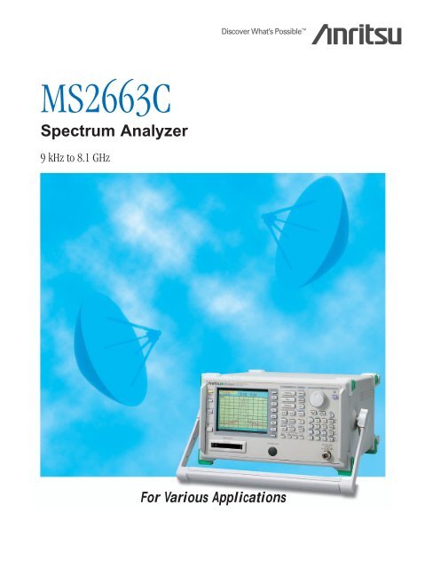
<strong>MS2663C</strong><br />
<strong>Spectrum</strong> <strong>Analyzer</strong><br />
9 kHz to 8.1 GHz<br />
For Various Applications
Portable at Only 13.5 kg<br />
The <strong>MS2663C</strong> covers a frequency range of 9 kHz to<br />
8.1 GHz. This allows measurement of spurious<br />
frequencies of up to three times greater than the<br />
frequency bands used worldwide for mobile<br />
communications.<br />
The <strong>MS2663C</strong> has superior basic performance such<br />
as high C/N ratio, low distortion, and high<br />
frequency/level accuracies and is easy to operate.<br />
In addition, a Gaussian filter is used as the resolution<br />
bandwidth filter. The large selection of options means<br />
a wide range of applications can be handled at<br />
reasonable cost.<br />
Compact and lightweight<br />
(13.5 kg in standard configuration)<br />
•Easy portability for installation and maintenance<br />
High C/N and superior distortion<br />
characteristics<br />
•Measurement speed improved by using 100 dB log<br />
dynamic range<br />
Easy-to-use, simple operation<br />
•Built-in “Measure” function for evaluation of radio<br />
equipment (Frequency counter, C/N, channel power,<br />
adjacent channel power, occupied frequency<br />
bandwidth, burst average power and template<br />
pass/fail function)<br />
•User-defined function<br />
•Zone marker/zone sweep<br />
•Two-screen display<br />
•FM demodulation waveform display
•Memory card interface (for saving/recalling trace data and<br />
parameter and for saving screen image in bitmap format)<br />
Options support wide range of applications<br />
•High stability crystal oscillator<br />
•Narrow resolution bandwidth<br />
•High-speed time domain sweep<br />
•Trigger/gate circuit<br />
•AM/FM demodulator<br />
•Pre-amplifier<br />
•Centronics interface (can not be installed GPIB simultaneously)<br />
•QP detector<br />
•Television monitor<br />
•Tracking generator<br />
Easy to set up automatic measurements<br />
•Controller function built-in (PTA)<br />
•Built-in RS-232C and GPIB (standard)<br />
•Various application software
Compact, Lightweight, and Powerful<br />
•Small and weighing only 13.5 kg<br />
The <strong>MS2663C</strong> is compact and lightweight,<br />
measuring 320 (W) x 177 (H) x 351 (D) mm<br />
and weighing only 13.5 kg.In addition to<br />
benchtop use, this can be carried easily for<br />
field use, making it the ideal choice for<br />
manufacturing and maintenance of radio<br />
equipment.<br />
•Synthesized local oscillator<br />
The synthesized local oscillator design<br />
permits stable measurement without<br />
disturbance due to frequency drift of the<br />
spectrum analyzer itself. The level stabilizes<br />
in 30 minutes after power-on, making this<br />
unit especially suitable for on-site maintenance<br />
and adjustment where work must be<br />
completed quickly.<br />
•Counter with 1 Hz resolution<br />
A full complement of frequency counter<br />
functions are provided. Resolution is a high<br />
±1 Hz even at full span, and high-speed<br />
frequency measurements can be performed.<br />
The high sensitivity compared with ordinary<br />
counters makes it easy to select one signal<br />
from many and to determine its frequency.<br />
•High C/N ratio<br />
Excellent noise sideband characteristics are<br />
required for analysis of weak signals<br />
adjacent to strong signals. The <strong>MS2663C</strong><br />
has low noise sidebands of below –100 dBc/<br />
Hz (10 kHz offset), making it suitable for<br />
measurement of adjacent channel power of<br />
both analog and digital radio communication<br />
equipment.<br />
Noise sidebands measurement (10 kHz offset)<br />
Frequency measurement (1 Hz resolution)<br />
4
•Superior distortion characteristics<br />
The <strong>MS2663C</strong> boasts extremely low<br />
harmonic distortion levels, including a second<br />
harmonic distortion of –75 dBc ∗1 and a twosignal<br />
third order intermodulation distortion<br />
of –80 dBc ∗2 making it suitable for measuring<br />
harmonic components and for evaluating the<br />
non-linearity of high-power amplifiers.<br />
∗ 1 200 MHz to 1.3 GHz, mixer input: –30 dBm<br />
∗ 2 100 MHz to 8.1 GHz, frequency difference between signals:<br />
≥50 kHz, mixer input: –30 dBm<br />
•100 dB display dynamic range<br />
In measurements requiring a wide dynamic<br />
range such as adjacent channel power<br />
measurements, <strong>MS2663C</strong> can displayed<br />
more than 80 dB on a single screen.<br />
•Excellent cost performance<br />
The superior basic performance, including<br />
noise sideband, average noise level, and<br />
spurious response, provides excellent cost<br />
performance.<br />
Noise sideband ∗1<br />
Average noise level ∗2<br />
Maximum distortion<br />
dynamic range<br />
≤–100 dBc/Hz<br />
≤–115 dBm<br />
2nd harmonic:<br />
>80 dB (200 to 500 MHz)<br />
3rd intermodulation distortion:<br />
>83.3 dB (100 to 1000 MHz)<br />
∗ 1 1 GHz, 10 kHz offset<br />
∗ 2 1 MHz to 1 GHz, RBW: 1kHz, VBW: 1 Hz, RF ATT: 0 dB<br />
2nd harmonic distortion<br />
Two signal 3rd intermodulation distortion<br />
Two-signal third order intermodulation measurement<br />
•Highly-accurate measurement<br />
Auto-calibration ensures an overall level<br />
accuracy of within ±1.3 dB (100 kHz to 3.1<br />
GHz). A span accuracy of 2.5% and 501<br />
sampling points ensure accurate occupied<br />
frequency bandwidth and adjacent channel<br />
power measurements.<br />
Average noise<br />
level (dBm)<br />
Distortion<br />
relative value<br />
(dB)<br />
–20 100 MHz~3 GHz<br />
–30<br />
–40<br />
–50<br />
–60<br />
–70<br />
–80<br />
–90<br />
800 MHz~1 GHz<br />
200 MHz~1.5 GHz<br />
Average noise level<br />
–60 –40 –20 0 +20<br />
Mixer input level (=input level – RF ATT)<br />
Distortion characteristics<br />
Occupied bandwidth measurement<br />
5
Convenient Easy-to-Use Functions<br />
•Simple operation<br />
Users require ease of operation in a wide<br />
variety of contexts. For greater ease, in<br />
addition to simplifying the panel keys and<br />
key layout, also menu page configuration is<br />
well organized and “page-learning” as well<br />
as “user-defined” functions have been added<br />
to minimize the steps required for a given<br />
procedure.<br />
•Bright color screen<br />
A 5.5” bright color TFT LCD is used to<br />
display scales, measured waveform data,<br />
settings and other information in different<br />
easy-to-read colors. Each color can be<br />
changed if required. When the soft key<br />
display is turned off, the scale area enlarges<br />
to 80 (H) x 180 (W) mm, comparable to an<br />
8” CRT.<br />
•Radio equipment evaluation<br />
functions (“measure” functions)<br />
A full range of functions including<br />
measurement of power levels, frequencies,<br />
adjacent channel power, and mask and time<br />
template measurements are provided for<br />
performance evaluation of radio equipment.<br />
Key operation is simple and high-speed<br />
calculations make the measurement fast<br />
and efficient.<br />
Channel power measurement<br />
Burst average power measurement<br />
Adjacent channel power measurement<br />
Mask measurement<br />
Time template measurement<br />
6
•FM-demodulated waveform<br />
display function<br />
This function displays FM-demodulated<br />
waveforms with an accuracy of 5% over the<br />
range ±10 kHz to ±1 MHz. When used with<br />
high-speed time domain sweep (Option 04)<br />
and trigger/gate circuit (Option 06),<br />
frequency deviation of the modulated signal,<br />
and frequency switching times of radio<br />
equipment and VCOs, can be measured.<br />
•Zone markers and multimarkers<br />
Zone markers can be set automatically at<br />
the peak signal within a given marker range,<br />
enabling quick measurement. By using the<br />
multimarker function, automatic<br />
measurements can be performed at up to<br />
ten marker points, and the results displayed<br />
in a table. Multimarkers have functions for<br />
harmonic measurements, highest 10 points<br />
and manual setting.<br />
<strong>Spectrum</strong> and FM-demodulation waveform<br />
Multi marker (highest 10 points)<br />
Multi marker (harmonics measurement)<br />
7
•Zone sweep and multi-zone<br />
sweep functions<br />
Sweeps can be limited to zones defined by<br />
zone markers reducing sweep time. This<br />
zone sweep function can be combined with<br />
“measure” functions such as “noise<br />
measure” which can direct readout the total<br />
noise power within the zone, and reduces<br />
measurement time greatly. The multi-zone<br />
sweep function enables up to ten zones to<br />
be swept.<br />
Two traces with different frequencies<br />
Multi-zone sweep<br />
•Multi-screen display<br />
The Trace-A and Trace-B waveforms are<br />
superimposed on the same screen, and two<br />
spectra with different frequencies are<br />
displayed simultaneously. In addition, it is<br />
possible to simultaneously display spectrum<br />
and time domain screens for the same<br />
signal. The multi-screen display permits<br />
efficient signal level adjustment and<br />
harmonic distortion measurement, too.<br />
Furthermore, in addition to being able to<br />
display amplitude in the time domain, it is<br />
also possible to display the FM<br />
demodulation waveform.<br />
<strong>Spectrum</strong> and time domain measurement<br />
8
•User-defined functions<br />
Measurement programs downloaded to the<br />
spectrum analyzers from a personal<br />
computer or memory card can be executed<br />
by defining menu keys. The measurement<br />
program is executed simply by pressing the<br />
predefined key, with no further operation.<br />
Other panel and function keys can also be<br />
predefined in the same way.<br />
•Screen image bitmap saved to<br />
memory card<br />
Instead of printing a hard copy of the<br />
screen, it is also possible to save the screen<br />
image to a memory card in bitmap format.<br />
Editing the saved bitmap data using a PC,<br />
makes report writing easy.<br />
Measurement programs<br />
definition (downloaded<br />
from personal computer)<br />
Panel and function keys<br />
definition<br />
When the mode to save the<br />
screen image in bitmap<br />
format to the memory card<br />
is selected as a copy<br />
method at the hard copy<br />
function, just one press of<br />
the copy key saves the<br />
screen image as a bitmap<br />
format to the memory card.<br />
And the file number of each<br />
saved file is incremented<br />
automatically.<br />
User-defined menu<br />
The screen image data can<br />
also be saved to the<br />
memory card using the<br />
save function. In this case,<br />
the file number of the<br />
saved file can be specified.<br />
9
Full Range of Options<br />
Full lineup of options to select required<br />
performance and functions with minimum<br />
capital investment.<br />
•To boost basic performance<br />
High-stability reference oscillator<br />
(Option 01)<br />
Adding the optional reference oscillator with<br />
a stability of 2 x 10 –8 /day and 1 x 10 –7 /year<br />
increases the accuracy of frequency<br />
measurements even further.<br />
Narrow resolution bandwidth (Option 02)<br />
Adding the option for a resolution bandwidth<br />
of 30 Hz, 100 Hz and 300 Hz greatly<br />
improves frequency resolution.<br />
Pre-amplifier (Option 08)<br />
The Pre-amplifier improves the sensitivity<br />
(noise figure) of the spectrum analyzer, and<br />
is best used when studying interference signals<br />
and other low-power signals. It covers<br />
a frequency range from 100 kHz to 3 GHz.<br />
•For testing digital mobile<br />
communication equipment<br />
High-speed time domain sweep<br />
(Option 04)<br />
<strong>Test</strong>ing of TDMA-type radio equipment<br />
includes time domain (zero-span)<br />
measurements of antenna power, transient<br />
response characteristics of burst<br />
transmissions, transmission timing, and<br />
other quantities. The high-speed time<br />
domain sweep option boosts a sweep time<br />
to 12.5 µs and resolution to 0.025 µs. This<br />
option must be used with the trigger/gate<br />
circuit (Option 06).<br />
High-speed time-domain measurement (TS=12.5 µ s)<br />
Low-power signal measurement using RF pre-amplifier<br />
10
Trigger/gate circuit (Option 06)<br />
Burst signal and TV signals etc. can be<br />
stably measured using the trigger function<br />
in time-domain measurements. One of the<br />
external, video, wide IF video, line or TV is<br />
selectable. This makes a variety of TDMA<br />
radio equipment tests possible, including<br />
template comparison using pre-trigger and<br />
post-trigger delay functions, and gate<br />
spectrum analysis using the gate sweep<br />
function. Previously, the trigger output from<br />
an external detector was required in gate<br />
spectrum analysis. However, this option for<br />
the <strong>MS2663C</strong> has a 20 MHz wide IF video<br />
trigger function, eliminating the need for<br />
trigger output from an external detector.<br />
•For CATV maintenance<br />
50 Ω/75 Ω impedance transformer<br />
Converts RF input impedance to 75 Ω<br />
AM/FM demodulator (Option 07)<br />
Demodulates AM/FM signals, enabling<br />
audio monitoring using internal speaker or<br />
earphones. This is useful for distinguishing<br />
between noise and signals.<br />
Television monitor (Option 21/24)<br />
This option displays TV (NTSC or PAL)<br />
signals (requires Option 08). When used<br />
with the AM/FM demodulator (Option 07),<br />
audio signals can be monitored simultaneously.<br />
With addition of high-speed time<br />
domain sweep (Option 04) and the<br />
trigger/gate circuit (Option 06), measurement<br />
of CATV parameters such as carrier<br />
level/frequency, C/N, modulation, distortion,<br />
hum and low-frequency interference etc.<br />
becomes possible.<br />
Wide IF video trigger function<br />
NTSC TV signal waveform<br />
•EMI measurement<br />
EMI of electronic devices can be measured<br />
using the QP detector (Option 12).<br />
Wide IF video trigger and gate functions<br />
11
Easy-to-Use Key Layout<br />
1 Function keys F1 to F6<br />
Select on-screen menu items<br />
Menu on/off keys turn menus on and off, and [more] key turns menu<br />
pages.<br />
2 Save/recall<br />
Saves and recalls measurement settings and measured waveforms<br />
<strong>Data</strong> can be saved either to internal memory or to a memory card.<br />
(Using internal memory, up to 12 data sets can be saved.)<br />
3 Main functions<br />
Set frequency, span, amplitude and other parameters<br />
4 Markers<br />
Normal markers, multimarkers (maximum 10 numbers), zone markers<br />
and zone sweeping are provided.<br />
5 Entry keys<br />
Input numeric values, units, and alphabetic characters<br />
6 User keys<br />
Register any panel and menu key functions, as well as application<br />
software functions to user keys.<br />
7 User define key<br />
Define functions of user-defined keys. Up to 3-pages can be predefined.<br />
8 Measure key<br />
Executes various operations based on waveform data<br />
High-speed measurements and computations are performed without<br />
the need for an external computer.<br />
9 Calibration<br />
The built-in high-precision calibration signal source provides accurate<br />
measurements.<br />
10 Trigger/gate, TV monitor<br />
The trigger can be set in the time domain mode, and analog TV video<br />
signals can be monitored.<br />
11 Coupled-function keys<br />
Set parameters other than those set using main function keys<br />
Normally set “Auto” for optimum values.<br />
12 Display<br />
Can be switched between frequency and time domains, and has twoscreen<br />
display modes<br />
13 Memory card slots<br />
Support memory cards up to 2 Mbytes<br />
Two type-1 memory cards conforming to PCMCIA ver. 2.0 standards can<br />
be used simultaneously.<br />
14 RF connector<br />
For input of signals at levels up to +30 dBm (maximum DC input: ±0 V)<br />
13<br />
12
1 2 3 4 5<br />
6<br />
7<br />
8<br />
9<br />
14<br />
12<br />
11<br />
10<br />
13
Configuring Automated Measurement System<br />
•RS-232C interface (standard)<br />
The RS-232C interface can be used to output hard copy data to<br />
a printer or plotter and for remote control of the analyzer.<br />
A notebook computer can be used for automated control and<br />
data collection in the field. In addition, a modem can be used for<br />
easy remote operation.<br />
•GPIB interface (standard)<br />
In addition to remote control, the GPIB interface can also be<br />
used to output data to a printer/plotter. (GPIB and Option 10<br />
can not be installed simultaneously.)<br />
•Centronics interface (Option 10)<br />
This Centronics interface is installed to output data to a printer.<br />
(GPIB and Option 10 can not be installed simultaneously.)<br />
•Memory card interface (standard)<br />
Memory cards are used to save and recall measurement<br />
settings and waveform data, as well as to upload and download<br />
PTA programs. Cards up to 2 Mbytes are supported (PCMCIA<br />
ver. 2.0, type-I, 2-slots).<br />
RS-232C, GPIB<br />
or Centronics<br />
<strong>MS2663C</strong><br />
Printer/plotter<br />
RS-232C<br />
Centronics<br />
or GPIB<br />
Personal computer<br />
<strong>MS2663C</strong><br />
Printer/plotter<br />
RS-232C Line RS-232C<br />
Personal computer<br />
Modem<br />
Modem<br />
<strong>MS2663C</strong><br />
GPIB<br />
RS-232C<br />
Personal computer<br />
<strong>MS2663C</strong><br />
Printer/plotter<br />
14
•Automated measurement without external controller<br />
The built-in microcomputer (PTA) functions which utilize the spectrum<br />
analyzer as a controller, make an external controller unnecessary. An<br />
automated measurement system including control of other instruments<br />
is easily configured. The two methods for loading programs are shown<br />
below.<br />
Programs written on a computer are saved to a memory card.<br />
The memory card is inserted into a memory card slot in the<br />
spectrum analyzer and the programs are loaded.<br />
Personal computer<br />
Memory card<br />
RS-232C, or GPIB<br />
<strong>MS2663C</strong><br />
Personal computer<br />
Programs written on a computer are transferred to the spectrum<br />
analyzer via the RS-232C or GPIB interface.<br />
•Application software<br />
The following items can be measured automatically using a combination of application<br />
software, peripheral equipment and options.<br />
MX260002A CDMA Cellular System Measurement Software<br />
Channel power, occupied frequency bandwidth, adjacent channel power, time<br />
response for open-loop power control, spurious<br />
MX260003A PDC Measurement Software (for base station)<br />
Channel power, frequency, occupied frequency bandwidth, adjacent channel power,<br />
spurious<br />
MX260004A GSM Measurement Software<br />
Power, time response, adjacent channel power, spurious, intermodulation<br />
characteristics<br />
MX261001A Low-Power <strong>Data</strong> Communication System Measurement Software<br />
conforming to issue of Direct Spread <strong>Spectrum</strong> System<br />
MX261002A Low-Power <strong>Data</strong> Communication System Measurement Software<br />
conforming to issue of Frequency Hopping System<br />
Frequency, power, occupied frequency bandwidth, adjacent channel power, spurious<br />
MX262001A CATV Measurement Software<br />
Video power, C/N, frequency, cross modulation, CTB, modulation factor, hum<br />
MX264001A EMI Measurement Software<br />
Radiated emission, conducted emission<br />
15
Specifications<br />
Except where noted otherwise, specified values were obtained after warming up the equipment for 30 minutes at a constant ambient<br />
temperature and then performing calibration. The typical values are given for reference, and are not guaranteed.<br />
Frequency<br />
Amplitude<br />
Frequency range<br />
9 kHz to 8.1 GHz<br />
Frequency band<br />
Band 0 (0 to 3.2 GHz), band 1– (2.92 to 6.5 GHz), band 1+ (6.4 to 8.1 GHz)<br />
Pre-selector range 2.92 to 8.1 GHz (band 1–, 1+)<br />
Display frequency<br />
±(display frequency x reference frequency accuracy + span x span accuracy + 100 Hz)<br />
accuracy<br />
∗Span: ≥10 kHz, after calibration<br />
Marker frequency display<br />
Normal: Same as display frequency accuracy, Delta: Same as frequency span accuracy<br />
accuracy<br />
Resolution: 1 Hz, 10 Hz, 100 Hz, 1 kHz<br />
Frequency counter<br />
Accuracy: Display frequency x reference frequency accuracy ±1 LSD (at S/N: ≥20 dB)<br />
Setting range: 0 Hz, 1 kHz to 8.2 GHz<br />
Frequency span<br />
Accuracy: ±2.5% (span: ≥10 kHz), ±5% (span:
Amplitude<br />
Sweep<br />
Functions<br />
Scale (10 div)<br />
Log scale: 10, 5, 2, 1 dB/div<br />
Linear scale: 10, 5, 2, 1%/div<br />
Linearity (after calibration)<br />
Waveform display<br />
Log scale: ±0.4 dB (0 to –20 dB, RBW: ≤1 MHz), ±1.0 dB (0 to –70 dB, RBW: ≤100 kHz),<br />
±1.5 dB (0 to –85 dB, RBW: ≤3 kHz), ±2.5 dB (0 to –90 dB, RBW: ≤3 kHz)<br />
Linear scale: ±4% (compared to reference level)<br />
Marker level resolution<br />
Log scale: 0.01 dB, Linear scale: 0.02% of reference level<br />
2nd harmonic distortion:<br />
≤–60 dBc (10 to 200 MHz, band 0, mixer input: –30 dBm), ≤–75 dBc (0.2 to 1.3 GHz, band 0, mixer input:<br />
–30 dBm), ≤–70 dBc (1.3 to 1.55 GHz, band 0, mixer input: –30 dBm), ≤–80 dBc (0.8 to 1 GHz, band 0,<br />
mixer input: –30 dBm), ≤–100 dBc (1.46 to 4.05 GHz, band 1, mixer input: –20 dBm)<br />
Spurious response<br />
Two signals 3rd order intermodulation distortion:<br />
≤–70 dBc (10 to 100 MHz), ≤–80 dBc (0.1 to 8.1 GHz)<br />
∗Frequency difference of two signals: ≥50 kHz, mixer input: –30 dBm<br />
Image response: ≤–70 dBc, Multiple response: ≤–70 dBc (band 1)<br />
1 dB gain compression ≥–5 dBm (≥100 MHz, at mixer input level)<br />
1 dB gain compression level to average noise level:<br />
>110 dB (0.1 to 1 GHz, band 0), >110 dB –1.5f [GHz] dB (1 to 3.1 GHz, band 0),<br />
>110 dB –0.5f [GHz] dB (2.92 to 8.1 GHz, band 1)<br />
Distortion characteristics (RBW: 1 kHz)<br />
2nd harmonic: >72.5 dB (10 to 200 MHz), >80 dB (200 to 500 MHz), >80 –0.75f [GHz] dB (0.5 to 1.3 GHz),<br />
Maximum dynamic range<br />
>82.5 –0.75f [GHz] dB (0.8 to 1 GHz), >77.5 –0.75f [GHz] dB (1.3 to 1.55 GHz, band 0),<br />
>97.5 –0.25f [GHz] dB (1.46 to 4.05 GHz, band 1)<br />
3rd order intermodulation : >80 dB (10 to 100 MHz), >83.3 dB (0.1 to 1 GHz),<br />
>83.3 –f [GHz] dB (1 to 3.1 GHz, band 0),<br />
>83.3 –(1/3)f [GHz] dB (2.92 to 8.1 GHz, band 1)<br />
Setting range: 20 ms to 1000 s (manually settable, or automatically settable according to span, RBW, and VBW)<br />
Sweep time<br />
Accuracy: ±15% (20 ms to 100 s), ±45% (110 to 1000 s), ±1% (time domain sweep: digital zero span mode)<br />
Sweep mode<br />
Continuous, single<br />
Time domain sweep mode Analog zero span, digital zero span<br />
Zone sweep<br />
Sweeps only in frequency range indicated by zone marker<br />
Tracking sweep<br />
Sweeps while tracing peak points within zone marker (zone sweep also possible)<br />
Number of data points 501<br />
NORMAL: Simultaneously displays max. and min. points between sample points<br />
POS PEAK: Displays max. point between sample points<br />
Detection mode<br />
NEG PEAK: Displays min. point between sample points<br />
SAMPLE: Displays momentary value at sample points<br />
Detection mode switching uncertainty: ±0.5 dB (at reference level)<br />
Color TFT-LCD, Size: 5.5”, Number of colors: 17 (RGB, each 64-scale settable), Intensity<br />
Display<br />
adjustment: 5 steps settable<br />
Trace A: Displays frequency spectrum<br />
Trace B: Displays frequency spectrum<br />
Trace Time: Displays time domain waveform at center frequency<br />
Trace A/B: Displays Trace A and Trace B simultaneously. Simultaneous sweep of same frequency,alternate<br />
alternate sweep of independent frequencies<br />
Display functions<br />
Trace A/BG: Displays frequency region to be observed (background) and object band (foreground) selected<br />
from background with zone marker simultaneously, alternate sweep<br />
Trace A/Time: Displays frequency spectrum, and time domain waveform at center frequency simultaneously,<br />
alternate sweep<br />
Trace move/calculation: A B, B A, A B, A + B A, A – B A, A – B + DL A<br />
Storage functions<br />
NORMAL, VIEW, MAX HOLD, MIN HOLD, AVERAGE, CUMULATIVE, OVER WRITE<br />
Demodulation range: 2, 5, 10, 20, 50, 100, 200 kHz/div<br />
Marker display<br />
Accuracy: ±5% of full scale (referenced to center frequency, DC-coupled. RBW: 3 MHz, VBW: 1 Hz, CW)<br />
FM demodulation<br />
Demodulation frequency range: DC (50 Hz at AC-coupled) to 100 kHz (range: ≤20 kHz/div, VBW: off, at 3 dB<br />
waveform display function<br />
bandwidth)<br />
DC (50 Hz at AC-coupled) to 500 kHz (range: ≥50 kHz/div, VBW: off, at 3 dB<br />
bandwidth)<br />
∗RBW: ≥1 kHz usable<br />
Input connector<br />
N-J, 50 Ω<br />
IF OUTPUT: 10.69 MHz, BNC connector<br />
VIDEO OUTPUT (Y): 0 to 0.5 V ±0.1 V (100 MHz, from lower edge to upper edge at 10 dB/div or 10%/div, 75 Ω<br />
Auxiliary signal input<br />
terminated), BNC connector<br />
and output<br />
COMPOSITE OUTPUT: For NTSC, 1 Vp-p (75 Ω terminated), BNC connector<br />
EXT REF INPUT: 10 MHz ±10 Hz, ≥0 dBm (50 Ω terminated), BNC connector<br />
17
Functions<br />
Others<br />
Signal search AUTO TUNE, PEAK CF, PEAK REF, SCROLL<br />
Zone marker<br />
NORMAL, DELTA<br />
Marker MARKER CF, MARKER REF, MARKER CF STEP SIZE, ∆MARKER SPAN, ZONE SPAN<br />
Peak search<br />
PEAK, NEXT PEAK, NEXT RIGHT PEAK, NEXT LEFT PEAK, MIN DIP, NEXT DIP<br />
Multimarker<br />
Number of markers: 10 max. (HIGHEST 10, HARMONICS, MANUAL SET)<br />
Noise power (dBm/Hz, dBm/ch), C/N (dBc/Hz, dBc/ch), occupied bandwidth (power N% method, X-dB down<br />
method), adjacent channel power (REF: total power/reference level/in-band level method, channel designate<br />
Measure<br />
display: 2 channels x 2 graphic display), average power of burst signal (average power in designated time range<br />
of time domain waveform), channel power (dBm, dBm/Hz), template comparison (upper/lower limits x each 2,<br />
time domain), MASK (upper/lower x each 2, frequency domain)<br />
Save/recall<br />
Save and recall setting conditions and waveform data to internal memory (max.12) or memory card<br />
Printer (HP dotmatrix, EPSON dotmatrix compatible models):<br />
Hard copy<br />
Display data can be hard-copied via RS-232C, GPIB and Centronics (Option 10) interface<br />
Plotter (HP-GL, GP-GL compatible models):<br />
Display data can be output via RS-232C, and GPIB interface<br />
Language: PTL (interpreter based on BASIC)<br />
Programming: Using external computer<br />
PTA<br />
Program memory: Memory card, upload/download to/from external computer<br />
Programming capacity: 192 KB<br />
<strong>Data</strong> processing: Directly accesses measurement data according to system variables, system subroutines, and<br />
system functions<br />
RS-232C<br />
Outputs data to printer and plotter. Control from external computer (excluding power switch)<br />
Meets IEEE488.2. Controlled by external computer (excluding power switch). Or controls external equipment<br />
GPIB<br />
with PTA<br />
Interface function: SH1, AH1, T6, L4, SR1, RL1, PP0, DC1, DT1, C1, C2, C3, C4, C28<br />
Automatic correction of insertion loss of MA1621A Impedance Transformer<br />
Correction accuracy (RF ATT: ≥10 dB):<br />
±2.5 dB (9 to 100 kHz), ±1.5 dB (100 kHz to 2 GHz), ±2.0 dB (2 to 3 GHz, typical)<br />
Correction<br />
Antenna correction coefficients:<br />
Correct display and measurement of field strengths (dBµV/m) for specified antennas<br />
Internal antenna correction coefficients (MP534A/651A Dipole Antenna, MP635A/666A Log-Periodic Antenna,<br />
MP414B Loop Antenna, and four antennas user-defined; write via GPIB or RS-232C, save/load to/from<br />
memory card)<br />
Functions: Saving/recalling measurement parameters/waveform data, uploading/downloading PTA programs;<br />
Memory card interface<br />
Applicable cards: SRAM, EPROM, Flash EPROM ∗Only SRAM writable; Card capacity: 2 MB max.<br />
Connector: Meets the JEIDA Ver. 4/4.1, PCMCIA Rel. 2.0; 2 slots<br />
EN61326: 1997/A2: 2001 (Class A)<br />
EMC EN61000-3-2: 2000 (Class A)<br />
EN61326: 1997/A2: 2001 (Annex A)<br />
LVD EN61010-1: 2001 (Pollution Degree 2)<br />
Vibration<br />
Meets the MIL-STD-810D<br />
Power (operating range)<br />
85 to 132/170 to 250 Vac (automatic voltage switching), 47.5 to 63 Hz, 380 to 420 Hz<br />
(85 to 132 V only), ≤330 VA<br />
Dimensions and mass 320 (W) x 177 (H) x 351 (D) mm, ≤13.5 kg (without option)<br />
Ambient temperature<br />
0 to +50˚C (operate), –40 to +75˚C (storage)<br />
•Option 01: Reference crystal oscillator<br />
Frequency<br />
10 MHz<br />
Aging rate ≤1 x 10 –7 /year, ≤2 x 10 –8 /day (after power on, with reference to frequency after 24 h)<br />
Temperature characteristics<br />
±5 x 10 –8 (0 to 50˚C, with reference to 25˚C)<br />
Buffer output<br />
10 MHz, >2 Vp-p (200 Ω termination), BNC connector<br />
•Option 02: Narrow resolution bandwidth<br />
Resolution bandwidth (3 dB)<br />
30 Hz, 100 Hz, 300 Hz<br />
Resolution bandwidth switching uncertainty ±0.4 dB (RBW 3 kHz referenced)<br />
Resolution bandwidth accuracy<br />
±20% (100, 300 Hz)<br />
Selectivity (60 dB:3 dB)<br />
≤15:1 (RBW: 100, 300 Hz), ≤20:1 (RBW: 30 Hz)<br />
18
•Option 04: High-speed time domain sweep<br />
Sweep time<br />
12.5 µs, 25 µs, 50 µs, 100 to 900 µs (one most significant digit settable),<br />
1.0 to 19 ms (two upper significant digits settable)<br />
Accuracy ±1%<br />
Marker level resolution<br />
0.1 dB (log scale), 0.2% (linear scale, relative to reference level)<br />
•Option 06: Trigger/gate circuit<br />
Trigger switch<br />
Trigger source<br />
Trigger delay<br />
Gate sweep<br />
EXT<br />
VIDEO<br />
WIDE IF VIDEO<br />
LINE<br />
TV<br />
FREERUN, TRIGGERED<br />
Trigger level: ±10 V (resolution: 0.1 V), TTL level<br />
Trigger slope: Rise, fall<br />
Connector: BNC<br />
Log scale: –100 to 0 dB (resolution: 1 dB)<br />
Trigger slope: Rise, fall<br />
Trigger level: High, middle, or low selectable<br />
Bandwidth: ≥20 MHz<br />
Trigger slope: Rise, fall<br />
Frequency: 47.5 to 63 Hz (line lock)<br />
Method: M-NTSC, B/G/H PAL<br />
Sync: V-SYNC, H-SYNC<br />
Sync line (NTSC)<br />
H-SYNC (ODD): 7 to 262 line, H-SYNC (EVEN): 1 to 263 line<br />
Sync line (PAL)<br />
H-SYNC (ODD): 1 to 312 line, H-SYNC (EVEN): 317 to 625 line<br />
∗Option 16 required<br />
Pre-trigger (displays waveform from previous max. 1 screen at trigger occurrence point)<br />
Range: –time span to 0 s, Resolution: time span/500<br />
Post trigger (displays waveform from after max. 65.5 ms at trigger occurrence point)<br />
Range: 0 to 65.5 ms, Resolution: 1 µs<br />
In frequency domain, displays spectrum of input signal in specified gate interval<br />
Gate delay: 0 to 65.5 ms (from trigger point, resolution: 1 µs)<br />
Gate width: 2 µs to 65.5 ms (from gate delay, resolution: 1 µs)<br />
•Option 08: Pre-amplifier∗ 1, ∗ 3<br />
Frequency range<br />
100 kHz to 3 GHz<br />
Noise figure<br />
≤8 dB (typical, 1 GHz) ∗RBW: 1 kHz, VBW: 1 Hz, RF ATT: 0 dB<br />
Setting range<br />
Log scale: –120 to +10 dBm, or equivalent level<br />
Linear scale: 22.4 µV to 707 mV<br />
Reference level accuracy: ±0.5 dB (–69.9 to –20 dBm), ±0.75 dB (–89.9 to –70 dBm, –19.9 to +10 dBm)<br />
Reference level<br />
∗After calibration, referenced to 100 MHz, span: 1 MHz (RF ATT, RBW, VBW and sweep time set to AUTO)<br />
RBW switching uncertainty: ±0.5 dB ∗After calibration, referenced to RBW: 3 kHz<br />
RF ATT switching uncertainty: ±0.5 dB (0 to 50 dB), ±1.0 dB (0 to 70 dB)<br />
∗After calibration, referenced to 100 MHz, RF ATT: 10 dB<br />
Frequency response<br />
±2.0 dB (100 kHz to 3 GHz, referenced to 100 MHz, RF ATT: 10 to 50 dB)<br />
Log scale (after calibration): ±0.5 dB (0 to –20 dB), ±1.0 dB (0 to –60 dB), ±1.5 dB (0 to –75 dB)<br />
Linearity of waveform display<br />
Linear scale (after calibration): ±5% (according to reference level)<br />
Two signals 3rd order intermodulation distortion: ≤–70 dBc (10 MHz to 3 GHz)<br />
Spurious response<br />
∗Frequency difference of two signals: ≥50 kHz, pre-amplifier input∗ 2 : –55 dBm<br />
1 dB gain compression ≥–35 dBm (≥100 MHz, at pre-amplifier input level∗ 2 )<br />
∗1: Overall specification with pre-amplifier on (Noise figure is the simple performance.)<br />
∗2: Pre-amplifier input level = RF input level – RF ATT setting level<br />
∗3: Option 20 can not be installed simultaneously.<br />
19<br />
Amplitude
•Option 07: AM/FM demodulator<br />
Voice output<br />
With internal loudspeaker and earphone connector (Ø3.5 jack), adjustable volume<br />
•Option 10: Centronics interface∗ 1<br />
Function<br />
Connector<br />
∗1: GPIB interface can not be installed simultaneously.<br />
•Option 12: QP detector<br />
Outputs data to printer (Centronics standard)<br />
D-sub 25-pin (jack)<br />
Functions QP detection ∗Requires Option 02<br />
6 dB bandwidth<br />
200 Hz, 9 kHz, 120 kHz<br />
Accuracy: ±30% (18 to 28˚C)<br />
Display<br />
LOG scale, 5 dB/div (10 divisions)<br />
Linearity: ≤±2.0 dB (0 to –40 dB, CW signal, reference level: 60 dBµV, RF ATT: 0 dB, 18 to 28˚C)<br />
Response to CISPR pulse (DET mode: QP, 18 to 28˚C)<br />
Pulse response characteristics<br />
QP on/off switching uncertainty (PEAK, QP)<br />
Detection mode<br />
Field strength measurement<br />
Repetition frequency<br />
Bandwidth<br />
120 kHz 9 kHz 200 Hz<br />
1 kHz ≤–8.0 ±1.0 dB ≤–4.5 ±1.0 dB —<br />
100 Hz Referenced Referenced ≤–4.0 ±1.0 dB<br />
60 Hz — — ≤–3.0 ±1.0 dB<br />
25 Hz — — Referenced<br />
20 Hz ≤+9.0 ±1.0 dB ≤+6.5 ±1.0 dB —<br />
10 Hz ≤+14.0 ±1.5 dB ≤+10.0 ±1.5 dB ≤+4.0 ±1.0 dB<br />
5 Hz — — ≤+7.5 ±1.5 dB<br />
2 Hz ≤+26.0 ±2.0 dB ≤+20.5 ±2.0 dB ≤+13.0 ±2.0 dB<br />
1 Hz ≤+28.5 ±2.0 dB ≤+22.5 ±2.0 dB ≤+17.0 ±2.0 dB<br />
≤±1.0 dB (CW signal, reference level – 40 dB, after auto-calibration, 18 to 28˚C)<br />
QP, AVERAGE<br />
Waveform data compensation data display for specified antenna factor, field strength (dBµV/m)<br />
Built-in antenna factors:<br />
MP534A/651A Dipole Antenna, MP635A/666A Log-Periodic Antenna, MP414B Loop Antenna,<br />
user-defined (four types writable via GPIB or RS-232C, can be saved/loaded to/from memory card)<br />
•Option 21: Television monitor (Multi)∗ 1<br />
Video<br />
M-NTSC, B/G/H/I/D PAL, color<br />
Audio Simultaneous monitoring of video and audio ∗Needs Option 07<br />
Channel: Automatic setting to broadcast wave of CCIR, Japan, USA, Italy, UK and China<br />
Automatic setting to CATV of CCIR, Japan, and USA<br />
Functions<br />
Trigger: Triggered sweep by V-SYNC, H-SYNC ∗Needs trigger/gate circuit (Option 6)<br />
Aux. output: Composite video signal (connector: BNC)<br />
∗1: Requires Option 08<br />
•Option 24: Television monitor (Brazil)∗ 1<br />
Video<br />
M-NTSC, M PAL, color<br />
Audio Simultaneous monitoring of video and audio ∗Needs Option 07<br />
Functions<br />
∗1: Requires Option 08<br />
•Option 15: Sweep signal output<br />
Sweep output (X)<br />
Sweep status output (Z)<br />
Channel: Automatic setting to broadcast wave of CCIR, Japan and USA<br />
Automatic setting to CATV of CCIR, Japan and USA<br />
Trigger: Triggered sweep by V-SYNC, H-SYNC ∗Needs trigger/gate circuit (Option 06)<br />
Aux. output: Composite video signal, Connector: BNC<br />
0 to 10 V ±1V (≥100 kΩ termination, from left side to right side of display scale), BNC connector<br />
TTL level (low level with sweeping), BNC connector<br />
20
•Option 14: PTA parallel I/O<br />
Functions<br />
System variables<br />
PTL statements<br />
Write strobe signal<br />
Power supply<br />
Signal logic levels<br />
Connection cable connectors<br />
Controls external devices from PTA, cannot be installed when Option 10 installed<br />
As follows using PTA system variables<br />
IOA: Controls 8-bit parallel output port A<br />
IOB: Controls 8-bit parallel output port B<br />
IOC: Controls 4-bit parallel input/output port C<br />
IOD: Controls 4-bit parallel input/output port D<br />
EIO: Controls I/O switching of ports C/D<br />
EXO: Controls I/O trigger<br />
External interrupt control of input to I/O ports using PTA-PTL statements<br />
IOEN statement: Enables interrupt input<br />
IODI statement: Disables interrupt input<br />
IOMA statement: Masks interrupt input<br />
ON TO GOTO statement: Changes program flow at interrupt generation<br />
ON TO GOSUB statement: Changes program flow at interrupt generation<br />
Write strobe signal (negative pulse) output externally at control of output ports C/D<br />
External +5 ±0.5 Vdc (max. 100 mA) supply<br />
Negative logic, TTL level<br />
Specified current:<br />
Output ports A/B (max. output current Hi: 2.6 mA, Lo: 24 mA)<br />
Output ports C/D (max. output current Hi: 15 mA, Lo: 24 mA)<br />
Other control output lines (max. output current Hi: 0.4 mA, Lo: 8 mA)<br />
Amphenol 36 pins<br />
No. Item No. Item<br />
1 GND 19 Output port B (6)<br />
2 Trigger input 20 Output port B (7) MSB<br />
3 Trigger output 1 21 I/O port C (0) LSB<br />
4 Trigger output 2 22 I/O port C (1)<br />
5 Output port A (0) LSB 23 I/O port C (2)<br />
6 Output port A (1) 24 I/O port C (3) MSB<br />
7 Output port A (2) 25 I/O port D (0) LSB<br />
8 Output port A (3) 26 I/O port D (1)<br />
Connector pin layout 9 Output port A (4) 27 I/O port D (2)<br />
10 Output port A (5) 28 I/O port D (3) MSB<br />
11 Output port A (6) 29 Port C status 0/1: I/O<br />
12 Output port A (7) MSB 30 Port D status 0/1: I/O<br />
13 Output port B (0) LSB 31 Write strobe signal<br />
14 Output port B (1) 32 Interruption signal<br />
15 Output port B (2) 33 Not used<br />
16 Output port B (3) 34 +5 V power supply<br />
17 Output port B (4) 35 Not used<br />
18 Output port B (5) 36 Not used<br />
•Option 20: Tracking generator∗ 1<br />
Frequency range<br />
Output level range<br />
Setting resolution<br />
Output level accuracy<br />
Output level flatness<br />
Output level linearity<br />
Spurious<br />
9 kHz to 3 GHz<br />
0 to –60 dBm<br />
0.1 dB<br />
≤±1.0 dB (at 100 MHz, 0 dBm)<br />
≤±1.5 dB (100 kHz to 3 GHz, output level: 0 dBm, referenced to 100 MHz frequency)<br />
≤±1.0 dB (0 to –30 dBm), ≤±2.0 (–30 to –60 dBm) ∗100 kHz to 3 GHz, 0 dBm output level reference<br />
Harmonic: ≤–15 dBc (9 to 100 kHz), ≤–20 dBc (100 kHz to 3 GHz),<br />
Non-harmonic: ≤–15 dBc (9 to 100 kHz), ≤–35 dBc (100 kHz to 2 GHz), ≤–30 dBc (2 to 3 GHz)<br />
Tracking generator feed through ≤–95 dBm (spectrum analyzer input and tracking generator output connectors terminated at 50 Ω)<br />
Output connector<br />
N-J, 50 Ω<br />
∗1: Option 08 can not be installed simultaneously.<br />
21
Ordering Information<br />
Please specify model/order number, name and quantity when ordering.<br />
Model/order No. Name Remarks<br />
Main frame<br />
<strong>MS2663C</strong><br />
<strong>Spectrum</strong> <strong>Analyzer</strong><br />
Standard accessories<br />
Power cord, 2.6 m:<br />
1 pc<br />
F0013 Fuse, 5 A: 2 pcs<br />
W1251AE<br />
MS2650B,MS2660B/C series operation manual:1 copy<br />
B0329G Front cover 3/4MW4U<br />
Options<br />
<strong>MS2663C</strong>-01 Reference crystal oscillator Stability: ≤2 x 10 –8 /day<br />
<strong>MS2663C</strong>-02 Narrow resolution bandwidth 30/100/300 Hz<br />
<strong>MS2663C</strong>-04 High-speed time domain sweep 1.25 µs/div<br />
<strong>MS2663C</strong>-06 Trigger/gate circuit Pre-trigger and post trigger available<br />
<strong>MS2663C</strong>-07 AM/FM demodulator Outputs to loudspeaker or earphone connector<br />
<strong>MS2663C</strong>-08 Pre-amplifier 100 kHz to 3 GHz, Option 20 can not be installed<br />
simultaneously.<br />
<strong>MS2663C</strong>-10 Centronics interface GPIB cannot be installed simultaneously.<br />
<strong>MS2663C</strong>-12 QP detector Requires Option 02 (QP-BW: 0.2, 9, 120 kHz)<br />
<strong>MS2663C</strong>-14 PTA parallel I/O Option 10 cannot be installed simultaneously.<br />
<strong>MS2663C</strong>-15 Sweep signal output X, Z<br />
<strong>MS2663C</strong>-20 Tracking generator 9 kHz to 3 GHz, Option 08 can not be installed<br />
simultaneously.<br />
<strong>MS2663C</strong>-21 Television monitor (Multi) M-NTSC, B/G/H/I/D PAL (Requires Option 08)<br />
<strong>MS2663C</strong>-24 Television monitor (Brazil) M-NTSC, M PAL (Requires Option 08)<br />
<strong>MS2663C</strong>-90<br />
<strong>MS2663C</strong>-91<br />
MX260002A<br />
MX260003A<br />
MX260004A<br />
MX261001A<br />
MX261002A<br />
MX262001A<br />
MX264001A<br />
Warranty<br />
Extended three year warranty service<br />
Extended five year warranty service<br />
Measurement software<br />
CDMA Cellular System Measurement Software<br />
PDC Measurement Software (for base station)<br />
GSM Measurement Software<br />
Low-Power <strong>Data</strong> Communication System Measurement Software<br />
conforming to issue of Direct Spread <strong>Spectrum</strong> System<br />
Low-Power <strong>Data</strong> Communication System Measurement Software<br />
conforming to issue of Frequency Hopping System<br />
CATV Measurement Software<br />
EMI Measurement Software<br />
Application parts<br />
J0561<br />
Coaxial cord (N-P-5W·5D-2W·N-P-5W), 1 m<br />
J0104A<br />
Coaxial cord (BNC-P·RG-55/U·N-P) , 1 m<br />
CSCJ-256K-SM 256 KB memory card Meets PCMCIA Rel. 2.0<br />
CSCJ-512K-SM 512 KB memory card Meets PCMCIA Rel. 2.0<br />
CSCJ-001M-SM 1024 KB memory card Meets PCMCIA Rel. 2.0<br />
CSCJ-002M-SM 2048 KB memory card Meets PCMCIA Rel. 2.0<br />
B0395A<br />
Rack mount kit (IEC)<br />
B0395B<br />
Rack mount kit (JIS)<br />
J0055<br />
Coaxial adaptor (NC-P·BNC-J)<br />
J0076<br />
Coaxial adaptor (NC-P·F-J)<br />
B0391A Carrying case (hard type) With casters<br />
B0391B Carrying case (hard type) Without casters<br />
MP612A RF Fuse Holder DC to 1000 MHz, 50 Ω (N)<br />
MP613A Fuse Element For MP612A<br />
J0805 DC block (Model 7003) 10 kHz to 18 GHz, ±50 V, Weinschel product<br />
22
Model/order No. Name Remarks<br />
MA2507A DC Block Adaptor 50 Ω, 9 kHz to 3 GHz, ±50 V<br />
MA8601A DC Block Adaptor 50 Ω, 30 kHz to 2 GHz, ±50 V<br />
MA8601J DC Block Adaptor 75 Ω, 10 kHz to 2.2 GHz, ±50 V<br />
MA1621A 50 Ω 75 Ω Impedance Transformer 9 kHz to 3 GHz, ±100 V<br />
MP614B 50 Ω 75 Ω Impedance Transformer 50 to 1200 MHz (transformer type)<br />
J0121<br />
Coaxial cord (NC-P-3W·3C-2WS·NC-P-3W), 1 m<br />
J0308<br />
Coaxial cord (BNC-P·3C-2WS·NC-P-3W), 1 m<br />
J0063 Fixed attenuator for high power 30 dB (10 W, DC to 12.4 GHz)<br />
J0395 Fixed attenuator for high power 30 dB (30 W, DC to 9 GHz)<br />
MP640A Branch 40 dB, DC to 1700 MHz<br />
MP654A Branch 30 dB, 0.8 to 3 GHz<br />
MP520A CM Directional Coupler 25 to 500 MHz, 75 Ω (NC)<br />
MP520B CM Directional Coupler 25 to 1000 MHz, 75 Ω (NC)<br />
MP520C CM Directional Coupler 25 to 500 MHz, 50 Ω (N)<br />
MP520D CM Directional Coupler 100 to 1700 MHz, 50 Ω (N)<br />
MP526A High Pass Filter 60 MHz band<br />
MP526B High Pass Filter 150 MHz band<br />
MP526C High Pass Filter 250 MHz band<br />
MP526D High Pass Filter 400 MHz band<br />
MP526G High Pass Filter 27 MHz band<br />
MA1601A High Pass Filter 800/900 MHz band, N<br />
J0007 GPIB cable, 1 m 408JE-101<br />
J0008 GPIB cable, 2 m 408JE-102<br />
J0742A RS-232C cable, 1 m For PC-98 Personal Computer and VP-600,<br />
D-sub 25 pins (straight)<br />
J0743A RS-232C cable, 1 m For PC/AT compatible, D-sub 9-pins (cross)<br />
MH648A Pre-Amplifier 100 kHz to 1200 MHz<br />
MP534A Dipole Antenna 25 to 520 MHz<br />
MP651A Dipole Antenna 470 to 1700 MHz<br />
BBA9106/VHA9103 Biconical Antenna 30 to 300 MHz<br />
MP635A Log-Periodic Antenna 80 to 1000 MHz<br />
MP666A Log-Periodic Antenna 200 to 2000 MHz<br />
MB9A Tripod For MP534A/B, MP651A/B<br />
MB19A Tripod For MP635A/666A<br />
MA2601B<br />
EMI Probe<br />
MA2601C<br />
EMI Probe<br />
KT-10<br />
EMI clamp<br />
KT-20<br />
EMI clamp<br />
23
Specifications are subject to change without notice.<br />
ANRITSU CORPORATION<br />
1800 Onna, Atsugi-shi, Kanagawa, 243-8555 Japan<br />
Phone: +81-46-223-1111<br />
Fax: +81-46-296-1264<br />
• U.S.A.<br />
ANRITSU COMPANY<br />
TX OFFICE SALES AND SERVICE<br />
1155 East Collins Blvd., Richardson, TX 75081, U.S.A.<br />
Toll Free: 1-800-ANRITSU (267-4878)<br />
Phone: +1-972-644-1777<br />
Fax: +1-972-644-3416<br />
• Canada<br />
ANRITSU ELECTRONICS LTD.<br />
700 Silver Seven Road, Suite 120, Kanata,<br />
ON K2V 1C3, Canada<br />
Phone: +1-613-591-2003<br />
Fax: +1-613-591-1006<br />
• Brasil<br />
ANRITSU ELETRÔNICA LTDA.<br />
Praca Amadeu Amaral, 27 - 1 andar<br />
01327-010 - Paraiso, Sao Paulo, Brazil<br />
Phone: +55-11-3283-2511<br />
Fax: +55-11-3886940<br />
• U.K.<br />
ANRITSU LTD.<br />
200 Capability Green, Luton, Bedfordshire LU1 3LU, U.K.<br />
Phone: +44-1582-433280<br />
Fax: +44-1582-731303<br />
• Germany<br />
ANRITSU GmbH<br />
Grafenberger Allee 54-56, 40237 Düsseldorf, Germany<br />
Phone: +49-211-96855-0<br />
Fax: +49-211-96855-55<br />
Printed on 70%<br />
Recycled Paper<br />
• France<br />
ANRITSU S.A.<br />
9, Avenue du Québec Z.A. de Courtabœuf 91951 Les<br />
Ulis Cedex, France<br />
Phone: +33-1-60-92-15-50<br />
Fax: +33-1-64-46-10-65<br />
• Italy<br />
ANRITSU S.p.A.<br />
Via Elio Vittorini, 129, 00144 Roma EUR, Italy<br />
Phone: +39-06-509-9711<br />
Fax: +39-06-502-2425<br />
• Sweden<br />
ANRITSU AB<br />
Borgafjordsgatan 13 164 40 Kista, Sweden<br />
Phone: +46-853470700<br />
Fax: +46-853470730<br />
• Finland<br />
ANRITSU AB<br />
Teknobulevardi 3-5, FI-01530 Vantaa, Finland<br />
Phone: +358-9-4355-220<br />
Fax: +358-9-4355-2250<br />
• Denmark<br />
<strong>Anritsu</strong> AB Danmark<br />
Korskildelund 6 DK - 2670 Greve, Denmark<br />
Phone: +45-36915035<br />
Fax: +45-43909371<br />
• Singapore<br />
ANRITSU PTE LTD.<br />
10, Hoe Chiang Road #07-01/02, Keppel Towers,<br />
Singapore 089315<br />
Phone: +65-6282-2400<br />
Fax: +65-6282-2533<br />
Catalog No. <strong>MS2663C</strong>-E-A-1-(6.00)<br />
• Hong Kong<br />
ANRITSU COMPANY LTD.<br />
Suite 923, 9/F., Chinachem Golden Plaza, 77 Mody<br />
Road, Tsimshatsui East, Kowloon, Hong Kong, China<br />
Phone: +852-2301-4980<br />
Fax: +852-2301-3545<br />
• P. R. China<br />
ANRITSU COMPANY LTD.<br />
Beijing Representative Office<br />
Room 1515, Beijing Fortune Building, No. 5 North Road,<br />
the East 3rd Ring Road, Chao-Yang District<br />
Beijing 100004, P.R. China<br />
Phone: +86-10-6590-9230<br />
• Korea<br />
ANRITSU CORPORATION<br />
8F Hyun Juk Bldg. 832-41, Yeoksam-dong,<br />
Kangnam-ku, Seoul, 135-080, Korea<br />
Phone: +82-2-553-6603<br />
Fax: +82-2-553-6604<br />
• Australia<br />
ANRITSU PTY LTD.<br />
Unit 3/170 Forster Road Mt. Waverley, Victoria, 3149,<br />
Australia<br />
Phone: +61-3-9558-8177<br />
Fax: +61-3-9558-8255<br />
• Taiwan<br />
ANRITSU COMPANY INC.<br />
7F, No. 316, Sec. 1, NeiHu Rd., Taipei, Taiwan<br />
Phone: +886-2-8751-1816<br />
Fax: +886-2-8751-1817<br />
050203<br />
Printed in Japan 2005-4 W/CDT