ArcGIS Engine Developer Guide
ArcGIS Engine Developer Guide
ArcGIS Engine Developer Guide

Create successful ePaper yourself
Turn your PDF publications into a flip-book with our unique Google optimized e-Paper software.
<strong>ArcGIS</strong> ® <strong>Engine</strong> <strong>Developer</strong> <strong>Guide</strong><br />
<strong>ArcGIS</strong> ® 9.1
PUBLISHED BY<br />
ESRI<br />
380 New York Street<br />
Redlands, California 92373-8100<br />
Copyright © 2004 ESRI<br />
All rights reserved.<br />
Printed in the United States of America.<br />
The information contained in this document is the exclusive property of<br />
ESRI. This work is protected under United States copyright law and<br />
other copyright treaties and conventions. No part of this work may be<br />
reproduced or transmitted in any form or by any means, electronic or<br />
mechanical, including photocopying and recording, or by any information<br />
storage or retrieval system, except as expressly permitted in writing by<br />
ESRI. All requests should be sent to Attention: Contracts Manager, ESRI,<br />
380 New York Street, Redlands, California 92373-8100, USA.<br />
ESRI, ArcView, ArcIMS, SDE, Spatial Database <strong>Engine</strong>, the ESRI globe<br />
logo, ArcObjects, <strong>ArcGIS</strong>, ArcMap, ArcCatalog, ArcScene, ArcInfo, ArcEditor,<br />
ArcGlobe, ArcReader, ArcToolbox, 3D Analyst, ArcSDE, GIS by ESRI,<br />
the <strong>ArcGIS</strong> logo, www.esri.com, and @esri.com are trademarks, registered<br />
trademarks, or service marks of ESRI in the United States, the European<br />
Community, or certain other jurisdictions.<br />
Other companies and products mentioned herein are trademarks or<br />
registered trademarks of their respective trademark owners.<br />
The information contained in this document is subject to change without<br />
notice.<br />
Contrib<br />
ibuting<br />
Writer<br />
iters<br />
Euan Cameron, Chris Davies, Rob Elkins, Kylie Evans, Anne<br />
Frankland, Shelly Gill, Natalie Hansen, Sean Jones, Allan<br />
Laframboise, Glenn Meister, Dan O’Neill, Rohit Singh, Steve<br />
Van Esch, Zhiqian Yu, and Mark Zollinger<br />
U.S. GOVERNMENT RESTRICTED/LIMITED RIGHTS<br />
Any software, documentation, and/or data delivered hereunder is<br />
subject to the terms of the License Agreement. In no event shall<br />
the U.S. Government acquire greater than RESTRICTED/LIMITED<br />
RIGHTS. At a minimum, use, duplication, or disclosure by the<br />
U.S. Government is subject to restrictions as set forth in FAR<br />
§52.227-14 Alternates I, II, and III (JUN 1987); FAR §52.227-19<br />
(JUN 1987) and/or FAR §12.211/12.212 (Commercial Technical<br />
Data/Computer Software); and DFARS §252.227-7015<br />
(NOV 1995) (Technical Data) and/or DFARS §227.7202<br />
(Computer Software), as applicable. Contractor/Manufacturer is ESRI,<br />
380 New York Street, Redlands, California 92373-8100, USA.
Contents<br />
CHAPTER 1: INTRODUCING ARCGIS ENGINE .................................................... 1<br />
<strong>ArcGIS</strong> 9 overview............................................................................................................................... 2<br />
Overview of <strong>ArcGIS</strong> <strong>Engine</strong> .............................................................................................................. 6<br />
Who can use <strong>ArcGIS</strong> <strong>Engine</strong>? ....................................................................................................... 10<br />
<strong>ArcGIS</strong> <strong>Engine</strong> capabilities .............................................................................................................. 12<br />
Getting started .................................................................................................................................. 16<br />
Using this book.................................................................................................................................. 19<br />
<strong>Developer</strong> resources ........................................................................................................................ 20<br />
CHAPTER 2: ARCGIS SOFTWARE ARCHITECTURE ........................................... 23<br />
<strong>ArcGIS</strong> software architecture ....................................................................................................... 24<br />
<strong>ArcGIS</strong> application programming interfaces ............................................................................. 29<br />
<strong>ArcGIS</strong> <strong>Engine</strong> libraries .................................................................................................................... 32<br />
CHAPTER 3: DEVELOPING WITH ARCGIS CONTROLS ................................. 41<br />
Working with the <strong>ArcGIS</strong> controls .............................................................................................. 42<br />
Building applications with the <strong>ArcGIS</strong> controls ....................................................................... 50<br />
CHAPTER 4: DEVELOPER ENVIRONMENTS ........................................................ 57<br />
The Microsoft Component Object Model ............................................................................... 58<br />
Developing with ArcObjects .......................................................................................................... 70<br />
The Visual Basic 6 environment .................................................................................................... 79<br />
The Visual Basic 6 development environment .......................................................................... 92<br />
Visual C++........................................................................................................................................... 99<br />
.NET application programming interface ................................................................................141<br />
Java application programming interface ...................................................................................182<br />
C++ application programming interface ..................................................................................197<br />
CHAPTER 5: LICENSING AND DEPLOYMENT................................................ 253<br />
<strong>ArcGIS</strong> licensing options ...............................................................................................................254<br />
<strong>ArcGIS</strong> <strong>Engine</strong> <strong>Developer</strong> Kit ......................................................................................................261<br />
Application development and license initialization ...............................................................286<br />
Testing with <strong>ArcGIS</strong> <strong>Engine</strong> Runtime ........................................................................................274<br />
Deployment ......................................................................................................................................277<br />
CHAPTER 6: DEVELOPER SCENARIOS................................................................ 281<br />
Building applications with ActiveX ............................................................................................282<br />
Building applications with visual JavaBeans ............................................................................. 304<br />
Building applications with Windows Controls .......................................................................331<br />
Building applications with C++ and control widgets ...........................................................357<br />
Building a command-line Java application................................................................................409<br />
Building a command-line C++ application ...............................................................................427
APPENDIX A: READING THE OBJECT MODEL DIAGRAMS ..................... 441<br />
Object model key ............................................................................................................................442<br />
Classes and relationships ..............................................................................................................443<br />
Interfaces and members ................................................................................................................446<br />
Putting it together—An example ..............................................................................................449<br />
APPENDIX B: ARCGIS DEVELOPER RESOURCES ............................................ 451<br />
<strong>ArcGIS</strong> software developer kit ....................................................................................................452<br />
<strong>ArcGIS</strong> <strong>Developer</strong> Online Web site ...........................................................................................454<br />
APPENDIX C: CONVERTING PERSONAL GEODATABASES..................... 457<br />
Converting data for use with the GIS Server on UNIX..................................................... 458<br />
APPENDIX D: INSTALLING ARCGIS ENGINE RUNTIME ON<br />
WINDOWS, SOLARIS, AND LINUX ............................................................ 463<br />
Installing <strong>ArcGIS</strong> <strong>Engine</strong> Runtime on Windows .....................................................................464<br />
Installing <strong>ArcGIS</strong> <strong>Engine</strong> Runtime on Solaris and Linux ......................................................479<br />
GLOSSARY.......................................................................................................................... 491<br />
INDEX ................................................................................................................................. 507<br />
iv • <strong>ArcGIS</strong> <strong>Engine</strong> <strong>Developer</strong> <strong>Guide</strong>
1<br />
Introducing<br />
<strong>ArcGIS</strong> <strong>Engine</strong><br />
ESRI ® <strong>ArcGIS</strong> ® <strong>Engine</strong> is a platform for building custom standalone geographic<br />
information system (GIS) applications that support multiple application<br />
programming interfaces (APIs), include advanced GIS functionality, and are built<br />
using industry standards.<br />
This chapter will introduce you, the developer, to the <strong>ArcGIS</strong> <strong>Engine</strong> developer kit<br />
and the <strong>ArcGIS</strong> <strong>Engine</strong> Runtime, discussing how to use it and its different<br />
components.<br />
Topics covered in this chapter include:<br />
• an overview of <strong>ArcGIS</strong> 9 • introduction to <strong>ArcGIS</strong> <strong>Engine</strong> • <strong>ArcGIS</strong> <strong>Engine</strong><br />
users • capabilities of <strong>ArcGIS</strong> <strong>Engine</strong> • a description of this book
ARCGIS 9 OVERVIEW<br />
<strong>Developer</strong>s wanting to customize <strong>ArcGIS</strong><br />
Desktop applications or work with <strong>ArcGIS</strong> Server<br />
should refer to the <strong>ArcGIS</strong> Desktop <strong>Developer</strong><br />
<strong>Guide</strong> and the <strong>ArcGIS</strong> Server Administrator<br />
and <strong>Developer</strong> <strong>Guide</strong>.<br />
<strong>ArcGIS</strong> provides a scalable framework for implementing GIS for a single user or<br />
for many users on desktops and servers. This book focuses on building and deploying<br />
custom applications using <strong>ArcGIS</strong> <strong>Engine</strong>. It will be of greatest use to<br />
developers who want to embed mapping and GIS functionality in custom applications.<br />
It provides an overview of <strong>ArcGIS</strong> <strong>Engine</strong>, its components, and the<br />
possibilities <strong>ArcGIS</strong> <strong>Engine</strong> offers developers who want to build and deploy<br />
custom GIS applications and solutions. In addition, several scenarios are used to<br />
illustrate, with code examples, the various types of applications that can be<br />
developed with <strong>ArcGIS</strong> <strong>Engine</strong>.<br />
AN OVERVIEW OF ARCGIS 9<br />
<strong>ArcGIS</strong> 9 is an integrated family of GIS software products for building a complete<br />
GIS. It is based on a common library of shared GIS software components<br />
called ArcObjects . <strong>ArcGIS</strong> 9 consists of four key parts:<br />
• <strong>ArcGIS</strong> Desktop—an integrated suite of advanced GIS applications.<br />
• <strong>ArcGIS</strong> <strong>Engine</strong>—embeddable GIS component libraries for building custom<br />
applications using multiple application programming interfaces.<br />
• <strong>ArcGIS</strong> Server—a platform for building server-side GIS applications in enterprise<br />
and Web computing frameworks. Used for building both Web services<br />
and Web applications.<br />
• ArcIMS ® —GIS Web server to publish maps, data, and metadata through open<br />
Internet protocols.<br />
2 • <strong>ArcGIS</strong> <strong>Engine</strong> <strong>Developer</strong> <strong>Guide</strong>
ARCGIS 9 OVERVIEW<br />
<strong>ArcGIS</strong><br />
Server<br />
<strong>ArcGIS</strong><br />
Desktop<br />
Each of the GIS frameworks also includes the ArcSDE ® gateway, an interface for<br />
managing geodatabases in numerous relational database management systems<br />
(RDBMS).<br />
<strong>ArcGIS</strong> is a platform for building geographic information systems. <strong>ArcGIS</strong> 9<br />
extends the system with major new capabilities in the areas of geoprocessing, 3D<br />
visualization, and developer tools. <strong>ArcGIS</strong> <strong>Engine</strong> and <strong>ArcGIS</strong> Server, developercentric<br />
products, make <strong>ArcGIS</strong> a complete system for application and server<br />
development.<br />
There is a wide range of possibilities when developing with <strong>ArcGIS</strong>. <strong>Developer</strong>s<br />
can:<br />
• Configure/Customize <strong>ArcGIS</strong> applications, such as ArcMap and<br />
ArcCatalog .<br />
• Extend the <strong>ArcGIS</strong> architecture and data model.<br />
• Embed maps and GIS functionality in other applications with <strong>ArcGIS</strong> <strong>Engine</strong>.<br />
• Build and deploy custom desktop applications with <strong>ArcGIS</strong> <strong>Engine</strong>.<br />
• Build Web services and applications with <strong>ArcGIS</strong> Server.<br />
The <strong>ArcGIS</strong> system is built and extended using software components called<br />
ArcObjects. ArcObjects includes a wide variety of programmable components<br />
ranging from fine-grained objects, such as individual geometry objects, to coarsegrained<br />
objects, such as a map<br />
object, that can be used to interact<br />
with existing ArcMap documents.<br />
<strong>ArcGIS</strong><br />
<strong>Engine</strong><br />
ArcObjects<br />
These components aggregate comprehensive<br />
GIS functionality for<br />
developers.<br />
<strong>ArcGIS</strong> 9 has a common developer<br />
experience across all <strong>ArcGIS</strong> products<br />
(<strong>Engine</strong>, Server, and Desktop).<br />
You, as a developer, can work with<br />
ArcObjects using standard programming<br />
frameworks to extend<br />
<strong>ArcGIS</strong> Desktop, build custom<br />
applications with <strong>ArcGIS</strong> <strong>Engine</strong>,<br />
and implement enterprise GIS<br />
applications using <strong>ArcGIS</strong> Server.<br />
As noted previously, this book<br />
focuses on building and deploying<br />
custom applications using <strong>ArcGIS</strong><br />
<strong>Engine</strong>. If you want to customize<br />
<strong>ArcGIS</strong> Desktop applications or<br />
work with <strong>ArcGIS</strong> Server, refer to<br />
the <strong>ArcGIS</strong> Desktop <strong>Developer</strong> <strong>Guide</strong><br />
and the <strong>ArcGIS</strong> Server Administrator<br />
and <strong>Developer</strong> <strong>Guide</strong>.<br />
Chapter 1 • Introducing <strong>ArcGIS</strong> <strong>Engine</strong> • 3
ARCGIS 9 OVERVIEW<br />
The <strong>ArcGIS</strong> system is available in a number of programming frameworks including<br />
C++, Component Object Model (COM), .NET, and Java .<br />
Each of the <strong>ArcGIS</strong> product architectures built with ArcObjects represents<br />
alternative application development containers for GIS software developers,<br />
including desktops, embeddable engines, and servers.<br />
<strong>ArcGIS</strong><br />
Clients<br />
<strong>ArcGIS</strong> Desktop<br />
ArcView ArcInfo<br />
ArcReader ArcEditor<br />
<strong>ArcGIS</strong><br />
<strong>Engine</strong><br />
Custom<br />
applications<br />
Mobile GIS<br />
Applications<br />
PDA<br />
Tablet<br />
PC<br />
Application<br />
servers<br />
<strong>ArcGIS</strong> Server<br />
ArcIMS<br />
ArcSDE<br />
Components<br />
Desktop<br />
<strong>Developer</strong> Kit<br />
Arc<strong>Engine</strong><br />
<strong>Developer</strong> Kit<br />
<strong>ArcGIS</strong> Server<br />
<strong>Developer</strong> Kit<br />
ArcObjects<br />
Data<br />
Numerous<br />
File-based<br />
data types<br />
DBMS<br />
XML<br />
<strong>ArcGIS</strong> Desktop includes a series of Windows ® desktop application frameworks<br />
(for example, applications for map, catalog, toolbox, and globes) with user interface<br />
(UI) components. <strong>ArcGIS</strong> Desktop is available at three functional levels<br />
(ArcView ® , ArcEditor , and ArcInfo ® ) and can be customized and extended<br />
using the <strong>ArcGIS</strong> Desktop developer kit.<br />
The software developer kit (SDK) for <strong>ArcGIS</strong> Desktop is included with<br />
ArcView, ArcEditor, and ArcInfo and supports the COM and .NET programming<br />
frameworks. Many developers apply the <strong>ArcGIS</strong> Desktop SDK to add extended<br />
functions, new GIS tools, custom user interfaces, and full extensions for improving<br />
professional GIS productivity of the <strong>ArcGIS</strong> Desktop applications.<br />
<strong>ArcGIS</strong> Server defines and implements a set of standard GIS Web services (for<br />
example, mapping, data access, and geocoding) as well as supports enterprise-level<br />
application development based on ArcObjects for the server.<br />
4 • <strong>ArcGIS</strong> <strong>Engine</strong> <strong>Developer</strong> <strong>Guide</strong>
ARCGIS 9 OVERVIEW<br />
<strong>ArcGIS</strong> <strong>Engine</strong> and its developer resources will<br />
be discussed in more detail later in this chapter<br />
and throughout this book.<br />
The <strong>ArcGIS</strong> Server developer kit enables developers to build central GIS servers<br />
to host GIS functions that are accessed by many users, perform back office processing<br />
on large central GIS databases, build and deliver GIS Web applications,<br />
and perform distributed GIS computing.<br />
<strong>ArcGIS</strong> <strong>Engine</strong>, the focus of this guide, is a simple, application-neutral programming<br />
environment for ArcObjects. Its SDK provides a series of embeddable<br />
<strong>ArcGIS</strong> components that are used outside the <strong>ArcGIS</strong> Desktop application<br />
framework—for example, mapping objects are managed as a part of <strong>ArcGIS</strong><br />
<strong>Engine</strong>, rather than in ArcMap. Using the <strong>ArcGIS</strong> <strong>Engine</strong> <strong>Developer</strong> Kit, developers<br />
can build focused GIS solutions with simple interfaces to access any set of<br />
GIS functions or embed GIS logic in existing user applications to deploy GIS to<br />
broad groups of users.<br />
Chapter 1 • Introducing <strong>ArcGIS</strong> <strong>Engine</strong> • 5
OVERVIEW OF ARCGIS ENGINE<br />
<strong>ArcGIS</strong> <strong>Engine</strong> <strong>Developer</strong> Kit and Runtime used<br />
to build and deploy a custom solution to many<br />
users.<br />
Extensions<br />
<strong>Developer</strong><br />
Components<br />
Map<br />
Presentation<br />
Data<br />
Access<br />
Base<br />
Services<br />
Components of <strong>ArcGIS</strong> <strong>Engine</strong><br />
<strong>ArcGIS</strong> <strong>Engine</strong> is a complete library of embeddable GIS components for<br />
developers to build custom applications. Using <strong>ArcGIS</strong> <strong>Engine</strong>, you can<br />
embed GIS functions into<br />
existing applications, including<br />
Microsoft ® Office products,<br />
such as Word and Excel, and<br />
build focused custom applications<br />
that deliver advanced<br />
GIS systems to many users.<br />
<strong>ArcGIS</strong> <strong>Engine</strong> consists of a<br />
software developer kit and a<br />
redistributable runtime providing<br />
the platform for all <strong>ArcGIS</strong><br />
applications. Since <strong>ArcGIS</strong><br />
<strong>Engine</strong> is supported on<br />
Windows, Solaris, and Linux<br />
(Intel), developers can create<br />
cross-platform custom solutions<br />
for a wide range of users.<br />
The five parts of <strong>ArcGIS</strong> <strong>Engine</strong><br />
are outlined below:<br />
1. Base Services—The core GIS<br />
ArcObjects required for<br />
almost any GIS application,<br />
such as feature geometry and<br />
display.<br />
2. Data Access—<strong>ArcGIS</strong> <strong>Engine</strong> provides access to a wide variety of raster and<br />
vector formats including the power and flexibility of the geodatabase.<br />
3. Map Presentation—ArcObjects for map creation and display with symbology,<br />
labeling, and thematic mapping capabilities including custom applications.<br />
4. <strong>Developer</strong> Components—High-level user interface controls for rapid application<br />
development and a comprehensive help system for effective development.<br />
5. Extensions—<strong>ArcGIS</strong> <strong>Engine</strong> Runtime is deployable with the standard functionality<br />
or with additional extensions for advanced functionality.<br />
Each of these parts, including the extension functionality, is made available<br />
through the <strong>ArcGIS</strong> <strong>Engine</strong> <strong>Developer</strong> Kit. The <strong>ArcGIS</strong> <strong>Engine</strong> Runtime and its<br />
extensions, although integral factors in the development of a custom GIS application,<br />
specifically involve application deployment and are, therefore, considered<br />
separately.<br />
ARCGIS ENGINE DEVELOPER KIT<br />
The <strong>ArcGIS</strong> <strong>Engine</strong> <strong>Developer</strong> Kit is a component-based software development<br />
product for building and deploying custom GIS and mapping applications. The<br />
<strong>ArcGIS</strong> <strong>Engine</strong> <strong>Developer</strong> Kit is not an end user product, but rather a toolkit for<br />
application developers. It can be used to build basic map viewers or comprehensive<br />
and dynamic GIS editing tools. With the <strong>ArcGIS</strong> <strong>Engine</strong> <strong>Developer</strong> Kit, you,<br />
as a developer, have an unprecedented flexibility for creating customized inter-<br />
6 • <strong>ArcGIS</strong> <strong>Engine</strong> <strong>Developer</strong> <strong>Guide</strong>
OVERVIEW OF ARCGIS ENGINE<br />
Chapter 3, ‘Developing with <strong>ArcGIS</strong> controls’,<br />
discusses each of these visual components in<br />
detail.<br />
faces for maps. You can use one of several supported APIs to create unique<br />
applications or combine <strong>ArcGIS</strong> <strong>Engine</strong> components with other software components<br />
to realize a synergistic relationship between maps and the information that<br />
users manage.<br />
Using <strong>ArcGIS</strong> <strong>Engine</strong>, the map itself can be either an incidental element within<br />
or the central component of an application. If, for example, the focus of your<br />
application is a database with information about businesses, <strong>ArcGIS</strong> <strong>Engine</strong> can<br />
enable the application to display a form with a map highlighting the business<br />
location of interest when your user performs a query on the database.<br />
The <strong>ArcGIS</strong> <strong>Engine</strong> <strong>Developer</strong> Kit provides access to a large collection of GIS<br />
components, or ArcObjects, that fall into the categories discussed earlier—base<br />
services, data access, and map presentation. Another part of <strong>ArcGIS</strong> <strong>Engine</strong> that<br />
was discussed, developer components, is also included in the SDK. These are<br />
value-added developer controls for creating a high-quality map user interface. The<br />
<strong>ArcGIS</strong> developer controls are available with each supported API and platform.<br />
The following <strong>ArcGIS</strong> controls, or visual components, are provided to assist with<br />
application development:<br />
• MapControl<br />
• PageLayoutControl<br />
• SceneControl<br />
• GlobeControl<br />
• ToolbarControl<br />
• TOCControl<br />
• ReaderControl<br />
• Collection of commands, tools, and menus for use with the ToolbarControl<br />
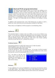
An <strong>ArcGIS</strong> controls-based application<br />
Chapter 1 • Introducing <strong>ArcGIS</strong> <strong>Engine</strong> • 7
OVERVIEW OF ARCGIS ENGINE<br />
<strong>ArcGIS</strong> <strong>Engine</strong> Standard Functionality<br />
· Map interaction<br />
· Map creation<br />
· Map analysis<br />
· Data creation (shapefile and personal geodatabase)<br />
· <strong>Developer</strong> controls<br />
· <strong>Developer</strong> technologies<br />
<strong>ArcGIS</strong> <strong>Engine</strong> Runtime Extensions<br />
· Geodatabase Update<br />
· Spatial<br />
· 3D<br />
· Network<br />
<strong>ArcGIS</strong> <strong>Engine</strong> Runtime deployment options<br />
The availability of the different levels of functionality<br />
is controlled by a software authorization file<br />
that can be configured by the end user or the<br />
developer of the application. For more details on<br />
deploying and configuring the <strong>ArcGIS</strong> <strong>Engine</strong><br />
Runtime, refer to Chapter 5, ‘Licensing and<br />
deployment’.<br />
8 • <strong>ArcGIS</strong> <strong>Engine</strong> <strong>Developer</strong> <strong>Guide</strong><br />
ARCGIS ENGINE RUNTIME<br />
The final component of <strong>ArcGIS</strong> <strong>Engine</strong> is its extensions. All applications built<br />
with the <strong>ArcGIS</strong> <strong>Engine</strong> <strong>Developer</strong> Kit require <strong>ArcGIS</strong> <strong>Engine</strong> Runtime, with<br />
the appropriate license, to execute successfully. <strong>ArcGIS</strong> <strong>Engine</strong> Runtime is the<br />
platform on which <strong>ArcGIS</strong> Desktop is built; this allows users of <strong>ArcGIS</strong> Desktop<br />
applications to execute custom applications based on <strong>ArcGIS</strong> <strong>Engine</strong>, if permitted<br />
by the <strong>ArcGIS</strong> <strong>Engine</strong> application developer. There are several <strong>ArcGIS</strong> <strong>Engine</strong><br />
extensions ranging from standard to enterprise extensions.<br />
Standard <strong>ArcGIS</strong> <strong>Engine</strong> functionality<br />
The standard <strong>ArcGIS</strong> <strong>Engine</strong> Runtime provides the core<br />
functionality of all <strong>ArcGIS</strong> applications. This level of<br />
<strong>ArcGIS</strong> <strong>Engine</strong> Runtime provides the ability to work with<br />
several different raster and vector formats, map presentation<br />
and data creation, along with the ability to explore features<br />
by performing a wide range of spatial or attribute searches.<br />
This level also allows basic data creation, editing of<br />
shapefiles and simple personal geodatabases, and GIS analysis.<br />
Geodatabase Update extension<br />
The Geodatabase Update extension for <strong>ArcGIS</strong> <strong>Engine</strong><br />
Runtime adds the ability to create and update a multiuser<br />
enterprise geodatabase managed with ArcSDE. This includes<br />
the ability to work with schemas and versioned<br />
geodatabases. The Geodatabase Update extension unlocks<br />
<strong>ArcGIS</strong> <strong>Engine</strong> Runtime with the necessary ArcObjects to run custom editing<br />
and advanced geodatabase solutions. These solutions include applications that<br />
deal with GIS data automation and compilation and the construction and maintenance<br />
of geodatabase features. The Geodatabase Update extension provides the<br />
ability to programmatically create geodatabase behaviors, such as topologies,<br />
subtypes, and geometric networks.<br />
<strong>ArcGIS</strong> <strong>Engine</strong> developers with access to an RDBMS via ArcSDE are able to<br />
build and deploy multiuser editing applications to end users that have the <strong>ArcGIS</strong><br />
<strong>Engine</strong> Runtime with the Geodatabase Update extension installed and configured.<br />
Other <strong>ArcGIS</strong> <strong>Engine</strong> extensions<br />
Three additional extensions are available for the <strong>ArcGIS</strong> <strong>Engine</strong> Runtime:<br />
1. Spatial extension—The <strong>ArcGIS</strong> <strong>Engine</strong> Runtime Spatial extension provides a<br />
powerful set of functions that allow applications to create, query, and analyze<br />
cell-based raster data. This type of analysis allows your users to derive information<br />
about their data, identify spatial relationships, find suitable locations,<br />
and calculate the accumulated cost of traveling from one point to another.<br />
Other advanced applications that this extension supports include the calculation<br />
of slope, aspect, and contours against digital elevation models (DEMs).<br />
2. 3D extension—The 3D extension for <strong>ArcGIS</strong> <strong>Engine</strong> Runtime enables the<br />
visualization of data in 3D. This extension supplements standard <strong>ArcGIS</strong>
OVERVIEW OF A RCGIS ENGINE<br />
The StreetMap USA extension functionality is no<br />
longer a separate extension for <strong>ArcGIS</strong> <strong>Engine</strong><br />
but is included as part of the standard <strong>ArcGIS</strong><br />
<strong>Engine</strong> Runtime. The StreetMap USA functions<br />
provide street-level mapping, address matching,<br />
and basic routing for the USA. StreetMap layers<br />
automatically manage, label, and draw features,<br />
such as local landmarks, streets, parks, water<br />
bodies, and other features, resulting in a rich<br />
cartographic street network for the USA.<br />
<strong>Engine</strong> with the components for viewing a surface from multiple viewpoints<br />
and determining what is visible from a chosen location. SceneControl and<br />
GlobeControl provide the interface for viewing multiple layers of 3D and global<br />
data for visualizing data, creating surfaces, and analyzing surfaces.<br />
3. Network Analyst extension—The Network Analyst extension is new at<br />
version 9.1 and enhances the standard <strong>ArcGIS</strong> <strong>Engine</strong> Runtime by adding the<br />
capability of routing, service area analysis, and creating and managing network<br />
datasets. The Network extension allows developers to create and deploy<br />
powerful custom applications for transportation, emergency response, fire,<br />
military, and a host of other purposes.<br />
Chapter 1 • Introducing <strong>ArcGIS</strong> <strong>Engine</strong> • 9
WHO CAN USE ARCGIS ENGINE?<br />
Many users require focused, lightweight access to GIS. They need much less than<br />
a complete GIS application, such as ArcView, yet require access to sophisticated<br />
GIS logic in their applications. In cases in which users need focused, customized<br />
access to GIS, <strong>ArcGIS</strong> <strong>Engine</strong> provides a lower-cost, lightweight option.<br />
STANDALONE APPLICATION DEVELOPERS<br />
There are many potential users of GIS-enhanced applications who are not GIS<br />
professionals and are just not equipped to take advantage of the comprehensive<br />
tools available on the market without a steep learning curve. To provide spatial<br />
solutions to non-GIS users, developers need the ability to build domain-specific,<br />
easy-to-use applications that can incorporate the power of a comprehensive GIS<br />
into a user-friendly experience. These applications, if built from scratch, can be<br />
an overwhelming development effort and may not be time or cost-effective.<br />
You can use the <strong>ArcGIS</strong> <strong>Engine</strong> <strong>Developer</strong> Kit to successfully build standalone<br />
applications. There is a wide variety of types of applications that can be built,<br />
ranging from graphical user interface (GUI) applications to command-line, batchdriven<br />
applications. GUI applications will make use of the extensive <strong>ArcGIS</strong><br />
controls exposed in the developer kit. These controls include everything you need<br />
to build a sophisticated front-end application. You can leverage your chosen API<br />
to integrate the <strong>ArcGIS</strong> controls with other third-party components and create a<br />
unique user interface for your custom <strong>ArcGIS</strong> <strong>Engine</strong> application.<br />
An application built in Java using the<br />
GlobeControl<br />
ARCGIS DESKTOP USERS<br />
ArcMap, one of the <strong>ArcGIS</strong> Desktop applications, is an excellent way to create<br />
data and author maps for use in custom applications. The MapControl and<br />
PageLayoutControl provided with <strong>ArcGIS</strong> <strong>Engine</strong> can work with the map documents<br />
created in ArcMap. SceneControl and GlobeControl can display documents<br />
10 • <strong>ArcGIS</strong> <strong>Engine</strong> <strong>Developer</strong> <strong>Guide</strong>
WHO CAN USE ARCGIS ENGINE?<br />
authored in the ArcScene and ArcGlobe applications. Using the <strong>ArcGIS</strong><br />
Desktop applications to create and manage maps used in custom applications can<br />
save you much development time and effort. <strong>ArcGIS</strong> Desktop also provides tools<br />
to build and manage geodatabases, shapefiles, and other forms of spatial data.<br />
The underlying components of <strong>ArcGIS</strong> Desktop are the same ArcObjects components<br />
that make up <strong>ArcGIS</strong> <strong>Engine</strong>. This allows every <strong>ArcGIS</strong> Desktop user the<br />
ability to run <strong>ArcGIS</strong> <strong>Engine</strong> applications. You can develop applications based on<br />
<strong>ArcGIS</strong> <strong>Engine</strong> and deploy them to <strong>ArcGIS</strong> Desktop users or extend<br />
ArcToolbox with a custom toolset built with the <strong>ArcGIS</strong> <strong>Engine</strong> developer kit.<br />
ARCGIS SERVER USERS<br />
<strong>ArcGIS</strong> Server administrators can provide server objects and Web services to<br />
<strong>ArcGIS</strong> <strong>Engine</strong> applications. This allows the integration of desktop functionality<br />
with server functionality. It is also important to remember that the GIS functionality<br />
exposed via the ArcObjects that compose <strong>ArcGIS</strong> <strong>Engine</strong> is the same in<br />
<strong>ArcGIS</strong> Server, meaning that <strong>ArcGIS</strong> Server, <strong>Engine</strong>, and Desktop have the same<br />
core ArcObjects.<br />
`<br />
`<br />
`<br />
ArcObjects<br />
ArcObjects<br />
ArcObjects<br />
Proxies<br />
<strong>ArcGIS</strong> <strong>Engine</strong><br />
ArcObjects<br />
Proxies<br />
<strong>ArcGIS</strong> Desktop<br />
Desktop applications<br />
(single user)<br />
`<br />
Server applications<br />
(Multiuser)<br />
Server Object<br />
Manager<br />
ArcObjects<br />
Proxies<br />
.NET/Java ADF<br />
ArcObjects<br />
Proxies<br />
.NET/Java ADF<br />
`<br />
Server Object Containers<br />
ArcObjects<br />
ArcObjects<br />
ArcObjects<br />
GIS Server<br />
Chapter 1 • Introducing <strong>ArcGIS</strong> <strong>Engine</strong> • 11
ARCGIS ENGINE CAPABILITIES<br />
The items listed at right, if deployed, are<br />
included in the standard <strong>ArcGIS</strong> <strong>Engine</strong> Runtime<br />
functionality and would not require any of the<br />
additional extensions.<br />
A software authorization file controls the<br />
availability of the various levels of <strong>ArcGIS</strong> <strong>Engine</strong><br />
Runtime functionality. For more details on<br />
deploying and configuring the <strong>ArcGIS</strong> <strong>Engine</strong><br />
Runtime, refer to Chapter 5, ‘Licensing and<br />
deployment’.<br />
The capabilities of <strong>ArcGIS</strong> <strong>Engine</strong> are extensive. As an <strong>ArcGIS</strong> <strong>Engine</strong> developer,<br />
you can implement these and many other functions using its developer kit:<br />
• Display a map with multiple map layers, such as roads, streams, and boundaries.<br />
• Pan and zoom throughout a map.<br />
• Identify features on a map.<br />
• Search for and find features on a map.<br />
• Display labels with text from field values.<br />
• Draw images from aerial photography or satellite imagery.<br />
• Draw graphic features, such as points, lines, circles, and polygons.<br />
• Draw descriptive text.<br />
• Select features along lines and inside boxes, areas, polygons, and circles.<br />
• Select features within a specified distance of other features.<br />
• Find and select features with a Structured Query Language (SQL) expression.<br />
• Render features with thematic methods, such as value map, class breaks, and<br />
dot density.<br />
• Dynamically display real-time or time series data.<br />
• Find locations on a map by geocoding addresses or street intersections.<br />
• Transform the coordinate system of your map data.<br />
• Perform geometric operations on shapes to create buffers; calculate differences;<br />
and find intersections, unions, or inverse intersections of shapes.<br />
• Manipulate the shape or rotation of a map.<br />
• Create and update geographic features and their attributes.<br />
EDITING FEATURES<br />
<strong>ArcGIS</strong> <strong>Engine</strong> developer kit enables you to build applications that create,<br />
modify, and remove vector-shaped features in a geodatabase or shapefile. The<br />
standard <strong>ArcGIS</strong> <strong>Engine</strong> Runtime is used to run applications that edit shapefiles<br />
or the simple features of a personal geodatabase. However, leveraging the full<br />
function of the enterprise geodatabase, the Geodatabase Update extension of the<br />
<strong>ArcGIS</strong> <strong>Engine</strong> Runtime is required.<br />
12 • <strong>ArcGIS</strong> <strong>Engine</strong> <strong>Developer</strong> <strong>Guide</strong>
ARCGIS ENGINE CAPABILITIES<br />
SPATIAL MODELING AND ANALYSIS<br />
You can extend the capabilities of <strong>ArcGIS</strong> <strong>Engine</strong> by adding the Spatial extension<br />
to <strong>ArcGIS</strong> <strong>Engine</strong> Runtime. This extension provides a broad range of powerful<br />
spatial modeling and analysis functions. You can create, query, map, and<br />
analyze cell-based raster data; perform integrated raster or vector analysis; derive<br />
new information from existing data; query information across multiple data<br />
layers; and fully integrate cell-based raster data with vector data in a custom<br />
<strong>ArcGIS</strong> <strong>Engine</strong> application.<br />
An application, developed using the<br />
MapControl, that utilizes the Spatial extension<br />
for the <strong>ArcGIS</strong> <strong>Engine</strong> Runtime<br />
For example, you can:<br />
• Convert features (points, lines, or polygons) to raster.<br />
• Create raster buffers based on distance or proximity from features or rasters.<br />
• Generate density maps from point features.<br />
• Derive contours, slope, viewshed, aspect, and hillshades.<br />
• Perform grid classification and display.<br />
• Use data from standard formats including TIFF, BIL, IMG, USGS DEM,<br />
SDTS, DTED, and many others.<br />
Chapter 1 • Introducing <strong>ArcGIS</strong> <strong>Engine</strong> • 13
ARCGIS ENGINE CAPABILITIES<br />
Java code for the inset GlobeControl-based<br />
application<br />
3D VISUALIZATION AND MORE<br />
The <strong>ArcGIS</strong> <strong>Engine</strong> Runtime 3D extension extends the capabilities of <strong>ArcGIS</strong><br />
<strong>Engine</strong> even further by enabling you to build applications that effectively visualize<br />
and analyze surface and globe data using SceneControl and GlobeControl. You can<br />
create applications that view a surface from multiple viewpoints, query a surface,<br />
determine what is visible from a chosen location on a<br />
surface, and display a realistic perspective image by<br />
draping raster and vector data over a surface.<br />
You can, for example:<br />
• Display ArcScene and ArcGlobe documents.<br />
• Perform interactive perspective viewing, including pan<br />
and zoom, rotate, tilt, and fly-through simulations, for<br />
presentation and analysis.<br />
• Display real-world surface features, such as buildings.<br />
• Perform viewshed and line-of-sight analysis, spot<br />
height interpolation, profiling, and steepest path<br />
determination.<br />
Display of a<br />
SceneControlbased<br />
application<br />
14 • <strong>ArcGIS</strong> <strong>Engine</strong> <strong>Developer</strong> <strong>Guide</strong>
ARCGIS ENGINE CAPABILITIES<br />
NETWORK ANALYSIS<br />
The Network extension to <strong>ArcGIS</strong> <strong>Engine</strong> is new at version 9.1 and provides<br />
developers with the capability to create applications that utilize network data in a<br />
variety of formats and creating and editing network datasets. The following<br />
network functions are available to developers:<br />
• Path—Find a path through a set of network locations that minimizes some<br />
impedance (cost) attribute<br />
• Tour—Determine the minimum-cost path to reach a series of stops; also<br />
determines the order in which the stops are visited.<br />
• Directions—Generate a series of directions for the user.<br />
• Closest Facility—Given a network location (an incident) finds the closest<br />
facilities.<br />
• Service Areas—Find all network elements within a given distance from a<br />
network location.<br />
Chapter 1 • Introducing <strong>ArcGIS</strong> <strong>Engine</strong> • 15
GETTING STARTED<br />
Some examples of <strong>ArcGIS</strong> <strong>Engine</strong> applications<br />
are provided in Chapter 6, ‘<strong>Developer</strong> scenarios’.<br />
Additional samples are included with the <strong>ArcGIS</strong><br />
<strong>Developer</strong> Help system.<br />
Once you have the <strong>ArcGIS</strong> <strong>Engine</strong> <strong>Developer</strong> Kit installed, you will need to<br />
register your product before you can start developing custom applications. At the<br />
end of the installation of the <strong>ArcGIS</strong> <strong>Engine</strong> <strong>Developer</strong> Kit, the Software<br />
Authorization wizard will start. Follow the steps through the wizard to authorize<br />
<strong>ArcGIS</strong> <strong>Engine</strong> <strong>Developer</strong> Kit. The ESRI Customer Service Web site<br />
(http://service.esri.com) can also be used to obtain your authorization file. To use<br />
the Web site or the wizard, you will need to know your product registration<br />
number. With the <strong>ArcGIS</strong> <strong>Engine</strong> <strong>Developer</strong> installed and authorized for use, you<br />
are ready to get started. However, good applications require careful planning;<br />
working with ArcObjects is no exception. Before beginning your development,<br />
feel free to read through and use, as necessary, the discussions and checklists in<br />
this section. They are provided to help you formulate your plans and ensure you’re<br />
getting started on the right foot.<br />
DETERMINING THE TYPE OF APPLICATION<br />
A wide variety of applications can be developed with <strong>ArcGIS</strong> <strong>Engine</strong>. These<br />
applications vary from simple consoles that perform operations, such as database<br />
editing and analyses, to more complex Windows applications that contain controls<br />
and visual components for user interaction and geographic data display. In<br />
general, there are three types of <strong>ArcGIS</strong> <strong>Engine</strong> applications:<br />
1. Standalone, nonvisual applications, such as console and utility applications<br />
2. Standalone, visual applications, such as Windows and control-based applications<br />
3. Embedded applications, such as components that are inserted into existing<br />
applications<br />
Ultimately, the type of application you develop will depend on the functional<br />
requirements of the project at hand.<br />
Checklist:<br />
! What type of application are you developing? Nonvisual, visual, or<br />
embedded?<br />
! Do you plan to migrate the functionality to <strong>ArcGIS</strong> Desktop or<br />
<strong>ArcGIS</strong> Server products?<br />
WebSphere Studio<br />
Visual Studio .NET<br />
! What platform do you want to support now and in the future?<br />
Windows? Linux ® ? Both?<br />
CHOOSING AN API AND DEVELOPMENT ENVIRONMENT<br />
Since <strong>ArcGIS</strong> <strong>Engine</strong> <strong>Developer</strong> Kit provides four developer APIs—COM,<br />
.NET, Java, and C++. The different APIs can be leveraged in several different<br />
supported development environments. ESRI recommends and supports the<br />
following integrated development environments (IDEs) or compilers when<br />
working with <strong>ArcGIS</strong> <strong>Engine</strong>.<br />
COM<br />
• Visual Basic 6 sp3 or later<br />
• Visual C++ 6 sp3 or later<br />
16 • <strong>ArcGIS</strong> <strong>Engine</strong> <strong>Developer</strong> <strong>Guide</strong>
GETTING STARTED<br />
Throughout most of this book, VB6 is used as<br />
the language to illustrate most coding concepts<br />
and is often the easiest language to learn when<br />
getting started. See Chapter 4, ‘<strong>Developer</strong><br />
environments’, for programming guidelines for<br />
VB and some of the other environments<br />
supported by the <strong>ArcGIS</strong> <strong>Engine</strong> APIs.<br />
• Visual C++ (Visual Studio .NET 2003)<br />
.NET<br />
• C# (Visual Studio .NET 2003 with .NET Framework 1.1)<br />
• VB.NET (Visual Studio .NET 2003 with .NET Framework 1.1)<br />
Java<br />
• Eclipse v. 3.0 or 3.0.1<br />
• JBuilder X<br />
• NetBeans 3.6<br />
C++ (Compilers)<br />
• Visual C++ sp3 or later for Windows<br />
• Visual C++ (VS.NET 2003) for Windows<br />
• GCC 3.2 C++ for Linux (Intel)<br />
• WorkShop 6 Update 2 for Sun Solaris<br />
The environment you choose to develop with will ultimately depend on your<br />
programming skills, the functionality you wish to provide end users, and whether<br />
or not you are integrating with other existing applications or technologies.<br />
Checklist:<br />
! What development environment and language are you the most familiar<br />
with?<br />
! Which <strong>ArcGIS</strong> <strong>Engine</strong> API do you plan to use?<br />
! Which development environment and language is best suited for the<br />
type of the development you want to undertake?<br />
Each functional group of ArcObjects, or library,<br />
used must be referenced in your development<br />
environment for your application to compile and<br />
run successfully. The various libraries available in<br />
<strong>ArcGIS</strong> <strong>Engine</strong> are discussed in detail in<br />
Chapter 2, ‘<strong>ArcGIS</strong> software architecture’.<br />
<strong>ArcGIS</strong> <strong>Developer</strong> Online can be accessed from<br />
http://arcgisdeveloperonline.esri.com.<br />
DEVELOPING YOUR APPLICATION<br />
At this point, assuming that a proper project development plan is in place, you are<br />
ready to dive into the <strong>ArcGIS</strong> <strong>Engine</strong> <strong>Developer</strong> Kit and start developing your<br />
application. You may want to start by identifying the libraries and objects that<br />
will be necessary to provide the functionality for the application. Use the developer<br />
help resources to assist you in this process, including the <strong>ArcGIS</strong> <strong>Developer</strong><br />
Help system, the <strong>Developer</strong> <strong>Guide</strong> series, samples included in the help system,<br />
and the <strong>ArcGIS</strong> <strong>Developer</strong> Online site.<br />
Checklist:<br />
! Identify the ArcObjects functionality required.<br />
! What <strong>ArcGIS</strong> <strong>Engine</strong> library references will be required?<br />
! What <strong>ArcGIS</strong> license will be required to run the application?<br />
! Are <strong>ArcGIS</strong> <strong>Engine</strong> extensions required?<br />
! How do you plan to deploy the application?<br />
! Have you implemented the correct license check-out code?<br />
Chapter 1 • Introducing <strong>ArcGIS</strong> <strong>Engine</strong> • 17
GETTING STARTED<br />
DEPLOYING YOUR APPLICATION<br />
Application deployment is an issue that should be considered long before application<br />
development begins. <strong>ArcGIS</strong> <strong>Engine</strong> applications can be deployed in a number<br />
of ways, and it is possible to have a number of end user software and license<br />
configurations. Therefore, there are a number of issues that you need to consider.<br />
Checklist:<br />
! Will users already have <strong>ArcGIS</strong> <strong>Engine</strong> Runtime installed? No ESRI<br />
products installed?<br />
! What <strong>ArcGIS</strong> license will your end users have on their systems?<br />
ArcInfo, ArcEditor, or ArcView? Which license will your application<br />
check for and use?<br />
Chapter 5, ‘Licensing and deployment’, discusses<br />
the various aspects of this checklist.<br />
! How should you package and deploy the application?<br />
! Will you need to provide new versions in the future?<br />
! How will you distribute the application?<br />
18 • <strong>ArcGIS</strong> <strong>Engine</strong> <strong>Developer</strong> <strong>Guide</strong>
USING THIS BOOK<br />
This book, <strong>ArcGIS</strong> <strong>Engine</strong> <strong>Developer</strong> <strong>Guide</strong>, is an introduction for developers who<br />
want to build standalone GIS applications. This guide will help you, as the developer,<br />
become familiar with the <strong>ArcGIS</strong> <strong>Engine</strong> object model by introducing all<br />
the <strong>ArcGIS</strong> <strong>Engine</strong> developer kit components, discussing relevant aspects of<br />
building applications, introducing supported APIs, and providing developer<br />
scenarios that produce real-world GIS applications.<br />
To serve the widest base of developers, most of the code samples provided<br />
within this book use the COM Visual Basic 6 API. However, the developer<br />
scenarios cover the full range of supported APIs, and a chapter is devoted to<br />
API-specific usages.<br />
The first two chapters of this book provide an overview of <strong>ArcGIS</strong> <strong>Engine</strong> and<br />
its capabilities, including architecture and components. The remaining chapters<br />
focus on developing application usages of each particular supported API.<br />
CHAPTER GUIDE<br />
Chapter 1, ‘Introducing <strong>ArcGIS</strong> <strong>Engine</strong>’, gives developers an overview of the<br />
<strong>ArcGIS</strong> <strong>Engine</strong> product, its capabilities, and developer resources.<br />
Chapter 2, ‘<strong>ArcGIS</strong> software architecture’, describes <strong>ArcGIS</strong> <strong>Engine</strong> architecture<br />
and how the software components interact inside the system.<br />
‘Developing with <strong>ArcGIS</strong> controls’ is detailed in Chapter 3. It describes each of<br />
the controls and provides some considerations for their use in application development.<br />
Chapter 4, ‘<strong>Developer</strong> environments’, introduces you to the multiple APIs supported<br />
by <strong>ArcGIS</strong> <strong>Engine</strong>. This chapter guides you through each API from the<br />
basics to advanced usage topics.<br />
‘Licensing and deployment’ issues are addressed in Chapter 5. It details the licensing<br />
options and discusses deployment strategies for your application, including<br />
initialization and license checking.<br />
Chapter 6, ‘<strong>Developer</strong> scenarios’, guides you through the creation and deployment<br />
of several types of standalone applications utilizing each of the supported APIs.<br />
This book also contains a number of appendixes that provide detailed information<br />
about the object model diagrams available in the <strong>ArcGIS</strong> <strong>Developer</strong> Help<br />
system and additional developer resources.<br />
Chapter 1 • Introducing <strong>ArcGIS</strong> <strong>Engine</strong> • 19
DEVELOPER RESOURCES<br />
The following topics describe some of the additional resources available to<br />
<strong>ArcGIS</strong> developers. More in-depth coverage on the resources available to developers<br />
is covered in Appendix B.<br />
ARCGIS DEVELOPER HELP SYSTEM<br />
The <strong>ArcGIS</strong> <strong>Developer</strong> Help system is an essential resource for both the beginning<br />
and experienced ArcObjects developers. It contains information on developing<br />
with ArcObjects including sample code, technical documents, and object<br />
model diagrams. In addition, it also serves as a reference guide containing information<br />
on every object within ArcObjects. The help system is available to Visual<br />
Basic, .NET, Java, and C++ developers. You can start the <strong>ArcGIS</strong> <strong>Developer</strong><br />
Help system through the <strong>ArcGIS</strong> program group from the Windows Start button.<br />
The VB6 version of <strong>ArcGIS</strong> <strong>Developer</strong> Help is<br />
installed in a typical installation. Follow the<br />
custom installation procedures to access the<br />
C++, Java, or .NET versions.<br />
THE ARCGIS DEVELOPER SERIES<br />
This book is one in a series of books for <strong>ArcGIS</strong> developers.<br />
The <strong>ArcGIS</strong> Desktop <strong>Developer</strong> <strong>Guide</strong> is for developers who want to customize or<br />
extend one of the <strong>ArcGIS</strong> Desktop applications, such as ArcMap or ArcCatalog.<br />
<strong>Developer</strong>s can use Visual Basic for Applications (VBA) to customize and either<br />
Visual Basic, Visual C++, or .NET to extend the applications.<br />
The <strong>ArcGIS</strong> Server Administrator and <strong>Developer</strong> <strong>Guide</strong> is for developers who want to<br />
use <strong>ArcGIS</strong> Server to build custom server applications. Server developers can<br />
build Web services and Web applications that do simple mapping or include<br />
advanced GIS functionality. Several scenarios illustrate with code examples some<br />
of the different types of applications that can be developed using one of the<br />
multiple <strong>ArcGIS</strong> Server <strong>Developer</strong> Kits. This book also serves as the administration<br />
guide to <strong>ArcGIS</strong> Server.<br />
20 • <strong>ArcGIS</strong> <strong>Engine</strong> <strong>Developer</strong> <strong>Guide</strong>
DEVELOPER RESOURCES<br />
ESRI DEVELOPER NETWORK ONLINE<br />
ESRI <strong>Developer</strong> Network (EDN) online—http://edn.esri.com—is a central<br />
location to find and view developer-focused articles, code samples, and other<br />
resources related to <strong>ArcGIS</strong>, ArcIMS, ArcSDE, and ArcWeb Services. In addition,<br />
EDN provides a number of community-building areas intended to promote<br />
your collaboration and interaction with other GIS developers and ESRI<br />
staff. The site is continually updated, making it the most up-to-date reference for<br />
developers.<br />
The ESRI <strong>Developer</strong> Network at<br />
http://edn.esri.com<br />
The ESRI Support Center at<br />
http://support.esri.com<br />
ESRI SUPPORT CENTER<br />
The ESRI Support Center at http://support.esri.com contains software information,<br />
technical documents, samples, forums, and a knowledge base for all <strong>ArcGIS</strong><br />
products.<br />
<strong>ArcGIS</strong> developers can take advantage of the forums, knowledge base, and<br />
samples sections to aid in development of their <strong>ArcGIS</strong> applications.<br />
TRAINING<br />
ESRI offers a number of instructor-led and Web-based training courses for the<br />
<strong>ArcGIS</strong> developer. These courses range from introductory level for VBA to the<br />
more advanced courses in component development for <strong>ArcGIS</strong> Desktop, <strong>Engine</strong>,<br />
and Server.<br />
For more information, visit http://www.esri.com and click the Training and Events<br />
tab.<br />
The ESRI Virtual Campus can be found directly at http://campus.esri.com.<br />
The ESRI Virtual Campus at<br />
http://campus.esri.com<br />
Chapter 1 • Introducing <strong>ArcGIS</strong> <strong>Engine</strong> • 21
2<br />
<strong>ArcGIS</strong> software<br />
architecture<br />
<strong>ArcGIS</strong> has evolved over several releases of the technology to be a modular,<br />
scalable, cross-platform architecture implemented by a set of software<br />
components called ArcObjects.<br />
This chapter focuses on the main themes of this evolution at <strong>ArcGIS</strong> 9 and<br />
introduces the reader to the various libraries that<br />
compose the <strong>ArcGIS</strong> system.
ARCGIS SOFTWARE ARCHITECTURE<br />
For a detailed explanation of COM, see the<br />
COM section of Chapter 4, '<strong>Developer</strong><br />
environments'.<br />
<strong>Developer</strong><br />
Components<br />
Map<br />
Presentation<br />
Map<br />
Analysis<br />
Data<br />
Access<br />
Base<br />
Services<br />
<strong>ArcGIS</strong> <strong>Engine</strong><br />
The <strong>ArcGIS</strong> software architecture supports a number of products, each with its<br />
unique set of requirements. ArcObjects, the components that make up <strong>ArcGIS</strong>,<br />
are designed and built to support this. This chapter introduces ArcObjects.<br />
ArcObjects is a set of platform-independent software components, written in<br />
C++, that provides services to support GIS applications on the desktop, in the<br />
form of thick and thin clients, and on the server.<br />
As stated, the language chosen to develop ArcObjects was C++; in addition to<br />
this language, ArcObjects makes use of the Microsoft Component Object Model.<br />
COM is often thought of as simply specifying how objects are implemented and<br />
built in memory and how these objects communicate with one another. While<br />
this is true, COM also provides a solid infrastructure at the operating system level<br />
to support any system built using COM. On Microsoft Windows operating systems,<br />
the COM infrastructure is built directly into the operating system. For<br />
operating systems other than Microsoft Windows, this infrastructure must be<br />
provided for the ArcObjects system to function.<br />
Not all ArcObjects components are created equally. The requirements of a particular<br />
object, in addition to its basic functionality, vary depending on the final<br />
end use of the object. This end use broadly falls into one of the three <strong>ArcGIS</strong><br />
product families:<br />
• <strong>ArcGIS</strong> <strong>Engine</strong>—Use of the object is within a custom application. Objects<br />
within <strong>ArcGIS</strong> <strong>Engine</strong> must support a variety of uses; simple map dialog<br />
boxes, multithreaded servers, and complex Windows desktop applications are<br />
all possible uses of <strong>ArcGIS</strong> <strong>Engine</strong> objects. The dependencies of the objects<br />
within <strong>ArcGIS</strong> <strong>Engine</strong> must be well understood. The impact of adding dependencies<br />
external to ArcObjects must be carefully reviewed, since new dependencies<br />
may introduce undesirable complexity to the installation of the application<br />
built on <strong>ArcGIS</strong> <strong>Engine</strong>.<br />
• <strong>ArcGIS</strong> Server—The object is used within the server framework, where<br />
clients of the object are most often remote. The remoteness of the client can<br />
vary from local, possibly on the same machine or network, to distant, where<br />
clients can be on the Internet. Objects running within the server must be<br />
scalable and thread safe to allow execution in a multithreaded environment.<br />
• <strong>ArcGIS</strong> Desktop—Use of the object is within one of the <strong>ArcGIS</strong> Desktop<br />
applications. <strong>ArcGIS</strong> Desktop applications have a rich user experience, with<br />
applications containing many dialog boxes and property pages that allow end<br />
users to work effectively with the functionality of the object. Objects that<br />
contain properties that are to be modified by users of these applications<br />
should have property pages created for these properties. Not all objects<br />
require property pages.<br />
24 • <strong>ArcGIS</strong> <strong>Engine</strong> <strong>Developer</strong> <strong>Guide</strong>
ARCGIS SOFTWARE ARCHITECTURE<br />
User<br />
Interface<br />
Web<br />
Development<br />
Framework<br />
Map<br />
Presentation<br />
Map<br />
Analysis<br />
Data<br />
Access<br />
Base<br />
Services<br />
Extensions<br />
Applications<br />
<strong>ArcGIS</strong> Server<br />
Map<br />
Presentation<br />
Map<br />
Analysis<br />
Data<br />
Access<br />
Base Services<br />
<strong>ArcGIS</strong> Desktop<br />
Many of the ArcObjects components that make up <strong>ArcGIS</strong> are used within all three<br />
of the <strong>ArcGIS</strong> products. The product diagrams on these pages show that the objects<br />
within the broad categories of base services, data access, map analysis, and map<br />
presentation are contained in all three products. These four categories contain the<br />
majority of the GIS functionality exposed to developers and users in <strong>ArcGIS</strong>.<br />
This commonality of function among all the products is important for developers to<br />
understand, since it means that when working in a particular category, much of the<br />
development effort can be transferred among the <strong>ArcGIS</strong> products with little<br />
change to the software. After all, this is exactly how the <strong>ArcGIS</strong> architecture is<br />
developed. Code reuse is a major benefit of building a modular architecture, but<br />
code reuse does not simply come from creating components in a modular fashion.<br />
The <strong>ArcGIS</strong> architecture provides rich functionality to the developer, but it is not a<br />
closed system. The <strong>ArcGIS</strong> architecture is extendable by developers external to<br />
ESRI. <strong>Developer</strong>s have been extending the architecture for a number of years, and<br />
the <strong>ArcGIS</strong> 9 architecture is no different; it, too, can be extended. However,<br />
<strong>ArcGIS</strong> 9 introduces many new possibilities for the use of objects created by ESRI<br />
and you. To realize these possibilities, components must meet additional requirements<br />
to ensure that they will operate successfully within this new and significantly<br />
enhanced <strong>ArcGIS</strong> system. Some of the changes from <strong>ArcGIS</strong> 8 to <strong>ArcGIS</strong> 9 may<br />
appear superficial, an example being the breakup of the type libraries into smaller<br />
libraries. That, along with the fact that the objects with their methods and properties<br />
that were present at 8.3 are still available at 9.0, masks the fact that internally<br />
ArcObjects has undergone some significant work.<br />
The main focus of the changes made to the <strong>ArcGIS</strong> architecture at 9.0 revolves<br />
around four key concepts:<br />
• Modularity—A modular system where the dependencies between components<br />
are well-defined in a flexible system.<br />
• Scalability—ArcObjects must perform well in all intended operating environments,<br />
from single user desktop applications to multiuser and multithreaded<br />
server applications.<br />
• Multiple Platform Support—ArcObjects for <strong>ArcGIS</strong> <strong>Engine</strong> and Server should<br />
be capable of running on multiple computing platforms.<br />
• Compatibility—ArcObjects 9 should remain equivalent, both functionally and<br />
programmatically, to ArcObjects 8.3.<br />
MODULARITY<br />
The esriCore object library, shipped as part of <strong>ArcGIS</strong> 8.3, effectively packaged all<br />
ArcObjects components into one large block of GIS functionality; there was no<br />
distinction between components. The ArcObjects components were divided into<br />
smaller groups of components, these groups being packaged in Dynamic Link<br />
Libraries (DLLs). The one large library, while simplifying the task of development<br />
for external developers, prevented the software from being modular. Adding the<br />
type information to all the DLLs, while possible, would have greatly increased the<br />
burden on external developers and, hence, was not an option. In addition, the DLL<br />
structure did not always reflect the best modular breakup of software components<br />
based on functionality and dependency.<br />
Chapter 2 • <strong>ArcGIS</strong> software architecture • 25
ARCGIS SOFTWARE ARCHITECTURE<br />
ESRI has developed a modular architecture for<br />
<strong>ArcGIS</strong> 9 by a process of analyzing features and<br />
functions and matching those with end user<br />
requirements and deployment options based on<br />
the three <strong>ArcGIS</strong> product families. <strong>Developer</strong>s<br />
who have extended the <strong>ArcGIS</strong> 8 architecture<br />
with custom components are encouraged to go<br />
through the same process to restructure their<br />
source code into similar modular structures.<br />
An obvious functionality split to make is user<br />
interface and nonuser interface code. UI libraries<br />
tend to be included only with the <strong>ArcGIS</strong><br />
Desktop products.<br />
For this discussion, thread safety refers to<br />
concurrent object access from multiple threads.<br />
There is always a trade-off in performance and manageability when considering<br />
architecture modularity. For each criterion, thought is given to the end use and<br />
the modularity required for support that. For example, the system could be<br />
divided into many small DLLs with only a few objects in each. Although this<br />
provides a flexible system for deployment options, at minimum memory requirements,<br />
it would affect performance due to the large number of DLLs being<br />
loaded and unloaded. Conversely, one large DLL containing all objects is not a<br />
suitable solution either. Knowing the requirements of the components allows<br />
them to be effectively packaged into DLLs.<br />
The <strong>ArcGIS</strong> 9 architecture is divided into a number of libraries. It is possible for<br />
a library to have any number of DLLs and EXEs within it. The requirements that<br />
components must meet to be within a library are well-defined. For instance, a<br />
library, such as esriGeometry (from the base services set of modules), has the<br />
requirements of being thread safe, scalable, without user interface components,<br />
and deployable on a number of computing platforms. These requirements are<br />
different from libraries, such as esriArcMap (from the applications category),<br />
which has user interface components and is a Windows-only library.<br />
All the components in the library will share the same set of requirements placed<br />
on the library. It is not possible to subdivide a library into smaller pieces for<br />
distribution. The library defines the namespace for all components within it and is<br />
seen in a form suitable for your chosen API.<br />
• Type Library—COM<br />
• .NET Interop Assembly—.NET<br />
• Java Package—Java<br />
• Header File—C++<br />
SCALABILITY<br />
The ArcObjects components within <strong>ArcGIS</strong> <strong>Engine</strong> and <strong>ArcGIS</strong> Server must be<br />
scalable. <strong>Engine</strong> objects are scalable because they can be used in many different<br />
types of applications; some require scalability, while others do not. Server objects<br />
are required to be scalable to ensure that the server can handle many users connecting<br />
to it, and as the configuration of the server grows, so does the performance<br />
of the ArcObjects components running on the server.<br />
The scalability of a system is achieved using a number of variables involving the<br />
hardware and software of the system. In this regard, ArcObjects supports<br />
scalability with the effective use of memory within the objects and the ability to<br />
execute the objects within multithreaded processes.<br />
There are two considerations when multithreaded applications are discussed:<br />
thread safety and scalability. It is important for all objects to be thread safe, but<br />
simply having thread-safe objects does not automatically mean that creating<br />
multithreaded applications is straightforward or that the resulting application<br />
will provide vastly improved performance.<br />
The ArcObjects components contained in the base services, data access, map<br />
analysis, and map presentation categories are all thread safe. This means that<br />
application developers can use them in multithreaded applications; however,<br />
26 • <strong>ArcGIS</strong> <strong>Engine</strong> <strong>Developer</strong> <strong>Guide</strong>
ARCGIS SOFTWARE ARCHITECTURE<br />
The classic singleton per process model means<br />
that all threads of an application will still access<br />
the main thread hosting the singleton objects.<br />
This effectively reduces the application to a<br />
single-threaded application.<br />
Microsoft Windows is a little endian platform,<br />
and Sun Solaris is a big endian platform.<br />
While the aim of <strong>ArcGIS</strong> releases is to limit the<br />
change in the APIs, developers should still test<br />
their software thoroughly with later releases.<br />
programmers must still write multithreaded code in such a way as to avoid application<br />
failures due to deadlock situations, and so forth.<br />
In addition to the ArcObjects components being thread safe for <strong>ArcGIS</strong> 9, the<br />
apartment threading model used by ArcObjects was analyzed to ensure that<br />
ArcObjects could be run efficiently in a multithreaded process. A model referred<br />
to as “Threads in Isolation” was used to ensure that the ArcObjects architecture is<br />
used efficiently.<br />
This model works by reducing cross-thread communication to an absolute minimum<br />
or, better still, removing it entirely. For this to work, the singleton objects<br />
at <strong>ArcGIS</strong> 9 were changed to be singletons per thread and not singletons per<br />
process. The resource overhead of hosting multiple singletons in a process was<br />
outweighed by the performance gain of stopping cross-thread communication<br />
where the singleton object is created in one thread (normally the Main STA) and<br />
the accessing object is in another thread.<br />
<strong>ArcGIS</strong> is an extensible system, and for the Threads in Isolation model to work,<br />
all singleton objects must adhere to this rule. If you are creating singleton objects<br />
as part of your development, you must ensure that these objects adhere to the<br />
rule.<br />
MULTIPLE PLATFORM SUPPORT<br />
As stated earlier, ArcObjects components are C++ objects, meaning that any<br />
computing platform with a C++ compiler can potentially be a platform for<br />
ArcObjects. In addition to the C++ compiler, the platform must also support<br />
some basic services required by ArcObjects.<br />
Although many of the platform differences do not affect the way in which<br />
ArcObjects components are developed, there are areas where differences do<br />
affect the way code is developed. The byte order of different computing architectures<br />
varies between little endian and big endian. This is most readily seen when<br />
objects read and write data to disk. Data written using one computing platform<br />
will not be compatible if read using another platform, unless some decoding is<br />
performed. All the <strong>ArcGIS</strong> <strong>Engine</strong> and <strong>ArcGIS</strong> Server objects support this multiple<br />
platform persistence model. ArcObjects components always persist themselves<br />
using the little endian model; when the objects read persisted data, it is<br />
converted to the appropriate native byte order. In addition to the byte order<br />
differences, there are other areas of functionality that differ between platforms;<br />
the directory structure, for example, uses different separators for Windows and<br />
UNIX—“\” and “/”, respectively. Another example is the platform-specific areas<br />
of functionality, such as Object Linking and Embedding Database (OLE DB).<br />
COMPATIBILITY<br />
Maintaining compatibility of the <strong>ArcGIS</strong> system between releases is important to<br />
ensure that external developers are not burdened with changing their code to<br />
work with the latest release of the technology. Maintaining compatibility at the<br />
object level was a primary goal of the <strong>ArcGIS</strong> 9 development effort. Although<br />
this object-level compatibility has been maintained, there are some changes<br />
between the <strong>ArcGIS</strong> 8 and <strong>ArcGIS</strong> 9 architectures that will affect developers,<br />
mainly related to the compilation of the software.<br />
Chapter 2 • <strong>ArcGIS</strong> software architecture • 27
ARCGIS SOFTWARE ARCHITECTURE<br />
Although the changes required for software created for use with <strong>ArcGIS</strong> 8 to<br />
work with <strong>ArcGIS</strong> 9 are minimal, it is important to understand that to realize any<br />
existing investment in the ArcObjects architecture at <strong>ArcGIS</strong> 9, you must review<br />
your developments with respect to <strong>ArcGIS</strong> <strong>Engine</strong>, <strong>ArcGIS</strong> Server, and <strong>ArcGIS</strong><br />
Desktop.<br />
ESRI understands the importance of a unified software architecture and has<br />
made numerous changes for <strong>ArcGIS</strong> 9 so the investment in ArcObjects can be<br />
realized on multiple products. If you have been involved in creating extensions to<br />
the <strong>ArcGIS</strong> architecture for <strong>ArcGIS</strong> 8, you should think about how the new<br />
<strong>ArcGIS</strong> 9 architecture affects the way your components are implemented.<br />
28 • <strong>ArcGIS</strong> <strong>Engine</strong> <strong>Developer</strong> <strong>Guide</strong>
ARCGIS APPLICATION PROGRAMMING INTERFACES<br />
It is important not to confuse the Visual C++<br />
support available through the COM API and the<br />
native C++ API.<br />
Since ArcObjects is developed in C++, there are<br />
some cases in which data types compatible with<br />
C++ have been used for performance reasons.<br />
These performance considerations mostly affect<br />
the internals of ArcObjects; therefore, using one<br />
of the generic interfaces should not<br />
adversely affect performance of your<br />
ArcObjects developments.<br />
The functionality of ArcObjects can be accessed using four application programming<br />
interfaces. The choice of which API to use is not a simple one and will<br />
depend on a number of factors including the <strong>ArcGIS</strong> product that you are developing<br />
with, the end user functionality that you are developing, and your development<br />
experience with particular languages. <strong>ArcGIS</strong> <strong>Engine</strong> supports the following<br />
APIs:<br />
• COM—Any COM-compliant language (for example, Visual Basic and Visual<br />
C++) can be used with this API.<br />
• .NET—Visual Basic .NET and C# are supported by this API.<br />
• Java—Sun Java 2 Platform, Standard Edition (J2SE).<br />
• C++—Microsoft Visual C++ 6.0, Microsoft Visual C++ .NET 2003,<br />
Sun Solaris Forte 6 Update 2, Linux GCC 3.2.<br />
When working with ArcObjects, developers can consume functionality exposed<br />
by ArcObjects or extend the functionality of ArcObjects with their own components.<br />
When referring to these APIs, there are differences with respect to consuming<br />
and extending the ArcObjects architecture.<br />
CONSUMING API<br />
All four APIs support consuming the functionality of ArcObjects; however, not<br />
all interfaces implemented by ArcObjects are supported on all platforms. In some<br />
cases interfaces make use of data types that are not compatible with an API. In<br />
situations like this, an alternative implementation of the interface is provided for<br />
developers to use. The naming convention of a “GEN” suffix on the interface<br />
name is used to signify this kind of interface; IFoo would have an IFooGEN<br />
interface. This alternative interface is usable by all APIs; however, if the<br />
nongeneric interface is supported by the API, it is possible to continue to use the<br />
API-specific interface.<br />
EXTENDING API<br />
Extending ArcObjects entails creating your own objects and adding them to the<br />
ArcObjects architecture. ArcObjects is written to be extensible in almost all<br />
areas. Support for extending the architecture varies among the APIs and, in some<br />
cases, varies among languages of an API.<br />
The COM API provides the most possibilities for extending the system. The<br />
limitation within this API is with Visual Basic language. Visual Basic does not<br />
support the implementation of interfaces that have one or more of the following<br />
characteristics:<br />
• The interface inherits from an interface other than IUnknown or IDispatch. For<br />
example, ICurve, which inherits from IGeometry, cannot be implemented in VB<br />
for this reason.<br />
• Method names on an interface start with an underscore (“_”). You will not<br />
find functions beginning with “_” in ArcObjects.<br />
• A parameter of a method uses a data type not supported by Visual Basic.<br />
IActiveView cannot be implemented in Visual Basic for this reason.<br />
Chapter 2 • <strong>ArcGIS</strong> software architecture • 29
ARCGIS APPLICATION PROGRAMMING INTERFACES<br />
In addition to the limitations on the interfaces supported by VB, the binary reuse<br />
technique of COM aggregation is not supported by VB. This means that certain<br />
parts of the architecture cannot be extended; custom features is one such example.<br />
In reality, the above limitations of Visual Basic have little effect on the<br />
vast majority of developers, since the percentage of ArcObjects affected is small,<br />
and for this small percentage, it is unlikely that developers will have a need to<br />
extend the architecture. Other COM languages, such as Visual C++, do not<br />
have any of these limitations.<br />
The .NET API supports extending ArcObjects fully; the one exception is interfaces<br />
that make use of data types that are not compliant with OLE automation.<br />
See the table below for a complete list of OLE automation-compliant data types.<br />
The majority of differences between the APIs’<br />
support for ArcObjects revolves around data<br />
types. All APIs fully support the automationcompliant<br />
data types shown on the right.<br />
Differences occur with data types that are not<br />
OLE automation compliant.<br />
Type<br />
Boolean<br />
unsigned char<br />
double<br />
float<br />
int<br />
long<br />
short<br />
BSTR<br />
CURRENCY<br />
DATE<br />
SCODE<br />
Typedef enum myenum<br />
Interface IDispatch *<br />
Interface IUnknown *<br />
dispinterface<br />
Typename *<br />
Coclass Typename *<br />
[oleautomation]<br />
interface Typename *<br />
SAFEARRAY<br />
(TypeName)<br />
TypeName*<br />
Decimal<br />
Description<br />
Data item that can have the value True or False.<br />
8-bit unsigned data item.<br />
64-bit IEEE floating-point number.<br />
32-bit IEEE floating-point number.<br />
Signed integer, whose size is system dependent.<br />
32-bit signed integer.<br />
16-bit signed integer.<br />
Length-prefixed string.<br />
8-byte, fixed-point number.<br />
64-bit, floating-point fractional number of days since Dec 30, 1899.<br />
For 16-bit systems - Built-in error that corresponds to VT_ERROR.<br />
Signed integer, whose size is system dependent.<br />
Pointer to the IDispatch interface.<br />
Pointer to an interface that does not derive from IDispatch.<br />
Pointer to an interface derived from IDispatch.<br />
Pointer to a coclass name (VT_UNKNOWN).<br />
Pointer to an interface that derives from IDispatch.<br />
TypeName is any of the above types. Array of these types.<br />
TypeName is any of the above types. Pointer to a type.<br />
96-bit unsigned binary integer scaled by a variable power of 10. A decimal<br />
data type that provides a size and scale for a number (as in coordinates).<br />
OLE automation data types<br />
The Java and C++ APIs have similar limited support for extending ArcObjects.<br />
<strong>Developer</strong>s of these APIs are restricted to only being able to create custom<br />
commands and tools. These commands and tools can then be used with the<br />
ToolbarControl. This may appear to be a severe limitation, but despite this restriction<br />
these APIs still have much to attract the developer. The ToolbarControl,<br />
along with the other <strong>ArcGIS</strong> controls, offers a rich development environment<br />
to work with. The <strong>ArcGIS</strong> Desktop applications are rich professional GIS<br />
applications with a lot of functionality, but if viewed simply the applications<br />
can be broken down into a series of toolbars, along with a table of contents<br />
(TOC) and map viewing area. The desktop applications are all extended by<br />
adding new commands and tools. In a similar way, developers can build applications<br />
with rich functionality using any of the four <strong>ArcGIS</strong> <strong>Engine</strong> APIs.<br />
The COM and .NET APIs are only supported on the Microsoft Windows plat-<br />
30 • <strong>ArcGIS</strong> <strong>Engine</strong> <strong>Developer</strong> <strong>Guide</strong>
ARCGIS APPLICATION PROGRAMMING INTERFACES<br />
form, while the Java and C++ APIs are supported on all the platforms supported<br />
by <strong>ArcGIS</strong> <strong>Engine</strong>.<br />
Chapter 2 • <strong>ArcGIS</strong> software architecture • 31
ARCGIS ENGINE LIBRARIES<br />
Carto<br />
Contains the objects required to<br />
support a distributed geodatabase.<br />
13<br />
GeoDatabase-<br />
Distributed<br />
12<br />
DataSource-<br />
Raster<br />
8<br />
GISClient<br />
Contains the workspace factories and<br />
workspaces for vector data formats<br />
supported by the geodatabase API.<br />
11<br />
DataSources-<br />
OleDB<br />
Provides workspaces for<br />
working with OLE DB-based<br />
data sources.<br />
9<br />
DataSources-<br />
File<br />
10<br />
DataSources-<br />
GDB<br />
Contains the workspace<br />
factories and workspaces<br />
for file-based raster<br />
data formats.<br />
Contains the workspace factories and<br />
workspaces for vector and raster data<br />
formats supported by the geodatabase<br />
that are stored within an RDBMS.<br />
Contains objects for working<br />
with remote GIS services<br />
provided by either ArcIMS<br />
or the <strong>ArcGIS</strong> Server.<br />
Contains the objects used to<br />
obtain a connection to the<br />
<strong>ArcGIS</strong> Server.<br />
Server<br />
Contains types for all the definitions relating<br />
to data access. Features, tables, networks,<br />
and TINs are all defined in this library.<br />
5<br />
7<br />
GeoDatabase<br />
Defined types used by user<br />
interface components in the<br />
<strong>ArcGIS</strong> system such as<br />
ICommand and ITool.<br />
2<br />
SystemUI<br />
Contains the objects required<br />
to generate output to both<br />
printers and plotters or<br />
exporting to files.<br />
Display<br />
4<br />
Contains components that support<br />
drawing symbology to an output<br />
device.<br />
3<br />
Geometry<br />
Output<br />
6<br />
Contains components that expose<br />
services used by the other libraries<br />
composing <strong>ArcGIS</strong>.<br />
System<br />
1<br />
Contains the core geometry<br />
objects and defines and<br />
implements the spatial reference<br />
objects for coordinate systems.<br />
32 • <strong>ArcGIS</strong> <strong>Engine</strong> <strong>Developer</strong> <strong>Guide</strong>
ARCGIS ENGINE LIBRARIES<br />
For a comprehensive discussion on each library,<br />
refer to the library overview topics, a part of the<br />
library reference section of the <strong>ArcGIS</strong> <strong>Developer</strong><br />
Help system.<br />
The libraries contained within <strong>ArcGIS</strong> <strong>Engine</strong> are summarized below. The diagrams<br />
that accompany this section indicate the library architecture of <strong>ArcGIS</strong><br />
<strong>Engine</strong>. Understanding the library structure, dependencies, and basic functionality<br />
will help you as a developer navigate through the components of <strong>ArcGIS</strong> <strong>Engine</strong>.<br />
The libraries are discussed in dependency order. The diagrams show this with<br />
sequential numbers in the upper-right corner of the library block. For example,<br />
System, as the library at the base of the <strong>ArcGIS</strong> architecture, is numbered one,<br />
while GeoDatabase, numbered seven, depends on the six libraries that precede it<br />
in the diagram—System, SystemUI, Geometry, Display, Server, and Output.<br />
SYSTEM<br />
The System library is the lowest level library in the <strong>ArcGIS</strong> architecture. The<br />
library contains components that expose services used by the other libraries<br />
composing <strong>ArcGIS</strong>. There are a number of interfaces defined within the system<br />
library that can be implemented by the developer. The AoInitializer object is<br />
defined in System; all developers must use this object to initialize and uninitialize<br />
<strong>ArcGIS</strong> <strong>Engine</strong> in applications that make use of <strong>ArcGIS</strong> <strong>Engine</strong> functionality.<br />
The developer does not extend this library but can extend the <strong>ArcGIS</strong> system by<br />
implementing interfaces contained within this library.<br />
Knowing the library dependency order is<br />
important since it affects the way in which<br />
developers interact with the libraries as they<br />
develop software. For example, C++ developers<br />
must include the type libraries in the library<br />
dependency order to ensure correct compilation.<br />
Understanding the dependencies also helps when<br />
deploying your developments.<br />
SYSTEMUI<br />
The SystemUI library contains the interface definitions for user interface components<br />
that can be extended within <strong>ArcGIS</strong> <strong>Engine</strong>. These include the ICommand,<br />
ITool, and IToolControl interfaces. The developer uses these interfaces to extend<br />
the UI components that <strong>ArcGIS</strong> <strong>Engine</strong> developer components use. The objects<br />
contained within this library are utility objects available to the developer to<br />
simplify some user interface developments. The developer does not extend this<br />
library but can extend the <strong>ArcGIS</strong> system by implementing interfaces contained<br />
within this library.<br />
GEOMETRY<br />
The Geometry library handles the geometry, or shape, of features stored in feature<br />
classes or other graphical elements. The fundamental geometry objects with<br />
which most users will interact are Point, MultiPoint, Polyline, and Polygon. Besides<br />
those top-level entities are geometries that serve as building blocks for Polylines<br />
and Polygons. Those are the primitives that compose the geometries. They are<br />
Segment, Path, and Ring. Polylines and Polygons are composed of a sequence of<br />
connected Segments that form a Path. A Segment consists of two distinguished<br />
points, the start and the endpoint, and an element type that defines the curve<br />
from start to end. The kinds of segments are CircularArc, Line, EllipticArc, and<br />
BézierCurve. All geometry objects can have Z, M, and IDs associated with their<br />
vertices. The fundamental geometry objects all support geometric operations such<br />
as Buffer, Clip, and so on. The geometry primitives are not meant to be extended<br />
by developers.<br />
Entities within a GIS refer to real-world features; the location of these realworld<br />
features is defined by a geometry along with a spatial reference. Spatial<br />
reference objects for both projected and geographic coordinate systems are in-<br />
Chapter 2 • <strong>ArcGIS</strong> software architecture • 33
ARCGIS ENGINE LIBRARIES<br />
cluded in the Geometry library. <strong>Developer</strong>s can extend the spatial reference<br />
system by adding new spatial references and projections between spatial<br />
references.<br />
DISPLAY<br />
The Display library contains objects used for the display of GIS data. In addition<br />
to the main display objects responsible for the actual output of the image, the<br />
library contains objects that represent symbols and colors used to control the<br />
properties of entities drawn on the display. The library also contains objects that<br />
provide the user with visual feedback when interacting with the display. <strong>Developer</strong>s<br />
most often interact with the display through a view similar to the ones<br />
provided by the Map or PageLayout objects. All parts of the library can be extended;<br />
commonly extended are symbols, colors, and display feedbacks.<br />
SERVER<br />
The Server library contains objects that allow you to connect and work with<br />
<strong>ArcGIS</strong> Servers. <strong>Developer</strong>s gain access to an <strong>ArcGIS</strong> Server using the<br />
GISServerConnection object. The GISServerConnection object gives access to the<br />
ServerObjectManager. Using this object, a developer works with ServerContext<br />
objects to manipulate ArcObjects running on the server. The Server library is not<br />
extended by developers. <strong>Developer</strong>s can also use the GISClient library when<br />
interacting with the <strong>ArcGIS</strong> Server.<br />
OUTPUT<br />
The Output library is used to create graphical output to devices, such as printers<br />
and plotters, and hardcopy formats, such as enhanced metafiles and raster image<br />
formats (JPG, BMP, and so forth). The developer uses the objects in the library<br />
with other parts of the <strong>ArcGIS</strong> system to create graphical output. Usually these<br />
would be objects in the Display and Carto libraries. <strong>Developer</strong>s can extend the<br />
Output library for custom devices and export formats.<br />
GEODATABASE<br />
The GeoDatabase library provides the programming API for the geodatabase. The<br />
geodatabase is a repository of geographic data built on standard industry relational<br />
and object relational database technology. The objects within the library<br />
provide a unified programming model for all supported data sources within<br />
<strong>ArcGIS</strong>. The GeoDatabase library defines many of the interfaces that are implemented<br />
by data source providers higher in the architecture. The geodatabase can<br />
be extended by developers to support specialized types of data objects (Features,<br />
Classes, and so forth); in addition, it can have custom vector data sources added<br />
using the PlugInDataSource objects. The native data types supported by the<br />
geodatabase cannot be extended.<br />
GISCLIENT<br />
The GISClient library allows developers to consume Web services; these Web<br />
services can be provided by ArcIMS and <strong>ArcGIS</strong> Server. The library includes<br />
objects for connecting to GIS servers to make use of Web services. There is<br />
support for ArcIMS Image and Feature Services. The library provides a common<br />
34 • <strong>ArcGIS</strong> <strong>Engine</strong> <strong>Developer</strong> <strong>Guide</strong>
ARCGIS ENGINE LIBRARIES<br />
programming model for working with <strong>ArcGIS</strong> Server objects in a stateless manner,<br />
either directly or through a Web service catalog. The ArcObjects components<br />
running on the <strong>ArcGIS</strong> Server are not accessible through the GISClient interface.<br />
To gain direct access to ArcObjects running on the server, you should use functionality<br />
in the Server library.<br />
DATASOURCESFILE<br />
The DataSourcesFile library contains the implementation of the GeoDatabase<br />
API for file-based data sources. These file-based data sources include shapefile,<br />
coverage, TIN, computer-aided design (CAD), Spatial Data Compressed (SDC),<br />
and vector product format (VPF). The DataSourcesFile library is not extended by<br />
developers.<br />
DATASOURCESGDB<br />
The DataSourcesGDB library contains the implementation of the GeoDatabase<br />
API for the database data sources. These data sources include Microsoft Access<br />
and relational database management systems supported by ArcSDE—IBM ®<br />
DB2 ® , Informix ® , Microsoft SQL Server , and Oracle ® . The DataSourcesGDB<br />
library is not extended by developers.<br />
DATASOURCESOLEDB<br />
The DataSourcesOleDB library contains the implementation of the GeoDatabase<br />
API for the Microsoft OLE DB data sources. This library is only available on the<br />
Microsoft Windows operating system. These data sources include any OLE DB<br />
supported data provider and text file workspaces. The DataSourcesOleDB library<br />
is not extended by developers.<br />
Raster Data Objects is a COM API that provides<br />
display and analysis support for file-based raster<br />
data.<br />
DATASOURCESRASTER<br />
The DataSourcesRaster library contains the implementation of the GeoDatabase<br />
API for the raster data sources. These data sources include relational database<br />
management systems supported by ArcSDE—IBM DB2, Informix, Microsoft<br />
SQL Server, and Oracle—along with supported Raster Data Objects (RDO)<br />
raster file formats. <strong>Developer</strong>s do not extend this library when support for new<br />
raster formats is required; rather, they extend RDO. The DataSourcesRaster<br />
library is not extended by developers.<br />
GEODATABASEDISTRIBUTED<br />
The GeoDatabaseDistributed library supports distributed access to an enterprise<br />
geodatabase by providing tools for importing data into and exporting data out of<br />
a geodatabase. The GeoDatabaseDistributed library is not extended by developers.<br />
CARTO<br />
The Carto library supports the creation and display of maps; these maps can<br />
consist of data in one map or a page with many maps and associated marginalia.<br />
The PageLayout object is a container for hosting one or more maps and their<br />
associated marginalia: North arrows, legends, scalebars, and so forth. The Map<br />
object is a container of layers. The Map object has properties that operate on all<br />
Chapter 2 • <strong>ArcGIS</strong> software architecture • 35
ARCGIS ENGINE LIBRARIES<br />
22<br />
Spatial-<br />
Analyst<br />
21<br />
GlobeCore<br />
Contains objects for performing<br />
analysis and supports the display<br />
of globe data.<br />
20<br />
3DAnalyst<br />
Contains core spatial analysis operations<br />
that are used by the <strong>ArcGIS</strong> Spatial<br />
Analyst and <strong>ArcGIS</strong> 3D Analyst extensions.<br />
Contains objects related to working with<br />
Network datasets.<br />
19<br />
GeoAnalyst<br />
Performs 3D analysis of<br />
data and supports 3D<br />
data display.<br />
Contains objects related to working with<br />
location data, either route events or<br />
geocoding locations.<br />
Network-<br />
16<br />
Analyst<br />
Contains controls for application<br />
development including commands and<br />
tools for use with the controls.<br />
Supports the creation and<br />
analysis of utility networks.<br />
Network-<br />
17<br />
Analysis<br />
Carto 14<br />
15<br />
Location<br />
Contains the objects for displaying<br />
data. The PageLayout and Map<br />
objects are in this library along<br />
with map layers and renderers for<br />
all the supported data types.<br />
18<br />
Controls<br />
36 • <strong>ArcGIS</strong> <strong>Engine</strong> <strong>Developer</strong> <strong>Guide</strong>
ARCGIS ENGINE LIBRARIES<br />
The <strong>ArcGIS</strong> Server uses the MapServer object<br />
for its Map Service.<br />
layers within the map—spatial reference, map scale, and so forth—along with<br />
methods that manipulate the map’s layers. There are many different types of<br />
layers that can be added to a map. Different data sources often have an associated<br />
layer responsible for displaying the data on the map: vector features are handled<br />
by the FeatureLayer object, raster data by the RasterLayer, TIN data by the<br />
TinLayer, and so on. Layers can, if required, handle all the drawing operations for<br />
their associated data, but it is more common for layers to have an associated<br />
Renderer object. The properties of the Renderer object control how the data is<br />
displayed in the map. Renderers commonly use symbols from the Display library<br />
for the actual drawing; the renderer simply matches a particular symbol with the<br />
properties of the entity to be drawn. A Map object, along with a PageLayout<br />
object, can contain elements. An element has geometry to define its location on<br />
the map or page, along with behavior that controls the display of the element.<br />
There are elements for basic shapes, text labels, complex marginalia, and so on.<br />
The Carto library also contains support for map annotation and dynamic labeling.<br />
Although developers can directly make use of the Map or PageLayout objects in<br />
their applications, it is more common for developers to use a higher level object,<br />
such as the MapControl, PageLayoutControl, or an <strong>ArcGIS</strong> application. These higher<br />
level objects simplify some tasks, although they always provide access to the<br />
lower level Map and PageLayout objects, allowing the developer fine control of<br />
the objects.<br />
The Map and PageLayout objects are not the only objects in Carto that expose the<br />
behavior of map and page drawing. The MxdServer and MapServer objects both<br />
support the rendering of maps and pages, but instead of rendering to a window,<br />
these objects render directly to a file.<br />
Using the MapDocument object, developers can persist the state of the map and<br />
page layout within a map document (.mxd), which can be used in ArcMap or one<br />
of the <strong>ArcGIS</strong> controls.<br />
The Carto library is commonly extended in a number of areas. Custom renderers,<br />
layers, and so forth, are common. A custom layer is often the easiest method of<br />
adding custom data support to a mapping application.<br />
LOCATION<br />
The Location library contains objects that support geocoding and working with<br />
route events. The geocoding functionality can be accessed through fine-grained<br />
objects for full control, or the GeocodeServer objects offer a simplified API. <strong>Developer</strong>s<br />
can create their own geocoding objects. The linear referencing functionality<br />
provides objects for adding events to linear features and rendering these events<br />
using a variety of drawing options. The developer can extend the linear reference<br />
functionality.<br />
NETWORKANALYST<br />
The NetworkAnalyst library contains objects for working with network datasets.<br />
<strong>Developer</strong>s can extend this library by creating new network servers. A license for<br />
the Network Analyst extension of the <strong>ArcGIS</strong> <strong>Engine</strong> Runtime Network option<br />
is required to make use of the objects in this library.<br />
Chapter 2 • <strong>ArcGIS</strong> software architecture • 37
ARCGIS ENGINE LIBRARIES<br />
NETWORKANALYSIS<br />
The NetworkAnalysis library provides objects for populating a geodatabase with<br />
network data and objects to analyze the network when it is loaded in the geodatabase.<br />
<strong>Developer</strong>s can extend this library to support custom network tracing.<br />
The library is meant to work with utility networks—gas lines, electricity supply<br />
lines, and so forth.<br />
The contents of the Map and PageLayout<br />
controls can be specified programmatically, or<br />
they can load map documents.<br />
The ReaderControl only supports Published<br />
Map Files.<br />
<strong>ArcGIS</strong> <strong>Engine</strong> comes with more than<br />
150 commands.<br />
CONTROLS<br />
The Controls library is used by developers to build or extend applications with<br />
<strong>ArcGIS</strong> functionality. The <strong>ArcGIS</strong> controls simplify the development process by<br />
encapsulating ArcObjects and providing a coarser-grained API. Although the<br />
controls encapsulate the fine-grained ArcObjects, they do not restrict access to<br />
them. The MapControl and PageLayoutControl encapsulate the Carto library’s Map<br />
and PageLayout objects, respectively. The ReaderControl encapsulates both the Map<br />
and PageLayout objects and provides a simplified API when working with the<br />
control. If the map publisher has granted permission, the developer can access the<br />
internal objects in a similar way to the Map and PageLayout controls. The library<br />
also contains the TOCControl that implements a table of contents and a<br />
ToolbarControl for hosting commands and tools that work with a suitable control.<br />
<strong>Developer</strong>s extend the Controls library by creating their own commands and tools<br />
for use with the controls. To support this the library has the HookHelper object.<br />
This object makes it straightforward to create a command that works with any of<br />
the controls in addition to <strong>ArcGIS</strong> applications, such as ArcMap.<br />
GEOANALYST<br />
The GeoAnalyst library contains objects that support core spatial analysis functions.<br />
These functions are used within both the <strong>ArcGIS</strong> SpatialAnalyst and<br />
<strong>ArcGIS</strong> 3DAnalyst libraries. <strong>Developer</strong>s can extend the library by creating a new<br />
type of raster operation. A license for either the <strong>ArcGIS</strong> Spatial Analyst or 3D<br />
Analyst extension or the <strong>ArcGIS</strong> <strong>Engine</strong> Runtime Spatial or 3D extension is<br />
required to make use of the objects in this library.<br />
3DANALYST<br />
The 3DAnalyst library contains objects for working with 3D scenes in a similar<br />
way that the Carto library contains objects for working with 2D maps. The Scene<br />
object is one of the main objects of the library since it is the container for data<br />
similar to the Map object. The Camera and Target objects specify how the scene is<br />
viewed regarding the positioning of the features relative to the observer. A scene<br />
consists of one or more layers; these layers specify the data in the scene and how<br />
the data is drawn.<br />
It is not common for developers to extend this library. A license for either the<br />
<strong>ArcGIS</strong> 3D Analyst extension or the <strong>ArcGIS</strong> <strong>Engine</strong> Runtime 3D extension is<br />
required to work with objects in this library.<br />
GLOBECORE<br />
The GlobeCore library contains objects for working with globe data similar to the<br />
way that the Carto library contains objects for working with 2D maps. The Globe<br />
38 • <strong>ArcGIS</strong> <strong>Engine</strong> <strong>Developer</strong> <strong>Guide</strong>
ARCGIS ENGINE LIBRARIES<br />
object is one of the main objects of the library since it is the container for data<br />
similar to the Map object. The GlobeCamera object specifies how the globe is<br />
viewed regarding the positioning of the globe relative to the observer. The globe<br />
can have one or more layers; these layers specify the data on the globe and how<br />
the data is drawn.<br />
The GlobeCore library has a developer control along with a set of commands and<br />
tools to use with this control. This control can be used in conjunction with the<br />
objects in the Controls library.<br />
It is not common for developers to extend this library. A license for either the<br />
<strong>ArcGIS</strong> 3D Analyst extension or the <strong>ArcGIS</strong> <strong>Engine</strong> Runtime 3D extension is<br />
required to work with objects in this library.<br />
SPATIALANALYST<br />
The SpatialAnalyst library contains objects for performing spatial analysis on<br />
raster and vector data. <strong>Developer</strong>s most commonly consume the objects within<br />
this library and do not extend it. A license for either the <strong>ArcGIS</strong> Spatial Analyst<br />
extension or the <strong>ArcGIS</strong> <strong>Engine</strong> Runtime Spatial extension is required to work<br />
with objects in this library.<br />
Chapter 2 • <strong>ArcGIS</strong> software architecture • 39
3<br />
Developing with<br />
<strong>ArcGIS</strong> controls<br />
<strong>ArcGIS</strong> <strong>Engine</strong> provides a number of high-level developer controls that enable<br />
you to build or extend applications with <strong>ArcGIS</strong> functionality and create a highquality<br />
map-based user interface. These include the MapControl,<br />
PageLayoutControl, ReaderControl, TOCControl, ToolbarControl, and<br />
LicenseControl. The GlobeControl and SceneControl are also available, but<br />
applications using these controls must be authorized with the <strong>ArcGIS</strong> <strong>Engine</strong><br />
3D extension.<br />
This chapter includes:<br />
• an overview of each control • a discussion of themes and concepts common<br />
to each of the <strong>ArcGIS</strong> controls • considerations for building applications with or<br />
without the ToolbarControl.
WORKING WITH THE ARCGIS CONTROLS<br />
The TOC in TOCControl stands for Table of<br />
Contents.<br />
A valid <strong>ArcGIS</strong> <strong>Engine</strong> <strong>Developer</strong> Kit license<br />
enables you to create applications with all of<br />
these controls; however deployment of applications<br />
built with either GlobeControl or<br />
SceneControl requires both a core <strong>ArcGIS</strong><br />
license—<strong>Engine</strong> Runtime or Desktop—and its<br />
corresponding 3D extension license.<br />
For more information on deployment of<br />
<strong>ArcGIS</strong> controls-based applications, see<br />
Chapter 5, ‘Licensing and deployment’.<br />
For information on developing with the<br />
ArcReaderControl, see the Publisher library<br />
overview topic in your <strong>ArcGIS</strong> Desktop <strong>Developer</strong><br />
Kit’s help system.<br />
<strong>ArcGIS</strong> controls are high-level developer components that enable you to build<br />
and extend applications with <strong>ArcGIS</strong> functionality and provide a graphical user<br />
interface. They simplify your development process by encapsulating ArcObjects<br />
and providing a coarser-grained API. The controls allow you to easily deploy<br />
well-crafted applications with a common look and feel.<br />
Each of the controls provided with <strong>ArcGIS</strong> <strong>Engine</strong> is available as an ActiveX ®<br />
Control, Motif widget, .NET Windows control, and visual JavaBean. They<br />
include:<br />
• MapControl<br />
• PageLayoutControl<br />
• ReaderControl<br />
• ToolbarControl<br />
• TOCControl<br />
• LicenseControl<br />
• SceneControl<br />
• GlobeControl<br />
<strong>ArcGIS</strong> Desktop developers may also be familiar with the ArcReaderControl. This<br />
control is available to <strong>ArcGIS</strong> Desktop developers who also have the required<br />
<strong>ArcGIS</strong> Publisher extension license. This control is not included with <strong>ArcGIS</strong><br />
<strong>Engine</strong> and therefore is not discussed in this book.<br />
ABOUT THE CONTROLS<br />
This topic discusses methodology and concepts applicable to all of the <strong>ArcGIS</strong><br />
controls. Later topics in this section discuss specific aspects of each<br />
control individually.<br />
Embeddable components<br />
Each <strong>ArcGIS</strong> control is an embeddable component that can be dropped<br />
within a container form or dialog box provided by a visual design environment.<br />
Once within a container the <strong>ArcGIS</strong> control can be resized<br />
and repositioned along with other embeddable components, such as<br />
command buttons and combo<br />
boxes, to provide a user interface in<br />
the application.<br />
All properties accessible via the property<br />
pages can be set in code by you, the developer.<br />
Property pages<br />
Each <strong>ArcGIS</strong> control has a set of<br />
property pages that are accessible in<br />
most visual design environments,<br />
once the control is embedded within<br />
a container, by right-clicking the<br />
control and clicking Properties from<br />
the context menu. These property<br />
pages provide shortcuts to a selection<br />
of a control’s properties and<br />
42 • <strong>ArcGIS</strong> <strong>Engine</strong> <strong>Developer</strong> <strong>Guide</strong>
WORKING WITH THE ARCGIS CONTROLS<br />
methods and allow you, as a developer, to build an application with little or no<br />
code.<br />
ArcObjects<br />
Each <strong>ArcGIS</strong> control simplifies the development process by encapsulating coarsegrained<br />
ArcObjects while still providing access to finer-grained ArcObjects. For<br />
example, the PageLayoutControl encapsulates the PageLayout object. The PageLayout<br />
contains at least one MapFrame element containing a Map, and the Map may<br />
contain multiple raster, feature, or custom Layer objects. Each <strong>ArcGIS</strong> control<br />
provides shortcuts to frequently used properties and methods on the ArcObjects<br />
they encapsulate. For example, the MapControl has a SpatialReference property that<br />
is a shortcut to the SpatialReference property of the Map object. Each <strong>ArcGIS</strong><br />
control also has some helper methods that perform common tasks. For example,<br />
the MapControl has an AddShapeFile method. The <strong>ArcGIS</strong> controls are typically a<br />
starting point for developing applications because they provide not only a user<br />
interface but also a direct route into the object model.<br />
For more details on how the controls work<br />
together, see the ‘TOCControl and<br />
ToolbarControl’ section later in this chapter.<br />
Events<br />
Each <strong>ArcGIS</strong> control fires events in response to keyboard and mouse interactions<br />
by the end user. Other events fire in response to actions occurring within the<br />
controls. For example, when a map document is loaded into the MapControl, the<br />
OnMapReplaced event is fired, or when an object is dragged over the MapControl<br />
via drag and drop, the OnOleDrop event is fired.<br />
Buddy Controls<br />
The ToolbarControl and TOCControl each work in conjunction with one other<br />
‘buddy control’. Typically, the buddy control is a MapControl, PageLayoutControl,<br />
ReaderControl, SceneControl, or GlobeControl. The buddy control can be set at design<br />
time through the control property pages (in development environments that<br />
support property page capability) or programmatically using SetBuddyControl.<br />
Map authoring<br />
The <strong>ArcGIS</strong> Desktop applications can be used to preauthor documents that can<br />
be loaded into the <strong>ArcGIS</strong> controls to quickly produce high-quality mapping. For<br />
example, ArcMap can be used to author map documents that can be loaded into<br />
the MapControl and PageLayoutControl. Preauthoring documents can substantially<br />
reduce your development time as it saves having to programmatically build up<br />
maps and symbology from scratch. Once a document is loaded into an <strong>ArcGIS</strong><br />
control, any layer, element, and symbol can be accessed programmatically through<br />
the object model if its appearance subsequently needs changing.<br />
You can also save the contents of your controls to map documents using the<br />
MapDocument class with the MapControl or PageLayoutControl. The documents can<br />
then be reopened by the control or by ArcMap. Using this technique it is possible<br />
to share documents between your custom application and <strong>ArcGIS</strong> Desktop. For<br />
Chapter 3 • Developing with <strong>ArcGIS</strong> controls • 43
WORKING WITH THE ARCGIS CONTROLS<br />
more information on authoring map documents, see the <strong>ArcGIS</strong> Desktop Help<br />
system.<br />
The table below summarizes the types of documents that can be loaded into each<br />
<strong>ArcGIS</strong> control.<br />
Map<br />
Document<br />
(.mxd,<br />
.mxt)<br />
Layer<br />
Files<br />
(.lyr)<br />
Scene<br />
Document<br />
(.sxd,<br />
.sxt)<br />
Globe<br />
Document<br />
(.3dd,<br />
.sdt)<br />
no permission<br />
to load in a<br />
customized<br />
application<br />
(ArcReader<br />
application only<br />
Published Map Files (.pmf)<br />
permission to<br />
load in a<br />
customized<br />
application<br />
permission to<br />
load a<br />
customized<br />
application<br />
and unrestricted<br />
access to<br />
its contents<br />
MapControl Yes Yes No No No No Yes<br />
PageLayoutControl Yes **Yes No No No No Yes<br />
SceneControl No **Yes Yes No No No No<br />
GlobeControl No **Yes No Yes No No No<br />
ReaderControl No No No No No Yes Yes<br />
*ArcReaderControl No No No No No Yes Yes<br />
* The ArcReaderControl is only available with the <strong>ArcGIS</strong> Publisher extension. However, it is listed here<br />
due to its similarity to the ReaderControl<br />
** There are no properties available on the <strong>ArcGIS</strong> controls to directly load Layer (.lyr) files.<br />
However, they can be loaded indirectly via the MapDocument object.<br />
Application built using the MapControl<br />
MAPCONTROL AND PAGELAYOUTCONTROL<br />
The MapControl and PageLayoutControl correspond to the data and<br />
layout views of the ArcMap desktop application. The MapControl<br />
encapsulates the Map object, and the PageLayoutControl encapsulates<br />
the PageLayout object. Map documents authored with the ArcMap<br />
application can be loaded into the MapControl and PageLayoutControl<br />
to avoid programmatically composing the cartography.<br />
The map document can be set at design time though the MapControl<br />
and PageLayoutControl property pages (in development environments<br />
that support property page capability), and the control can be set to<br />
“link” or “contain”<br />
the map<br />
document. When<br />
linking, the control<br />
will read the<br />
map document<br />
whenever the control is created<br />
on the container and will<br />
display the most recent updates<br />
to the map document. When<br />
containing, the control will<br />
copy the contents of the map<br />
document into the control and<br />
will not display any further<br />
updates made to the map<br />
document from that point<br />
onward. Alternatively, a map<br />
document can be loaded into<br />
Application built using the PageLayoutControl<br />
44 • <strong>ArcGIS</strong> <strong>Engine</strong> <strong>Developer</strong> <strong>Guide</strong>
WORKING WITH THE ARCGIS CONTROLS<br />
<strong>ArcGIS</strong> Desktop developers may already be<br />
familiar with MapControl and<br />
PageLayoutControl since these controls were<br />
initially made available in previous <strong>ArcGIS</strong><br />
Desktop releases. With the release of <strong>ArcGIS</strong><br />
<strong>Engine</strong>, these controls have been incorporated<br />
into its package of developer components. As in<br />
previous releases, <strong>ArcGIS</strong> Desktop developers<br />
can build applications with MapControl or<br />
PageLayoutControl even without an <strong>ArcGIS</strong><br />
<strong>Engine</strong> license. However, they cannot work with<br />
the additional controls provided with <strong>ArcGIS</strong><br />
<strong>Engine</strong> unless you have an <strong>Engine</strong> <strong>Developer</strong> Kit<br />
license.<br />
Deployment of applications built with either<br />
GlobeControl or SceneControl requires both<br />
a core <strong>ArcGIS</strong> license—<strong>Engine</strong> Runtime or<br />
Desktop—and its corresponding 3D extension<br />
license. For more information on deployment of<br />
<strong>ArcGIS</strong> controls-based applications, see<br />
Chapter 5, ‘Licensing and deployment’.<br />
the control programmatically using the LoadMxFile method.<br />
Not only can the MapControl and PageLayoutControl read map documents, they can<br />
also write map documents. Both controls implement the IMxdContents interface<br />
that enables the MapDocument object to write the contents of the MapControl and<br />
PageLayoutControl to a new map document.<br />
Helper methods, such as TrackRectangle, TrackPolygon, TrackLine, and TrackCircle,<br />
exist on the MapControl for tracking or “rubberbanding” shapes on the display.<br />
The VisibleRegion property can be used to change the shape of the MapControl’s<br />
display area. Helper methods, such as FindElementByName and LocateFrontElement,<br />
exist on the PageLayoutControl to help you manage elements, while the Printer and<br />
PrinterPageCount properties, together with the PrintPageLayout method, assist with<br />
printing tasks.<br />
GLOBECONTROL AND SCENECONTROL<br />
The GlobeControl and SceneControl correspond to the 3D views of the ArcGlobe<br />
and ArcScene applications. The GlobeControl encapsulates the GlobeViewer object,<br />
and the SceneControl encapsulates the SceneViewer object. Globe and Scene documents<br />
authored with the ArcGlobe and ArcScene applications can be loaded into<br />
the GlobeControl and SceneControl, respectively, to avoid programmatically composing<br />
the cartography.<br />
Both the GlobeControl and SceneControl have built-in navigation capability that<br />
allows the end user to move around the 3D view and visualize the 3D data,<br />
without having to use the available control commands or a custom command. To<br />
use the built-in navigation, the Navigate property must be set either through the<br />
property pages or programmatically. The end user can use the left mouse button<br />
to navigate backward and forward<br />
and to the left and right of<br />
the display and use the right<br />
mouse button to zoom in and<br />
out on the display.<br />
Applications built using the GlobeControl<br />
and SceneControl, respectively<br />
Chapter 3 • Developing with <strong>ArcGIS</strong> controls • 45
WORKING WITH THE ARCGIS CONTROLS<br />
ArcReader is available for download.<br />
To get your free copy, go to<br />
http://www.esri.com/arcreader.<br />
A ReaderControl application<br />
For more information on the<br />
ArcReaderControl, see the Publisher library<br />
overview topic in your <strong>ArcGIS</strong> Desktop <strong>Developer</strong><br />
Kit’s help system.<br />
A TOCControl application<br />
To link a custom control that you have created<br />
to the TOCControl the custom control must<br />
implement the ITOCBuddy interface.<br />
READERCONTROL<br />
The ReaderControl corresponds to the data and layout views of the ArcReader <br />
Desktop application, together with its table of contents. The ReaderControl also<br />
contains the internal windows and tools used by the ArcReader application, such<br />
as the Find window and the Identify tool. Published<br />
Map Files (PMF) authored with ArcMap and published<br />
with the <strong>ArcGIS</strong> Publisher extension can be loaded<br />
into the ReaderControl, if published with permission to<br />
load into a customized ArcReader application.<br />
The ReaderControl has a simple self-contained object<br />
model that exposes all the functionality of the<br />
ArcReader application and does not require access to<br />
ArcObjects. As such, developing applications with the<br />
ReaderControl does not require previous experience with<br />
ArcObjects. However, if a Published Map File was<br />
published with unrestricted access to its contents, you<br />
can access the underlying ArcObjects and develop with<br />
the ReaderControl in a similar way to the MapControl and<br />
PageLayoutControl.<br />
While the ArcReaderControl is not available with<br />
<strong>ArcGIS</strong> <strong>Engine</strong>, it is mentioned here due to its similarity<br />
with the ReaderControl; the ArcReaderControl has the same simple, self-contained<br />
object model as the ReaderControl. However, the ArcReaderControl cannot<br />
be used as a buddy control to work in conjunction with the TOCControl or<br />
ToolbarControl, nor can you access any underlying ArcObjects components. Developing<br />
with the ArcReaderControl requires the <strong>ArcGIS</strong> Publisher extension, and<br />
applications built with the ArcReaderControl can be deployed on any machine that<br />
has the free ArcReader application.<br />
TOCCONTROL<br />
The TOCControl works in conjunction with a buddy<br />
control. The buddy control can be a MapControl,<br />
PageLayoutControl, ReaderControl, SceneControl, or<br />
GlobeControl. The buddy control can be set at design time<br />
through the TOCControl property pages (in development<br />
environments that support property page capability) or<br />
programmatically using the SetBuddyControl method when<br />
the container hosting the TOCControl is displayed.<br />
Each TOCControl buddy control implements the<br />
ITOCBuddy interface. The TOCControl works with the<br />
buddy control to display an interactive tree view of its<br />
map, layer, and symbology contents and to keep its<br />
contents synchronized with the buddy control. For<br />
example, if the TOCControl has a MapControl as its buddy,<br />
and a map layer is removed from the MapControl, the map<br />
layer will also be removed from the TOCControl. Likewise, if the end user interacts<br />
with the TOCControl to uncheck a map layer’s visibility, the layer will no<br />
longer be visible within the MapControl.<br />
46 • <strong>ArcGIS</strong> <strong>Engine</strong> <strong>Developer</strong> <strong>Guide</strong>
WORKING WITH THE ARCGIS CONTROLS<br />
If you are using JavaBeans, the buddy control can<br />
only be set through code as this property is not<br />
exposed in the integrated development environment<br />
(IDE) property pages.<br />
TOOLBARCONTROL<br />
The ToolbarControl works in conjunction with a buddy control. The buddy control<br />
can be a MapControl, PageLayoutControl, ReaderControl, SceneControl, or GlobeControl.<br />
The buddy control can be set at design time through the ToolbarControl property<br />
pages (in development environments that support property page capability) or<br />
programmatically using the SetBuddyControl method when the container hosting<br />
the ToolbarControl is displayed. The ToolbarControl hosts a panel of commands,<br />
tools, tool controls, and menus that work with the display of the buddy control.<br />
An application that uses the ToolbarControl<br />
and the GlobeControl<br />
To link a custom control that you have created<br />
to the ToolbarControl the custom control<br />
must implement the IToolbarBuddy interface.<br />
Each ToolbarControl buddy control implements the IToolbarBuddy interface. This<br />
interface is used to set the CurrentTool property of the buddy control. For example,<br />
imagine a ToolbarControl that is hosting a Page Zoom In tool and has a<br />
PageLayoutControl as its buddy. When the end user clicks on the Page Zoom In tool<br />
on the ToolbarControl, it will become the CurrentTool of the PageLayoutControl. The<br />
implementation of the Page Zoom In tool will query the ToolbarControl to access<br />
its buddy control—the PageLayoutControl—and retrieve the PageLayout. It will<br />
then provide the implementation for displaying the rectangle dragged by the end<br />
user and changing the extent of the PageLayout.<br />
CONTROL COMMANDS<br />
<strong>ArcGIS</strong> <strong>Engine</strong> provides a set of commands, tools, and menus to work with the<br />
<strong>ArcGIS</strong> controls. For example, there is a map navigation, feature selection, and<br />
graphic element commands suite that works with the MapControl and<br />
PageLayoutControl. Likewise, there is a suite of commands for the SceneControl,<br />
GlobeControl, and ReaderControl. For applications using an individual control, these<br />
commands can work directly with the control by programmatically creating a new<br />
instance of the command and passing the control to the command’s OnCreate<br />
event. For applications using the ToolbarControl in conjunction with a buddy<br />
control, these commands can be added to the ToolbarControl either through the<br />
Chapter 3 • Developing with <strong>ArcGIS</strong> controls • 47
WORKING WITH THE ARCGIS CONTROLS<br />
property pages at design time, programmatically, or at runtime by the end user if<br />
the ToolbarControl is in customize mode.<br />
You can also extend the suite of commands provided by <strong>ArcGIS</strong> <strong>Engine</strong> by<br />
creating their own custom commands, tools, and menus to work with the <strong>ArcGIS</strong><br />
controls. The HookHelper, GlobeHookHelper, and SceneHookHelper objects can be<br />
used to simplify this development. Refer to the ‘Building applications’ scenarios<br />
in Chapter 6, ‘<strong>Developer</strong> scenarios’, to see how to build a custom command using<br />
the HookHelper object.<br />
The LicenseControl is only available with the<br />
COM (ActiveX Control) and .NET (Windows<br />
Control) APIs.<br />
Refer to Chapter 5 ‘Licensing and deployment’<br />
for more details about the concepts of licensing.<br />
LICENSECONTROL<br />
The LicenseControl is used to initialize an application with a suitable license(s)<br />
for it to run successfully on any machine it is deployed on to. The LicenseControl<br />
will configure the licenses at application start time when the form or dialog box<br />
containing the LicenseControl is loaded. Use the LicenseControl to automatically<br />
perform license initialization within simple graphical user interface applications<br />
using the MapControl, PageLayoutControl, TOCControl, ToolbarControl,<br />
ReaderControl, SceneControl, or GlobeControl. If greater control is required<br />
over license initialization, particularly when checking out and in extension licenses<br />
(the LicenseControl will check out extension licenses for the duration of<br />
an application’s life), use the AoInitialize object in the System library to programmatically<br />
perform license initialization.<br />
The LicenseControl is visible within a visual design environment but is invisible<br />
at runtime, so unlike the other controls the LicenseControl does not provide any<br />
user interface in an application. In design time the LicenseControl property pages<br />
must be used to configure the application with product and extension licenses.<br />
Products<br />
Select at least one product license with which the application can be initialized.<br />
By default, the LicenseControl will try to initialize the application with the<br />
<strong>ArcGIS</strong> <strong>Engine</strong> product license. If the product you require is not licensed, you<br />
may optionally initialize the application with a higher product license. For example,<br />
if you select the <strong>ArcGIS</strong> <strong>Engine</strong> license and the ArcView license, the<br />
48 • <strong>ArcGIS</strong> <strong>Engine</strong> <strong>Developer</strong> <strong>Guide</strong>
WORKING WITH THE ARCGIS CONTROLS<br />
LicenseControl will initially try to initialize the application with an <strong>ArcGIS</strong><br />
<strong>Engine</strong> license (the lower license). If that license is not available, the<br />
LicenseControl will try to initialize the application with an ArcView license (the<br />
next higher level license selected). If no product licenses are available, then the<br />
application will fail to initialize. Note that once an application is initialized with<br />
a product license, it is not possible to reinitialize the application for the duration<br />
of the application’s life.<br />
Extensions<br />
Select the extension licenses required by the application. Not every extension<br />
license is available with every product license; as such the list of available extension<br />
licenses will change as different product licenses become selected. The availability<br />
of each extension license is checked in conjunction with the product<br />
license with which the application will ultimately be initialized. If any of the<br />
selected extensions are not available, the application will fail to initialize. The<br />
LicenseControl will check out extensions directly after the application is initialized<br />
and will check in extensions when the application is shutdown.<br />
If a SceneControl or GlobeControl (requiring the 3D Analyst extension) is embedded<br />
within the same container as the LicenseControl, the 3D Analyst extension<br />
will automatically be checked.<br />
Shutdown<br />
Set whether the LicenseControl will automatically shut down the application if<br />
license initialization fails. If the LicenseControl handles license initialization<br />
failure, a License Failure dialog box will be displayed to the user before the<br />
application is shut down. If the developer handles license initialization failure,<br />
the LicenseAvailability, Status, and Summary properties can be used to obtain<br />
information on the nature of the failure before the application is programmatically<br />
shut down.<br />
Chapter 3 • Developing with <strong>ArcGIS</strong> controls • 49
BUILDING APPLICATIONS WITH THE ARCGIS CONTROLS<br />
For step-by-step scenarios walking you through<br />
the <strong>ArcGIS</strong> controls development process, refer to<br />
the ‘Building applications’ scenario of your choice<br />
in Chapter 6, ‘<strong>Developer</strong> scenarios’.<br />
The <strong>ArcGIS</strong> controls can be used to build applications in two ways: the <strong>ArcGIS</strong><br />
controls can be embedded into an existing application to add additional mapping<br />
capability, or the <strong>ArcGIS</strong> controls can be used to create a new standalone application.<br />
In either case, an individual <strong>ArcGIS</strong> control can be embedded into an application<br />
or the TOCControl and ToolbarControl can be used in conjunction with<br />
another <strong>ArcGIS</strong> control to provide part of the application’s framework. The<br />
following sections discuss the application development process for the controls<br />
both when you are utilizing the ToolbarControl and when you choose not to.<br />
APPLICATION DEVELOPMENT USING THE TOOLBARCONTROL<br />
The ToolbarControl is typically used in conjunction with a buddy control and a<br />
selection of the control commands to quickly provide a functional GIS application.<br />
The ToolbarControl is not only providing a part of the user interface; it is also<br />
providing a part of the application’s framework. <strong>ArcGIS</strong> Desktop applications,<br />
such as ArcMap, ArcGlobe, and ArcScene, have a powerful and flexible framework<br />
that includes user interface components such as toolbars, commands,<br />
menus, dockable windows, and status bars. This framework enables the end user<br />
to customize the application by allowing them to reposition, add, and remove<br />
most of these user interface components.<br />
Many development environments provide some pieces of a framework in the<br />
form of simple dialog boxes, forms, and multiple docking interface (MDI) applications.<br />
They also provide generic user interface components such as buttons,<br />
status bars, and list boxes. However, a substantial amount of coding can still be<br />
required to provide toolbars and menus that host commands, especially if they<br />
need to be customized by the end user.<br />
The ToolbarControl and the objects within its library can supply pieces of a framework<br />
similar to the <strong>ArcGIS</strong> Desktop application framework. You can use some or<br />
all of these framework pieces when building an application with the<br />
ToolbarControl.<br />
Commands<br />
<strong>ArcGIS</strong> <strong>Engine</strong> provides several suites of control commands that work with the<br />
<strong>ArcGIS</strong> controls to perform some specific action. You can extend this suite of<br />
control commands by creating their own customized commands that perform<br />
some specific piece of work. All of these command objects implement the<br />
ICommand interface that is used by the ToolbarControl to call methods and access<br />
properties at appropriate times.<br />
The ICommand::OnCreate method is called shortly after the Command object is<br />
hosted on the ToolbarControl. The method is passed a handle or “hook” to the<br />
application with which the command will work. The implementation of a command<br />
normally tests to see if the hook object is supported (that is, the command<br />
tests to see that the hook is an object that the command can work with). If the<br />
hook is not supported, the command disables itself. If the hook is supported, the<br />
command stores the hook for later use. For example, if an Open Map Document<br />
command is to work with the MapControl or PageLayoutControl, and they are passed<br />
to the OnCreate method as the hook, the command will store the hook for later<br />
use. If the ToolbarControl is passed to the OnCreate event as the hook, the command<br />
would normally check the type of buddy control being used in conjunction<br />
50 • <strong>ArcGIS</strong> <strong>Engine</strong> <strong>Developer</strong> <strong>Guide</strong>
BUILDING APPLICATIONS WITH THE ARCGIS CONTROLS<br />
The current tool to<br />
zoom in on the page<br />
A single click<br />
command to<br />
open a map<br />
with the ToolbarControl using the Buddy property. For example, if a command<br />
hosted on the ToolbarControl only works with the ReaderControl and the<br />
ToolbarControl buddy is a MapControl, the command should disable itself.<br />
To help you create custom commands to work with the <strong>ArcGIS</strong> controls and the<br />
<strong>ArcGIS</strong> Desktop applications, HookHelper, GlobeHookHelper, and SceneHookHelper<br />
objects exist.<br />
• The HookHelper is used for custom commands that work with the MapControl,<br />
PageLayoutControl, ToolbarControl, and ArcMap Desktop application.<br />
• The SceneHookHelper is used for custom commands that work with the<br />
SceneControl, ToolbarControl, and ArcScene Desktop application.<br />
• The GlobeHookHelper is used for custom commands that work with the<br />
GlobeControl, ToolbarControl, and ArcGlobe Desktop application.<br />
Rather than requiring you to add code into a command’s OnCreate method to<br />
determine the type of hook passed to the command, the helper object handles<br />
this. The helper objects are used to hold onto the hook and return ActiveView,<br />
PageLayout, Map, Globe, and Scene objects (depending on the type of helper object)<br />
regardless of the type of hook that is passed. Refer to the ‘Building applications’<br />
scenarios in Chapter 6, ‘<strong>Developer</strong> scenarios’, to see how to build a custom<br />
command using the HookHelper object that works with a MapControl,<br />
PageLayoutControl, and ToolbarControl.<br />
The ICommand::OnClick method is called when the end user clicks a command<br />
item hosted on the ToolbarControl. Depending on the type of command, it will<br />
typically do some work using the hook to access the required objects from the<br />
buddy control. There are three types of commands:<br />
• A single-click command implementing the ICommand interface that responds<br />
to a single click. A click results in a call to the ICommand::OnClick method, and<br />
an action is performed. By changing the ICommand::Checked value, simple<br />
command items can behave like a toggle. Single-click commands are the only<br />
types of commands that can be hosted on a menu.<br />
• A command item or tool implementing both the ICommand and ITool interfaces<br />
that requires end user interaction with<br />
the display of the buddy control. The<br />
A tool control displaying the<br />
current page percentage<br />
A menu<br />
containing<br />
single<br />
click map<br />
commands<br />
ToolbarControl maintains one<br />
CurrentTool. When the end user clicks<br />
the tool on the ToolbarControl, it<br />
becomes the CurrentTool, and the<br />
previous tool is deactivated. The<br />
ToolbarControl will set the CurrentTool<br />
of the buddy control. While the tool<br />
is the CurrentTool, it will receive<br />
mouse and key events from the buddy<br />
control.<br />
Chapter 3 • Developing with <strong>ArcGIS</strong> controls • 51
BUILDING APPLICATIONS WITH THE ARCGIS CONTROLS<br />
• A command item or tool control implementing both the ICommand and<br />
IToolControl interfaces. This is typically a user interface component, such as a<br />
Listbox or ComboBox, hosted on the ToolbarControl. The ToolbarControl hosts a<br />
small window supplied by a window handle from the IToolControl::hWnd<br />
property. Only a single instance of a particular tool control can be added to<br />
the ToolbarControl.<br />
Commands can be added to ToolbarControl in two ways: by specifying a UID<br />
object that uniquely identifies a command (using a Globally Unique Identifier, or<br />
GUID) or by supplying an instance of an existing Command object to the AddItem<br />
method. Where possible, commands should be added to the ToolbarControl by<br />
specifying a UID. If a UID is supplied, the ToolbarControl can identify whether<br />
this command has previously been added and, if so, can reuse the previous instance<br />
of the command. When an existing instance of a Command object is added<br />
to the ToolbarControl, there is no unique identifier for the command, and multiple<br />
instances of the same command can exist on the ToolbarControl.<br />
ToolbarItem<br />
A ToolbarItem is a single command or menu hosted on a ToolbarControl or<br />
ToolbarMenu. The IToolbarItem interface has properties to determine the appearance<br />
of the item to the end user, for example, whether the item has a vertical line<br />
to its left signifying that it begins a Group and whether the Style of the item<br />
displays with a bitmap, a caption, or both. The Command and Menu properties<br />
return the actual command or menu that the ToolbarItem represents.<br />
Updating commands<br />
By default, the ToolbarControl updates itself automatically every one-half second<br />
to ensure that the appearance of each ToolbarItem hosted on the ToolbarControl is<br />
synchronized with the Enabled, Bitmap, and Caption properties of its underlying<br />
command. Changing the UpdateInterval property can alter the frequency of the<br />
update. An UpdateInterval of 0 will stop any updates from happening automatically,<br />
and you must call the Update method programmatically to refresh the state<br />
of each ToolbarItem.<br />
The first time the Update method is called in an application, the<br />
ToolbarControl will check whether the ICommand::OnCreate method of<br />
each ToolbarItem’s underlying command has been called. If the method<br />
has not been called, the ToolbarControl is automatically passed as the hook<br />
to the ICommand::OnCreate method.<br />
Hosting the ToolbarMenu directly on the<br />
ToolbarControl<br />
ToolbarMenu<br />
The ToolbarControl can host an item that is a dropdown menu. A<br />
ToolbarMenu item presents a vertical list of single-click command items.<br />
The user must select one of the command items on the ToolbarMenu or<br />
click outside the ToolbarMenu to make it disappear. A ToolbarMenu can<br />
only host command items; no tools or tool controls are permitted. The<br />
ToolbarMenu itself can be hosted on the ToolbarControl, be hosted on<br />
52 • <strong>ArcGIS</strong> <strong>Engine</strong> <strong>Developer</strong> <strong>Guide</strong>
BUILDING APPLICATIONS WITH THE ARCGIS CONTROLS<br />
another ToolbarMenu as a submenu, or appear as a popup menu and be<br />
used for a right-click context menu. Refer to the ‘Building applications’<br />
scenarios in Chapter 6, ‘<strong>Developer</strong> scenarios’, to see how to build a<br />
popup menu hosting some control commands that work with the<br />
PageLayoutControl.<br />
Hosting theToolbarMenu as a submenu<br />
Hosting the ToolbarMenu as a popup<br />
CommandPool<br />
Each ToolbarControl and ToolbarMenu has a CommandPool that is used to<br />
manage the collection of Command objects that it is using. Normally, you<br />
will not interact with the CommandPool. When a command is added to<br />
the ToolbarControl either through the property pages of the ToolbarControl<br />
or programmatically, the command is automatically added to the<br />
CommandPool. Command objects are added to the CommandPool either as a<br />
UID object that uniquely identifies the command—using a GUID—or<br />
as an existing instance of a Command object.<br />
If an existing instance of a Command object is added, there is no unique<br />
identifier for the command, and multiple instances of the same command<br />
can exist in the CommandPool. If a UID object is supplied, the<br />
CommandPool can identify whether the command already exists in the<br />
CommandPool and, if so, can reuse the previous instance of the command.<br />
The CommandPool manages this by tracking whether the OnCreate method<br />
of a command has been called. If the OnCreate method has been called,<br />
it will reuse the command and increment its UsageCount.<br />
For example, if a Zoom In tool is added to a ToolbarControl twice, with<br />
the UID supplied, when one of the Zoom In items on the ToolbarControl<br />
is selected and appears “pressed”, the other Zoom In item will also<br />
appear pressed because they are both using the same Command object.<br />
When an application contains multiple ToolbarControls or ToolbarMenus,<br />
you should ensure each ToolbarControl and ToolbarMenu uses the same<br />
CommandPool so only one instance of a command is created in the application.<br />
Customize<br />
The ToolbarControl has a Customize property that can be set to put the<br />
ToolbarControl into customize mode. This changes the behavior of the<br />
ToolbarControl and allows the end user to rearrange, remove, and add items as well<br />
as change their appearance.<br />
• Use the left mouse button to select an item on the ToolbarControl, then either<br />
drag the selected item to a new position or drag and drop the item off the<br />
ToolbarControl to remove it.<br />
• Right-click to select an item and display a customize menu. The customize<br />
menu can be used to remove the item or change the Style (bitmap, caption, or<br />
both) and Grouping of the ToolbarItem.<br />
While the ToolbarControl is in customize mode, you can programmatically launch<br />
the modeless CustomizeDialog. The CustomizeDialog lists all of the control<br />
commands, together with any custom commands, toolsets, and menus. It does<br />
this by reading entries from the ESRI Controls Commands, ESRI Controls<br />
Chapter 3 • Developing with <strong>ArcGIS</strong> controls • 53
BUILDING APPLICATIONS WITH THE ARCGIS CONTROLS<br />
The modeless CustomizeDialog box for<br />
ToolbarControl<br />
Toolbars, and ESRI Controls Menus component categories. If<br />
required you can change the CustomizeDialog to use alternative<br />
component categories. The end user can add these commands,<br />
toolsets, and menus to the ToolbarControl either by dragging and<br />
dropping them onto the ToolbarControl or double-clicking them.<br />
The CustomizeDialog is modeless to allow the user to interact<br />
with the ToolbarControl. When the CustomizeDialog is launched<br />
with the StartDialog method, the method call returns immediately<br />
while the CustomizeDialog remains open on the screen. To keep a<br />
reference to the CustomizeDialog while it is open, it is sensible<br />
practice to store a class-level variable to the CustomizeDialog and<br />
to listen to its ICustomizeDialogEvents. Refer to the ‘Building<br />
applications’ scenarios in Chapter 6, ‘<strong>Developer</strong> scenarios’, to see<br />
how to display the CustomizeDialog when the ToolbarControl is in<br />
customize mode.<br />
OperationStack<br />
The ToolbarControl has an OperationStack that is used to manage undo and redo<br />
functionality. Operations are added to the operation stack by each ToolbarItem’s<br />
underlying command so the operation can be rolled forward and rolled back as<br />
desired. For example, when a graphic element is moved, the operation can be<br />
undone by moving the graphic back to its original location. Whether or not a<br />
command makes use of an OperationStack depends on its implementation.<br />
Typically, you create a single ControlsOperationStack for an application (by<br />
default, the OperationStack property is Nothing) and sets it into each<br />
ToolbarControl. Undo and Redo commands can be added to the ToolbarControl that<br />
proceed through the OperationStack.<br />
APPLICATION DEVELOPMENT WITHOUT THE TOOLBARCONTROL<br />
While building applications with the ToolbarControl can quickly provide pieces of<br />
a framework similar to the <strong>ArcGIS</strong> Desktop application framework, there are<br />
times when the ToolbarControl is not required for an application:<br />
• The visual appearance of the ToolbarControl may not match that of the application.<br />
• The overhead of implementing Command objects for the ToolbarControl is not<br />
required.<br />
• There is an existing application framework present in the application.<br />
• The ToolbarControl and the commands it hosts do not easily work across multiple<br />
buddy controls.<br />
In such circumstances, you must work directly with the MapControl,<br />
PageLayoutControl, SceneControl, GlobeControl, or ReaderControl. Any additional user<br />
interface components needed by the application, such as command buttons,<br />
status bars, and list boxes, may be supplied by development environment.<br />
54 • <strong>ArcGIS</strong> <strong>Engine</strong> <strong>Developer</strong> <strong>Guide</strong>
BUILDING APPLICATIONS WITH THE ARCGIS CONTROLS<br />
For example, building map navigation functionality into a MapControl application<br />
can be achieved by:<br />
• Setting the resulting Envelope of the IMapControl2::TrackRectangle method into<br />
the IMapControl2::Extent property within the MapControl’s OnMouseDown event<br />
to create Zoom In functionality.<br />
• Setting the Envelope of the IMapControl2::FullExtent property into the<br />
IMapControl2::Extent property to create Full Extent functionality. This code<br />
could be placed within the Click event of a command button supplied by the<br />
development environment.<br />
Alternatively, the control commands that are provided with <strong>ArcGIS</strong> <strong>Engine</strong>, or<br />
any custom commands that make use of the HookHelper, SceneHookHelper, or<br />
GlobeHookHelper objects, will work directly with an individual <strong>ArcGIS</strong> control.<br />
However, you become responsible for calling ICommand::OnCreate and<br />
ICommand::OnClick methods at the appropriate times and reading properties on<br />
the ICommand interface to build up the user interface as follows:<br />
• A new instance of a command is created programmatically, and the individual<br />
<strong>ArcGIS</strong> control is passed to the OnCreate event. For example, if the 3D Zoom<br />
FullExtent command is to work with the GlobeControl, the GlobeControl must<br />
be passed as the hook to the OnCreate method.<br />
• You can use the CommandPool object without the ToolbarControl to manage the<br />
commands used by an application. The CommandPool will provide support for<br />
calling the OnCreate method of each command based on its Hook property.<br />
• If the command only implements the ICommand interface, you can call the<br />
OnClick method at the appropriate time to perform the specific action. If the<br />
command is a tool that implements both the ICommand and ITool interfaces,<br />
you must set the tool to be the CurrentTool in the <strong>ArcGIS</strong> control. The <strong>ArcGIS</strong><br />
control will send any keyboard and mouse events to the tool.<br />
• A command’s Enabled, Caption, and Bitmap properties can be read and set into<br />
the properties of a command button supplied by the development environment<br />
to build up the user interface of the application.<br />
While this approach to building applications requires more programming, building<br />
from scratch does allow more flexibility.<br />
Chapter 3 • Developing with <strong>ArcGIS</strong> controls • 55
4<br />
<strong>Developer</strong><br />
environments<br />
ArcObjects is based on Microsoft’s Component Object Model. End users of <strong>ArcGIS</strong><br />
applications don’t necessarily have to understand COM, but if you’re a developer<br />
intent on developing applications based on ArcObjects or extending the existing<br />
<strong>ArcGIS</strong> applications using ArcObjects, an understanding of COM is a requirement<br />
even if you plan to use the C++, Java, or .NET APIs and not COM specifically. The<br />
level of understanding required depends on the depth of customization or<br />
development you want to undertake. At a minimum, review ‘The Microsoft<br />
Component Object Model’ and ‘Developing with ArcObjects’ sections, then proceed<br />
to the later API-specific section of your choice.<br />
Each API-specific section introduces you to programming techniques of supported<br />
languages and details advanced features particular to development with<br />
ArcObjects.<br />
Topics covered in this chapter include:<br />
• the Microsoft Component Object Model • developing with ArcObjects • Visual<br />
Basic, both as a platform and as your development environment • Visual C++ •<br />
the .NET API • the Java API • the C++ API<br />
57
THE MICROSOFT COMPONENT OBJECT MODEL<br />
ESRI chose COM as the component technology<br />
for <strong>ArcGIS</strong> because it is a mature technology that<br />
offers good performance, many of today’s<br />
development tools support it, and there is a<br />
multitude of third-party components that can be<br />
used to extend the functionality of ArcObjects.<br />
The key to the success of components is that<br />
they implement, in a practical way, many of the<br />
object-oriented principles now commonly<br />
accepted in software engineering. Components<br />
facilitate software reuse because they are selfcontained<br />
building blocks that can easily be<br />
assembled into larger systems.<br />
Before discussing COM specifically, it is worth considering the wider use of software<br />
components in general. There are a number of factors driving the motivation<br />
behind software components, but the principal one is the fact that software development<br />
is a costly and time-consuming venture.<br />
In an ideal world, it would be possible to write a piece of code once and reuse it<br />
again and again using a variety of development tools, even in circumstances that<br />
the original developer did not foresee. Ideally, changes to the code’s functionality<br />
made by the original developer could be deployed without requiring existing users<br />
to change or recompile their code.<br />
Early attempts at producing reusable chunks of code revolved around the creation<br />
of class libraries, usually developed in C++. These early attempts suffered from<br />
several limitations, notably difficulty of sharing parts of the system (it is difficult to<br />
share binary C++ components—most attempts have only shared source code),<br />
problems of persistence and updating C++ components without recompiling, lack<br />
of good modeling languages and tools, and proprietary interfaces and customization<br />
tools.<br />
To counteract these and other problems, many software engineers have adopted<br />
component-based approaches to system development. A software component is a<br />
binary unit of reusable code.<br />
Several different but overlapping standards have emerged for developing and<br />
sharing components. For building interactive desktop applications, Microsoft’s<br />
COM is the de facto standard. On the Internet, JavaBeans is viable technology. At<br />
a coarser grain appropriate for application-level interoperability, the Object<br />
Management Group (OMG) has specified the common object request broker<br />
architecture (CORBA).<br />
To understand COM—and, therefore, all COM-based technologies—it’s important<br />
to realize that it isn’t an object-oriented language but a protocol, or standard.<br />
COM is more than just a technology; it is a methodology of software development.<br />
COM defines a protocol that connects one software component, or module,<br />
with another. By making use of this protocol, it’s possible to build reusable<br />
software components that can be dynamically interchanged in a distributed<br />
system.<br />
COM also defines a programming model known as interface-based programming.<br />
Objects encapsulate the manipulation methods and the data that characterizes each<br />
instantiated object behind a well-defined interface. This promotes structured and<br />
safe system development since the client of an object is protected from knowing any<br />
details of how a particular method is implemented. COM doesn’t specify how an<br />
application should be structured. As an application programmer working with<br />
COM, language, structure, and implementation details are left up to you.<br />
COM does specify an object model and programming requirements that enable<br />
COM objects to interact with other COM objects. These objects can be within a<br />
single process, in other processes, or even on remote machines. They can be<br />
written in other languages and may have been developed in different ways. That<br />
is why COM is referred to as a binary specification or standard—it is a standard<br />
that applies after a program has been translated to binary machine code.<br />
58 • <strong>ArcGIS</strong> <strong>Engine</strong> <strong>Developer</strong> <strong>Guide</strong>
THE MICROSOFT COMPONENT OBJECT MODEL<br />
COM allows these objects to be reused at a binary level, meaning that third-party<br />
developers do not require access to source code, header files, or object libraries to<br />
extend the system, even at the lowest level.<br />
COMPONENTS, OBJECTS, CLIENTS, AND SERVERS<br />
Different texts use the terms components, objects, clients, and servers to mean<br />
different things. (To add to the confusion, various texts refer to the same thing<br />
using all these terms.) Therefore, it is worthwhile to define some terminology.<br />
COM is a client/server architecture. The server (or object) provides some functionality,<br />
and the client uses that functionality. COM facilitates the communication<br />
between the client and the object. An object can, at the same time, be a<br />
server to a client and a client of some other object’s services.<br />
Objects are instances of COM classes that<br />
make services available for use by a client.<br />
Hence, it is normal to talk of clients and objects<br />
instead of clients and servers. These objects are<br />
often referred to as COM objects and component<br />
objects. This book will refer to them simply<br />
as objects.<br />
Client and server<br />
COM in-process server<br />
myDLL<br />
COM<br />
objects<br />
COM out-of-process server<br />
process space<br />
myEXE<br />
COM<br />
object<br />
s<br />
client<br />
server<br />
MyComputer<br />
Objects inside an out-of-process server are<br />
accessed by COM-supplied proxy objects, which<br />
make access transparent to the client.<br />
process space<br />
myEXE<br />
COM<br />
objects<br />
proxy<br />
object<br />
process space<br />
client<br />
server<br />
MyComputer<br />
Objects inside an in-process server are accessed<br />
directly by their clients.<br />
COM+ server<br />
process space<br />
yourEXE<br />
proxy<br />
object<br />
yourDLL<br />
process space<br />
yourEXE<br />
client<br />
server<br />
MyComputer<br />
YourComputer<br />
Objects inside an out-of-process server are<br />
accessed by COM-supplied proxy objects, which<br />
make access transparent to the client. The COM<br />
runtime handles the remoting layer.<br />
Client<br />
VBApp.exe<br />
Client/Server<br />
ArcMap.exe<br />
Server<br />
Map.dll<br />
The client and its servers can exist in the same process or in a different process<br />
space. In-process servers are packaged in DLL form, and these DLLs are loaded<br />
into the client’s address space when the client first accesses the server. Out-ofprocess<br />
servers are packaged in executables (EXE) and run in their own address<br />
space. COM makes the differences transparent to the client.<br />
When creating COM objects, the developer must be aware of the type of server<br />
that the objects will reside in, but if the creator of the object has implemented<br />
them correctly, the packaging does not affect the use of the objects by the client.<br />
There are pros and cons to each method of packaging that are symmetrically<br />
opposite. DLLs are faster to load into memory, and calling a DLL function is<br />
faster. EXEs, on the other hand, provide a more robust solution (if the server<br />
fails, the client will not crash), and security is better handled since the server has<br />
its own security context.<br />
In a distributed system, EXEs are more flexible, and it does not matter if the<br />
server has a different byte ordering from the client. The majority of ArcObjects<br />
servers are packaged as in-process servers (DLLs). Later, you will see the performance<br />
benefits associated with in-process servers.<br />
In a COM system, the client, or user of functionality, is completely isolated from<br />
the provider of that functionality, the object. All the client needs to know is that<br />
the functionality is available; with this knowledge, the client can make method<br />
calls to the object and expect the object to honor them. In this way, COM is said<br />
to act as a contract between client and object. If the object breaks that contract,<br />
the behavior of the system will be unspecified. In this way, COM development is<br />
based on trust between the implementer and the user of functionality.<br />
In the <strong>ArcGIS</strong> applications, there are many objects that provide, via their interfaces,<br />
thousands of properties and methods. When you use the ESRI object<br />
libraries, you can assume that all these properties and interfaces have been fully<br />
implemented, and if they are present on the object diagrams, they are there to<br />
use.<br />
Chapter 4 • <strong>Developer</strong> environments • 59
THE MICROSOFT COMPONENT OBJECT MODEL<br />
IClassFactory<br />
InterfaceB<br />
IClassFactory<br />
InterfaceA<br />
IUnknown<br />
IUnknown<br />
Class<br />
factory A<br />
COM<br />
object B<br />
InterfaceB<br />
IUnknown<br />
Class<br />
factory B<br />
IUnknown<br />
COM<br />
object A<br />
IUnknown<br />
COM<br />
object B<br />
A server is a binary file that contains all the<br />
code required by one or more COM classes. This<br />
includes both the code that works with COM to<br />
instantiate objects into memory and the code to<br />
perform the methods supported by the objects<br />
contained within the server.<br />
GUIDGEN.EXE is a utility that ships with<br />
Microsoft’s Visual Studio and provides an easy-touse<br />
user interface for generating GUIDs. It can<br />
be found in the directory \Common\Tools.<br />
The acronym GUID is commonly pronounced<br />
“gwid”.<br />
CLASS FACTORY<br />
Within each server there is an object called a class factory that the COM runtime<br />
interacts with to instantiate objects of a particular class. For every corresponding<br />
COM class, there is a class factory. Normally, when a client requests an object<br />
from a server, the appropriate class factory creates a new object and passes out<br />
that object to the client.<br />
SINGLETON OBJECTS<br />
Although this is the normal implementation, it is not the only implementation<br />
possible. The class factory can also create an instance of the object the first time<br />
and, with subsequent calls, pass the same object to clients. This type of implementation<br />
creates what is known as a singleton object since there is only one<br />
instance of the object per process.<br />
GLOBALLY UNIQUE IDENTIFIERS<br />
A distributed system potentially has thousands of interfaces, classes, and servers,<br />
all of which must be referenced when locating and binding clients and objects<br />
together at runtime. Clearly, using human-readable names would lead to the<br />
potential for clashes; hence, COM uses GUIDs, 128-bit numbers that are virtually<br />
guaranteed to be unique in the world. It is possible to generate 10 million GUIDs<br />
per second until the year 5770 A.D., and each one would be unique.<br />
The COM API defines a function that can be used to generate GUIDs; in addition,<br />
all COM-compliant development tools automatically assign GUIDs when<br />
appropriate. GUIDs are the same as Universally Unique Identifiers (UUIDs),<br />
defined by the Open Group’s Distributed Computing Environment (DCE) specification.<br />
Below is a sample GUID in registry format.<br />
{E6BDAA76-4D35-11D0-98BE-00805F7CED21}<br />
COM CLASSES AND INTERFACES<br />
Developing with COM means developing using interfaces, the so-called interfacebased<br />
programming model. All communication between objects is made via their<br />
interfaces. COM interfaces are abstract, meaning there is no implementation<br />
associated with an interface; the code associated with an interface comes from a<br />
class implementation. The interface sets which requests can be made of an object<br />
that chooses to implement the interface.<br />
How an interface is implemented differs among objects. Thus, the objects inherit<br />
the type of interface, not its implementation, which is called type inheritance.<br />
Functionality is modeled abstractly with the interfaces and implemented within a<br />
class implementation. Classes and interfaces are often referred to as the “what”<br />
and “how” of COM. The interface defines what an object can do, and the class<br />
defines how it is done.<br />
COM classes provide the code associated with one or more interfaces, thus encapsulating<br />
the functionality entirely within the class. Two classes can have the same<br />
interface, but they may implement them quite differently. By implementing these<br />
interfaces in this way, COM displays classic object-oriented polymorphic behavior.<br />
COM does not support the concept of multiple inheritance; however, this is<br />
60 • <strong>ArcGIS</strong> <strong>Engine</strong> <strong>Developer</strong> <strong>Guide</strong>
THE MICROSOFT COMPONENT OBJECT MODEL<br />
Workspace-<br />
Factory<br />
Access-<br />
Workspace-<br />
Factory<br />
Workspace<br />
This is a simplified portion of the geodatabase<br />
object model showing type inheritance among<br />
abstract classes, coclasses, and instantiation of<br />
classes.<br />
IBirth<br />
Interfaces<br />
Classes<br />
Human<br />
IBirth<br />
ITalk<br />
IWalk<br />
IDeath<br />
ITalk<br />
IWalk<br />
Dog<br />
IBirth<br />
IWalk<br />
IDeath<br />
IDeath<br />
IFly<br />
Parrot<br />
IBirth<br />
ITalk<br />
IWalk<br />
IFly<br />
IDeath<br />
This diagram shows how common behavior,<br />
expressed as interfaces, can be shared among<br />
multiple objects, animals in this example, to<br />
support polymorphism.<br />
not a shortcoming since individual classes can implement multiple interfaces. See<br />
the diagram to the lower left on polymorphic behavior.<br />
Within ArcObjects are three types of classes that the developer must be aware of:<br />
abstract classes, coclasses, and classes. An abstract class cannot be created; it is<br />
solely a specification for instances of subclasses (through type inheritance).<br />
ArcObjects Dataset and Geometry classes are examples of abstract classes. An<br />
object of type Geometry cannot be created, but an object of type Polyline can.<br />
This Polyline object, in turn, implements the interfaces defined within the Geometry<br />
base class; hence, any interfaces defined within object-based classes are<br />
accessible from the coclass.<br />
A coclass is a publicly creatable class. In other words, it is possible for COM to<br />
create an instance of that class and give the resultant object to the client to use<br />
the services defined by the interfaces of that class. A class cannot be publicly<br />
created, but objects of this class can be created by other objects within<br />
ArcObjects and given to clients to use.<br />
To the lower left is a diagram that illustrates the polymorphic behavior exhibited<br />
in COM classes when implementing interfaces. Notice that both the Human and<br />
Parrot classes implement the ITalk interface. The ITalk interface defines the<br />
methods and properties, such as StartTalking, StopTalking, or Language, but clearly,<br />
the two classes implement these differently.<br />
INSIDE INTERFACES<br />
COM interfaces are how COM objects communicate with each other. When<br />
working with COM objects, the developer never works with the COM object<br />
directly but gains access to the object via one of its interfaces. COM interfaces<br />
are designed to be a grouping of logically related functions. The virtual functions<br />
are called by the client and implemented by the server; in this way, an object’s<br />
interfaces are the contract between the client and object. The client of an object<br />
is holding an interface pointer to that object. This interface pointer is referred to<br />
as an opaque pointer since the client cannot gain any knowledge of the implementation<br />
details within an object nor direct access to an object’s state data. The<br />
client must communicate through the member functions of the interface. This<br />
allows COM to provide a binary standard through which all objects can effectively<br />
communicate.<br />
Interfaces allow developers to model functionality abstractly. Visual C++ developers<br />
see interfaces as collections of pure virtual functions, while Visual Basic<br />
developers see interfaces as collections of properties, functions, and subroutines.<br />
The concept of the interface is fundamental in COM. The COM Specification<br />
(Microsoft, 1995) emphasizes these four points when discussing COM interfaces:<br />
• An interface is not a class. An interface cannot be instantiated by itself since it<br />
carries no implementation.<br />
• An interface is not an object. An interface is a related group of functions and<br />
is the binary standard through which clients and objects communicate.<br />
Chapter 4 • <strong>Developer</strong> environments • 61
THE MICROSOFT COMPONENT OBJECT MODEL<br />
An interface’s permanence is not restricted to<br />
simply its method signatures, but extends to its<br />
semantic behavior as well. For example, an<br />
interface defines two methods, A and B, with no<br />
restrictions placed on their use. It breaks the<br />
COM contract if, at a subsequent release,<br />
Method A requires that Method B be executed<br />
first. A change like this would force possible<br />
recompilations of clients.<br />
The name IUnknown came from a 1988<br />
internal Microsoft paper called Object Architecture:<br />
Dealing with the Unknown – or –<br />
Type Safety in a Dynamically Extensible Class<br />
Library.<br />
• Interfaces are strongly typed. Every interface has its own interface identifier,<br />
thereby eliminating the possibility of a collision between interfaces of the<br />
same human-readable name.<br />
• Interfaces are immutable. Interfaces are never versioned. Once defined and<br />
published, an interface cannot be changed.<br />
Once an interface has been published, it is not possible to change the external<br />
signature of that interface. It is possible at any time to change the implementation<br />
details of an object that exposes an interface. This change may be a minor<br />
bug fix or a complete reworking of the underlying algorithm; the clients of the<br />
interface do not care since the interface appears the same to them. This means<br />
that when upgrades to the servers are deployed in the form of new DLLs and<br />
EXEs, existing clients need not be recompiled to make use of the new functionality.<br />
If the external signature of the interface is no longer sufficient, a new<br />
interface is created to expose the new functions. Old or deprecated interfaces are<br />
not removed from a class to ensure all existing client applications can continue to<br />
communicate with the newly upgraded server. Newer clients will have the choice<br />
of using the old or new interfaces.<br />
THE IUNKNOWN INTERFACE<br />
All COM interfaces derive from the IUnknown interface, and all COM objects<br />
must implement this interface. The IUnknown interface performs two tasks: it<br />
controls object lifetime and provides runtime type support. It is through the<br />
IUnknown interface that clients maintain a reference on an object while it is in<br />
use—leaving the actual lifetime management to the object itself.<br />
Object lifetime is controlled with two methods, AddRef and Release, and an<br />
internal reference counter. Every object must have an implementation of<br />
IUnknown to control its own lifetime. Anytime an interface pointer is created or<br />
duplicated, the AddRef method is called, and when the client no longer requires<br />
this pointer, the corresponding Release method is called. When the reference<br />
count reaches zero, the object destroys itself.<br />
Clients also use IUnknown to acquire other interfaces on an object. QueryInterface is<br />
the method that a client calls when another interface on the object is required.<br />
When a client calls QueryInterface, the object provides an interface and calls<br />
AddRef. In fact, it is the responsibility of any COM method that returns an<br />
interface to increment the reference count for the object on behalf of the caller.<br />
The client must call the Release method when the interface is no longer needed.<br />
The client calls AddRef explicitly only when an interface is duplicated.<br />
When developing a COM object, the developer must obey the rules of<br />
QueryInterface. These rules dictate that interfaces for an object are symmetrical,<br />
transitive, and reflexive and are always available for the lifetime of an object. For<br />
the client this means that, given a valid interface to an object, it is always valid to<br />
ask the object, via a call to QueryInterface, for any other interface on that object<br />
including itself. It is not possible to support an interface and later deny access to<br />
that interface, perhaps because of time or security constraints. Other mechanisms<br />
62 • <strong>ArcGIS</strong> <strong>Engine</strong> <strong>Developer</strong> <strong>Guide</strong>
THE MICROSOFT COMPONENT OBJECT MODEL<br />
The rules of QueryInterface dictate that<br />
interfaces of an object are reflexive, symmetrical,<br />
and transitive. It is always possible, holding a<br />
valid interface pointer on an object, to get any<br />
other interface on that object.<br />
The method QueryInterface is often referred<br />
to by the abbreviation QI.<br />
Since IUnknown is fundamental to all COM<br />
objects, in general, there are no references to<br />
IUnknown in any of the ArcObjects documentation<br />
and class diagrams.<br />
Smart pointers are a class-based smart type and<br />
are covered in detail later in this chapter.<br />
MIDL is commonly referred to as IDL.<br />
The IDL defines the public interface that<br />
developers use when working with ArcObjects.<br />
When compiled, the IDL creates a type library.<br />
must be used to provide this level of functionality. Some classes support the<br />
concept of optional interfaces. Depending on the coclass, they may optionally<br />
implement an interface; this does not break this rule since the interface is either<br />
always available or always not available on the class.<br />
When requested for a particular interface, the QueryInterface method can return an<br />
already assigned piece of memory for that requested interface, or it can allocate a<br />
new piece of memory and return that. The only case when the same piece of<br />
memory must be returned is when the IUnknown interface is requested. When<br />
comparing two interface pointers to see if they point to the same object, it is<br />
important that a simple comparison not be performed. To correctly compare two<br />
interface pointers to see if they are for the same object, they both must be queried<br />
for their IUnknown interface, and the comparison must be performed on the<br />
IUnknown pointers. In this way, the IUnknown interface is said to define a COM<br />
object’s identity.<br />
It’s good practice in Visual Basic to call Release explicitly by assigning an interface<br />
equal to Nothing to release any resources it’s holding. Even if you don’t call Release,<br />
Visual Basic will automatically call it when you no longer need the object—<br />
that is, when it goes out of scope. With global variables, you must explicitly call<br />
Release. In Visual Basic, the system performs all these reference-counting operations<br />
for you, making the use of COM objects relatively straightforward.<br />
In C++, however, you must increment and decrement the reference count to<br />
allow an object to correctly control its own lifetime. Likewise, the QueryInterface<br />
method must be called when asking for another interface. In C++ the use of<br />
smart pointers simplifies much of this. These smart pointers are class based and,<br />
hence, have appropriate constructors, destructors, and overloaded operators to<br />
automate much of the reference counting and query interface operations.<br />
INTERFACE DEFINITION LANGUAGE<br />
Microsoft Interface Definition Language (MIDL) is used to describe COM objects<br />
including their interfaces. This MIDL is an extension of the Interface Definition<br />
Language (IDL) defined by the DCE, where it was used to define remote procedure<br />
calls between clients and servers. The MIDL extensions include most of the Object<br />
Definition Language (ODL) statements and attributes. ODL was used in the early<br />
days of OLE automation for the creation of type libraries.<br />
TYPE LIBRARY<br />
A type library is best thought of as a binary version of an IDL file. It contains a<br />
binary description of all coclasses, interfaces, methods, and types contained within a<br />
server or servers.<br />
There are several COM interfaces provided by Microsoft that work with type<br />
libraries. Two of these interfaces are ITypeInfo and ITypeLib. By utilizing these<br />
standard COM interfaces, various development tools and compilers can gain<br />
information about the coclasses and interfaces supported by a particular library.<br />
To support the concept of a language-independent development set of components,<br />
all relevant data concerning the ArcObjects libraries is shipped inside type<br />
libraries. There are no header files, source files, or object files supplied or needed<br />
by external developers.<br />
Chapter 4 • <strong>Developer</strong> environments • 63
THE MICROSOFT COMPONENT OBJECT MODEL<br />
INBOUND AND OUTBOUND INTERFACES<br />
Interfaces can be either inbound or outbound. An inbound interface is the most<br />
common kind—the client makes calls to functions within the interface contained<br />
on an object. An outbound interface is one in which the object makes calls to the<br />
client—a technique analogous to the traditional callback mechanism.<br />
There are differences in the ways these interfaces are implemented. The implementer<br />
of an inbound interface must implement all functions of the interface; failure to do<br />
so breaks the contract of COM. This is also true for outbound interfaces. If you use<br />
Visual Basic, you don’t have to implement all functions present on the interface<br />
since it provides stub methods for the methods you don’t implement. On the other<br />
hand, if you use C++, you must implement all the pure virtual functions to compile<br />
the class.<br />
Connection points is a specific methodology for working with outbound COM<br />
interfaces. The connection point architecture defines how the communication<br />
between objects is set up and taken down. Connection points are not the most<br />
efficient way of initializing bidirectional object communication, but they are in<br />
common use because many development tools and environments support them.<br />
outbound interface<br />
inbound interface<br />
interface<br />
interface<br />
server<br />
class<br />
client<br />
class<br />
In the diagrams in this book and the ArcObjects<br />
object model diagrams, outbound interfaces are<br />
depicted with a solid circle on the interface jack.<br />
The reason for making IUnknown the default<br />
interface is because the VB object browser hides<br />
information for the default interface. The fact<br />
that it hides IUnknown is not important for VB<br />
developers.<br />
Dispatch event interfaces<br />
There are some objects within ArcObjects that support two outbound event<br />
interfaces that look similar to the methods they support. Examples of two such<br />
interfaces are the IDocumentEvents and the IDocumentEventsDisp. The “Disp” suffix<br />
denotes a pure Dispatch interface. These dispatch interfaces are used by VBA when<br />
dealing with certain application events such as loading documents. A VBA programmer<br />
works with the dispatch interfaces, while a developer using another development<br />
language uses the nonpure dispatch interface. Since these dispatch event<br />
interfaces are application specific, consult <strong>ArcGIS</strong> <strong>Developer</strong> Help for more details<br />
on using the interface.<br />
Default interfaces<br />
Every COM object has a default interface that is returned when the object is<br />
created if no other interface is specified. All the objects within the ESRI object<br />
libraries have IUnknown as their default interface, with a few exceptions.<br />
The default interface of the Application object for both ArcCatalog and ArcMap is<br />
the IApplication interface. These uses of non-IUnknown default interfaces are a<br />
requirement of Visual Basic for Applications and are found on the ArcMap and<br />
ArcCatalog application-level objects.<br />
This means that variables that hold interface pointers must be declared in a<br />
certain way. For more details, see the coding sections later in this chapter. When<br />
COM objects are created, any of the supported interfaces can be requested at<br />
creation time.<br />
64 • <strong>ArcGIS</strong> <strong>Engine</strong> <strong>Developer</strong> <strong>Guide</strong>
THE MICROSOFT COMPONENT OBJECT MODEL<br />
Binding is the term given to the process of<br />
matching the location of a function given a<br />
pointer to an object.<br />
Binding type<br />
In process<br />
DLL<br />
Out of process<br />
DLL<br />
Late binding 22,250 5,000<br />
Custom vTable binding 825,000 20,000<br />
This table shows the number of function calls<br />
that can be made per second on a typical<br />
Pentium ® III machine.<br />
IUnknown<br />
IMap<br />
IUnknown<br />
IDispatch<br />
IApplication<br />
Custom - Map<br />
vTable<br />
QueryInterface<br />
AddRef<br />
Release<br />
Name<br />
Description<br />
AreaOfInterest<br />
Dual - Application<br />
vTable<br />
QueryInterface<br />
AddRef<br />
Release<br />
GetTypeInfoCount<br />
GetTypeInfo<br />
GetIDsOfNames<br />
Invoke<br />
Name<br />
Document<br />
StatusBar<br />
These diagrams summarize the custom and<br />
IDispatch interfaces for two classes in<br />
ArcObjects. The layout of the vTable displays the<br />
differences. It also illustrates the importance of<br />
implementing all methods—if one method is<br />
missing, the vTable will have the wrong layout,<br />
and hence, the wrong function pointer would be<br />
returned to the client, resulting in a system<br />
crash.<br />
IDispatch interface<br />
COM supports three types of binding:<br />
• Late. This is where type discovery is left until runtime. Method calls made by<br />
the client but not implemented by the object will fail at execution time.<br />
• ID. Method IDs are stored at compile time, but execution of the method is<br />
still performed through a higher-level function.<br />
• Custom vTable (early). Binding is performed at compile time. The client can<br />
then make method calls directly into the object.<br />
The IDispatch interface supports late- and ID-binding languages. The IDispatch<br />
interface has methods that allow clients to ask the object what methods it supports.<br />
Assuming the required method is supported, the client executes the method by<br />
calling the IDispatch::Invoke method. This method, in turn, calls the required<br />
method and returns the status and any parameters back to the client on completion<br />
of the method call.<br />
Clearly, this is not the most efficient way to make calls on a COM object. Late<br />
binding requires a call to the object to retrieve the list of method IDs; the client<br />
must then construct the call to the Invoke method and call it. The Invoke method<br />
must then unpack the method parameters and call the function.<br />
All these steps add significant overhead to the time it takes to execute a method.<br />
In addition, every object must have an implementation for IDispatch, which<br />
makes all objects larger and adds to their development time.<br />
ID binding offers a slight improvement over late binding in that the method IDs<br />
are cached at compile time, which means the initial call to retrieve the IDs is not<br />
required. However, there is still significant call overhead because the<br />
IDispatch::Invoke method is still called to execute the required method on the<br />
object.<br />
Early binding, often referred to as custom vTable binding, does not use the<br />
IDispatch interface. Instead, a type library provides the required information at<br />
compile time to allow the client to know the layout of the server object. At<br />
runtime, the client makes method calls directly into the object. This is the fastest<br />
method of calling object methods and also has the benefit of compile-time type<br />
checking.<br />
Objects that support both IDispatch and custom vTable are referred to as dual<br />
interface objects. The object classes within the ESRI object libraries do not<br />
implement the IDispatch interface; this means that these object libraries cannot be<br />
used with late-binding scripting languages, such as JavaScript or VBScript, since<br />
these languages require that all COM servers accessed support the IDispatch<br />
interface.<br />
Careful examination of the <strong>ArcGIS</strong> class diagrams indicates that the Application<br />
objects support IDispatch because there is a requirement in VBA for the IDispatch<br />
interface.<br />
Chapter 4 • <strong>Developer</strong> environments • 65
THE MICROSOFT COMPONENT OBJECT MODEL<br />
All ActiveX controls support IDispatch. This means it is possible to use the various<br />
ActiveX controls shipped with ArcObjects to access functionality from<br />
within scripting environments.<br />
Interfaces that directly inherit from an interface<br />
other than IUnknown cannot be implemented<br />
in VB.<br />
COM<br />
containment<br />
COM<br />
aggregation<br />
Custom<br />
feature<br />
interface1<br />
interface2<br />
child class<br />
parent class<br />
interface1<br />
interface2<br />
interface1<br />
interface2<br />
interface3<br />
interface4<br />
IUnknown<br />
class<br />
method3<br />
method4<br />
IUnknown<br />
class<br />
method1<br />
method2<br />
IUnknown (controlling)<br />
class<br />
IUnknown (inner)<br />
class<br />
method1<br />
method2<br />
method3<br />
method4<br />
IUnknown<br />
feature<br />
method7<br />
method8<br />
IUnknown<br />
class<br />
method3<br />
method4<br />
method1<br />
method2<br />
method5<br />
method6<br />
INTERFACE INHERITANCE<br />
An interface consists of a group of methods and properties. If one interface<br />
inherits from another, then all the methods and properties in the parent are<br />
directly available in the inheriting object.<br />
The underlying principle here is interface inheritance, rather than the implementation<br />
inheritance you may have seen in languages such as SmallTalk and C++. In<br />
implementation inheritance, an object inherits actual code from its parent; in<br />
interface inheritance, it’s the definitions of the methods of the object that are<br />
passed on. The coclass that implements the interfaces must provide the implementation<br />
for all inherited interfaces.<br />
Implementation inheritance is not supported in a heterogeneous development<br />
environment because of the need to access source and header files. For reuse of<br />
code, COM uses the principles of aggregation and containment. Both of these are<br />
binary-reuse techniques.<br />
AGGREGATION AND CONTAINMENT<br />
For a third-party developer to make use of existing objects, using either containment<br />
or aggregation, the only requirement is that the server housing the contained<br />
or aggregated object is installed on both the developer and target release machines.<br />
Not all development languages support aggregation.<br />
The simplest form of binary reuse is containment. Containment allows modification<br />
of the original object’s method behavior but not the method’s signature.<br />
With containment, the contained object (inner) has no knowledge that it is<br />
contained within another object (outer). The outer object must implement all the<br />
interfaces supported by the inner. When requests are made on these interfaces,<br />
the outer object simply delegates them to the inner. To support new functionality,<br />
the outer object can either implement one of the interfaces without passing the<br />
calls on or implement an entirely new interface in addition to those interfaces<br />
from the inner object.<br />
COM aggregation involves an outer object that controls which interfaces it<br />
chooses to expose from an inner object. Aggregation does not allow modification<br />
of the original object’s method behavior. The inner object is aware that it is being<br />
aggregated into another object and forwards any QueryInterface calls to the outer<br />
(controlling) object so the object as a whole obeys the laws of COM.<br />
To the clients of an object using aggregation, there is no way to distinguish which<br />
interfaces the outer object implements and which interfaces the inner object<br />
implements.<br />
Custom features make use of both containment and aggregation. The developer<br />
aggregates the interfaces where no customizations are required and contains those<br />
that are to be customized. The individual methods on the contained interfaces can<br />
then either be implemented in the customized class, thus providing custom functionality,<br />
or the method call can be passed to the appropriate method on the contained<br />
interface.<br />
66 • <strong>ArcGIS</strong> <strong>Engine</strong> <strong>Developer</strong> <strong>Guide</strong>
THE MICROSOFT COMPONENT OBJECT MODEL<br />
Aggregation is important in this case since there are some hidden interfaces defined<br />
on a feature that cannot be contained.<br />
Visual Basic 6 does not support aggregation, so it can’t be used to create custom<br />
features.<br />
Although an understanding of apartments and<br />
threading is not essential in the use of<br />
ArcObjects, basic knowledge will help you<br />
understand some of the implications with certain<br />
development environments highlighted later in<br />
this chapter.<br />
Apartments<br />
process space<br />
Single threaded apartment<br />
(main apartment)<br />
Single threaded apartment<br />
Single threaded apartment<br />
Multithreaded apartment<br />
Thread<br />
neutral<br />
apartment<br />
Think of the SCM (pronounced scum) as the<br />
COM runtime environment. The SCM interacts<br />
with objects, servers, and the operating system<br />
and provides the transparency between clients<br />
and the objects with which they work.<br />
THREADS, APARTMENTS, AND MARSHALLING<br />
A thread is a process flow through an application. There are potentially many<br />
threads within Windows applications. An apartment is a group of threads that<br />
works with contexts within a process. With COM+, a context belongs to one<br />
apartment. There are potentially many types of contexts; security is an example<br />
of a type of context. Before successfully communicating with each other, objects<br />
must have compatible contexts.<br />
COM supports two types of apartments: single-threaded apartments and<br />
multithreaded apartments (MTA). COM+ supports the additional thread-neutral<br />
apartment (TNA). A process can have any number of STAs; each process creates<br />
one STA called the main apartment. Threads that are created as apartments are<br />
placed in an STA. All user interface code is placed in an STA to prevent deadlock<br />
situations. A process can only have one MTA. A thread that is started as<br />
multithreaded is placed in the MTA. The TNA has no threads permanently associated<br />
with it; rather, threads enter and leave the apartment when appropriate.<br />
In-process objects have an entry in the registry, the ThreadingModel, that informs<br />
the COM service control manager (SCM) into which apartment to place the<br />
object. If the object’s requested apartment is compatible with the creator’s apartment,<br />
the object is placed in that apartment; otherwise, the SCM will find or<br />
create the appropriate apartment. If no threading model is defined, the object<br />
will be placed in the main apartment of the process. The ThreadingModel registry<br />
entry can have the following values:<br />
• Apartment. Object must be executed within the STA. Normally used by UI<br />
objects.<br />
• Free. Object must be executed within the MTA. Objects creating threads are<br />
normally placed in the MTA.<br />
• Both. Object is compatible with all apartment types. The object will be created<br />
in the same apartment as the creator.<br />
• Neutral. Objects must execute in the TNA. Used by objects to ensure there is<br />
no thread switch when called from other apartments. This is only available<br />
under COM+.<br />
Marshalling enables a client to make interface function calls to objects in other<br />
apartments transparently. Marshalling can occur between COM apartments on<br />
different machines, between COM apartments in different process spaces, and<br />
between COM apartments in the same process space (STA to MTA, for example).<br />
COM provides a standard marshaller that handles function calls that use automation-compliant<br />
data types (see table below). Nonautomation data types can be<br />
handled by the standard marshaller as long as proxy stub code is generated; otherwise,<br />
custom marshalling code is required.<br />
Chapter 4 • <strong>Developer</strong> environments • 67
THE MICROSOFT COMPONENT OBJECT MODEL<br />
Type<br />
Boolean<br />
unsigned char<br />
double<br />
float<br />
int<br />
long<br />
short<br />
BSTR<br />
CURRENCY<br />
DATE<br />
SCODE<br />
Typedef enum myenum<br />
Interface IDispatch *<br />
Interface IUnknown *<br />
dispinterface Typename *<br />
Coclass Typename *<br />
[oleautomation] interface Typename *<br />
SAFEARRAY(TypeName)<br />
TypeName*<br />
Decimal<br />
Description<br />
Data item that can have the value True or False<br />
8-bit unsigned data item<br />
64-bit IEEE floating-point number<br />
32-bit IEEE floating-point number<br />
Signed integer, whose size is system dependent<br />
32-bit signed integer<br />
16-bit signed integer<br />
Length-prefixed string<br />
8-byte, fixed-point number<br />
64-bit, floating-point fractional number of days since Dec 30, 1899<br />
For 16-bit systems - Built-in error that corresponds to VT_ERROR<br />
Signed integer, whose size is system dependent<br />
Pointer to the IDispatch interface<br />
Pointer to an interface that does not derive from IDispatch<br />
Pointer to an interface derived from IDispatch<br />
Pointer to a coclass name (VT_UNKNOWN)<br />
Pointer to an interface that derives from IDispatch<br />
TypeName is any of the above types. Array of these types<br />
TypeName is any of the above types. Pointer to a type<br />
96-bit unsigned binary integer scaled by a variable power of 10. A decimal data<br />
type that provides a size and scale for a number (as in coordinates)<br />
COMPONENT CATEGORY<br />
Component categories are used by client applications to find all COM classes of a<br />
particular type that are installed on the system efficiently. For example, a client<br />
application may support a data export function in which you can specify the<br />
output format—a component category could be used to find all the data export<br />
classes for the various formats. If component categories are not used, the application<br />
has to instantiate each object and interrogate it to see if it supports the<br />
required functionality, which is not a practical approach. Component categories<br />
support the extensibility of COM by allowing the developer of the client application<br />
to create and work with classes that belong to a particular category. If at a<br />
later date, a new class is added to the category, the client application need not be<br />
changed to take advantage of the new class; it will automatically pick up the new<br />
class the next time the category is read.<br />
ESRI keys in the Windows system registry<br />
COM AND THE REGISTRY<br />
COM makes use of the Windows system registry to store information about the<br />
various parts that compose a COM system. The classes, interfaces, DLLs, EXEs,<br />
type libraries, and so forth, are all given GUIDs that the SCM<br />
uses when referencing these components. To see an example of<br />
this, run regedit, then open HKEY_CLASSES_ROOT. This<br />
opens a list of all the classes registered on the system.<br />
COM makes use of the registry for a number of housekeeping<br />
tasks, but the most important and most easily understood is<br />
the use of the registry when instantiating COM objects into<br />
memory. In the simplest case, that of an in-process server, the<br />
steps are as follows:<br />
1. Client requests the services of a COM object.<br />
68 • <strong>ArcGIS</strong> <strong>Engine</strong> <strong>Developer</strong> <strong>Guide</strong>
THE MICROSOFT COMPONENT OBJECT MODEL<br />
The function DllGetClassObject is the function<br />
that makes a DLL a COM DLL. Other functions,<br />
such as DllRegisterServer and<br />
DllUnregisterServer, are nice to have but not<br />
essential for a DLL to function as a COM DLL.<br />
2. SCM looks for the requested objects registry entry by searching on the class ID<br />
(a GUID).<br />
3. DLL is located and loaded into memory. The SCM calls a function within the<br />
DLL called DllGetClassObject, passing the desired class as the first argument.<br />
4. The class object normally implements the interface IClassFactory. The SCM<br />
calls the method CreateInstance on this interface to instantiate the appropriate<br />
object into memory.<br />
5. Finally, the SCM asks the newly created object for the interface that the client<br />
requested and passes that interface back to the client. At this stage, the SCM<br />
drops out of the equation, and the client and object communicate directly.<br />
From the above sequence of steps, it is easy to imagine how changes in the<br />
object’s packaging (DLL versus EXE) make little difference to the client of the<br />
object. COM handles these differences.<br />
AUTOMATION<br />
Automation is the technology used by individual objects or entire applications to<br />
provide access to their encapsulated functionality via a late-bound language.<br />
Commonly, automation is thought of as writing macros, where these macros can<br />
access many applications for a task to be done. ArcObjects, as already stated, does<br />
not support the IDispatch interface; hence, it cannot be used alone by an automation<br />
controller.<br />
Chapter 4 • <strong>Developer</strong> environments • 69
DEVELOPING WITH ARCOBJECTS<br />
<strong>ArcGIS</strong> applications are built using ArcObjects and can be developed via several<br />
APIs. These include COM (VB, VC++, MainWin), .NET (VB.NET and C#),<br />
Java, and C++. Some APIs are more suitable than others for developing certain<br />
applications. This is briefly discussed later, but you should also read the appropriate<br />
developer guide for the product you are working with for more information<br />
and recommendations on which API to use.<br />
The subsequent sections of this chapter cover some general guidelines and considerations<br />
when developing with ArcObjects regardless of the API. Some of the<br />
more common API languages each have a section describing the development<br />
environment, programming techniques, resources, and other issues you must<br />
consider when developing with ArcObjects.<br />
For simplicity, some samples will not follow the<br />
coding standards. For example, it is recommended<br />
that when coding in Visual Basic, all<br />
types defined within an ESRI object library are<br />
prefixed with the library name, for example,<br />
esriGeometry.IPolyline. This is only done in<br />
samples in which a name clash will occur.<br />
Omitting this text makes the code easier to<br />
understand for developers new to ArcObjects.<br />
CODING STANDARDS<br />
Each of the language-specific sections begins with a section on coding standards<br />
for that language. These standards are used internally at ESRI and are followed by<br />
the samples that ship with the software.<br />
To understand why standards and guidelines are important, consider that in any<br />
large software development project, there are many backgrounds represented by<br />
the team members. Each programmer has personal opinions concerning how code<br />
should look and be built. If each programmer engineers code differently, it becomes<br />
increasingly difficult to share work and ideas. On a successful team, the<br />
developers adapt their coding styles to the tone set by the group. Often, this<br />
means adapting one’s code to match the style of existing code in the system.<br />
Initially, this may seem burdensome, but adopting a uniform programming style<br />
and set of techniques invariably increases software quality. When all the code in a<br />
project conforms to a standard set of styles and conventions, less time is wasted<br />
learning the particular syntactic quirks of individual programmers, and more time<br />
can be spent reviewing, debugging, and extending the code. Even at a social level,<br />
uniform style encourages team-oriented, rather than individualist, outlooks—<br />
leading to greater team unity, productivity, and ultimately, better software.<br />
GENERAL CODING TIPS AND RESOURCES<br />
This section on general coding tips will benefit all developers working with<br />
ArcObjects no matter what language they are using. Code examples are shown in<br />
VBA, however.<br />
Class diagrams<br />
Getting help with the object model is fundamental to successfully working with<br />
ArcObjects. Appendix A, ‘Reading the object model diagrams’, provides a<br />
detailed introduction to the class diagrams and shows many of the common<br />
routes through objects. The class diagrams are most useful if viewed in the early<br />
learning process in printed form. This allows developers to appreciate the overall<br />
structure of the object model implemented by ArcObjects. When you are comfortable<br />
with the overall structure, the PDF files included with the software<br />
distribution can be more effective to work with. The PDF files are searchable;<br />
you can use the Search dialog box in Acrobat Reader to find classes and interfaces<br />
quickly.<br />
70 • <strong>ArcGIS</strong> <strong>Engine</strong> <strong>Developer</strong> <strong>Guide</strong>
DEVELOPING WITH A RCOBJECTS<br />
Object browsers<br />
In addition to the class diagram PDF files, the type library information can be<br />
viewed using a number of object browsers, depending on your development<br />
platform.<br />
Visual Basic and .NET have built-in object browsers; OLEView (a free utility<br />
from Microsoft) also displays type library information. The best object viewer to<br />
use in this environment is the ESRI object viewer. This object viewer can be used<br />
to view type information for any type library that you reference within it. Information<br />
on the classes and interfaces can be displayed in Visual Basic, Visual C++,<br />
or object diagram format. The object browsers can view coclasses and classes but<br />
cannot be used to view abstract classes. Abstract classes are only viewable on the<br />
object diagrams, where their use is solely to simplify the models.<br />
Java and C++ developers should refer to the ArcObjects—Javadoc or <strong>ArcGIS</strong><br />
<strong>Developer</strong> Help.<br />
Component help<br />
All interfaces and coclasses are documented in the component help file. Ultimately,<br />
this will be the help most commonly accessed when you get to know the<br />
object models better.<br />
For Visual Basic and .NET developers, this is a compiled HTML file that can be<br />
viewed by itself or when using an IDE. If the cursor is over an ESRI type when<br />
the F1 key is pressed, the appropriate page in the ArcObjects Class Help in the<br />
<strong>ArcGIS</strong> <strong>Developer</strong> Help system is displayed in the compiled HTML viewer.<br />
For Java and C++ developers, refer to ArcObjects—Javadoc or the <strong>ArcGIS</strong><br />
<strong>Developer</strong> Help system.<br />
Code wizards<br />
There are a number of code generation wizards available to help with the creation<br />
of boilerplate code in Visual Basic, Visual C++, and .NET. Although these<br />
wizards are useful in removing the tediousness in common tasks, they do not<br />
excuse you as the developer from understanding the underlying principles of the<br />
generated code. The main objective should be to read the accompanying documentation<br />
and understand the limitations of these tools.<br />
This graph shows the performance benefits of<br />
accessing a collection using an enumerator as<br />
opposed to the elements index. As expected, the<br />
graph shows a classic power trend line (y=cx b ).<br />
Indexing of collections<br />
All collection-like objects in ArcObjects are zero based for their indexing. This is<br />
not the case with all development environments; Visual Basic has both zero- and<br />
one-based collections. As a general rule, if the collection base is not known,<br />
assume that the collection base is zero. This ensures that a runtime error will be<br />
raised when the collection is first accessed (assuming the access of the collection<br />
does not start at zero). Assuming a base of one means the first element of a zerobased<br />
collection would be missed and an error would only be raised if the end of<br />
the collection were reached when the code is executed.<br />
Chapter 4 • <strong>Developer</strong> environments • 71
DEVELOPING WITH A RCOBJECTS<br />
Accessing collection elements<br />
When accessing elements of a collection sequentially, it is best to use an enumerator<br />
interface. This provides the fastest method of walking through the collection.<br />
The reason for this is that each time an element is requested by index, internally<br />
an enumerator is used to locate the element. Hence, if the collection is looped<br />
over getting each element in turn, the time taken increases exponentially (y=cx b ).<br />
Enumerator use<br />
When requesting an enumerator interface from an object, the client has no idea<br />
how the object has implemented this interface. The object may create a new<br />
enumerator, or it may decide for efficiency to return a previously created enumerator.<br />
If a previous enumerator is passed to the client, the position of the<br />
element pointer will be at the last accessed element. To ensure that the enumerator<br />
is at the start of the collection, the client should reset the enumerator before<br />
use.<br />
Exception handling is language specific, and since<br />
COM is language neutral, exceptions are not<br />
supported.<br />
Error handling<br />
All methods of interfaces, in other words, methods callable from other objects,<br />
should handle internal errors and signify success or failure via an appropriate<br />
HRESULT. COM does not support passing exceptions out of interface method<br />
calls. COM supports the notion of a COM exception. A COM exception utilizes<br />
the COM error object by populating it with relevant information and returning an<br />
appropriate HRESULT to signify failure. Clients, on receiving the HRESULT,<br />
can then interrogate the COM Error object for contextual information about the<br />
error. Languages, such as Visual Basic, implement their own form of exception<br />
handling. For more information, see the specific section in this chapter for the<br />
language with which you are developing.<br />
Notification interfaces<br />
There are a number of interfaces in ArcObjects that have no methods. These are<br />
known as notification interfaces. Their purpose is to inform the application<br />
framework that the class that implements them supports a particular set of<br />
functionality. For instance, the application framework uses these interfaces to<br />
determine if a menu object is a root-level menu (IRootLevelMenu) or a context<br />
menu (IShortcutMenu).<br />
Client-side storage<br />
Some ArcObjects methods expect interface pointers to point to valid objects<br />
prior to making the method call. This is known as client storage since the client<br />
allocates the memory needed for the object before the method call. Suppose you<br />
have a polygon, and you want to obtain its bounding box. To do this, use the<br />
QueryEnvelope method on IPolygon. If you write the following code:<br />
Dim pEnv As IEnvelope<br />
pPolygon.QueryEnvelope pEnv<br />
you’ll get an error because the QueryEnvelope method expects you (the client) to<br />
create the Envelope. The method will modify the envelope you pass in and return<br />
the changed one back to you. The correct code follows:<br />
72 • <strong>ArcGIS</strong> <strong>Engine</strong> <strong>Developer</strong> <strong>Guide</strong>
DEVELOPING WITH A RCOBJECTS<br />
Dim pEnv As IEnvelope<br />
Set pEnv = New Envelope<br />
pPolygon.QueryEnvelope pEnv<br />
How do you know when to create and when not to create? In general, all methods<br />
that begin with “Query”, such as QueryEnvelope, expect you to create the<br />
object. If the method name is GetEnvelope, then an object will be created for you.<br />
The reason for this client-side storage is performance. When it is anticipated that<br />
the method on an object will be called in a tight loop, the parameters need only<br />
be created once and simply populated. This is faster than creating new objects<br />
inside the method each time.<br />
Property by value and by reference<br />
Occasionally, you will see a property that can be set by value or by reference,<br />
meaning that it has both a put_XXX and a putref_XXX method. On first appearance,<br />
this may seem odd—Why does a property need to support both? A Visual<br />
C++ developer sees this as simply giving the client the opportunity to pass ownership<br />
of a resource over to the server (using the putref_XXX method). A Visual<br />
Basic developer will see this as quite different; indeed, it is likely because of the<br />
Visual Basic developer that both By Reference and By Value are supported on the<br />
property.<br />
To illustrate this, assume there are two text boxes on a form, Text1 and Text2.<br />
With a propput, it is possible to do the following in Visual Basic:<br />
DISPIDs are unique IDs given to properties and<br />
methods for the IDispatch interface to efficiently<br />
call the appropriate method using the<br />
Invoke method.<br />
Notice the use of the “Set”.<br />
Text1.text = Text2.text<br />
It is also possible to write this:<br />
Text1.text = Text2<br />
or this:<br />
Text1 = Text2<br />
All these cases make use of the propput method to assign the text string of text<br />
box Text2 to the text string of text box Text1. The second and third cases work<br />
because no specific property is stated, so Visual Basic looks for the property with<br />
a DISPID of 0.<br />
This all makes sense assuming that it is the text string property of the text box<br />
that is manipulated. What happens if the actual object referenced by the variable<br />
Text2 is to be assigned to the variable Text1? If there were only a propput method,<br />
it would not be possible; hence, the need for a propputref method. With the<br />
propputref method, the following code will achieve the setting of the object<br />
reference:<br />
Set Text1 = Text2<br />
Initializing Outbound interfaces<br />
When initializing an Outbound interface, it is important to only initialize the<br />
variable if the variable does not already listen to events from the server object.<br />
Failure to follow this rule will result in an infinite loop.<br />
Chapter 4 • <strong>Developer</strong> environments • 73
DEVELOPING WITH A RCOBJECTS<br />
As an example, assume there is a variable ViewEvents that has been dimensioned<br />
as:<br />
Private WithEvents ViewEvents As Map<br />
To correctly sink this event handler, you can write code within your initialization<br />
routines like this:<br />
set ViewEvents = MapControl1.map<br />
DATABASE CONSIDERATIONS<br />
When programming against the database, there are a number of rules that must<br />
be followed to ensure that the code will be optimal. These rules are detailed<br />
below.<br />
If you are going to edit data programmatically, that is, not use the editing tools in<br />
ArcMap, you need to follow these rules to ensure that custom object behavior,<br />
such as network topology maintenance or triggering of custom feature-defined<br />
methods, is correctly invoked in response to the changes your application makes<br />
to the database. You must also follow these rules to ensure that your changes are<br />
made within the multiuser editing (long transaction) framework.<br />
Edit sessions<br />
Make all changes to the geodatabase within an edit session, which is bracketed<br />
between StartEditing and StopEditing method calls on the IWorkspaceEdit interface<br />
found on the Workspace object.<br />
This behavior is required for any multiuser update of the database. Starting an<br />
edit session gives the application a state of the database that is guaranteed not to<br />
change, except for changes made by the editing application.<br />
In addition, starting an edit session turns on behavior in the geodatabase such that<br />
a query against the database is guaranteed to return a reference to an existing<br />
object in memory if the object was previously retrieved and is still in use.<br />
This behavior is required for correct application behavior when navigating between<br />
a cluster of related objects while making modifications to objects. In other<br />
words, when you are not within an edit session, the database can create a new<br />
instance of a COM object each time the application requests a particular object<br />
from the database.<br />
Edit operations<br />
Group your changes into edit operations, which are bracketed between the<br />
StartEditOperation and StopEditOperation method calls on the IWorkspaceEdit interface.<br />
You may make all your changes within a single edit operation if so required. Edit<br />
operations can be undone and redone. If you are working with data stored in<br />
ArcSDE, creating at least one edit operation is a requirement. There is no additional<br />
overhead to creating an edit operation.<br />
74 • <strong>ArcGIS</strong> <strong>Engine</strong> <strong>Developer</strong> <strong>Guide</strong>
DEVELOPING WITH A RCOBJECTS<br />
Recycling and nonrecycling cursors<br />
Use nonrecycling search cursors to select or fetch objects that are to be updated.<br />
Recycling cursors should only be used for read-only operations, such as drawing<br />
and querying features.<br />
Nonrecycling cursors within an edit session create new objects only if the object<br />
to be returned does not already exist in memory.<br />
Fetching properties using query filters<br />
Always fetch all properties of the object; query filters should always use “*”. For<br />
efficient database access, the number of properties of an object retrieved from<br />
the database can be specified. For example, drawing a feature requires only the<br />
OID and the Shape of the feature; hence, the simpler renderers only retrieve these<br />
two columns from the database. This optimization speeds up drawing but is not<br />
suitable when editing features.<br />
If all properties are not fetched, then object-specific code that is triggered may<br />
not find the properties that the method requires. For example, a custom feature<br />
developer might write code to update attributes A and B whenever the geometry<br />
of a feature changes. If only the geometry was retrieved, then attributes A and B<br />
would be found to be missing within the OnChanged method. This would cause<br />
the OnChanged method to return an error, which would cause the Store to return<br />
an error and the edit operation to fail.<br />
Marking changed objects<br />
After changing an object, mark the object as changed (and ensure that it is updated<br />
in the database) by calling Store on the object. Delete an object by calling<br />
the Delete method on the object. Set versions of these calls also exist and should<br />
be used if the operation is being performed on a set of objects to ensure optimal<br />
performance.<br />
Calling these methods guarantees that all necessary polymorphic object behavior<br />
built into the geodatabase is executed (for example, updating of network topology<br />
or updating of specific columns in response to changes in other columns in<br />
ESRI-supplied objects). It also guarantees that developer-supplied behavior is<br />
correctly triggered.<br />
Update and insert cursors<br />
Never use update cursors or insert cursors to update or insert objects into object<br />
and feature classes in an already-loaded geodatabase that has active behavior.<br />
Update and insert cursors are bulk cursor APIs for use during initial database<br />
loading. If used on an object or feature class with active behavior, they will<br />
bypass all object-specific behavior associated with object creation, such as topology<br />
creation, and with attribute or geometry updating such as automatic recalculation<br />
of other dependent columns.<br />
Chapter 4 • <strong>Developer</strong> environments • 75
DEVELOPING WITH A RCOBJECTS<br />
COM<br />
Application<br />
7<br />
Geodatabase API<br />
2<br />
3<br />
1<br />
7<br />
8<br />
5<br />
6<br />
Database<br />
The diagram above clearly shows that the<br />
Feature, which is a COM object, has another<br />
COM object for its geometry. The Shape<br />
property of the feature simply passes the<br />
IGeometry interface pointer to this geometry<br />
object out to the caller that requested the<br />
shape. This means that if more than one client<br />
requested the shape, all clients point to the<br />
same geometry object. Hence, this geometry<br />
object must be treated as read-only. No changes<br />
should be performed on the geometry returned<br />
from this property, even if the changes are<br />
temporary. Anytime a change is to be made to a<br />
feature’s shape, the change must be made on<br />
the geometry returned by the ShapeCopy<br />
property, and the updated geometry should<br />
subsequently be assigned to the Shape property.<br />
4<br />
Shape and ShapeCopy geometry property<br />
Make use of a Feature object’s Shape and ShapeCopy properties to optimally retrieve<br />
the geometry of a feature. To better understand how these properties relate<br />
to a feature’s geometry, refer to the diagram to the left to see how features coming<br />
from a data source are instantiated into memory for use within an application.<br />
Features are instantiated from the data source using the following sequence:<br />
1. The application requests a Feature object from a data source by calling the<br />
appropriate geodatabase API method calls.<br />
2. The geodatabase makes a request to COM to create a vanilla COM object of<br />
the desired COM class (normally this class is esriGeoDatabase.Feature).<br />
3. COM creates the Feature COM object.<br />
4. The geodatabase gets attribute and geometry data from a data source.<br />
5. The vanilla Feature object is populated with appropriate attributes.<br />
6. The Geometry COM object is created, and a reference is set in the Feature<br />
object.<br />
7. The Feature object is passed to the application.<br />
8. The Feature object exists in the application until it is no longer required.<br />
USING A TYPE LIBRARY<br />
Since objects from ArcObjects do not implement IDispatch, it is essential to make<br />
use of a type library for the compiler to early-bind to the correct data types. This<br />
applies to all development environments; although, for Visual Basic, Visual C++,<br />
and .NET, there are wizards that help you set this reference.<br />
The type libraries required by ArcObjects are located within the <strong>ArcGIS</strong> install<br />
folder. For example, the COM type libraries can be found in the COM folder,<br />
while the .NET Interop assemblies are within the DotNet folder. Many different<br />
files can contain type library information, including EXEs, DLLs, OLE custom<br />
controls (OCXs), and object libraries (OLBs).<br />
COM DATA TYPES<br />
COM objects talk via their interfaces, and hence, all data types used must be<br />
supported by IDL. IDL supports a large number of data types; however, not all<br />
languages that support COM support these data types. Because of this,<br />
ArcObjects does not make use of all the data types available in IDL but limits the<br />
majority of interfaces to the data type supported by Visual Basic. The following<br />
table shows the data types supported by IDL and their corresponding types in a<br />
variety of languages.<br />
76 • <strong>ArcGIS</strong> <strong>Engine</strong> <strong>Developer</strong> <strong>Guide</strong>
DEVELOPING WITH A RCOBJECTS<br />
Language<br />
Base types<br />
Extended<br />
types<br />
IDL Microsoft C++ Visual Basic Java<br />
boolean unsigned char unsupported<br />
char<br />
byte unsigned char unsupported<br />
char<br />
small char unsupported<br />
char<br />
short short Integer<br />
short<br />
long long Long<br />
int<br />
hyper __int64 unsupported<br />
long<br />
float float Single<br />
float<br />
double double Double<br />
double<br />
char unsigned char unsupported<br />
char<br />
wchar_t wchar_t Integer<br />
short<br />
enum enum Enum<br />
int<br />
Interface Pointer Interface Pointer Interface Ref.<br />
Interface Ref.<br />
VARIANT VARIANT Variant<br />
ms.com.Variant<br />
BSTR BSTR String<br />
java.lang.String<br />
VARIANT_BOOL short (-1/0) Boolean<br />
[true/false]<br />
Note the extended data types at the bottom of the table: VARIANT, BSTR, and<br />
VARIANT_BOOL. Although it is possible to pass strings using data types such as<br />
char and wchar_t, these are not supported in languages such as Visual Basic. Visual<br />
Basic uses BSTRs as its text data type. A BSTR is a length-prefixed wide character<br />
array in which the pointer to the array points to the text contained within it<br />
and not the length prefix. Visual C++ maps VARIANT_BOOL values onto 0<br />
and –1 for the False and True values, respectively. This is different from the<br />
normal mapping of 0 and 1. Hence, when writing C++ code, be sure to use the<br />
correct macros—VARIANT_FALSE and VARIANT_TRUE—not False and<br />
True.<br />
USING COMPONENT CATEGORIES<br />
Component categories are used extensively in ArcObjects so developers can<br />
extend the system without requiring any changes to the ArcObjects code that will<br />
work with the new functionality.<br />
ArcObjects uses component categories in two ways. The first requires classes to<br />
be registered in the respective component category at all times—for example,<br />
ESRI Mx Extensions. Classes, if present in that component category, have an<br />
object that implements the IExtension interface and is instantiated when the<br />
ArcMap application is started. If the class is removed from the component category,<br />
the extension will not load, even if the map document (.mxd file) is referencing<br />
that extension.<br />
The second use is when the application framework uses the component category<br />
to locate classes and display them to a user to allow some user customization to<br />
occur. Unlike the first method, the application remembers (inside its map document)<br />
the objects being used and will subsequently load them from the map<br />
document. An example of this is the commands used within ArcMap. ArcMap<br />
reads the ESRI Mx Commands category when the Customization dialog box is<br />
displayed to the user. This is the only time the category is read. Once the user<br />
selects a command and adds it to a toolbar, the map document is used to determine<br />
what commands should be instantiated. Later, when debugging in Visual<br />
Basic is covered in ‘The Visual Basic 6 development environment’ section of this<br />
chapter, you’ll see the importance of this.<br />
Chapter 4 • <strong>Developer</strong> environments • 77
DEVELOPING WITH A RCOBJECTS<br />
The Customize dialog box in ArcMap and<br />
ArcCatalog<br />
The Component Category Manager<br />
Now that you’ve seen two uses of component categories, you will see how to get<br />
your classes registered into the correct component category. Development environments<br />
have various levels of support for component categories; ESRI provides<br />
two ways of adding classes to a component category. The first can only be<br />
used for commands and command bars that are added to either ArcMap or<br />
ArcCatalog. Using the Add From File button on the Customize dialog box<br />
(shown on the left), it is possible to choose a server. All classes in that server are<br />
then added to either the ESRI Gx Commands or the ESRI Mx Commands,<br />
depending on the application being customized. Although this utility is useful, it<br />
is limited since it adds all the classes found in the server. It is not possible to<br />
remove classes, and it only supports two of the many component categories<br />
implemented within ArcObjects.<br />
Distributed with <strong>ArcGIS</strong> applications is a utility application called the Component<br />
Category Manager, shown on the left. This small application allows you to<br />
add and remove classes from any of the component categories on your system,<br />
not just ArcObjects categories. Expanding a category displays a list of classes in<br />
the category. You can then use the Add Object button to display a checklist of all<br />
the classes found in the server. You check the required classes, and these checked<br />
classes are then added to the category.<br />
Using these ESRI tools is not the only method of interacting with component<br />
categories. During the installation of the server on the target user’s machine, it is<br />
possible to add the relevant information to the registry using a registry script.<br />
Below is one such script. The first line tells Windows for which version of<br />
regedit this script is intended. The last line, starting with “[HKEY_LOCAL_”,<br />
executes the registry command; all the other lines are comments in the file.<br />
REGEDIT4<br />
; This Registry Script enters coclasses into their appropriate Component<br />
Category<br />
; Use this script during installation of the components<br />
; Coclass: Exporter.ExportingExtension<br />
; CLSID: {E233797D-020B-4AD4-935C-F659EB237065}<br />
; Component Category: ESRI Mx Extensions<br />
[HKEY_LOCAL_MACHINE\SOFTWARE\Classes\CLSID\{E233797D-020B-4AD4-935C-<br />
F659EB237065}\Implemented Categories\{B56A7C45-83D4-11D2-A2E9-080009B6F22B}]<br />
The last line in the code above is one continuous line in the script.<br />
The last method is for the self-registration code of the server to add the relevant<br />
classes within the server to the appropriate categories. Not all development<br />
environments allow this to be set up. Visual Basic has no support for component<br />
categories, although there is an add-in that allows this functionality. See the<br />
sections on Visual Basic developer add-ins and Active Template Library (ATL) in<br />
the <strong>ArcGIS</strong> <strong>Developer</strong> Help.<br />
78 • <strong>ArcGIS</strong> <strong>Engine</strong> <strong>Developer</strong> <strong>Guide</strong>
THE V ISUAL BASIC 6 ENVIRONMENT<br />
The tables below summarize suggested naming<br />
standards for the various elements of your Visual<br />
Basic projects.<br />
Module Type<br />
Form<br />
Class<br />
Standard<br />
Project<br />
Prefix<br />
frm<br />
Name your modules according to the overall<br />
function they provide; do not leave any with<br />
default names (such as “Form1”, “Class1”, or<br />
“Module1”). In addition, prefix the names of<br />
forms, classes, and standard modules with three<br />
letters that denote the type of module, as shown<br />
in the table above.<br />
Control Type<br />
Check box<br />
Combo box<br />
Command button<br />
Common dialog<br />
Form<br />
Frame<br />
Graph<br />
Grid<br />
Image<br />
Image list<br />
Label<br />
List box<br />
List view<br />
Map control<br />
Masked edit<br />
Menu<br />
OLE client<br />
Option button<br />
Picture box<br />
Progress bar<br />
Rich text box<br />
Scroll bar<br />
Slider<br />
Status bar<br />
Tab strip<br />
Text box<br />
Timer<br />
Tool bar<br />
Tree view<br />
cls<br />
bas<br />
prj<br />
Prefix<br />
chk<br />
cbo<br />
cmd<br />
cdl<br />
frm<br />
fra<br />
gph<br />
grd<br />
img<br />
iml<br />
lbl<br />
lst<br />
lvw<br />
map<br />
msk<br />
mnu<br />
ole<br />
opt<br />
pic<br />
pbr<br />
rtf<br />
srl<br />
sld<br />
sbr<br />
tab<br />
txt<br />
tmr<br />
tbr<br />
tvw<br />
As with modules, name your controls according<br />
to the function they provide; do not leave them<br />
with default names since this leads to decreased<br />
maintainability. Use the three-letter prefixes<br />
above to identify the type of control.<br />
USER INTERFACE STANDARDS<br />
Consider preloading forms to increase the responsiveness of your application. Be<br />
careful not to preload too many (preloading three or four forms is fine).<br />
Use resource files (.res) instead of external files when working with bitmap files,<br />
icons, and related files.<br />
Make use of constructors and destructors to set variable references that are only<br />
set when the class is loaded. These are the VB functions: Class_Initialize() and<br />
Class_Terminate() or Form_Load() and Form_Unload(). Set all variables to Nothing<br />
when the object is destroyed.<br />
Make sure the tab order is set correctly for the form. Do not add scroll bars to the<br />
tabbing sequence; it is too confusing.<br />
Add access keys to those labels that identify controls of special importance on the<br />
form (use the TabIndex property).<br />
Use system colors where possible instead of hard-coded colors.<br />
Variable declaration<br />
• Always use Option Explicit (or turn on Require Variable Declaration in the VB<br />
Options dialog box). This forces all variables to be declared before use and,<br />
thereby, prevents careless mistakes.<br />
• Use Public and Private to declare variables at module scope and Dim in local<br />
scope. (Dim and Private mean the same at Module scope; however, using Private<br />
is more informative.) Do not use Global anymore; it is available only for<br />
backward compatibility with VB 3.0 and earlier.<br />
• Always provide an explicit type for variables, arguments, and functions.<br />
Otherwise, they default to Variant, which is less efficient.<br />
• Only declare one variable per line unless the type is specified for each variable.<br />
This line causes count to be declared as a Variant, which is likely to be unintended.<br />
Dim count, max As Long<br />
This line declares both count and max as Long, the intended type.<br />
Dim count As Long, max As Long<br />
These lines also declare count and max as Long and are more readable.<br />
Dim count As Long<br />
Dim max As Long<br />
Parentheses<br />
Use parentheses to make operator precedence and logic comparison statements<br />
easier to read.<br />
Result = ((x * 24) / (y / 12)) + 42<br />
If ((Not pFoo Is Nothing) And (Counter > 200)) Then<br />
Chapter 4 • <strong>Developer</strong> environments • 79
THE V ISUAL BASIC 6 ENVIRONMENT<br />
Use the following notation for naming variables<br />
and constants:<br />
[][]<br />
describes how the variable is used or<br />
what it contains. The and <br />
portions should always be lowercase, and the<br />
should use mixed case.<br />
Library Name<br />
Prefix<br />
esriGeometry<br />
c<br />
g<br />
m<br />
<br />
stdole<br />
<br />
Library<br />
ESRI Object Library<br />
Standard OLE COM Library<br />
Simple variable data type<br />
Variable scope<br />
constant within a form or class<br />
<br />
public variable defined in a class form or<br />
standard module<br />
private variable defined in a class or form<br />
local variable<br />
Prefix<br />
b<br />
by<br />
d<br />
fn<br />
h<br />
i<br />
l<br />
p<br />
s<br />
Data Type<br />
Boolean<br />
byte or unsigned char<br />
double<br />
function<br />
handle<br />
int (integer)<br />
long<br />
a pointer<br />
string<br />
<br />
<br />
Order of conditional determination<br />
Visual Basic, unlike languages such as C and C++, performs conditional tests on<br />
all parts of the condition, even if the first part of the condition is False. This<br />
means you must not perform conditional tests on objects and interfaces that had<br />
their validity tested in an earlier part of the conditional statement.<br />
' The following line will raise a runtime error if pFoo is NULL.<br />
If ((Not pFoo Is Nothing) And (TypeOf pFoo.Thing Is IBar)) then<br />
End If<br />
' The correct way to test this code is<br />
If (Not pFoo Is Nothing) Then<br />
If (TypeOf pFoo.Thing Is IBar) Then<br />
' Perform action on IBar thing of Foo<br />
End If<br />
End If<br />
Indentation<br />
Use two spaces or a tab width of two for indentation. Since there is always only<br />
one editor for VB code, formatting is not as critical an issue as it is for C++ code.<br />
Default properties<br />
Avoid using default properties except for the most common cases. They lead to<br />
decreased legibility.<br />
Intermodule referencing<br />
When accessing intermodule data or functions, always qualify the reference with<br />
the module name. This makes the code more readable and results in more efficient<br />
runtime binding.<br />
Multiple property operations<br />
When performing multiple operations against different properties of the same<br />
object, use a With … End With statement. It is more efficient than specifying the<br />
object each time.<br />
With frmHello<br />
.Caption = "Hello world"<br />
.Font = "Playbill"<br />
.Left = (Screen.Width - .Width) / 2<br />
.Top = (Screen.Height - .Height) / 2<br />
End With<br />
Arrays<br />
For arrays, never change Option Base to anything other than zero, which is the<br />
default. Use LBound and UBound to iterate over all items in an array.<br />
myArray = GetSomeArray<br />
For i = LBound(myArray) To UBound(myArray)<br />
MsgBox cstr(myArray(i))<br />
Next I<br />
80 • <strong>ArcGIS</strong> <strong>Engine</strong> <strong>Developer</strong> <strong>Guide</strong>
THE V ISUAL BASIC 6 ENVIRONMENT<br />
Bitwise operators<br />
Since And, Or, and Not are bitwise operators, ensure that all conditions using<br />
them test only for Boolean values, unless, of course, bitwise semantics are what is<br />
intended.<br />
If (Not pFoo Is Nothing) Then<br />
' Valid Foo do something with it<br />
End If<br />
Type suffixes<br />
Refrain from using type suffixes on variables or function names, such as myString$<br />
or Right$(myString), unless they are needed to distinguish 16-bit from 32-bit numbers.<br />
Ambiguous type matching<br />
For ambiguous type matching, use explicit conversion operators, such as CSng,<br />
CDbl, and CStr, instead of relying on VB to pick which one will be used.<br />
Simple image display<br />
Use an ImageControl rather than a PictureBox for simple image display. It is much<br />
more efficient.<br />
Recovery<br />
Statement<br />
Exit Sub<br />
Raise<br />
Resume<br />
Resume<br />
Next<br />
Frequency<br />
usually<br />
often<br />
rarely<br />
very rarely<br />
Meaning<br />
Function failed, pass control<br />
back to caller<br />
Raise a new error code in<br />
the caller's scope<br />
Error condition removed,<br />
reattempt offending<br />
statement<br />
Ignore error and continue<br />
with next statement<br />
Error handling<br />
Always use On Error to ensure fault-tolerant code. For each function that does<br />
error checking, use On Error to jump to a single error handler for the routine that<br />
deals with all exceptional conditions that are likely to be encountered. After the<br />
error handler processes the error—usually by displaying a message—it should<br />
proceed by issuing one of the recovery statements shown on the table to the left.<br />
Error handling in Visual Basic is not the same as general error handling in COM<br />
(see the section ‘Working with HRESULTs’ in this chapter).<br />
Recovery statements issued by error handlers<br />
Event functions<br />
Refrain from placing more than a few lines of code in event functions to prevent<br />
highly fractured and unorganized code. Event functions should simply dispatch to<br />
reusable functions elsewhere.<br />
Memory management<br />
To ensure efficient use of memory resources, the following points should be<br />
considered:<br />
• Unload forms regularly. Do not keep many forms loaded but invisible since<br />
this consumes system resources.<br />
• Be aware that referencing a form-scoped variable causes the form to be<br />
loaded.<br />
• Set unused objects to Nothing to free up their memory.<br />
• Make use of Class_Initialize and Class_Terminate to allocate and destroy<br />
resources.<br />
Chapter 4 • <strong>Developer</strong> environments • 81
THE V ISUAL BASIC 6 ENVIRONMENT<br />
While Wend constructs<br />
Avoid While … Wend constructs. Use the Do While … Loop or Do Until ... Loop<br />
instead because you can conditionally branch out of this construct.<br />
pFoos.Reset<br />
Set pFoo = pFoos.Next<br />
Do While (Not pFoo Is Nothing)<br />
If (pFoo.Answer = "Done") Then Exit Loop<br />
Set pFoo = pFoos.Next<br />
Loop<br />
The VBVM was called the VB Runtime in earlier<br />
versions of the software.<br />
The Visual Basic Virtual Machine<br />
The Visual Basic Virtual Machine (VBVM) contains the intrinsic Visual Basic<br />
controls and services, such as starting and ending a Visual Basic application,<br />
required to successfully execute all Visual Basic developed code.<br />
The VBVM is packaged as a DLL that must be installed on any machine wanting<br />
to execute code written with Visual Basic, even if the code has been compiled to<br />
native code. If the dependencies of any Visual Basic compiled file are viewed,<br />
the file msvbvm60.dll is listed; this is the DLL housing the Virtual Machine.<br />
For more information on the services provided by the VBVM, see the sections<br />
‘Interacting with the IUnknown interface’ and ‘Working with HRESULTs’ in this<br />
chapter.<br />
Interacting with the IUnknown interface<br />
The section ‘The Microsoft Component Object Model’ earlier in this chapter<br />
contains a lengthy section on the IUnknown interface and how it forms the basis<br />
on which all of COM is built. Visual Basic hides this interface from developers<br />
and performs the required interactions (QueryInterface, AddRef, and Release function<br />
calls) on the developer’s behalf. It achieves this because of functionality<br />
contained within the VBVM. This simplifies development with COM for many<br />
developers, but to work successfully with ArcObjects, you must understand what<br />
the VBVM is doing.<br />
Visual Basic developers are accustomed to dimensioning variables as follows:<br />
Dim pColn as New Collection ' Create a new collection object.<br />
PColn.Add "Foo", "Bar" ' Add element to collection.<br />
It is worth considering what is happening at this point. From a quick inspection<br />
of the code, it appears that the first line creates a collection object and gives the<br />
developer a handle on that object in the form of pColn. The developer then calls a<br />
method on the object Add. Earlier in the chapter you learned that objects talk via<br />
their interfaces, never through a direct handle on the object itself. Remember,<br />
objects expose their services via their interfaces. If this is true, something isn’t<br />
adding up.<br />
What is actually happening is some “VB magic” performed by the VBVM and<br />
some trickery by the Visual Basic Editor (VBE) in the way that it presents objects<br />
and interfaces. The first line of code instantiates an instance of the collection<br />
class, then assigns the default interface for that object, _Collection, to the variable<br />
pColn. It is this interface, _Collection, that has the methods defined on it. Visual<br />
82 • <strong>ArcGIS</strong> <strong>Engine</strong> <strong>Developer</strong> <strong>Guide</strong>
THE V ISUAL BASIC 6 ENVIRONMENT<br />
Basic has hidden the interface-based programming to simplify the developer<br />
experience. This is not an issue if all the functionality implemented by the object<br />
can be accessed via one interface, but it is an issue when there are multiple interfaces<br />
on an object that provides services.<br />
The Visual Basic Editor backs this up by hiding default interfaces from the<br />
IntelliSense completion list and the object browser. By default, any interfaces that<br />
begin with an underscore, “_”, are not displayed in the object browser (to display<br />
these interfaces, turn Show Hidden Member on, although this will still not display<br />
default interfaces).<br />
You have already learned that the majority of ArcObjects have IUnknown as their<br />
default interface and that Visual Basic does not expose any of IUnknown’s methods,<br />
namely, QueryInterface, AddRef, and Release. Assume you have a class Foo that<br />
supports three interfaces, IUnknown (the default interface), IFoo, and IBar. This<br />
means that if you were to dimension the variable pFoo as below, the variable pFoo<br />
would point to the IUnknown interfaces.<br />
Dim pFoo As New Foo ' Create a new Foo object<br />
pFoo.??????<br />
Since Visual Basic does not allow direct access to the methods of IUnknown, you<br />
would immediately have to QI for an interface with methods on it that you can<br />
call. Because of this, the correct way to dimension a variable that will hold<br />
pointers to interfaces is as follows:<br />
Dim pFoo As IFoo ' Variable will hold pointer to IFoo interface.<br />
Set pFoo = New Foo ' Create Instance of Foo object and QI for IFoo.<br />
Now that you have a pointer to one of the object’s interfaces, it is an easy matter<br />
to request from the object any of its other interfaces.<br />
Dim pBar as IBar ' Dim variable to hold pointer to interface<br />
Set pBar = pFoo ' QI for IBar interface<br />
By convention, most classes have an interface with the same name as the class<br />
with an “I” prefix; this tends to be the interface most commonly used when<br />
working with the object. You are not restricted to which interface you request<br />
when instantiating an object; any supported interface can be requested; hence, the<br />
code below is valid.<br />
Dim pBar as IBar<br />
Set pBar = New Foo ' CoCreate Object<br />
Set pFoo = pBar ' QI for interface<br />
Objects control their own lifetime, which requires clients to call AddRef anytime<br />
an interface pointer is duplicated by assigning it to another variable and to call<br />
Release anytime the interface pointer is no longer required. Ensuring that there are<br />
a matching number of AddRefs and Releases is important, and fortunately, Visual<br />
Basic performs these calls automatically. This ensures that objects do not “leak”.<br />
Even when interface pointers are reused, Visual Basic will correctly call release on<br />
the old interface before assigning the new interface to the variable. The following<br />
code illustrates these concepts; note the reference count on the object at the<br />
various stages of code execution.<br />
Chapter 4 • <strong>Developer</strong> environments • 83
THE V ISUAL BASIC 6 ENVIRONMENT<br />
Private Sub VBMagic()<br />
' Dim a variable to the IUnknown interface on the simple object.<br />
Dim pUnk As IUnknown<br />
See the Visual Basic Magic sample on the disk<br />
for this code. You are encouraged to run the<br />
sample and use the code. This object also uses<br />
an ATL C++ project to define the SimpleObject<br />
and its interfaces; you are encouraged to look at<br />
this code to learn a simple implementation of a<br />
C++ ATL object.<br />
' Co Create simpleobject asking for the IUnknown interface.<br />
Set pUnk = New SimpleObject 'refCount = 1<br />
' QI for a useful interface.<br />
' Define the interface.<br />
Dim pMagic As ISimpleObject<br />
' Perform the QI operation.<br />
Set pMagic = punk 'refCount = 2<br />
' Dim another variable to hold another interface on the object.<br />
Dim pMagic2 As IAnotherInterface<br />
' QI for that interface.<br />
Set pMagic2 = pMagic 'refCount = 3<br />
' Release the interface pointer.<br />
Set pMagic2 = Nothing 'refCount = 2<br />
' Release the interface.<br />
Set pMagic = Nothing 'refCount = 1<br />
' Now reuse the pUnk variable - what will VB do for this?<br />
Set pUnk = New SimpleObject 'refCount = 1, then 0, then 1<br />
' Let the interface variable go out of scope and let VB tidy up.<br />
End Sub 'refCount = 0<br />
Often interfaces have properties that are actually pointers to other interfaces.<br />
Visual Basic allows you to access these properties in a shorthand fashion by<br />
chaining interfaces together. For instance, assume that you have a pointer to the<br />
IFoo interface, and that interface has a property called Gak that is an IGak interface<br />
with the method DoSomething. You have a choice on how to access the<br />
DoSomething method. The first method is the long-handed way.<br />
Dim pGak as IGak<br />
Set pGak = pFoo ' Assign IGak interface to local variable.<br />
pGak.DoSomething ' Call method on IGak interface.<br />
Alternatively, you can chain the interfaces and accomplish the same thing on one<br />
line of code.<br />
pFoo.Gak.DoSomething ' Call method on IGak interface.<br />
When looking at the sample code, you will see both methods. Normally, the<br />
former method is used on the simpler samples, as it explicitly tells you what<br />
interfaces are being worked with. More complex samples use the shorthand<br />
method.<br />
84 • <strong>ArcGIS</strong> <strong>Engine</strong> <strong>Developer</strong> <strong>Guide</strong>
THE V ISUAL BASIC 6 ENVIRONMENT<br />
This technique of chaining interfaces together can always be used to get the value<br />
of a property, but it cannot always be used to set the value of a property. Interface<br />
chaining can only be used to set a property if all the interfaces in the chain<br />
are set by reference. For instance, the code below would execute successfully.<br />
MapControl1.Map.Layers(0).Name = "Foo"<br />
The above example works because both the Layer of the Map and the Map of the<br />
map control are returned by reference. The lines of code below would not work<br />
since the Extent envelope is set by value on the active view.<br />
MapControl1.ActiveView.Extent.Width = 32<br />
The reason that this does not work is that the VBVM expands the interface chain<br />
to get the end property. Because an interface in the chain is dealt with by value,<br />
the VBVM has its own copy of the variable, not the one chained. To set the<br />
Width property of the extent envelope in the above example, the VBVM must<br />
write code similar to this:<br />
Dim pActiveView as IActiveView<br />
Set pActiveView = MapControl1.ActiveView<br />
Dim pEnv as IEnvelope<br />
Set pEnv = pActiveView.Extent ' This is a get by value.<br />
PEnv.Width = 32 ' The VBVM has set its copy of the Extent and not<br />
' the copy inside the ActiveView.<br />
For this to work, the VBVM requires the extra line below.<br />
pActiveView.Extent = pEnv ' This is a set by value.<br />
To find out what library an ArcObjects component<br />
is in, review the object model diagrams in<br />
the developer help or use the LibraryLocator tool<br />
in your developer kit tools directory.<br />
IID is short for Interface Identifier, a GUID.<br />
Accessing ArcObjects<br />
You will now see some specific uses of the create instance and query interface<br />
operations that involve ArcObjects. To use an <strong>ArcGIS</strong> object in Visual Basic or<br />
VBA, you must first reference the ESRI library that contains that object. If you<br />
are using VBA inside ArcMap or ArcCatalog, most of the common ESRI object<br />
libraries are already referenced for you. In standalone Visual Basic applications or<br />
components, you will have to manually reference the required libraries.<br />
You will start by identifying a simple object and an interface that it supports. In<br />
this case, you will use a Point object and the IPoint interface. One way to set the<br />
coordinates of the point is to invoke the PutCoords method on the IPoint interface<br />
and pass in the coordinate values.<br />
Dim pPt As IPoint<br />
Set pPt = New Point<br />
pPt.PutCoords 100, 100<br />
The first line of this simple code fragment illustrates the use of a variable to hold<br />
a reference to the interface that the object supports. The line reads the IID for<br />
the IPoint interface from the ESRI object library. You may find it less ambiguous<br />
(as per the coding guidelines), particularly if you reference other object libraries<br />
in the same project, to precede the interface name with the library name, for<br />
example:<br />
Dim pPt As esriGeometry.IPoint<br />
Chapter 4 • <strong>Developer</strong> environments • 85
THE V ISUAL BASIC 6 ENVIRONMENT<br />
That way, if there happens to be another IPoint referenced in your project, there<br />
won’t be any ambiguity as to which one you are referring to.<br />
Coclass is an abbreviation of component object<br />
class.<br />
A QI is required since the default interface of<br />
the object is IUnknown. Since the pPt variable<br />
was declared as type IPoint, the default<br />
IUnknown interface was QI’d for the IPoint<br />
interface.<br />
This is the compilation error message shown<br />
when a method or property is not found on an<br />
interface.<br />
The second line of the fragment creates an instance of the object or coclass, then<br />
performs a QI operation for the IPoint interface that it assigns to pPt.<br />
With a name for the coclass as common as Point, you may want to precede the<br />
coclass name with the library name, for example:<br />
Set pPt = New esriGeometry.Point<br />
The last line of the code fragment invokes the PutCoords method. If a method<br />
can’t be located on the interface, an error will be shown at compile time.<br />
Working with HRESULTs<br />
So far, you have seen that all COM methods signify success or failure via an<br />
HRESULT that is returned from the method; no exceptions are raised outside the<br />
interface. You have also learned that Visual Basic raises exceptions when errors<br />
are encountered. In Visual Basic, HRESULTs are never returned from method<br />
calls, and to confuse you further when errors do occur, Visual Basic throws an<br />
exception. How can this be? The answer lies with the Visual Basic Virtual Machine.<br />
It is the VBVM that receives the HRESULT; if this is anything other than<br />
S_OK, the VBVM throws the exception. If it was able to retrieve any worthwhile<br />
error information from the COM error object, it populates the Visual Basic<br />
Err object with that information. In this way, the VBVM handles all HRESULTs<br />
returned from the client.<br />
When implementing interfaces in Visual Basic, it is good coding practice to raise<br />
an HRESULT error to inform the caller that an error has occurred. Normally, this<br />
is done when a method has not been implemented.<br />
' Defined in module<br />
Const E_NOTIMPL = &H80004001 ' Constant that represents HRESULT<br />
' Added to any method not implemented<br />
On Error GoTo 0<br />
Err.Raise E_NOTIMPL<br />
You must also write code to handle the possibility that an HRESULT other than<br />
S_OK is returned. When this happens, an error handler should be called and the<br />
error dealt with. This may mean simply notifying the user, or it may mean automatically<br />
dealing with the error and continuing with the function. The choice<br />
depends on the circumstances. Below is a simple error handler that will catch any<br />
error that occurs within the function and report it to the user. Note the use of<br />
the Err object to provide the user with some description of the error.<br />
Private Sub Test()<br />
On Error GoTo ErrorHandler<br />
' Do something here.<br />
Exit Sub ' Must exit sub here before error handler<br />
ErrorHandler:<br />
Msgbox "Error In Application – Description " & Err.Description<br />
End Sub<br />
86 • <strong>ArcGIS</strong> <strong>Engine</strong> <strong>Developer</strong> <strong>Guide</strong>
THE V ISUAL BASIC 6 ENVIRONMENT<br />
Working with properties<br />
Some properties refer to specific interfaces in the ESRI object library, and other<br />
properties have values that are standard data types, such as strings, numeric<br />
expressions, and Boolean values. For interface references, declare an interface<br />
variable and use the Set statement to assign the interface reference to the property.<br />
For other values, declare a variable with an explicit data type or use Visual<br />
Basic’s Variant data type. Then, use a simple assignment statement to assign the<br />
value to the variable.<br />
Properties that are interfaces can be set either by reference or value. Properties<br />
that are set by value do not require the Set statement.<br />
Dim pEnv As IEnvelope<br />
Set pEnv = pActiveView.Extent<br />
pEnv.Expand 0.5, 0.5, True<br />
pActiveView.Extent = pEnv<br />
' Get extent property of view.<br />
' Shrink envelope.<br />
' Set By Value extent back on IActiveView.<br />
Dim pFeatureLayer as IfeatureLayer<br />
Set pFeatureLayer = New FeatureLayer ' Create New Layer.<br />
Set pFeatureLayer.FeatureClass = pClass ' Set ByRef a class into layer.<br />
As you might expect, some properties are read-only, others are write-only, and<br />
still others are read/write. All the object browsers and the ArcObjects Class Help<br />
(found in the <strong>ArcGIS</strong> <strong>Developer</strong> Help system) provide this information. If you<br />
attempt to use a property and either forget or misuse the Set keyword, Visual<br />
Basic will fail the compilation of the source code with a “method or data member<br />
not found” error message. This error may seem strange since it may be given<br />
for trying to assign a value to a read-only property. The reason for the message is<br />
that Visual Basic is attempting to find a method in the type library that maps to<br />
the property name. In the above examples, the underlying method calls in the<br />
type library are put_Extent and putref_FeatureClass.<br />
Working with methods<br />
Methods perform some action and may or may not return a value. In some instances,<br />
a method returns a value that’s an interface; for example, in the code<br />
fragment below; TrackCircle returns an IPolygon interface.<br />
Dim pCircle as IPolygon<br />
set pCircle = MapControl1.TrackCircle<br />
In other instances, a method returns a Boolean value that reflects the success of<br />
an operation or writes data to a parameter; for example, the IsActive method of<br />
IActiveView returns a value of true if the map is active.<br />
Be careful not to confuse the idea of a Visual Basic return value from a method<br />
call with the idea that all COM methods must return an HRESULT. The VBVM<br />
is able to read type library information and set up the return value of the VB<br />
method call to be the appropriate parameter of the COM method.<br />
Working with events<br />
Events let you know when something has occurred. You can add code to respond<br />
to an event. For example, a command button has a Click event. You add code to<br />
Chapter 4 • <strong>Developer</strong> environments • 87
THE V ISUAL BASIC 6 ENVIRONMENT<br />
perform some action when the user clicks the control. You can also add events<br />
that certain objects generate. VBA and Visual Basic let you declare a variable with<br />
the keyword WithEvents. WithEvents tells the development environment that the<br />
object variable will be used to respond to the object’s events. This is sometimes<br />
referred to as an “event sink”. The declaration must be made in a class module or<br />
a form. Here’s how you declare a variable and expose the events of an object in<br />
the Declarations section:<br />
Private WithEvents m_pViewEvents as Map<br />
Visual Basic only supports one outbound interface (marked as the default outbound<br />
interface in the IDL) per coclass. To get around this limitation, the<br />
coclasses that implement more than one outbound interface have an associated<br />
dummy coclass that allows access to the secondary outbound interface. These<br />
coclasses have the same name as the outbound interface they contain, minus the I.<br />
Private WithEvents m_pMapEvents as MapEvents<br />
Once you’ve declared the variable, search for its name in the Object combo box<br />
at the top left of the code window. Then, inspect the list of events to which you<br />
can attach code in the Procedure/Events combo box at the top right of the code<br />
window.<br />
Not all procedures of the outbound event interface need to be stubbed out, as<br />
Visual Basic will stub out any unimplemented methods. This is different from<br />
inbound interfaces, in which all methods must be stubbed out for compilation to<br />
occur.<br />
Before the methods are called, the hookup between the event source and sink<br />
must be made. This is done by setting the variable that represents the sink to the<br />
event source.<br />
Set m_pMapEvents = MapControl1.Map<br />
Pointers to valid objects as parameters<br />
Some <strong>ArcGIS</strong> methods expect interfaces for some of their parameters. The<br />
interface pointers passed can point to an instanced object before the method call<br />
or after the method call is completed.<br />
For example, if you have a polygon (pPolygon) whose center point you want to<br />
find, you can write code as follows:<br />
Dim pArea As IArea<br />
Dim pPt As IPoint<br />
Set pArea = pPolygon ' QI for IArea on pPolygon<br />
Set pPt = pArea.Center<br />
You don’t need to create pPt because the Center method creates a Point object for<br />
you and passes back a reference to the object via its IPoint interface. Only methods<br />
that use client-side storage require you to create the object prior to the<br />
method call.<br />
Passing data between modules<br />
When passing data between modules it is best to use accessor and mutator functions<br />
that manipulate some private member variable. This provides data encapsulation,<br />
which is a fundamental technique in object-oriented programming. Public<br />
variables should never be used.<br />
88 • <strong>ArcGIS</strong> <strong>Engine</strong> <strong>Developer</strong> <strong>Guide</strong>
THE V ISUAL BASIC 6 ENVIRONMENT<br />
For instance, you might have decided that a variable has a valid range of 1–100.<br />
If you were to allow other developers direct access to that variable, they could<br />
set the value to an illegal value. The only way of coping with these illegal values<br />
is to check them before they get used. This is both error prone and tiresome to<br />
program. The technique of declaring all variables as private member variables of<br />
the class and providing accessor and mutator functions for manipulating these<br />
variables will solve this problem.<br />
In the example below, these properties are added to the default interface of the<br />
class. Notice the technique used to raise an error to the client.<br />
Private m_lPercentage As Long<br />
Public Property Get Percentage() As Long<br />
Percentage = m_lPercentage<br />
End Property<br />
Public Property Let Percentage(ByVal lNewValue As Long)<br />
If (lNewValue >= 0) And (lNewValue
THE V ISUAL BASIC 6 ENVIRONMENT<br />
If TypeOf pUnk Is ICadLayer Then<br />
Set pCadLayer = pUnk<br />
'do something with the layer<br />
End If<br />
Using the Is operator<br />
If your code requires you to compare two interface reference variables, you can<br />
use the Is operator. Typically, you can use the Is operator in the following circumstances:<br />
• To check if you have a valid interface. For an example, see the following<br />
code:<br />
Enumerators can support other methods, but<br />
these two methods are common among all<br />
enumerators.<br />
Dim pPt As IPoint<br />
Set pPt = New Point<br />
If (Not pPt Is Nothing) Then 'a valid pointer?<br />
... ' do something with pPt<br />
End If<br />
• To check if two interface variables refer to the same actual object. Imagine<br />
that you have two interface variables of type IPoint, pPt1, and pPt2. Are they<br />
pointing to the same object? If they are, then pPt1 Is pPt2.<br />
The Is keyword works with the COM identity of an object. Below is an example<br />
that illustrates the use of the Is keyword when finding out if a certain method on<br />
an interface returns a copy of or a reference to the same real object.<br />
In the following example, the Extent property on a map (IMap) returns a copy,<br />
while the ActiveView property on a MapControl always returns a reference to the<br />
real object.<br />
Dim pEnv1 As IEnvelope<br />
Dim pEnv2 As IEnvelope<br />
Dim pActiveView1 As IActiveView<br />
Dim pActiveView2 As IActiveView<br />
Set pEnv1 = MapControl1.ActiveView.Extent<br />
Set pEnv2 = MapControl1.ActiveView.Extent<br />
Set pActiveView1 = MapControl1.ActiveView<br />
Set pActiveView2 = MapControl1.ActiveView<br />
'Extent returns a copy,<br />
'so pEnv1 is pEnv2 returns false<br />
MsgBox pEnv1 Is pEnv2<br />
'ActiveView returns a reference so,<br />
'ActiveView1 is ActiveView2 returns true<br />
MsgBox pActiveView1 Is pActiveView2<br />
90 • <strong>ArcGIS</strong> <strong>Engine</strong> <strong>Developer</strong> <strong>Guide</strong>
THE V ISUAL BASIC 6 ENVIRONMENT<br />
Iterating through a collection<br />
In your work with ArcObjects, you’ll discover that, in many cases, you’ll be<br />
working with collections. You can iterate through these collections with an<br />
enumerator. An enumerator is an interface that provides methods for traversing a<br />
list of elements. Enumerator interfaces typically begin with IEnum and have two<br />
methods: Next and Reset. Next returns the next element in the set and advances<br />
the internal pointer, and Reset resets the internal pointer to the beginning.<br />
Here is some VB code that loops through the selected features (IEnumFeature) in a<br />
map control.<br />
Dim pEnumFeat As IEnumFeature<br />
Dim pFeat As IFeature<br />
Set pEnumFeat = MapControl1.Map.FeatureSelection<br />
Set pFeat = pEnumFeat.Next<br />
Do While (Not pFeat Is Nothing)<br />
Debug.Print pFeat.Value(pFeat.Fields.FindField("state_name"))<br />
Set pFeat = pEnumFeat.Next<br />
Loop<br />
Some collection objects, the Visual Basic Collection being one, implement a<br />
special interface called _NewEnum. This interface, because of the _ prefix, is<br />
hidden, but Visual Basic developers can still use it to simplify iterating through a<br />
collection. The Visual Basic For Each construct works with this interface to<br />
perform the Reset and Next steps through a collection.<br />
Dim pColn as Collection<br />
Set pColn = GetCollection()' Collection returned from some function<br />
Dim thing as Variant ' VB uses methods on _NewEnum to step through<br />
For Each thing in pColn ' an enumerator.<br />
MsgBox Cstr(thing)<br />
Next<br />
Chapter 4 • <strong>Developer</strong> environments • 91
THE V ISUAL BASIC 6 DEVELOPMENT ENVIRONMENT<br />
The previous section of this chapter focused primarily on how to write code in<br />
the VBA development environment embedded within the <strong>ArcGIS</strong> Desktop<br />
applications. This section focuses on particular issues related to creating ActiveX<br />
DLLs that can be added to the applications and writing external standalone<br />
applications using the Visual Basic development environment.<br />
The ESRI VB Add-In interface implementer can<br />
be used to automate Steps 3 and 4.<br />
CREATING COM COMPONENTS<br />
Most developers use Visual Basic to create a COM component that works with<br />
ArcMap or ArcCatalog. Earlier in this chapter you learned that since the ESRI<br />
applications are COM clients—their architecture supports the use of software<br />
components that adhere to the COM specification—you can build components<br />
with different languages including Visual Basic. These components can then be<br />
added to the applications easily. For information about packaging and deploying<br />
COM components that you’ve built with Visual Basic, see Chapter 5, ‘Licensing<br />
and deployment’, in this guide.<br />
This section is not intended as a Visual Basic tutorial; rather, it highlights aspects<br />
of Visual Basic that you should know to be effective when working with<br />
ArcObjects.<br />
In Visual Basic you can build a COM component that will work with ArcMap or<br />
ArcCatalog by creating an ActiveX DLL. This section will review the rudimentary<br />
steps involved. Note that these steps are not all-inclusive. Your project may<br />
involve other requirements.<br />
1. Start Visual Basic. In the New Project dialog box, create an ActiveX DLL<br />
Project.<br />
2. In the Properties window, make sure that the Instancing property for the<br />
initial class module and any other class modules you add to the Project are set<br />
to 5—MultiUse.<br />
3. Reference the ESRI object libraries that you will require.<br />
4. Implement the required interfaces. When you implement an interface in a class<br />
module, the class provides its own versions of all the public procedures specified<br />
in the type library of the interface. In addition to providing mapping<br />
between the interface prototypes and your procedures, the Implements statement<br />
causes the class to accept COM QueryInterface calls for the specified<br />
interface ID. You must include all the public procedures involved. A missing<br />
member in an implementation of an interface or class causes an error. If you<br />
don’t put code in one of the procedures in a class you are implementing, you<br />
can raise the appropriate error (Const E_NOTIMPL = &H80004001). That<br />
way, if someone else uses the class, they’ll understand that a member is not<br />
implemented.<br />
5. Add any code that’s needed.<br />
6. Establish the Project Name and other properties to identify the component. In<br />
the Project Properties dialog box, the project name you specify will be used as<br />
the name of the component’s type library. It can be combined with the name<br />
of each class the component provides to produce unique class names (these<br />
names are also called ProgIDs). These names appear in the Component Category<br />
Manager. Save the project.<br />
92 • <strong>ArcGIS</strong> <strong>Engine</strong> <strong>Developer</strong> <strong>Guide</strong>
THE V ISUAL BASIC 6 DEVELOPMENT ENVIRONMENT<br />
Visual Basic automatically generates the<br />
necessary GUIDs for the classes, interfaces, and<br />
libraries. Setting binary compatibility forces VB to<br />
reuse the GUIDs from a previous compilation of<br />
the DLL. This is essential, since ArcMap stores<br />
the GUIDs of commands in the document for<br />
subsequent loading.<br />
7. Compile the DLL.<br />
8. Set the component’s Version Compatibility to binary. As your code evolves, it’s<br />
good practice to set the components to Binary Compatibility so, if you make<br />
changes to a component, you’ll be warned that you’re breaking compatibility.<br />
For additional information, see the ‘Binary compatibility mode’ help topic in<br />
the Visual Basic online help.<br />
9. Save the project.<br />
10. Make the component available to the application. You can add a component<br />
to a document or template by clicking the Add from file button in the Customize<br />
dialog box’s Commands tab. In addition, you can register a component<br />
in the Component Category Manager.<br />
IMPLEMENTING INTERFACES<br />
You implement interfaces differently in Visual Basic, depending on whether they<br />
are inbound or outbound interfaces. An outbound interface is seen by Visual<br />
Basic as an event source and is supported through the WithEvents keyword. To<br />
handle the outbound interface, IActiveViewEvents, in Visual Basic (the default<br />
outbound interface of the Map class), use the WithEvents keyword and provide<br />
appropriate functions to handle the events.<br />
Private WithEvents ViewEvents As Map<br />
Private Sub ViewEvents_SelectionChanged()<br />
' User changed feature selection update my feature list form<br />
UpdateMyFeatureForm<br />
End Sub<br />
Inbound interfaces are supported with the Implements keyword. However, unlike<br />
the outbound interface, all the methods defined on the interface must be stubbed<br />
out. This ensures that the vTable is correctly formed when the object is instantiated.<br />
Not all the methods have to be fully coded, but the stub functions must be<br />
there. If the implementation is blank, an appropriate return code should be given<br />
to any client to inform them that the method is not implemented (see the section<br />
‘Working with HRESULTs’ in this chapter). To implement the IExtension interface,<br />
code similar to that below is required. Note that all the methods are implemented.<br />
Private m_pApp As IApplication<br />
Implements IExtension<br />
Private Property Get IExtension_Name() As String<br />
IExtension_Name = "Sample Extension"<br />
End Property<br />
Private Sub IExtension_Startup(ByRef initializationData As Variant)<br />
Set m_pApp = initializationData<br />
End Sub<br />
Private Sub IExtension_Shutdown()<br />
Set m_pApp = Nothing<br />
End Sub<br />
Chapter 4 • <strong>Developer</strong> environments • 93
THE V ISUAL BASIC 6 DEVELOPMENT ENVIRONMENT<br />
SETTING REFERENCES TO THE ESRI OBJECT LIBRARIES<br />
The principal difference between working with the VBA development environment<br />
embedded in the applications and working with Visual Basic is that the<br />
latter environment requires that you load the appropriate object libraries so that<br />
any object variables that you declare can be found. If you don’t add the reference,<br />
you’ll get the error message shown on the left. In addition, the global variables<br />
ThisDocument and Application are not available to you.<br />
Adding a reference to an object library<br />
Depending on what you want your code to do, you may need to add several ESRI<br />
object and extension libraries. You can determine what library an object belongs<br />
to by reviewing the object model diagrams in the developer help or by using the<br />
LibraryLocator tool located in the Tools directory of your developer kit.<br />
To display the References dialog box in which you can set the references you<br />
need, select References in the Visual Basic Project menu.<br />
After you set a reference to an object library by selecting the check box next to its<br />
name, you can find a specific object and its methods and properties in the object<br />
browser.<br />
If you are not using any objects in a referenced library, you should clear the check<br />
box for that reference to minimize the number of object references Visual Basic<br />
must resolve, thus reducing the time it takes your project to compile. You should<br />
not remove a reference for an item that is used in your project.<br />
You can’t remove the “Visual Basic for Applications” and “Visual Basic objects<br />
and procedures” references because they are necessary for running Visual Basic.<br />
After the applicable ESRI object libraries are<br />
referenced, all the types contained within them<br />
are available in Visual Basic. IntelliSense will also<br />
work with the contents of the object libraries.<br />
REFERRING TO A DOCUMENT<br />
Each VBA project (Normal, Project, TemplateProject) has a class called<br />
ThisDocument, which represents the document object. Anywhere you write code<br />
in VBA you can reference the document as ThisDocument. Further, if you are<br />
writing your code in the ThisDocument code window, you have direct access to all<br />
the methods and properties on IDocument. This is not available in Visual Basic.<br />
You must first refer to the Application, then the document. When adding both<br />
extensions and commands to <strong>ArcGIS</strong> applications, a pointer to the IApplication<br />
interface is provided.<br />
Implements IExtension<br />
Private m_pApp As IApplication<br />
Private Sub IExtension_Startup(ByRef initializationData As Variant)<br />
Set m_pApp = initializationData ' Assign IApplication.<br />
End Sub<br />
Implements ICommand<br />
Private m_pApp As IApplication<br />
Private Sub ICommand_OnCreate(ByVal hook As Object)<br />
Set m_pApp = hook<br />
' QI for IApplication.<br />
End Sub<br />
94 • <strong>ArcGIS</strong> <strong>Engine</strong> <strong>Developer</strong> <strong>Guide</strong>
THE V ISUAL BASIC 6 DEVELOPMENT ENVIRONMENT<br />
Now that a reference to the application is in an IApplication pointer member<br />
variable, the document and all other objects can be accessed from any method<br />
within the class.<br />
Dim pDoc as IDocument<br />
Set pDoc = m_pApp.Document<br />
MsgBox pDoc.Name<br />
Singletons are objects that only support one<br />
instance of the object. These objects have a class<br />
factory that ensures that anytime an object is<br />
requested, a pointer to an already existing object<br />
is returned.<br />
GETTING TO AN OBJECT<br />
In the previous example, navigating around the objects within ArcMap was a<br />
straightforward process since a pointer to the Application object, the root object<br />
of most of the <strong>ArcGIS</strong> application’s objects, was passed to the object via one of<br />
its interfaces. This, however, is not the case with all interfaces that are implemented<br />
within the ArcObjects application framework. There are cases when you<br />
may implement an object that exists within the framework, and there is no<br />
possibility to traverse the object hierarchy from that object. This is because few<br />
objects support a reference to their parent object (the IDocument interface has a<br />
property named Parent that references the IApplication interface). To give developers<br />
access to the application object, there is a singleton object that provides a<br />
pointer to the running application object. The code below illustrates its use.<br />
Dim pAppRef As New AppRef<br />
Dim pApp as IApplication<br />
Set pApp = pAppRef<br />
You must be careful to ensure that this object is only used where the implementation<br />
will always run only within ArcMap and ArcCatalog. For instance, it would<br />
not be a good idea to make use of this function from within a custom feature<br />
since that would restrict what applications could be used to view the feature<br />
class.<br />
RUNNING ARCMAP WITH A COMMAND-LINE ARGUMENT<br />
You can start ArcMap from the command line and pass it an argument that is<br />
either the pathname of a document (.mxd) or the pathname of a template<br />
(.mxt). In the former case, ArcMap will open the document; in the latter case,<br />
ArcMap will create a new document based on the template specified.<br />
You can also pass an argument and create an instance of ArcMap by supplying<br />
arguments to the Win32 API’s ShellExecute function or Visual Basic’s Shell function<br />
as follows:<br />
In Visual Basic, it is not possible to determine<br />
the command line used to start the application.<br />
There is a sample on disk that provides this<br />
functionality. It can be found at \samples\COM<br />
Techniques\Command Line.<br />
Dim ret As Variant<br />
ret = Shell("C:\Program Files\arcgis\bin\arcmap.exe _<br />
C:\Program Files\arcgis\bin\templates\LetterPortrait.mxt", vbNormalFocus)<br />
By default, Shell runs other programs asynchronously. This means that ArcMap<br />
might not finish executing before the statements following the Shell function are<br />
executed.<br />
To execute a program and wait until it is terminated, you must call three Win32<br />
API functions. First, call the CreateProcessA function to load and execute<br />
ArcMap. Next, call the WaitForSingleObject function, which forces the operating<br />
system to wait until ArcMap has been terminated. Finally, when the user has<br />
terminated the application, call the CloseHandle function to release the<br />
application’s 32-bit identifier to the system pool.<br />
Chapter 4 • <strong>Developer</strong> environments • 95
THE V ISUAL BASIC 6 DEVELOPMENT ENVIRONMENT<br />
DEBUGGING VISUAL BASIC CODE<br />
Visual Basic has a debugger integrated into its development environment. This is,<br />
in many cases, a valuable tool when debugging Visual Basic code; however, in<br />
some cases it is not possible to use the VB debugger. The use of the debugger and<br />
these special cases are discussed below.<br />
Running the code within an application<br />
It is possible to use the Visual Basic debugger to debug your ArcObjects softwarebased<br />
source code even when ActiveX DLLs are the target server. The application<br />
that will host your DLL must be set as the Debug application. To do this,<br />
select the appropriate application, ArcMap.exe, for instance, and set it as the Start<br />
Program in the Debugging options of the Project Properties.<br />
Using commands on the Debug toolbar, ArcMap can be started and the DLL<br />
loaded and debugged. Break points can be set, lines stepped over, functions<br />
stepped into, and variables checked. Moving the line pointer in the left margin<br />
can also set the current execution line.<br />
Visual Basic debugger issues<br />
In many cases, the Visual Basic debugger will work without any problems; however,<br />
there are two problems when using the debugger that is supplied with<br />
Visual Basic 6. Both of these problems exist because of the way that Visual Basic<br />
implements its debugger.<br />
Normally when running a tool within ArcMap, the DLL is loaded into ArcMap<br />
address space, and calls are made directly into the DLL. When debugging, this is<br />
not the case. Visual Basic makes changes to the registry so that the class identifier<br />
(CLSID) for your DLL does not point to your DLL but, instead, points to the<br />
Visual Basic Debug DLL (VB6debug.dll). The Debug DLL must then support all<br />
the interfaces implemented by your class on the fly. With the VB Debug DLL<br />
loaded into ArcMap, any method calls that come into the DLL are forwarded to<br />
Visual Basic, where the code to be debugged is executed. The two problems with<br />
this are caused by the changes made to the registry and the cross-process space<br />
method calling. When these restrictions are first encountered, it can be confusing<br />
since the object works outside the debugger or at least until it hits the area of<br />
problem code.<br />
Since the method calls made from ArcMap to the custom tool are across apartments,<br />
there is a requirement for the interfaces to be marshalled. This marshalling<br />
causes problems in certain circumstances. Most data types can be automatically<br />
marshalled by the system, but there are a few that require custom code because<br />
the standard marshaller does not support the data types. If one of these data<br />
types is used by an interface within the custom tool and there is no custom marshalling<br />
code, the debugger will fail with an “Interface not supported” error.<br />
The registry manipulation also breaks the support for component categories. Any<br />
time there is a request on a component category, the category manager within<br />
COM will be unable to find your component because, rather than asking whether<br />
your DLL belongs to the component category, COM is asking whether the VB<br />
96 • <strong>ArcGIS</strong> <strong>Engine</strong> <strong>Developer</strong> <strong>Guide</strong>
THE V ISUAL BASIC 6 DEVELOPMENT ENVIRONMENT<br />
debugger DLL belongs to the component category, and it doesn’t. What this<br />
means is that anytime a component category is used to automate the loading of a<br />
DLL, the DLL cannot be debugged using the Visual Basic debugger.<br />
This causes problems for many of the ways to extend the framework. The most<br />
common way to extend the framework is to add a command or tool. Previously,<br />
it was discussed how component categories were used in this instance. Remember<br />
that the component category was only used to build the list of commands in the<br />
dialog box. This means that if the command to be debugged is already present on<br />
a toolbar, the Visual Basic debugger can be used. Hence, the procedure for debugging<br />
Visual Basic objects that implement the ICommand interface is to ensure that<br />
the command is added to a toolbar when ArcMap is executed standalone and,<br />
after saving the document, load ArcMap through the debugger.<br />
In some cases, such as extensions and property pages, it is not possible to use the<br />
Visual Basic debugger. If you have access to the Visual C++ debugger, you can<br />
use one of the options outlined below. Fortunately, there are a number of ESRI<br />
Visual Basic Add-ins that make it possible to track down the problem quickly and<br />
effectively. The add-ins, described in <strong>ArcGIS</strong> <strong>Developer</strong> Help in the section<br />
‘Visual Basic <strong>Developer</strong> Add-Ins’, provide error log information including line<br />
and module details. A sample output from an error log is given below; note the<br />
call stack information along with line numbers.<br />
Error Log saved on : 8/28/2000 - 10:39:04 AM<br />
Record Call Stack Sequence - Bottom line is error line.<br />
chkVisible_MouseUp C:\Source\MapControl\Commands\frmLayer.frm Line : 196<br />
RefreshMap C:\Source\MapControl\Commands\frmLayer.frm Line : 20<br />
Description<br />
Object variable or With block variable not set<br />
Alternatives to the Visual Basic debugger<br />
If the Visual Basic debugger and add-ins do not provide enough information, the<br />
Visual C++ debugger can be used, either on its own or with C++ ATL wrapper<br />
classes. The Visual C++ debugger does not run the object to be debugged out of<br />
process from ArcMap, which means that none of the above issues apply. Common<br />
debug commands are given in the Visual C++ section ‘Debugging tips in <strong>Developer</strong><br />
Studio’. Both techniques below require the Visual Basic project to be compiled<br />
with debug symbol information.<br />
The Visual C++ debugger can work with this symbolic debug information and<br />
the source files.<br />
Create debug symbol information using the<br />
Create Symbolic Debug Info option on the<br />
Compile tab of the Project Properties dialog box.<br />
Visual C++ debugger<br />
It is possible to use the Visual C++ debugger directly by attaching to a running<br />
process that has the Visual Basic object to be debugged loaded and setting a break<br />
point in the Visual Basic file. When the line of code is reached, the debugger will<br />
halt execution and step into the source file at the correct line. The required steps<br />
are as follows:<br />
1. Start an appropriate application, such as ArcMap.exe.<br />
Chapter 4 • <strong>Developer</strong> environments • 97
THE V ISUAL BASIC 6 DEVELOPMENT ENVIRONMENT<br />
2. Start Microsoft Visual C++.<br />
3. Attach to the ArcMap process using the Menu options Build > Start Debug ><br />
Attach to process.<br />
4. Load the appropriate Visual Basic Source file into the Visual C++ debugger<br />
and set the break point.<br />
5. Call the method within ArcMap.<br />
No changes can be made to the source code within the debugger, and variables<br />
cannot be inspected, but code execution can be viewed and altered. This is often<br />
sufficient to determine what is wrong, especially with logic-related problems.<br />
ATL wrapper classes<br />
Using the ATL, you can create a class that implements the same interfaces as the<br />
Visual Basic class. When you create the ATL object, you create the Visual Basic<br />
object. All method calls are then passed to the Visual Basic object for execution.<br />
You debug the contained object by setting a break point in the appropriate C++<br />
wrapper method, and when the code reaches the break point, the debugger<br />
proceeds through the Visual Basic code. For more information on this technique,<br />
look at the ATL debugger sample in the <strong>Developer</strong> Samples of the <strong>ArcGIS</strong><br />
<strong>Developer</strong> Help system.<br />
98 • <strong>ArcGIS</strong> <strong>Engine</strong> <strong>Developer</strong> <strong>Guide</strong>
VISUAL C++<br />
There are many enhancements to ATL in VC7.<br />
Some of the relevant changes are covered in the<br />
section ‘ATL in Visual C++ .NET’ later in this<br />
chapter.<br />
Developing in Visual C++ is a large and complex subject, as it provides a much<br />
lower level of interaction with the underlying Windows APIs and COM APIs<br />
when compared to other development environments.<br />
While this can be a hindrance for rapid application development, it is the most<br />
flexible approach. A number of design patterns, such as COM aggregation and<br />
singletons, that are possible in Visual C++ are not possible in Visual Basic 6. By<br />
using standard class libraries, such as ATL, the complex COM plumbing code can<br />
be hidden. However, it is still important to have a thorough understanding of the<br />
underlying ATL COM implementation.<br />
The documentation in this section is based on Microsoft Visual C++ version 6<br />
and provides some guidance for <strong>ArcGIS</strong> development in this environment. With<br />
the release of Visual Studio C++ .NET (also referred to as VC7), many new<br />
enhancements are available to the C++ developer. While VC7 can work with the<br />
managed .NET environment and it is possible to work with the <strong>ArcGIS</strong> .NET<br />
API, this will only add overhead to access the underlying <strong>ArcGIS</strong> COM objects.<br />
So for the purposes of <strong>ArcGIS</strong> development in VC7, it is recommended to work<br />
the “traditional” way—that is, directly with the <strong>ArcGIS</strong> COM interfaces and<br />
objects.<br />
With the addition of the Visual C# .NET language, it is worth considering<br />
porting Visual C++ code to this environment and using the <strong>ArcGIS</strong> .NET API.<br />
The syntax of C# is not unlike C++, but the resulting code is generally simpler<br />
and more consistent.<br />
This section is intended to serve two main purposes:<br />
• To familiarize you with general Visual C++ coding style and debugging, beginning<br />
with a discussion on ATL<br />
• To detail specific usage requirements and recommendations for working with<br />
the ArcObjects programming platform in Visual C++<br />
WORKING WITH ATL<br />
This section cannot cover all the topics that a developer working with ATL<br />
should know to be effective, but it will serve as an introduction to ATL. ATL<br />
helps you implement COM objects and saves typing, but it does not excuse you<br />
from knowing C++ and how to develop COM objects.<br />
ATL is the recommended framework for implementing COM objects. The ATL<br />
code can be combined with Microsoft Foundation Class Library (MFC) code,<br />
which provides more support for writing applications. An alternative to MFC is<br />
the Windows Template Library (WTL), which is based on the ATL template<br />
methodology and provides many wrappers for window classes and other application<br />
support for ATL. WTL is available for download from Microsoft; at the time<br />
of writing, version 7.1 is the latest and can be used with Visual C++ version 6<br />
and Visual C++ .NET.<br />
ATL in brief<br />
ATL is a set of C++ template classes designed to be small, fast, and extensible,<br />
based loosely on the Standard Template Library (STL). STL provides generic<br />
template classes for C++ objects, such as vectors, stacks, and queues. ATL also<br />
Chapter 4 • <strong>Developer</strong> environments • 99
VISUAL C++<br />
IXxxImpl<br />
CComXxxThreadModel<br />
CComObjectRootEx<br />
CMyObject<br />
IMyInt<br />
CComObject<br />
IMyInt2<br />
The hierarchical layers of ATL<br />
A more detailed discussion on Direct- To-COM<br />
follows in the section ‘Direct-To-COM smart<br />
types’.<br />
provides a set of wizards that extends the Visual Studio development environment.<br />
These wizards automate some of the tedious plumbing code that all ATL<br />
projects must have. The wizards include, but are not limited to, the following:<br />
• Application—Used to initialize an ATL C++ project.<br />
• Object—Used to create COM objects. Both C++ and IDL code are generated,<br />
along with the appropriate code to support the creation of the objects at<br />
runtime.<br />
• Property—Used to add properties to interfaces.<br />
• Method—Used to add methods to interfaces; both the Property and Method<br />
wizards require you to know some IDL syntax.<br />
• Interface Implementation—Used to implement stub functions for existing<br />
interfaces.<br />
• Connection Point Implement—Used to implement outbound events’ interfaces.<br />
Typically, these are accessed by a right-click on a project, class, or interface in<br />
Visual Studio Workspace/Class view.<br />
ATL provides base classes for implementing COM objects as well as implementations<br />
for some of the common COM interfaces, including IUnknown, IDispatch,<br />
and IClassFactory. There are also classes that provide support for ActiveX controls<br />
and their containers.<br />
ATL provides the required services for exposing ATL-based COM objects including<br />
registration, server lifetime, and class objects.<br />
These template classes build a hierarchy that sandwiches your class. These inheritances<br />
are shown to the left. The CComxxxThreadModel class supports thread-safe<br />
access to global, instance, and static data. The CComObjectRootEx class provides<br />
the behavior for the IUnknown methods. The interfaces at the second level represent<br />
the interfaces that the class will implement; these come in two varieties. The<br />
IxxxImpl interface contains ATL-supplied interfaces that also include an implementation;<br />
the other interfaces have pure virtual functions that must be fully<br />
implemented within your class. The CComObject class inherits your class; this class<br />
provides the implementation of the IUnknown methods along with the object<br />
instantiation and lifetime control.<br />
ATL and DTC<br />
Along with smart types, covered later in this chapter, Direct-To-COM (DTC)<br />
provides some useful compiler extensions you can use when creating ATL-based<br />
objects. The functions __declspec and __uuidof are two such functions, but the<br />
most useful is the #import command.<br />
COM interfaces are defined in IDL, then compiled by the Microsoft IDL compiler<br />
(MIDL.exe). This results in the creation of a type library and header files.<br />
The project uses these files automatically when compiling software that references<br />
these interfaces. This approach is limited in that, when working with<br />
interfaces, you must have access to the IDL files. As a developer of <strong>ArcGIS</strong>, you<br />
only have access to the <strong>ArcGIS</strong> type library information contained in .olb and<br />
100 • <strong>ArcGIS</strong> <strong>Engine</strong> <strong>Developer</strong> <strong>Guide</strong>
VISUAL C++<br />
.ocx files. While it is possible to engineer a header file from a type library, it is a<br />
tedious process. The #import command automates the creation of the necessary<br />
files required by the compiler. Since the command was developed to support<br />
DTC, when using it to import <strong>ArcGIS</strong> type libraries, there are a number of<br />
parameters that must be passed so the correct import takes place. For further<br />
information on this process, see the later section ‘Importing <strong>ArcGIS</strong> type libraries’.<br />
Handling errors in ATL<br />
It is possible to just return an E_FAIL HRESULT code to indicate the failure<br />
within a method; however, this does not give the caller any indication of the<br />
nature of the failure. There are a number of Windows-standard HRESULTs<br />
available, for example, E_INVALIDARG (one or more arguments are invalid)<br />
and E_POINTER (invalid pointer). These error codes are listed in the window<br />
header file winerror.h. Not all development environments have comprehensive<br />
support for HRESULT; Visual Basic clients often see error results as “Automation<br />
Error—Unspecified Error”. ATL provides a simple mechanism for working with<br />
the COM error information object that can provide an error string description, as<br />
well as an error code.<br />
When creating an ATL object, the Object wizard has an option to support<br />
ISupportErrorInfo. If you toggle the option on, when the wizard completes, your<br />
object will implement the interface ISupportErrorInfo, and a method will be added<br />
that looks something like this:<br />
STDMETHODIMP MyClass::InterfaceSupportsErrorInfo(REFIID riid)<br />
{<br />
static const IID* arr[] =<br />
{<br />
&IID_IMyClass,<br />
};<br />
for (int i = 0; i < sizeof(arr) / sizeof(arr[0]); i++)<br />
{<br />
if (InlineIsEqualGUID(*arr[i], riid))<br />
return S_OK;<br />
}<br />
Although Visual C++ does support an exception<br />
mechanism (try ... catch), it is not recommended<br />
to mix this with COM code. If an exception<br />
unwinds out of a COM interface, there is no<br />
guarantee the client will be able to catch this,<br />
and the most likely result is a crash.<br />
}<br />
return S_FALSE;<br />
It is now possible to return rich error messages by calling one of the ATL error<br />
functions. These functions even work with resource files to ensure easy internationalization<br />
of the message strings.<br />
// Return a simple string.<br />
AtlReportError(CLSID_MyClass, _T("No connection to Database."),<br />
IID_IMyClass, E_FAIL);<br />
// Get the Error Text from a resource string<br />
AtlReportError(CLSID_MyClass, IDS_DBERROR, IID_IMyClass, E_FAIL,<br />
_Module.m_hInstResource);<br />
To extract an error string from a failed method, use the Windows function<br />
GetErrorInfo. This is used to retrieve the last IErrorInfo object on the current<br />
thread and clears the current error state.<br />
Chapter 4 • <strong>Developer</strong> environments • 101
VISUAL C++<br />
Linking ATL code<br />
One of the primary purposes of ATL is to support the creation of small, fast<br />
objects. To support this, ATL gives the developer a number of choices when<br />
compiling and linking the source code. Choices must be made about how to link<br />
or dynamically access the C runtime (CRT) libraries, the registration code, and the<br />
various ATL utility functions. If no CRT calls are made in the code, this can be<br />
removed from the link. If CRT calls are made and the linker switch<br />
_ATL_MIN_CRT is not removed from the link line, the following error will be<br />
generated during the build:<br />
LIBCMT.lib(crt0.obj) : error LNK2001: unresolved external symbol _main<br />
ReleaseMinSize/History.dll : fatal error LNK1120: 1 unresolved externals<br />
Error executing link.exe.<br />
When compiling a debug build, there will probably not be a problem; however,<br />
depending on the code written, there may be problems when compiling a release<br />
build. If you receive this error either remove the CRT calls or change the linker<br />
switches.<br />
If the utilities code is dynamically loaded at runtime, you must ensure that the<br />
appropriate DLL (ATL.dll) is installed and registered on the user’s system. The<br />
<strong>ArcGIS</strong> 9 runtime installation will install ATL.dll. The table below shows the<br />
various choices and the related linker switches.<br />
Symbols<br />
CRT<br />
Utilities<br />
Registrar<br />
Debug yes<br />
static dynamic<br />
_ATL_MIN_CRT<br />
RelMinDepend _ATL_STATIC_REGISTRY<br />
no<br />
static<br />
static<br />
_ATL_MIN_CRT<br />
RelMinSize<br />
_ATL_DLL<br />
no<br />
dynamic<br />
dynamic<br />
By default, there are build configurations for ANSI and Unicode builds. A component<br />
that is built with ANSI compilation will run on Windows 9.x; however,<br />
considering that <strong>ArcGIS</strong> is only supported on Unicode operating systems<br />
(Windows NT ® , Windows 2000, and Windows XP), these configurations are<br />
redundant. To delete a configuration in Visual Studio, click Build > Configurations.<br />
Then delete Win32 Debug, Win32 Release MinSize, and Win32 Release<br />
MinDependency.<br />
Registering a COM component<br />
The ATL project wizard generates the standard Windows entry points for registration.<br />
This code will register the DLL’s type library and execute a registry script<br />
file (.rgs) for each COM object within the DLL. Additional C++ code to perform<br />
other registration tasks can be inserted into these functions.<br />
STDAPI DllRegisterServer(void)<br />
{<br />
// Registers object in .rgs, typelib, and all interfaces in typelib<br />
// TRUE instructs the type library to be registered.<br />
return _Module.RegisterServer(TRUE);<br />
}<br />
STDAPI DllUnregisterServer(void)<br />
{<br />
102 • <strong>ArcGIS</strong> <strong>Engine</strong> <strong>Developer</strong> <strong>Guide</strong>
VISUAL C++<br />
}<br />
return _Module.UnregisterServer(TRUE);<br />
ATL provides a text file format, .rgs, that is parsed by the ATL’s registrar component<br />
when a DLL is registered and unregistered. The .rgs file is built into a DLL<br />
as a custom resource. The file can be edited to add additional registry entries and<br />
contains ProgID, ClassID, and component category entries. The syntax describes<br />
keys, values, names, and subkeys to be added to or removed from the registry. The<br />
format can be summarized as follows:<br />
[NoRemove | ForceRemove | val] Name | [ = s 'Value' | d 'Value' | b 'Value' ]<br />
{<br />
.. optional subkeys for the registry<br />
}<br />
NoRemove signifies that the registry key should not be removed on unregistration.<br />
ForceRemove will ensure the key and subkeys are removed before registering the<br />
new keys. The s, d, and b values indicate string (enclosed with apostrophes),<br />
double word (32-bit integer value), and binary registry values. A typical registration<br />
script is shown below.<br />
HKCR<br />
{<br />
SimpleObject.SimpleCOMObject.1 = s 'SimpleCOMObject Class'<br />
{<br />
CLSID = s '{2AFFC10E-ECFB-4697-8B3D-0405650B7CFB}'<br />
}<br />
SimpleObject.SimpleCOMObject = s 'SimpleCOMObject Class'<br />
{<br />
CLSID = s '{2AFFC10E-ECFB-4697-8B3D-0405650B7CFB}'<br />
CurVer = s 'SimpleObject.SimpleCOMObject.1'<br />
}<br />
NoRemove CLSID<br />
{<br />
ForceRemove {2AFFC10E-ECFB-4697-8B3D-0405650B7CFB} = s 'SimpleCOMObject<br />
Class'<br />
{<br />
ProgID = s 'SimpleObject.SimpleCOMObject.1'<br />
VersionIndependentProgID = s 'SimpleObject.SimpleCOMObject'<br />
InprocServer32 = s '%MODULE%'<br />
{<br />
val ThreadingModel = s 'Apartment'<br />
}<br />
'TypeLib' = s '{855DD226-5938-489D-986E-149600FEDD63}'<br />
'Implemented Categories'<br />
{<br />
{7DD95801-9882-11CF-9FA9-00AA006C42C4}<br />
}<br />
}<br />
}<br />
}<br />
NoRemove CLSID ensures the registry key CLSID is never removed. This is the<br />
subkey that all COM objects use to register their ProgIDs and GUIDs, so its<br />
Chapter 4 • <strong>Developer</strong> environments • 103
VISUAL C++<br />
removal would result in a serious corruption of the registry. InprocServer32 is the<br />
standard COM mechanism that relates a component GUID to a DLL file; ATL<br />
will insert the correct module name using the %MODULE% variable. Other<br />
entries under the GUID specify the ProgID, threading model, and type library to<br />
use with this component.<br />
If the GUID of a component is changed during<br />
development or the type library name is<br />
changed, then it is important to keep the .rgs<br />
content consistent with these changes. Otherwise,<br />
the registry will be incorrect and object<br />
creation can fail.<br />
To register a COM coclass into a component category, there are two approaches.<br />
The recommended approach is illustrated above: place GUIDs for component<br />
categories beneath an Implemented Categories key, which in turn is under the<br />
GUID of the coclass. The second approach is to use ATL macros in an objects<br />
header file: BEGIN_CATEGORY_MAP, IMPLEMENTED_CATEGORY, or<br />
END_CATEGORY_MAP. However, these macros do not correctly remove<br />
registry entries as explained in the Microsoft <strong>Developer</strong> Network (MSDN) article<br />
Q279459 BUG: ‘Component Category Registry Entries Not Removed in ATL<br />
Component’. A header file is supplied with the GUIDs of all the component<br />
categories used by <strong>ArcGIS</strong>; this is available in \Program<br />
Files\<strong>ArcGIS</strong>\include\CatIDs\ArcCATIDs.h.<br />
Debugging ATL code<br />
In addition to the standard Visual Studio facilities, ATL provides a number of<br />
debugging options with specific support for debugging COM objects. The output<br />
of these debugging options is displayed in the Visual C++ Output window. The<br />
QueryInterface call can be debugged by setting the symbol _ATL_DEBUG_QI,<br />
AddRef, and Release calls with the symbol _ATL_DEBUG_INTERFACES, and<br />
leaked objects can be traced by monitoring the list of leaked interfaces at termination<br />
time when the _ATL_DEBUG_INTERFACES symbol is defined. The<br />
leaked interfaces list has entries like the following:<br />
INTERFACE LEAK: RefCount = 1, MaxRefCount = 3, {Allocation = 10}<br />
On its own, this does not tell you much apart from the fact that one of your<br />
objects is leaking because an interface pointer has not been released. However,<br />
the Allocation number allows you to automatically break when that interface is<br />
obtained by setting the m_nIndexBreakAt member of the CComModule at server<br />
startup. This in turn calls the function DebugBreak to force the execution of the<br />
code to stop at the relevant place in the debugger. For this to work, the program<br />
flow must be the same.<br />
extern "C"<br />
BOOL WINAPI DllMain(HINSTANCE hInstance, DWORD dwReason, LPVOID /<br />
*lpReserved*/)<br />
{<br />
if (dwReason == DLL_PROCESS_ATTACH)<br />
{<br />
_Module.Init(ObjectMap, hInstance, &LIBID_HISTORYLib);<br />
DisableThreadLibraryCalls(hInstance);<br />
_Module.m_nIndexBreakAt = 10;<br />
}<br />
else if (dwReason == DLL_PROCESS_DETACH)<br />
{<br />
_Module.Term();<br />
}<br />
104 • <strong>ArcGIS</strong> <strong>Engine</strong> <strong>Developer</strong> <strong>Guide</strong>
VISUAL C++<br />
}<br />
return TRUE;<br />
Boolean types<br />
Historically, ANSI C did not have a Boolean data type and used int value instead,<br />
where 0 represents false and nonzero represents true. However, the bool data<br />
type has now become part of ANSI C++. COM APIs are language independent<br />
and define a different Boolean type, VARIANT_BOOL. In addition, Win32 API<br />
uses a different bool type. It is important to use the correct type at the appropriate<br />
time. The following table summarizes their usage:<br />
Type True Value False Value Where Defined When to Use<br />
bool true (1) false (0)<br />
Defined by<br />
compiler<br />
BOOL (int) TRUE (1) FALSE (0) Windows Data<br />
Type (defined in<br />
windef.h)<br />
VARIANT_BOOL<br />
(16bit short)<br />
VARIANT_<br />
TRUE (-1)<br />
VARIANT_<br />
FALSE (0)<br />
COM boolean<br />
values (wtypes.h)<br />
This is an intrinsic compiler type so there is<br />
more potential for the compiler to optimize<br />
use. This type can also be promoted to<br />
an int value. Expressions (e.g., i!=0) return<br />
a type of Bool. Typically used for class<br />
member variables and local variables.<br />
Used with Windows API functions, often as<br />
a return value to indicate success or failure.<br />
Used in COM APIs for boolean values. Also<br />
used within VARIANT types, if the VARIANT<br />
type is VT_BOOL, then the VARIANT value<br />
(boolVal) is populated with a<br />
VARIANT_BOOL. Take care to convert a<br />
bool class member variable to the correct<br />
VARIANT_BOOL value. Often the<br />
conditional test "hook - colon" operator is<br />
used. For example where bRes is defined<br />
as a bool, then to set a result type:<br />
*pVal = bRes ? VARIANT_TRUE :<br />
VARIANT_FALSE;<br />
String types<br />
Considering that strings (sequences of text characters) are a simple concept, they<br />
have unfortunately become a complex and confusing topic in C++. The two main<br />
reasons for this confusion are the lack of C++ support for variable length strings<br />
combined with the requirement to support ANSI and Unicode character sets<br />
within the same code. As <strong>ArcGIS</strong> is only available on Unicode platforms, it may<br />
simplify development to remove the ANSI requirements.<br />
The C++ convention for strings is an array of characters terminated with a 0.<br />
This is not always good for performance when calculating lengths of large strings.<br />
To support variable length strings, the character arrays can be dynamically allocated<br />
and released on the heap, typically using malloc and free or new and delete.<br />
Consequently, a number of wrapper classes provide this support; CString defined<br />
in MFC and WTL is the most widely used. In addition, for COM usage the BSTR<br />
type is defined and the ATL wrapper class CComBSTR is available.<br />
To allow for international character sets, Microsoft Windows migrated from an<br />
8-bit ANSI character string (8-bit character) representation (found on<br />
Windows 95, Windows 98, and Windows Me platforms) to a 16-bit Unicode<br />
character string (16-bit unsigned short). Unicode is synonymous with wide characters<br />
(wchar_t). In COM APIs, OLECHAR is the type used and is defined to be<br />
wchar_t on Windows. Windows operating systems, such as Windows NT,<br />
Windows 2000, and Windows XP, natively support Unicode characters. To allow<br />
the same C++ code to be compiled for ANSI and Unicode platforms, compiler<br />
Chapter 4 • <strong>Developer</strong> environments • 105
VISUAL C++<br />
switches are used to change Windows API functions (for example,<br />
SetWindowText) to resolve to an ANSI version (SetWindowTextA) or a Unicode<br />
version (SetWindowTextW). In addition, character-independent types (TCHAR<br />
defined in tchar.h) were introduced to represent a character; on an ANSI build<br />
this is defined to be a char, and on a Unicode build this is a wchar_t, a typedef<br />
defined as unsigned short. To perform standard C string manipulation, there are<br />
typically three different definitions of the same function; for example, for a caseinsensitive<br />
comparison, strcmp provides the ANSI version, wcscmp provides the<br />
Unicode version, and _tcscmp provides the TCHAR version. There is also a fourth<br />
version—_mbscmp—which is a variation of the 8-bit ANSI version that will<br />
interpret multibyte character sequences (MBCS) within the 8-bit string.<br />
To check if two CComBSTR strings are different,<br />
do not use the not equal (“!=”) operator. The<br />
“==” operator performs a case-sensitive comparison<br />
of the string contents; however, “!=” will<br />
compare pointer values and not the string<br />
contents, typically returning false.<br />
106 • <strong>ArcGIS</strong> <strong>Engine</strong> <strong>Developer</strong> <strong>Guide</strong><br />
// Initialize some fixed length strings.<br />
char* pNameANSI = "Bill"; // 5 bytes (4 characters plus a terminator)<br />
wchar_t* pNameUNICODE = L"Bill"; // 10 bytes (4 16-bit characters plus a<br />
16-bit terminator)<br />
TCHAR* pNameTCHAR = _T("Bill"); // either 5 or 10 depending on compiler<br />
settings<br />
COM APIs represent variable length strings with a BSTR type; this is a pointer to<br />
a sequence of OLECHAR characters, which is defined as Unicode characters and<br />
is the same as a wchar_t. A BSTR must be allocated and released with the<br />
SysAllocString and SysFreeString windows functions. Unlike C strings, they can<br />
contain embedded zero characters, although this is unusual. The BSTR also has a<br />
count value, which is stored four bytes before the BSTR pointer address. The<br />
CComBSTR wrappers are often used to manage the lifetime of a string.<br />
Do not pass a pointer to a C style array of Unicode characters (OLECHAR or<br />
wchar_t) to a function expecting a BSTR. The compiler will not raise an error as<br />
the types are identical. However, the function receiving the BSTR can behave<br />
incorrectly or crash when accessing the string length, which will be random<br />
memory values.<br />
ipFoo->put_WindowTitle(L"Hello"); // This is bad!<br />
ipFoo->put_WindowTitle(CComBSTR(L"Hello")); // This correctly initializes<br />
and passes a BSTR.<br />
ATL provides conversion macros to switch strings between ANSI (A), TCHAR<br />
(T), Unicode (W), and OLECHAR (OLE). In addition, the types can have a<br />
const modifier (C). These macros use the abbreviations shown in brackets with a<br />
“2” between them. For example, to convert between OLECHAR (such as an<br />
input BSTR) to const TCHAR (for use in a Windows function), use the OLE2CT<br />
conversion macro. To convert ANSI to Unicode, use A2W. These macros require<br />
the USES_CONVERSION macro to be placed at the top of a method; this will<br />
create some local variables that are used by the conversion macros. When the<br />
source and destination character sets are different and the destination type is not<br />
a BSTR, the macro allocates the destination string on the call stack (using the<br />
_alloca runtime function). It’s important to realize this especially when using<br />
these macros within a loop; otherwise, the stack may grow large and run out of<br />
stack space.<br />
STDMETHODIMP CFoo::put_WindowTitle(BSTR bstrTitle)<br />
{<br />
USES_CONVERSION;<br />
if (::SysStringLen(bstrTitle) == 0)<br />
return E_INVALIDARG;
VISUAL C++<br />
::SetWindowText(m_hWnd, OLE2CT(bstrTitle));<br />
}<br />
return S_OK;<br />
Implementing noncreatable classes<br />
Noncreatable classes are COM objects that cannot be created by CoCreateInstance.<br />
Instead, the object is created within a method call of a different object, and an<br />
interface pointer to the noncreatable class is returned. This type of object is<br />
found in abundance in the geodatabase model. For example, FeatureClass is<br />
noncreatable and can only be obtained by calling one of a number of methods;<br />
one example is the IFeatureWorkspace::OpenFeatureClass method.<br />
One advantage of a noncreatable class is that it can be initialized with private<br />
data using method calls that are not exposed in a COM API. Below is a simplified<br />
example of returning a noncreatable object:<br />
// Foo is a cocreatable object.<br />
IFooPtr ipFoo;<br />
HRESULT hr = ipFoo.CreateInstance(CLSID_Foo);<br />
// Bar is a noncreatable object; cannot use ipBar.CreateInstance(CLSID_Bar).<br />
IBarPtr ipBar;<br />
// Use a method on Foo to create a new Bar object.<br />
hr = ipFoo->CreateBar(&ipBar);<br />
ipBar->DoSomething();<br />
The steps required to change a cocreatable ATL class into a noncreatable class are<br />
shown below:<br />
1. Add “noncreatable” to the .idl file’s coclass attributes.<br />
[<br />
uuid(DCB87952-0716-4873-852B-F56AE8F9BC42),<br />
noncreatable<br />
]<br />
coclass Bar<br />
{<br />
[default] interface IUnknown;<br />
interface IBar;<br />
};<br />
2. Change the class factory implementation to fail any cocreate instances of the<br />
noncreatable class. This happens via ATL’s object map in the main DLL<br />
module.<br />
BEGIN_OBJECT_MAP(ObjectMap)<br />
OBJECT_ENTRY(CLSID_Foo, CFoo)<br />
// Creatable object<br />
OBJECT_ENTRY_NON_CREATEABLE(CLSID_Bar, CBar) // Noncreatable object<br />
END_OBJECT_MAP()<br />
3. Optionally, the registry entries can be removed. First, remove the registry<br />
script for the object from the resources (Bar.rgs in this example). Then change<br />
the class definition DECLARE_REGISTRY_RESOURCEID(IDR_BAR) to<br />
DECLARE_NO_REGISTRY().<br />
Chapter 4 • <strong>Developer</strong> environments • 107
VISUAL C++<br />
4. To create the noncreatable object inside a method, use the CComObject<br />
template to supply the implementation of CreateInstance.<br />
// Get NonCreatable object Bar (implementing IBar) from COM object Foo.<br />
STDMETHODIMP CFoo::CreateBar(IBar **pVal)<br />
{<br />
if (pVal==0) return E_POINTER;<br />
// Smart pointer to noncreatable object Bar<br />
IBarPtr ipBar = 0;<br />
// C++ Pointer to Bar, with ATL template to supply CreateInstance<br />
implementation<br />
CComObject* pBar = 0;<br />
HRESULT hr = CComObject::CreateInstance(&pBar);<br />
if (SUCCEEDED(hr))<br />
{<br />
// Increment the ref count from 0 to 1 to protect the object<br />
// from being released in any initialization code.<br />
pBar->AddRef();<br />
// Call C++ methods (not exposed to COM) to initialize the Bar object.<br />
pBar->InitialiseBar(10);<br />
// QI to IBar and hold a smart pointer reference to the object Bar.<br />
hr = pBar->QueryInterface(IID_IBar, (void**)&ipBar);<br />
}<br />
pBar->Release();<br />
// Return IBar pointer to the caller.<br />
*pVal = ipBar.Detach();<br />
}<br />
return S_OK;<br />
ATL in Visual C++ .NET<br />
Visual C++ version 6 is used for the majority of this help. However, with the<br />
release of Visual C++ .NET, there are enhancements and changes that are relevant<br />
to the <strong>ArcGIS</strong> ATL developer. Some of these are summarized below.<br />
Attribute-based programming—This is a major change introduced in VC7.<br />
Attributes are inserted in the source code enclosed in square brackets—for example,<br />
[ coclass ]. Attributes are designed to simplify COM programming and<br />
.NET framework common language runtime development. When you include<br />
attributes in your source files, the compiler works with provider DLLs to insert<br />
code or modify the code in the generated object files. There are attributes that aid<br />
in the creation of .idl files, interfaces, type libraries, and other COM elements. In<br />
the integrated development environment (IDE), attributes are supported by the<br />
wizards and by the Properties window. The ATL wizards make extensive use of<br />
attributes to inject the ATL boilerplate code into the class. Consequently, typical<br />
108 • <strong>ArcGIS</strong> <strong>Engine</strong> <strong>Developer</strong> <strong>Guide</strong>
VISUAL C++<br />
COM coclass header files in VC7 contain much less ATL code than at VC6. As<br />
IDL is generated from attributes, there is typically no .idl file present in COM<br />
projects as before, and the .idl file is generated at compile time.<br />
Build configurations—There are only two default build configurations in VC7;<br />
these are ANSI Debug- and Release-based builds. As <strong>ArcGIS</strong> is only available on<br />
Unicode platforms, it is recommended to change these by modifying the project<br />
properties. The general project properties page has an option for Character Set.<br />
Change this from Use Multi-Byte Character Set to Use Unicode Character Set.<br />
Character conversion macros—The character conversion macros<br />
(USES_CONVERSION, W2A, W2CT, and so forth) have improved alternative<br />
versions. These no longer allocate space on the stack, so they can be used in loops<br />
without running out of stack space. The USES_CONVERSION macro is also no<br />
longer required. These macros are now implemented as classes and begin with a<br />
“C”—for example, CW2A, CW2CT.<br />
Safe array support—This is available with CComSafeArray and<br />
CComSafeArrayBound classes.<br />
Module level global—The module-level global CComModule _module has<br />
been split into a number of related classes, for example, CAtlComModule and<br />
CAtlWinModule. To retrieve the resource module instance, use the following<br />
code: _AtlBaseModule.GetResourceInstance();<br />
String support—General variable length string support is now available through<br />
CString in ATL. This is defined in the header files atlstr.h and cstringt.h. If ATL<br />
is combined with MFC, this defaults to MFC’s CString implementation.<br />
Filepath handling—A collection of related functions for processing the components<br />
of filepaths is available through the CPath class defined in atlpath.h.<br />
ATLServer—This is a new selection of ATL classes designed for writing Web<br />
applications, XML Web services, and other server applications.<br />
#import issues—When using #import, a few modifications are required. For<br />
example, the #import of esriSystem requires an exclude or rename of GetObject,<br />
and the #import of esriGeometry requires an exclude or rename of ISegment.<br />
ATL REFERENCES<br />
The Microsoft <strong>Developer</strong> Network provides a wealth of documentation, articles,<br />
and samples that are installed with Visual Studio products. ATL reference documentation<br />
for Visual Studio version 6 is under:<br />
MSDN Library - October 2001 / Visual Tools and Languages / Visual Studio 6.0<br />
Documentation / Visual C++ Documentation / Reference / Active Template Library<br />
Additional documentation is also available on the MSDN Web site at<br />
http://www.msdn.microsoft.com<br />
You may also find the following books to be useful:<br />
Grimes, Richard. ATL COM Programmer’s Reference. Chicago: Wrox Press Inc.,<br />
1988.<br />
Grimes, Richard. Professional ATL COM Programming. Chicago: Wrox Press Inc.,<br />
1988.<br />
Chapter 4 • <strong>Developer</strong> environments • 109
VISUAL C++<br />
Grimes, Richard, Reilly Stockton, Alex Stockton, and Julian Templeman. Beginning<br />
ATL 3 COM Programming. Chicago: Wrox Press Inc., 1999.<br />
King, Brad, and George Shepherd. Inside ATL. Redmond, WA: Microsoft Press,<br />
1999.<br />
Rector, Brent, Chris Sells, and Jim Springfield. ATL Internals. Reading, MA:<br />
Addison–Wesley, 1999.<br />
SMART TYPES<br />
Smart types are objects that behave as types. They are C++ class implementations<br />
that encapsulate a data type, wrapping it with operators and functions that make<br />
working with the underlying type easier and less error prone. When these smart<br />
types encapsulate an interface pointer, they are referred to as smart pointers. Smart<br />
pointers work with the IUnknown interface to ensure that resource allocation and<br />
deallocation are correctly managed. They accomplish this by various functions,<br />
construct and destruct methods, and overloaded operators. There are numerous<br />
smart types available to the C++ programmer. The two main smart types covered<br />
here are Direct-To-COM and Active Template Library.<br />
Smart types can make the task of working with COM interfaces and data types<br />
easier, since many of the API calls are moved into a class implementation; however,<br />
they must be used with caution and never without a clear understanding of<br />
how they are interacting with the encapsulated data type.<br />
Direct-To-COM smart types<br />
The smart type classes supplied with DTC are known as the Compiler COM<br />
Support Classes and consist of:<br />
• _com_error—This class represents an exception condition in one of the COM<br />
support classes. This object encapsulates the HRESULT and the IErrorInfo<br />
COM exception objects.<br />
• _com_ptr_t—This class encapsulates a COM interface pointer. See below for<br />
common uses.<br />
• _bstr_t—This class encapsulates the BSTR data type. The functions and operators<br />
on this class are not as rich as the ATL CComBSTR smart type; hence, this<br />
is not normally used.<br />
• _variant_t—This class encapsulates the VARIANT data type. The functions<br />
and operators on this class are not as rich as the ATL CComVariant smart type;<br />
hence, this is not normally used.<br />
To define a smart pointer for an interface, you can use the macro<br />
_COM_SMARTPTR_TYPEDEF like this:<br />
_COM_SMARTPTR_TYPEDEF(IFoo, __uuidof(IFoo));<br />
The compiler expands this as follows:<br />
typedef _com_ptr_t< _com_IIID > IFooPtr;<br />
Once declared, it is simply a matter of declaring a variable as the type of the<br />
interface and appending Ptr to the end of the interface. Below are some common<br />
uses of this smart pointer that you will see in the numerous C++ samples.<br />
// Get a CLSID GUID constant.<br />
110 • <strong>ArcGIS</strong> <strong>Engine</strong> <strong>Developer</strong> <strong>Guide</strong>
VISUAL C++<br />
extern "C" const GUID __declspec(selectany) CLSID_Foo = \<br />
{0x2f3b470c,0xb01f,0x11d3,{0x83,0x8e,0x00,0x00,0x00,0x00,0x00,0x00}};<br />
// Declare Smart Pointers for IFoo, IBar, and IGak interfaces.<br />
_COM_SMARTPTR_TYPEDEF(IFoo, __uuidof(IFoo));<br />
_COM_SMARTPTR_TYPEDEF(IBar, __uuidof(IBar));<br />
_COM_SMARTPTR_TYPEDEF(IGak, __uuidof(IGak));<br />
STDMETHODIMP SomeClass::Do()<br />
{<br />
// Create Instance of Foo class and QueryInterface (QI) for IFoo interface.<br />
IFooPtr ipFoo;<br />
HRESULT hr = ipFoo.CreateInstance(CLSID_Foo);<br />
if (FAILED(hr)) return hr;<br />
// Call method on IFoo to get IBar.<br />
IBarPtr ipBar;<br />
hr = ipFoo->get_Bar(&ipBar);<br />
if (FAILED(hr)) return hr;<br />
// QI IBar interface for IGak interface.<br />
IGakPtr ipGak(ipBar);<br />
// Call method on IGak.<br />
hr = ipGak->DoSomething();<br />
if (FAILED(hr)) return hr;<br />
// Explicitly call Release().<br />
ipGak = 0;<br />
ipBar = 0;<br />
// Let destructor call IFoo’s Release.<br />
return S_OK;<br />
}<br />
One of the main advantages of using the DTC smart pointers is that they are<br />
automatically generated from the #import compiler statement for all interface<br />
and coclass definitions in a type library. For more details on this functionality, see<br />
the later section ‘Importing <strong>ArcGIS</strong> type libraries’.<br />
It is possible to create an object implicitly in a DTC smart pointer’s constructor,<br />
for example:<br />
IFooPtr ipFoo(CLSID_Foo)<br />
However, this will raise a C++ exception if there is an error during object creation—for<br />
example, if the DLL containing the object implementation was<br />
accidentally deleted. This exception will typically be unhandled and cause a crash.<br />
A more robust approach is to avoid exceptions in COM, call CreateInstance<br />
explicitly, and handle the failure code, for example:<br />
Chapter 4 • <strong>Developer</strong> environments • 111
VISUAL C++<br />
IFooPtr ipFoo;<br />
HRESULT hr = ipFoo.CreateInstance(CLSID_Foo);<br />
if (FAILED(hr))<br />
return hr; // Return object creation failure code to caller.<br />
Active Template Library smart types<br />
ATL defines various smart types, as seen in the list below. You are free to combine<br />
both the ATL and DTC smart types in your code. However, it is typical to<br />
use the DTC for smart pointers, as they are easily generated by importing type<br />
libraries. For BSTR and VARIANT types, the ATL versions for CComBSTR and<br />
CComVariant are typically used.<br />
ATL smart types include:<br />
• CComPtr—encapsulates a COM interface pointer by wrapping the AddRef and<br />
Release methods of the IUnknown interface<br />
• CComQIPtr—encapsulates a COM interface and supports all three methods of<br />
the IUnknown interface: QueryInterface, AddRef, and Release<br />
• CComBSTR—encapsulates the BSTR data type<br />
• CComVariant—encapsulates the VARIANT data type<br />
• CRegKey—provides methods for manipulating Windows registry entries<br />
• CComDispatchDriver—provides methods for getting and setting properties and<br />
calling methods through an object’s IDispatch interface<br />
• CSecurityDescriptor—provides methods for setting up and working with the<br />
Discretionary Access Control List (DACL)<br />
This section examines the first four smart types and their uses. The example code<br />
below, written with ATL smart pointers, looks like the following:<br />
// Get a CLSID GUID constant.<br />
extern "C" const GUID __declspec(selectany) CLSID_Foo = \<br />
{0x2f3b470c,0xb01f,0x11d3,{0x83,0x8e,0x00,0x00,0x00,0x00,0x00,0x00}};<br />
STDMETHODIMP SomeClass::Do ()<br />
{<br />
// Create Instance of Foo class and QI for IFoo interface.<br />
CComPtr ipFoo;<br />
HRESULT hr = CoCreateInstance(CLSID_Foo, NULL, CLSCTX_INPROC_SERVER,<br />
IID_IFoo, (void **)&ipFoo);<br />
if (FAILED(hr)) return hr;<br />
The equality operator (“==”) may have different<br />
implementations when used during smart<br />
pointer comparisons. The COM specification<br />
states object identification is performed by<br />
comparing the pointer values of IUnknown. The<br />
DTC smart pointers will perform necessary QI<br />
and comparison when using the “==” operator.<br />
However, the ATL smart pointers will not do<br />
this, so you must use the ATL IsEqualObject<br />
method.<br />
// Call method on IFoo to get IBar.<br />
CComPtr ipBar;<br />
HRESULT hr = ipFoo->get_Bar(&ipBar);<br />
if (FAILED(hr)) return hr;<br />
// IBar interface for IGak interface<br />
CComQIPtr ipGak(ipBar);<br />
// Call method on IGak.<br />
hr = ipGak->DoSomething();<br />
112 • <strong>ArcGIS</strong> <strong>Engine</strong> <strong>Developer</strong> <strong>Guide</strong>
VISUAL C++<br />
if (FAILED(hr)) return hr;<br />
// Explicitly call Release().<br />
ipGak = 0;<br />
ipBar = 0;<br />
// Let destructor call Foo's Release.<br />
return S_OK;<br />
}<br />
The most common smart pointer seen in the Visual C++ samples is the DTC type.<br />
In the examples below, which illustrate the BSTR and VARIANT data types, the<br />
DTC pointers are used. When working with CComBSTR, use the text mapping<br />
L“” to declare constant OLECHAR strings. CComVariant derives directly from<br />
the VARIANT data type, meaning that there is no overloading with its implementation,<br />
which in turn simplifies its use. It has a rich set of constructors and functions<br />
that make working with VARIANTs straightforward; there are even methods<br />
for reading and writing from streams. Be sure to call the Clear method before<br />
reusing the variable.<br />
ipFoo->put_Name(CComBSTR(L"NewName"));<br />
if FAILED(hr)) return hr;<br />
// Create a VT_I4 variant (signed long).<br />
CComVariant vValue(12);<br />
// Change its data type to a string.<br />
hr = vValue.ChangeType(VT_BSTR);<br />
if (FAILED(hr)) return hr;<br />
Some method calls in IDL are marked as being optional and take a variant parameter.<br />
However, in Visual C++, these parameters still have to be supplied. To<br />
signify that a parameter value is not supplied, a variant is passed specifying an<br />
error code or type DISP_E_PARAMNOTFOUND:<br />
CComBSTR documentFilename(L"World.mxd");<br />
CComVariant(VARIANT_TRUE) will create a<br />
short integer variant (type VT_I2) and not a<br />
Boolean variant (type VT_BOOL) as expected.<br />
You can use CComVariant(true) to create a<br />
Boolean variant.<br />
CComVariant noPassword;<br />
noPassword.vt = VT_ERROR;<br />
noPassword.scode = DISP_E_PARAMNOTFOUND;<br />
HRESULT hr = ipMapControl->LoadMxFile(documentFilename, noPassword);<br />
When working with CComBSTR and CComVariant, the Detach function releases<br />
the underlying data type from the smart type so it can be used when passing a<br />
result as an [out] parameter of a method. The use of the Detach method with<br />
CComBSTR is shown below:<br />
STDMETHODIMP CFoo::get_Name(BSTR* name)<br />
{<br />
if (name==0) return E_POINTER;<br />
CComBSTR bsName(L"FooBar");<br />
*name = bsName.Detach();<br />
}<br />
CComVariant myVar(ipSmartPointer) will result in a variant type of Boolean<br />
(VT_BOOL) and not a variant with an object reference (VT_UNKNOWN) as<br />
Chapter 4 • <strong>Developer</strong> environments • 113
VISUAL C++<br />
expected. It is better to pass unambiguous types to constructors, that is, types<br />
that are not themselves smart types with overloaded cast operators.<br />
// Perform QI of IUnknown.<br />
IUnknownPtr ipUnk = ipSmartPointer;<br />
// Ensure IUnknown* constructor of CComVariant is used.<br />
CComVariant myVar2(ipUnk.GetInterfacePtr());<br />
A common practice with smart pointers is to use Detach to return an object from<br />
a method call. When returning an interface pointer, the COM standard is to<br />
increment reference count of the [out] parameter inside the method implementation.<br />
It is the caller’s responsibility to call Release when the pointer is no longer<br />
required. Consequently, care must be taken to avoid calling Detach directly on a<br />
member variable. A typical pattern is shown below:<br />
STDMETHODIMP CFoo::get_Bar(IBar **pVal)<br />
{<br />
if (pVal==0) return E_POINTER;<br />
// Constructing a local smart pointer using another smart pointer<br />
// results in an AddRef (if pointer is not 0).<br />
IBarPtr ipBar(m_ipBar);<br />
// Detach will clear the local smart pointer, and the<br />
// interface is written into the output parameter.<br />
*pVal = ipBar.Detach();<br />
// This can be combined into one line:<br />
// *pVal = IBarPtr(m_ipBar).Detach();<br />
return S_OK;<br />
}<br />
The above pattern has the same result as the following code. Note that a conditional<br />
test for a zero pointer is required before AddRef can be called. Calling<br />
AddRef (or any method) on a zero pointer will result in an access violation<br />
exception and typically crash the application:<br />
STDMETHODIMP CFoo::get_Bar(IBar **pVal)<br />
{<br />
if (pVal==0) return E_POINTER;<br />
// Copy the interface pointer (no AddRef) into the output parameter.<br />
*pVal = m_ipBar;<br />
// Make sure interface pointer is nonzero before calling AddRef.<br />
if (*pVal)<br />
*pVal->AddRef();<br />
return S_OK;<br />
}<br />
When using a smart pointer to receive an object from an [out] parameter on a<br />
114 • <strong>ArcGIS</strong> <strong>Engine</strong> <strong>Developer</strong> <strong>Guide</strong>
VISUAL C++<br />
method, use the smart pointer “&” dereference operator. This will cause the<br />
previous interface pointer in the smart pointer to be released. The smart pointer is<br />
then populated with the new [out] value. The implementation of the method will<br />
have already incremented the object reference count. This will be released when<br />
the smart pointer goes out of scope:<br />
{<br />
IFooPtr ipFoo1, ipFoo2;<br />
ipFoo1.CreateInstance(CLSID_Foo);<br />
ipFoo2.CreateInstance(CLSID_Foo);<br />
// Initialize ipBar Smart pointer from Foo1.<br />
IBarPtr ipBar;<br />
ipFoo1->get_Bar(&ipBar);<br />
// The "&" dereference will call Release on ipBar.<br />
// ipBar is then repopulated with a new instance of IBar.<br />
ipFoo2->get_Bar(&ipBar);<br />
}<br />
// ipBar goes out of scope, and the smart pointer destructor calls Release.<br />
Naming conventions<br />
Type names<br />
All type names (class, struct, enum, and typedef) begin with an uppercase letter and<br />
use mixed case for the rest of the name:<br />
class Foo : public CObject { . . .};<br />
struct Bar { . . .};<br />
enum ShapeType { . . . };<br />
typedef int* FooInt;<br />
Typedefs for function pointers (callbacks) append Proc to the end of their names.<br />
typedef void (*FooProgressProc)(int step);<br />
Enumeration values all begin with a lowercase string that identifies the project; in<br />
the case of ArcObjects, this is esri, and each string occurs on a separate line:<br />
typedef enum esriQuuxness<br />
{<br />
esriQLow,<br />
esriQMedium,<br />
esriQHigh<br />
} esriQuuxness;<br />
Function names<br />
Name functions using the following conventions:<br />
• For simple accessor and mutator functions, use Get and<br />
Set:<br />
int GetSize();<br />
void SetSize(int size);<br />
• If the client is providing storage for the result, use Query:<br />
void QuerySize(int& size);<br />
Chapter 4 • <strong>Developer</strong> environments • 115
VISUAL C++<br />
Here are some suggestions for a naming<br />
convention. These help identify the variables’<br />
usage and type and so reduce coding errors. This<br />
is an abridged Hungarian notation:<br />
Prefix<br />
m<br />
c<br />
g<br />
<br />
Prefix<br />
b<br />
by<br />
cx/cy<br />
d<br />
dw<br />
f<br />
fn<br />
h<br />
i<br />
ip<br />
l<br />
p<br />
s<br />
sz<br />
w<br />
x, y<br />
[_]<br />
Variable scope<br />
Instance class members<br />
Static class member (including constants)<br />
Globally static variable<br />
local variable or struct or public class<br />
member<br />
<br />
Data Type<br />
Boolean<br />
byte or unsigned char<br />
short used as size<br />
double<br />
DWORD, double word or unsigned long<br />
float<br />
function<br />
handle<br />
int (integer)<br />
smart pointer<br />
long<br />
a pointer<br />
string<br />
ASCIIZ null-terminated string<br />
WORD unsigned int<br />
short used as coordinates<br />
describes how the variable is used or<br />
what it contains. The and <br />
portions should always be lowercase, and the<br />
should use mixed case:<br />
• For state functions, use Set and Is or Can:<br />
bool IsFileDirty();<br />
void SetFileDirty(bool dirty);<br />
bool CanConnect();<br />
• Where the semantics of an operation are obvious from the types of arguments,<br />
leave type names out of the function names.<br />
Instead of:<br />
AddDatabase(Database& db);<br />
consider using:<br />
Add(Database& db);<br />
Instead of:<br />
ConvertFoo2Bar(Foo* foo, Bar* bar);<br />
consider using:<br />
Convert(Foo* foo, Bar* bar)<br />
• If a client relinquishes ownership of some data to an object, use<br />
Give. If an object relinquishes ownership of some data to a<br />
client, use Take:<br />
void GiveGraphic(Graphic* graphic);<br />
Graphic* TakeGraphic(int itemNum);<br />
• Use function overloading when a particular operation works with different<br />
argument types:<br />
void Append(const CString& text);<br />
void Append(int number);<br />
Argument names<br />
Use descriptive argument names in function declarations. The argument name<br />
should clearly indicate what purpose the argument serves:<br />
bool Send(int messageID, const char* address, const char* message);<br />
Variable Name<br />
m_hWnd<br />
ipEnvelope<br />
m_pUnkOuter<br />
c_isLoaded<br />
g_pWindowList<br />
Description<br />
a handle to HWND<br />
a smart pointer to a COM interface<br />
a pointer to an object<br />
a static class member<br />
a global pointer to an object<br />
DEBUGGING TIPS IN DEVELOPER STUDIO<br />
Visual C++ comes with a feature-rich debugger. These tips will help you get the<br />
most from your debugging session.<br />
Backing up after failure<br />
When a function call has failed and you’d like to know why (by stepping into<br />
it), you don’t have to restart the application. Use the Set Next Statement<br />
command to reposition the program cursor back to the statement that failed<br />
(right-click the statement to bring up the debugging context menu). Then step<br />
into the function.<br />
Edit and Continue<br />
Visual Studio 6 allows changes to source code to be made during a debugging<br />
session. The changes can be recompiled and incorporated into the executing code<br />
without stopping the debugger. There are some limitations to the type of changes<br />
that can be made; in this case, the debug session must be restarted. This feature is<br />
116 • <strong>ArcGIS</strong> <strong>Engine</strong> <strong>Developer</strong> <strong>Guide</strong>
VISUAL C++<br />
enabled by default; the settings are available in the Settings command of the<br />
project menu. Click the C/C++ tab, then click General in the Category dropdown<br />
list. In the Debug info dropdown list, click Program Database for Edit and<br />
Continue.<br />
Unicode string display<br />
To set your debugger options to display Unicode strings, click the Tools menu,<br />
click Options, click Debug, then check the Display Unicode Strings check box.<br />
Variable value display<br />
Pause the cursor over a variable name in the source code to see its current<br />
value. If it is a structure, click the Eyeglasses icon or press Shift+F9 to bring up<br />
the QuickWatch dialog box or drag and drop it into the Watch window.<br />
Undocking windows<br />
If the Output window (or any docked window, for that matter) seems too<br />
small to you, try undocking it to make it a real window by right-clicking it and<br />
toggling the Docking View item.<br />
Conditional break points<br />
Use conditional break points when you need to stop at a break point only once<br />
some condition is reached—for instance, when a for loop reaches a particular<br />
counter value. To do so, set the break point normally, then bring up the<br />
Breakpoints window (Ctrl+B or Alt+F9). Select the specific break point you just<br />
set, then click the Condition button to display a dialog box in which you specify<br />
the break point condition.<br />
Preloading DLLs<br />
You can preload DLLs that you want to debug before executing the program.<br />
This allows you to set break points up front rather than waiting until the DLL<br />
has been loaded during program execution. To do this, click Project, click Settings,<br />
click Debug, click Category, then click Additional DLLs. Then, click in the<br />
list area to add any DLLs you want to preload.<br />
Changing display formats<br />
You can change the display format of variables in the QuickWatch dialog box or<br />
in the Watch window using the formatting symbols in the following table.<br />
Chapter 4 • <strong>Developer</strong> environments • 117
VISUAL C++<br />
Symbol<br />
d, i<br />
Format<br />
signed decimal integer<br />
Value<br />
0xF000F065<br />
u unsigned decimal integer 0x0065 101<br />
Displays<br />
-268373915<br />
o unsigned octal integer 0xF065 0170145<br />
x, X hexadecimal integer 61541 0x0000F065<br />
l, h long or short prefix for d, I, u, o, x, X 00406042, hx 0x0C22<br />
f signed floating-point 3./2. 1.500000<br />
e signed scientific notation 3./2. 1.500000e+00<br />
g e or f, whichever is shorter 3./2. 1.5<br />
c single character 0x0065 'e'<br />
s string 0x0012FDE8 "Hello"<br />
su Unicode string "Hello"<br />
hr string 0 S_OK<br />
To use a formatting symbol, type the variable name followed by a comma and the<br />
appropriate symbol. For example, if var has a value of 0x0065, and you want to<br />
see the value in character form, type “var,c” in the Name column of the Watch<br />
window. When you press Enter, the character format value appears: var,c = ‘e’.<br />
Likewise, assuming that hr is a variable holding HRESULTs, view a humanreadable<br />
form of the HRESULT by typing “hr,hr” in the Name column.<br />
You can use the formatting symbols shown in the following table to format the<br />
contents of memory locations.<br />
Symbol<br />
ma<br />
m<br />
mb<br />
mw<br />
md<br />
mu<br />
Format<br />
64 ASCII characters<br />
16 bytes in hex, followed by 16 ASCII<br />
characters<br />
16 bytes in hex, followed by 16 ASCII<br />
characters<br />
8 words<br />
4 double-words<br />
2-byte characters (Unicode)<br />
Value<br />
0x0012ffac<br />
.4...0...".0W&..<br />
.....1W&.0.:W..1<br />
...."..1.JO&.1.2<br />
.."..1...0y....1<br />
0x0012ffac<br />
B3 34 CB 00 84 30 94 80<br />
FF 22 8A 30 57 26 00 00 .4...0....".0W&..<br />
0x0012ffac<br />
B3 34 CB 00 84 30 94 80<br />
FF 22 8A 30 57 26 00 00 .4...0...".0W&..<br />
0x0012ffac<br />
34B3 00CB 3084 8094<br />
22FF 308A 2657 0000<br />
0x0012ffac<br />
00CB34B3 80943084 308A22FF 00002657<br />
0x0012fc60<br />
8478 77f4 ffff ffff<br />
0000 0000 0000 0000<br />
With the memory location formatting symbols, you can type any value or expression<br />
that evaluates a location. To display the value of a character array as a string,<br />
precede the array name with an ampersand, &yourname. A formatting character<br />
can also follow an expression:<br />
• rep+1,x<br />
• alps[0],mb<br />
118 • <strong>ArcGIS</strong> <strong>Engine</strong> <strong>Developer</strong> <strong>Guide</strong>
VISUAL C++<br />
• xloc,g<br />
• count,d<br />
To watch the value at an address or the value to which a register points, use the<br />
BY, WO, or DW operator:<br />
• BY returns the contents of the byte pointed at.<br />
• WO returns the contents of the word pointed at.<br />
• DW returns the contents of the doubleword pointed at.<br />
Follow the operator with a variable, register, or constant. If the BY, WO, or DW<br />
operator is followed by a variable, then the environment watches the byte, word,<br />
or doubleword at the address contained in the variable.<br />
You can also use the context operator { } to display the contents of any location.<br />
To display a Unicode string in the Watch window or the QuickWatch dialog box,<br />
use the su format specifier. To display data bytes with Unicode characters in the<br />
Watch window or the QuickWatch dialog box, use the mu format specifier.<br />
Keyboard shortcuts<br />
There are numerous keyboard shortcuts that make working with the Visual<br />
Studio Editor faster. Some of the more useful keyboard shortcuts follow.<br />
The text editor uses many of the standard shortcut keys used by Windows<br />
applications, such as Word. Some specific source code editing shortcuts are<br />
listed below.<br />
Shortcut Action<br />
Alt+F8 Correctly indent selected code based on surrounding lines.<br />
Ctrl+] Find the matching brace.<br />
Ctrl+J Display list of members.<br />
Complete the word, once the number of letters entered allows the editor to recognize it. Useful when<br />
Ctrl+Spacebar<br />
completing function and variable names.<br />
Tab Indents selection one tab stop to the right.<br />
Shift+Tab Indents selection one tab to the left.<br />
Below is a table of common keyboard shortcuts used in the debugger.<br />
Shortcut<br />
F9<br />
Ctrl+Shift+F9<br />
Ctrl+F9<br />
Ctrl+Alt+A<br />
Ctrl+Alt+C<br />
Ctrl+Alt+L<br />
Ctrl+Alt+A<br />
Shift+F5<br />
F11<br />
F10<br />
Ctrl+Shift+F5<br />
Ctrl+F10<br />
F5<br />
Ctrl+F5<br />
Ctrl+Shift+F10<br />
Ctrl+Break<br />
Action<br />
Add or remove breakpoint from current line.<br />
Remove all breakpoints.<br />
Disable breakpoints.<br />
Display auto window and move cursor into it.<br />
Display call stack window and move cursor into it.<br />
Display locals window and move cursor into it.<br />
Display auto window and move cursor into it.<br />
End debugging session.<br />
Execute code one statement at a time, stepping into functions.<br />
Execute code one statement at a time, stepping over functions.<br />
Restart a debugging session.<br />
Resume execution from current statement to selected statement.<br />
Run the application.<br />
Run the application without the debugger.<br />
Set the next statement.<br />
Stop execution.<br />
Chapter 4 • <strong>Developer</strong> environments • 119
VISUAL C++<br />
Loading the following shortcuts can greatly increase your productivity with the<br />
Visual Studio development environment.<br />
Shortcut<br />
Esc<br />
Ctrl+Shift+N<br />
Ctrl+N<br />
Ctrl+F6 or<br />
Ctrl+Tab<br />
Ctrl+Alt+A<br />
Ctrl+Alt+C<br />
Ctrl+Alt+T<br />
Ctrl+H<br />
Ctrl+F<br />
Ctrl+Alt+I<br />
Ctrl+Alt+L<br />
Ctrl+Alt+O<br />
Ctrl+Alt+J<br />
Ctrl+Alt+P<br />
Ctrl+Shift+O<br />
Ctrl+O<br />
Ctrl+P<br />
Ctrl+Shift+S<br />
Ctrl+S<br />
Ctrl+A<br />
Action<br />
Close a menu or dialog box, cancel an operation in progress, or place focus in the current document window.<br />
Create a new file.<br />
Create a new project.<br />
Cycle through the MDI child windows one window at a time.<br />
Display the auto window and move the cursor into it.<br />
Display the call stack window and move the cursor into it.<br />
Display the document outline window and move the cursor into it.<br />
Display the find window.<br />
Display the find window. If there is no current Find criteria, put the word under your cursor in the find box.<br />
Display the immediate window and move the cursor into it. Not available if you are in the text editor window.<br />
Display the locals window and move the cursor into it.<br />
Display the output window and move the cursor into it<br />
Display the project explorer window and move the cursor into it.<br />
Display the properties window and move the cursor into it.<br />
Open a file.<br />
Open a project.<br />
Print all or part of the document.<br />
Save all of the files, projects, or documents.<br />
Select all.<br />
Save the current document or selected item or items.<br />
Navigating through online help topics<br />
Right-click a blank area of a toolbar to display a list of all the available<br />
toolbars. The Infoviewer toolbar contains up and down arrows that allow you<br />
to cycle through help topics in the order in which they appear in the table of<br />
contents. The left and right arrows cycle through help topics in the order that<br />
you visited them.<br />
IMPORTING ARCGIS TYPE LIBRARIES<br />
To reference <strong>ArcGIS</strong> interfaces, types, and objects, you will need to import the<br />
definitions into Visual C++ types. The #import command automates the creation<br />
of the necessary files required by the compiler. The #import was developed to<br />
support Direct-To-COM. When importing <strong>ArcGIS</strong> library types, there are a<br />
number of parameters that must be passed.<br />
#pragma warning(push)<br />
#pragma warning(disable : 4192) /* Ignore warnings for types that are<br />
duplicated in win32 header files. */<br />
#pragma warning(disable : 4146) /* Ignore warnings for use of minus on<br />
unsigned types. */<br />
#import "\Program Files\<strong>ArcGIS</strong>\com\esriSystem.olb"<br />
/* Type library to generate C++ wrappers. */ \<br />
raw_interfaces_only, /* Don't add raw_ to method names. */ \<br />
raw_native_types, /* Don't map to DTC smart types. */ \<br />
no_namespace, /* Don't wrap with C++ name space. */ \<br />
named_guids, /* Named guids and declspecs. */ \<br />
exclude("OLE_COLOR", "OLE_HANDLE", "VARTYPE")<br />
/* Exclude conflicting types. */<br />
#pragma warning(pop)<br />
120 • <strong>ArcGIS</strong> <strong>Engine</strong> <strong>Developer</strong> <strong>Guide</strong>
VISUAL C++<br />
The main use of #import is to create C++ code for interface definitions and<br />
GUID constants (LIBID, CLSID, and IID) and to define smart pointers. The<br />
exclude (OLE_COLOR, OLE_HANDLE, VARTYPE) is required because<br />
Windows defines these to be unsigned longs, which conflicts with the <strong>ArcGIS</strong><br />
definition of long—this was required to support Visual Basic as a client of<br />
ArcObjects, since Visual Basic has no support for unsigned types. There are no<br />
issues with excluding these.<br />
You can view the code generated by #import in the type library header (.tlh) files,<br />
which are similar in format to a .h file. You may also find a type library implementation<br />
(.tli) file, which corresponds to a .cpp file. These files can be large but<br />
are only regenerated when the type libraries change.<br />
There are many type libraries at <strong>ArcGIS</strong> 9 for different functional areas. You can<br />
start by importing those that contain the definitions that you require. However,<br />
#import does not automatically include all other definitions that the imported<br />
type library requires. For example, when importing the type library esriGeometry,<br />
it will contain references to types that are defined in esriSystem, so esriSystem<br />
must be imported before esriGeometry.<br />
A complete list of library dependencies can be found in the Overview topic for<br />
each library.<br />
Choosing the minimum set of type libraries helps reduce compilation time, although<br />
this is not always significant. Here are some steps to help determine the<br />
minimum number of type libraries required:<br />
1. Do a compilation and look at the “missing type definition” errors generated<br />
from code, for example, ICommand not found.<br />
2. Place a #import statement for the library you need a reference for into your<br />
stdafx.h file. Use the LibraryLocator utility or component help to assist in this<br />
task.<br />
3. Compile the project a second time.<br />
4. The compiler will issue errors for types it cannot resolve in the imported type<br />
libraries; these are typically type definitions, such as WKSPoint or interfaces<br />
that are inherited into other interfaces. For example, if working with geometry<br />
objects, such as points, start by importing esriGeometry. The compiler will<br />
issue various errors such as:<br />
c:\temp\sample\debug\esrigeometry.tlh(869) : error C2061: syntax error :<br />
identifier 'WKSPoint'<br />
Looking up the definition of WKSPoint, you see it is defined in esriSystem.<br />
Therefore, importing esriSystem before esriGeometry will resolve all these<br />
issues.<br />
Below is a typical list of imports for working with the ActiveX controls.<br />
#pragma warning(push)<br />
#pragma warning(disable : 4192) /* Ignore warnings for types that are<br />
duplicated in win32 header files. */<br />
#pragma warning(disable : 4146) /* Ignore warnings for use of minus on<br />
unsigned types. */<br />
Chapter 4 • <strong>Developer</strong> environments • 121
VISUAL C++<br />
#import "C:\Program Files\<strong>ArcGIS</strong>\com\esriSystem.olb" raw_interfaces_only,<br />
raw_native_types, no_namespace, named_guids, exclude("OLE_COLOR",<br />
"OLE_HANDLE", "VARTYPE")<br />
#import "C:\Program Files\<strong>ArcGIS</strong>\com\esriSystemUI.olb"<br />
raw_interfaces_only, raw_native_types, no_namespace, named_guids<br />
#import "C:\Program Files\<strong>ArcGIS</strong>\com\esriGeometry.olb"<br />
raw_interfaces_only, raw_native_types, no_namespace, named_guids<br />
#import "C:\Program Files\<strong>ArcGIS</strong>\com\esriDisplay.olb" raw_interfaces_only,<br />
raw_native_types, no_namespace, named_guids<br />
#import "C:\Program Files\<strong>ArcGIS</strong>\com\esriOutput.olb" raw_interfaces_only,<br />
raw_native_types, no_namespace, named_guids<br />
#import "C:\Program Files\<strong>ArcGIS</strong>\com\esriGeoDatabase.olb"<br />
raw_interfaces_only, raw_native_types, no_namespace, named_guids<br />
#import "C:\Program Files\<strong>ArcGIS</strong>\com\esriCarto.olb" raw_interfaces_only,<br />
raw_native_types, no_namespace, named_guids<br />
// Some of the <strong>Engine</strong> controls<br />
#import "C:\Program Files\<strong>ArcGIS</strong>\bin\TOCControl.ocx" raw_interfaces_only,<br />
raw_native_types, no_namespace, named_guids<br />
#import "C:\Program Files\<strong>ArcGIS</strong>\bin\ToolbarControl.ocx"<br />
raw_interfaces_only, raw_native_types, no_namespace, named_guids<br />
#import "C:\Program Files\<strong>ArcGIS</strong>\bin\MapControl.ocx" raw_interfaces_only,<br />
raw_native_types, no_namespace, named_guids<br />
#import "C:\Program Files\<strong>ArcGIS</strong>\bin\PageLayoutControl.ocx"<br />
raw_interfaces_only, raw_native_types, no_namespace, named_guids<br />
// Additionally for 3D controls<br />
#import "C:\Program Files\<strong>ArcGIS</strong>\com\esri3DAnalyst.olb"<br />
raw_interfaces_only, raw_native_types, no_namespace, named_guids<br />
#import "C:\Program Files\<strong>ArcGIS</strong>\com\esriGlobeCore.olb"<br />
raw_interfaces_only, raw_native_types, no_namespace, named_guids<br />
#import "C:\Program Files\<strong>ArcGIS</strong>\bin\SceneControl.ocx"<br />
raw_interfaces_only, raw_native_types, no_namespace, named_guids<br />
#import "C:\Program Files\<strong>ArcGIS</strong>\bin\GlobeControl.ocx"<br />
raw_interfaces_only, raw_native_types, no_namespace, named_guids<br />
#pragma warning (pop)<br />
A similar issue arises when writing IDL that contains definitions from other type<br />
libraries. In this situation, use importlib just after the library definition. For<br />
example, writing an external command for ArcMap would require you to create a<br />
COM object implementing ICommand. This definition is in esriSystemUI and is<br />
imported into the IDL as follows:<br />
library WALKTHROUGH1CPPLib<br />
{<br />
importlib("stdole32.tlb");<br />
importlib("stdole2.tlb");<br />
importlib("C:\Program Files\<strong>ArcGIS</strong>\com\esriSystemUI.olb");<br />
coclass ZoomIn<br />
{<br />
[default] interface IUnknown;<br />
122 • <strong>ArcGIS</strong> <strong>Engine</strong> <strong>Developer</strong> <strong>Guide</strong>
VISUAL C++<br />
For a general discussion of ATL, see the earlier<br />
section ‘ATL in brief’.<br />
interface ICommand;<br />
}<br />
};<br />
ATL AND THE ACTIVEX CONTROLS<br />
This section covers how to use ATL to add controls to a dialog box. Although<br />
ATL is focused on providing COM support, it also supplies some useful Windows<br />
programming wrapper classes. One of the most useful is CWindow, a wrapper<br />
around a window handle (HWND). The method names on CWindow correspond<br />
to the Win32 API functions. For example:<br />
HWND buttonHWnd = GetDlgItem( IDC_BUTTON1 ); // Get window handle of<br />
button.<br />
CWindow myButtonWindow( buttonHWnd );<br />
// Attach window handle<br />
to CWindow class.<br />
myButtonWindow.SetWindowText(_T("Button Title")); // Win32 function to<br />
change button caption<br />
CWindow is a generic wrapper for all window handles, so for specific Windows<br />
messages to window common controls, such as buttons, tree views, or edit boxes,<br />
one approach is to send window messages directly to the window, for example:<br />
// Set button to be checked (pushed in or checkmarked, depending on button style)<br />
myButtonWindow.SendMessage(BM_SETCHECK, BST_CHECKED);<br />
However, there are some wrapper classes for these standard window common<br />
controls in a header file atlcontrols.h. This is available as part of an ATL sample<br />
ATLCON supplied in MSDN. See the article “HOWTO: Using Class Wrappers to<br />
Access Windows Common Controls in ATL”, available for download from<br />
Microsoft. This header file is an early version of Windows Template Libraries.<br />
Visual Studio Resource Editor can be used to design and position Windows<br />
common controls and ActiveX controls on a dialog box. To create and manipulate<br />
the dialog box, a C++ class is typically created that inherits from CAxDialogImpl.<br />
This class provides the plumbing to create and manage the ActiveX control on a<br />
window. The ATL wizard can be used to supply the majority of the boilerplate<br />
code. The steps to create a dialog box and add an ActiveX control in an ATL<br />
project are discussed below.<br />
1. Click the menu command Insert/New ATL Object.<br />
2. Click the Miscellaneous category, then click the Dialog object.<br />
3. A dialog box resource and a class inheriting from CAxDialogImpl will be<br />
added to your project.<br />
4. Right-click the dialog box in Resource view and click Insert ActiveX Control.<br />
This will display a list of available ActiveX controls.<br />
5. Double-click a control in the list to add that control to the dialog box.<br />
6. Right-click the control and click Properties to set the control’s design-time<br />
properties.<br />
Chapter 4 • <strong>Developer</strong> environments • 123
VISUAL C++<br />
Make sure dialog boxes that host ActiveX<br />
controls inherit from CAxDialogImpl and not<br />
CDialogImpl. If this mistake is made, the<br />
DoModal method of the dialog box simply exits<br />
with no obvious cause.<br />
Make sure applications that use windows<br />
common controls, such as treeview, correctly call<br />
InitCommonControlsEx to load the window<br />
class. Otherwise, the class will not function<br />
correctly.<br />
Make sure applications using COM objects call<br />
CoInitialize. This initializes COM in the<br />
application. Without this call, any CoCreate calls<br />
will fail.<br />
For a detailed discussion on handling events in<br />
ATL, see the later section ‘Handling COM events<br />
in ATL’.<br />
Accessing a control on a dialog box through a COM interface<br />
To retrieve a handle to the control that is hosted on a form, use the GetDlgControl<br />
ATL method that is inherited from CAxDialogImpl to take a resource ID and<br />
return the underlying control pointer:<br />
ITOCControlPtr ipTOCControl;<br />
GetDlgControl(IDC_TOCCONTROL1, IID_ITOCControl, (void**) &ipTOCControl);<br />
ipTOCControl->AboutBox();<br />
Listening to events from a control<br />
The simplest way to add events is to use the class wizard. Right-click the control<br />
and choose Events. Next, click the resource ID of the control, then click the<br />
event (for example, OnMouseDown). Next click Add Handler. Finally, ensure the<br />
dialog box begins listening to events by adding AtlAdviseSinkMap(this,TRUE) to<br />
OnInitDialog. To finish listening to events, add a message handler for OnDestroy and<br />
add a call to AtlAdviseSinkMap(this, FALSE).<br />
Creating a control at run time<br />
The CAxWindow class provides a mechanism to create and host ActiveX controls<br />
in a similar manner to any other window class. This may be desirable if the parent<br />
window of the control is also created at runtime.<br />
AtlAxWinInit();<br />
CAxWindow wnd;<br />
// m_hWnd is the parent window handle.<br />
// rect is the size of ActiveX control in client coordinates.<br />
// IDC_MYCTL is a unique ID to identify the controls window.<br />
RECT rect = {10,10,400,300};<br />
wnd.Create(m_hWnd, rect, _T("esriReaderControl.ReaderControl"),<br />
WS_CHILD|WS_VISIBLE, 0, IDC_MYCTL);<br />
Setting the buddy control property<br />
The ToolbarControl and TOCControl need to be associated with a “buddy” control<br />
on the dialog box. This is typically performed in the OnInitDialog windows message<br />
handler of a dialog box.<br />
124 • <strong>ArcGIS</strong> <strong>Engine</strong> <strong>Developer</strong> <strong>Guide</strong>
VISUAL C++<br />
LRESULT C<strong>Engine</strong>ControlsDlg::OnInitDialog(UINT uMsg, WPARAM wParam, LPARAM<br />
lParam, BOOL& bHandled)<br />
{<br />
// Get the Control's interfaces into class member variables.<br />
GetDlgControl(IDC_TOOLBARCONTROL, IID_IToolbarControl, (void **)<br />
&m_ipToolbarControl);<br />
GetDlgControl(IDC_TOCCONTROL, IID_ITOCControl, (void **) &m_ipTOCControl);<br />
GetDlgControl(IDC_PAGELAYOUTCONTROL, IID_IPageLayoutControl, (void **)<br />
&m_ipPageLayoutControl);<br />
// Connect to the controls.<br />
AtlAdviseSinkMap(this, TRUE);<br />
// Set buddy controls.<br />
m_ipTOCControl->SetBuddyControl(m_ipPageLayoutControl);<br />
m_ipToolbarControl->SetBuddyControl(m_ipPageLayoutControl);<br />
return TRUE;<br />
}<br />
Known limitations of Visual Studio C++ Resource Editor and <strong>ArcGIS</strong><br />
ActiveX controls<br />
Disabled buddy property on property page<br />
In Visual Studio C++ you cannot set the Buddy property of the TOCControl and<br />
the ToolbarControl through the General property page. Visual C++ does not support<br />
controls finding other controls at design time. However, this step can be<br />
performed in code in the OnInitDialog method.<br />
ToolbarControl not resized to the height of one button<br />
In other environments (Visual Basic 6, .NET) the ToolbarControl will automatically<br />
resize to be one button high. However, in Visual Studio C++ 6 it can be any<br />
size. In MFC and ATL, the ActiveX host classes do not allow controls to determine<br />
their own size.<br />
Design-time property pages disappearing when displaying context-sensitive<br />
help<br />
When viewing the controls property page at design time, right-clicking and clicking<br />
“What’s This?” will cause the help tip to display; however, the property pages<br />
will then close. This is a limitation of the Visual Studio floating windows combined<br />
with the floating tip window from HTML help. Clicking the Help button<br />
provides the same text for the whole property page.<br />
MFC AND THE ACTIVEX CONTROLS<br />
There are many choices for how to work with <strong>ArcGIS</strong> ActiveX controls in Visual<br />
C++, the first of which is what framework to use to host the controls (for<br />
example, ATL or MFC). A second decision is where the control will be hosted<br />
(Dialog, MDI application, and so forth). This section discusses MFC and hosting<br />
the control on a dialog box.<br />
Chapter 4 • <strong>Developer</strong> environments • 125
VISUAL C++<br />
Creating an MFC dialog box-based application<br />
If you do not have a dialog box in your application or component, here are the<br />
steps to create an MFC dialog box application.<br />
1. Launch Visual Studio C++ 6 and click New.<br />
2. Click the Projects tab and choose MFC AppWizard (exe). Enter the project<br />
name and location and click OK.<br />
3. For Step 1 of the wizard: From the radio buttons, change the application type<br />
to Dialog Based. Click Next.<br />
4. For Step 2 of the wizard: The default project features are fine, although you<br />
can uncheck AboutBox to simplify the application. Ensure that the option to<br />
support ActiveX controls is checked. Click Next.<br />
5. For Step 3 of the wizard: The default settings on this page are fine. The MFC<br />
DLL is shared. Click Next.<br />
6. For Step 4 of the wizard: This shows you what the wizard will generate. Click<br />
Finish.<br />
You should now have a simple dialog box-based application. In the resource view,<br />
you will see “TODO: Place Dialog Controls Here”. You can place buttons, list<br />
boxes, and so forth, in this dialog box, and the dialog box can also host ActiveX<br />
controls; there are two approaches to doing this, as discussed below. You can also<br />
compile and run this application.<br />
Inserting ActiveX controls on a dialog box in<br />
Visual Studio C++ Design time. The<br />
TOCControl and MapControl have been<br />
added to the dialog box. The ToolbarControl is<br />
next.<br />
Hosting controls on an MFC dialog box and accessing them using<br />
IDispatch<br />
1. Right-click the MFC dialog box and click Insert ActiveX control.<br />
2. Double-click a control from the list box. The control appears on the dialog<br />
box with a default size.<br />
3. Size and position the control as required.<br />
4. Repeat steps 1 through 3 for each control.<br />
5. You can right-click the control and choose Properties to<br />
set the control’s design-time properties.<br />
6. To access the control in code, you will need <strong>ArcGIS</strong><br />
interface definitions for IMapControl, for example. To do<br />
this use the #import command in your stdafx.h file. See<br />
the section ‘Importing <strong>ArcGIS</strong> type libraries’ on how to<br />
do this.<br />
7. MFC provides control hosting on a dialog box; this will<br />
translate Windows messages, such as WM_SIZE, into<br />
appropriate control method calls. However, to be able to<br />
make calls on a control, there are a few steps you must<br />
perform to go from a resource ID to a controls interface.<br />
The following code illustrates setting the TOCControl’s<br />
Buddy to be the MapControl:<br />
126 • <strong>ArcGIS</strong> <strong>Engine</strong> <strong>Developer</strong> <strong>Guide</strong>
VISUAL C++<br />
// Code to set the Buddy property of the TOCControl to be the MapControl<br />
// Get a pointer to the PageLayoutControl and TOCControl.<br />
IPageLayoutControlPtr ipPageLayoutControl;<br />
GetDlgControl(IDC_PAGELAYOUTCONTROL1, IID_IPageLayoutControl, (void**)<br />
&ipPageLayoutControl);<br />
ITOCControlPtr ipTOCControl;<br />
GetDlgControl(IDC_TOCCONTROL1, IID_ITOCControl, (void**) &ipTOCControl);<br />
// Get the IDispatch of the PageLayoutControl.<br />
IDispatchPtr ipBuddyDisp = ipPageLayoutControl;<br />
// Set the TOCControls Buddy to the map control.<br />
ipTOCControl->putref_Buddy(ipBuddyDisp);<br />
8. To catch events from the controls, double-click the control on the form and<br />
supply the name of a method to be called. By default, the wizard will add an<br />
extra word “On” to the beginning of the event handler. Remove this to avoid<br />
the event handler’s name from becoming “OnOnMouseDownMapcontrol1”.<br />
The wizard will then automatically generate the necessary MFC sink map<br />
macros to listen to events.<br />
Adding controls to an MFC dialog box using IDispatch wrappers<br />
As all ActiveX controls support IDispatch, this is the typical approach to add an<br />
ActiveX control to an MFC project:<br />
1. Click Project, click Add, then click Components and Controls.<br />
2. Click Registered ActiveX Controls.<br />
The design environment showing the<br />
TOCControl, MapControl, and<br />
ToolbarControl has been added to the<br />
Controls toolbar and to the dialog box.<br />
3. Double-click to select a control (for example, ESRI<br />
TOCControl), then click OK to insert a component.<br />
Click OK to generate wrappers. This will add a button<br />
for the control to the Controls toolbar in Visual Studio.<br />
4. Additional source files are added to your project (for<br />
example, toccontrol.cpp and toccontrol.h). These files<br />
contain a wrapper class (for example, CTOCControl) to<br />
provide methods and properties to access the control.<br />
This class will invoke the control through the IDispatch<br />
calling mechanism. Note that IDispatch does incur some<br />
performance overhead to package parameters when<br />
making method and property calls. The wrapper class<br />
inherits from an MFC CWnd class that hosts an ActiveX<br />
control.<br />
5. Repeat steps 1 through 4 to add each control to the<br />
project’s Controls toolbar.<br />
6. Choose a control from the Controls toolbar and drag it<br />
onto the dialog box.<br />
7. Right-click the control and click Properties. This will allow design-time<br />
properties to be set on the control. NOTE: In Visual Studio C++, you cannot<br />
set the Buddy property of the TOCControl and the ToolbarControl.<br />
Chapter 4 • <strong>Developer</strong> environments • 127
VISUAL C++<br />
This environment does not support controls finding other controls at design<br />
time. However, this step can be performed in code using the OnInitDialog<br />
method.<br />
// Note no addref performed with GetControlUnknown, so no need to release<br />
this pointer.<br />
LPUNKNOWN pUnk = m_mapcontrol.GetControlUnknown();<br />
LPDISPATCH pDisp =<br />
0;pUnk->QueryInterface(IID_IDispatch, (void **) &pDisp);<br />
// Set TOCControls buddy to be MapControl.<br />
m_toccontrol.SetRefBuddy(pDisp);<br />
pDisp->Release();<br />
8. Right-click the control and choose Class Wizard to launch the class wizard.<br />
Click the Member Variables tab and click the resource ID corresponding to the<br />
control to give the control a member variable name. The dialog box class<br />
member variable can now be used to invoke methods and properties on the<br />
control.<br />
Visual Studio C++ Class Wizard. Adding member<br />
variables to the dialog box for the ActiveX<br />
controls.<br />
Do not use the method GetIDispatch (inherited<br />
from MFC’s CCmdTarget) on the wrapper<br />
classes; it is intended for objects implementing<br />
IDispatch and not the wrapper classes that are<br />
calling IDispatch. Instead, to get a control’s<br />
IDispatch, use<br />
m_mapcontrol.GetControlUnknown()<br />
followed by QueryInterface to IDispatch. See<br />
the above example of setting the Buddy<br />
property.<br />
9. To catch control events, click the Message Maps tab of the class wizard and<br />
choose the resource ID of the control. In the list of messages, click the event<br />
to catch—for example, OnBeginLabelEdit. Double-click this event and a<br />
handler for it will be added to your dialog box class. By default, the wizard<br />
will add an extra word, “On”, to the beginning of the event handler. Remove<br />
this to avoid the event handler name becoming OnOnBeginLabelEditToccontrol1.<br />
HANDLING COM EVENTS IN ATL<br />
Below is a summary of terminology used here when discussing COM events in<br />
Visual C++ and ATL.<br />
Inbound interface—This is the normal case where a COM object implements a<br />
predefined interface.<br />
128 • <strong>ArcGIS</strong> <strong>Engine</strong> <strong>Developer</strong> <strong>Guide</strong>
VISUAL C++<br />
Outbound interface—This is an interface of methods that a COM object will<br />
fire at various times. For example, the Map coclass will fire an event on the<br />
IActiveViewEvents in response to changes in the map.<br />
Event source—The source COM object will fire events to an outbound interface<br />
when certain actions occur. For example, the Map coclass is a source of<br />
IActiveViewEvents and will fire the IActiveViewEvents::ItemAdded event when a<br />
new layer is added to the map. The source object can have any number of clients,<br />
or event sink objects, listening to events. Also, a source object may have more than<br />
one outbound interface; for example, the Map coclass also fires events on an<br />
IMapEvents interface. An event source will typically declare its outbound interfaces<br />
in IDL with the [source] tag.<br />
Event sink—A COM object that listens to events is said to be a sink for events.<br />
The sink object implements the outbound interface; this is not always advertised<br />
in the type libraries because the sink may listen to events internally. An event sink<br />
typically uses the connection point mechanism to register its interest in the events of<br />
a source object.<br />
Connection point—COM objects that are the source of events typically use the<br />
connection point mechanism to allow sinks to hook up to a source. The connection<br />
point interfaces are the standard COM interfaces IConnectionPointContainer and<br />
IConnectionPoint.<br />
Fire event—When a source object needs to inform all the sinks of a particular<br />
action, the source is said to fire an event. This results in the source iterating all<br />
the sinks and making the same method call on each. For example, when a layer is<br />
added to a map, the Map coclass is said to fire the ItemAdded event. So all the<br />
objects listening to the Map’s outbound IActiveViewEvents interface will be called<br />
on their implementation of the ItemAdded method.<br />
Advise and unadvise events—To begin receiving events, a sink object is said<br />
to advise a source object that it needs to receive events. When events are no<br />
longer required, the sink will unadvise the source.<br />
The ConnectionPoint mechanism<br />
The source object implements the IConnectionPointContainer interface to allow sinks<br />
to query a source for a specific outbound interface. The following steps are<br />
performed to begin listening to an event. ATL implements this with the AtlAdvise<br />
method.<br />
1. The sink will QI the source object’s IConnectionPointContainer and call<br />
FindConnectionPoint to supply an interface ID for outbound interfaces. To be<br />
able to receive events, the sink object must implement this interface.<br />
2. The source may implement many outbound interfaces and will return a pointer<br />
to a specific connection point object implementing IConnectionPoint to represent<br />
one outbound interface.<br />
3. The sink calls IConnectionPoint::Advise, passing a pointer to its own IUnknown<br />
implementation. The source will store this with any other sinks that may be<br />
listening to events. If the call to Advise was successful, the sink will be given<br />
an identifier—a simple unsigned long value called a cookie—to give back to<br />
the source at a later point when it no longer needs to listen to events.<br />
Chapter 4 • <strong>Developer</strong> environments • 129
VISUAL C++<br />
Connection point mechanism for hooking source<br />
to sink objects<br />
The connection is now complete; methods<br />
will be called on any listening sinks by the<br />
source. The sink will typically hold onto<br />
an interface pointer to the source, so when<br />
a sink has finished listening it can be<br />
released from the source object by calling<br />
IConnectionPoint::Unadvise. This is implemented<br />
with AtlUnadvise.<br />
IDispatch events versus pure COM events<br />
An outbound interface can be a pure dispatch interface. This means instead of<br />
the source calling directly onto a method in a sink, the call is made via the<br />
IDispatch::Invoke mechanism. The IDispatch mechanism has a performance overhead<br />
to package parameters compared to a pure vtable COM call. However, there<br />
are some situations where this must be used. ActiveX controls must implement<br />
their default outbound interface as a pure IDispatch interface; for example,<br />
IMapControlEvents2 is a pure dispatch interface. Also, Microsoft Visual Basic 6 can<br />
only be a source of pure IDispatch events. The connection point<br />
mechanism is the same as for pure COM mechanisms, the main<br />
difference being in how the events are fired.<br />
ATL provides some macros to assist with listening to IDispatch<br />
events; this is discussed on MSDN under ‘Event Handling and<br />
ATL’. There are two templates available, IDispEventImpl and<br />
IDispEventSimpleImpl, that are discussed in the following sections.<br />
Visual Studio C++ Class Wizard. Adding event<br />
handler to an ActiveX control on a dialog box.<br />
Using IDispEventImpl to listen to events<br />
The ATL template IDispEventImpl will use a type library to<br />
“crack” the IDispatch calls and process the arguments into C++<br />
method calls. The Visual Studio Class wizard can provide this<br />
mechanism automatically when adding an ActiveX control to a<br />
dialog box. Right-click the Control and click Events. In the Class<br />
wizard, choose the resource ID of the control, choose the event,<br />
then click Add Handler.<br />
The following code illustrates the event handling code added by the wizard, with<br />
some modifications to ensure advise and unadvise are performed.<br />
#pragma once<br />
There is a bug in the wizard: it does not add<br />
the advise and unadvise code to the dialog box.<br />
To fix this issue, add a message handler for<br />
OnDestroy. Then in the OnInitDialog handler,<br />
call AtlAdviseSinkMap with a TRUE second<br />
parameter to begin listening to events. Place a<br />
corresponding call to AtlAdviseSinkMap (with<br />
FALSE as the second parameter) in the<br />
OnDestroy handler. This is discussed further in<br />
the MSDN article “BUG: ActiveX Control Events<br />
Are Not Fired in ATL Dialog (Q190530)”.<br />
#include "resource.h" // Main symbols<br />
#include <br />
////////////////////////////////////////////////////////////////////////////<br />
// CMyDialog<br />
class CMyDialog :<br />
public CAxDialogImpl,<br />
public IDispEventImpl<br />
{<br />
130 • <strong>ArcGIS</strong> <strong>Engine</strong> <strong>Developer</strong> <strong>Guide</strong>
VISUAL C++<br />
public<br />
enum { IDD = IDD_MYDIALOG };<br />
BEGIN_MSG_MAP(CMyDialog)<br />
MESSAGE_HANDLER(WM_INITDIALOG, OnInitDialog)<br />
// Add a handler to ensure event unadvise occurs.<br />
MESSAGE_HANDLER(WM_DESTROY, OnDestroy)<br />
COMMAND_ID_HANDLER(IDOK, OnOK)<br />
COMMAND_ID_HANDLER(IDCANCEL, OnCancel)<br />
END_MSG_MAP()<br />
LRESULT OnInitDialog(UINT uMsg, WPARAM wParam, LPARAM lParam, BOOL&<br />
bHandled)<br />
{<br />
// Calls IConnectionPoint::Advise() for each control on the dialog box<br />
with sink map entry<br />
AtlAdviseSinkMap(this, TRUE);<br />
return 1; // Let the system set the focus.<br />
}<br />
LRESULT OnDestroy(UINT uMsg, WPARAM wParam, LPARAM lParam, BOOL& bHandled)<br />
{<br />
// Calls IConnectionPoint::Unadvise() for each control on the dialog box<br />
with sink map entry<br />
AtlAdviseSinkMap(this, FALSE);<br />
return 0;<br />
}<br />
LRESULT OnOK(WORD wNotifyCode, WORD wID, HWND hWndCtl, BOOL& bHandled)<br />
{<br />
EndDialog(wID);<br />
return 0;<br />
}<br />
LRESULT OnCancel(WORD wNotifyCode, WORD wID, HWND hWndCtl, BOOL& bHandled)<br />
{<br />
EndDialog(wID);<br />
return 0;<br />
}<br />
// ATL callback from SinkMap entry<br />
VOID __stdcall OnMouseDownMapcontrol1(LONG button, LONG shift, LONG x,<br />
LONG y, DOUBLE mapX, DOUBLE mapY)<br />
{<br />
MessageBox(_T("MouseDown!"));<br />
}<br />
Chapter 4 • <strong>Developer</strong> environments • 131
VISUAL C++<br />
The following issues with events are documented<br />
on the MSDN Knowledge Base when using<br />
IDispEventImpl. Fixes to ATL code are shown in<br />
MSDN for these issues; however, it is not always<br />
desirable to modify or copy ATL header files. In<br />
this case, IDispEventSimpleImpl can be used<br />
instead.<br />
BUG: Events Fail in ATL Containers when Enum<br />
Used as Event Parameter (Q237771)<br />
BUG: IDispEventImpl Event Handlers May Give<br />
Strange Values for Parameters (Q241810)<br />
BEGIN_SINK_MAP(CMyDialog)<br />
// Make sure the Event Handlers have __stdcall calling convention.<br />
// The 0x1 is the Dispatch ID of the OnMouseDown method.<br />
SINK_ENTRY(IDC_MAPCONTROL1, 0x1, OnMouseDownMapcontrol1)<br />
END_SINK_MAP()<br />
};<br />
Using IDispEventSimpleImpl to listen to events<br />
As the name of this template suggests, it is a simpler version of IDispEventImpl.<br />
The type library is no longer used to turn the IDispatch arguments into a C++<br />
method call. While this may be a simpler implementation, it now requires the<br />
developer to supply a pointer to a structure describing the format of the event<br />
parameters. This structure is typically placed in the .cpp file. For example, here is<br />
the structure describing the parameters of an OnMouseDown event for the<br />
MapControl:<br />
_ATL_FUNC_INFO g_ParamInfo_MapControl_OnMouseDown =<br />
{<br />
CC_STDCALL,<br />
// Calling convention<br />
VT_EMPTY,<br />
// Return type<br />
6, // Number of arguments<br />
{VT_I4, VT_I4, VT_I4, VT_I4, VT_R8, VT_R8} // VariantArgument types<br />
};<br />
The header file now inherits from IDispEventSimpleImpl and uses a different<br />
macro, SINK_ENTRY_INFO, in the SINK_MAP. Also, the events interface ID is<br />
required; #import can be used to define this symbol. Note that a dispatch interface<br />
is normally prefixed with DIID instead of IID.<br />
#pragma once<br />
See the ‘Importing <strong>ArcGIS</strong> type libraries’ section<br />
earlier in this chapter for an explanation of<br />
#import.<br />
#include "resource.h" // Main symbols<br />
#include <br />
// Reference to structure defining event parameters<br />
extern _ATL_FUNC_INFO g_ParamInfo_MapControl_OnMouseDown;<br />
////////////////////////////////////////////////////////////////////////////<br />
// CMyDialog2<br />
class CMyDialog2 :<br />
public CAxDialogImpl,<br />
public IDispEventSimpleImpl<br />
{<br />
public:<br />
// Message handler code removed, it is the same as CMyDialog using<br />
IDispEventSimple<br />
BEGIN_SINK_MAP(CMyDialog2)<br />
// Make sure the Event Handlers have __stdcall calling convention.<br />
// The 0x1 is the Dispatch ID of the OnMouseDown method.<br />
SINK_ENTRY_INFO(IDC_MAPCONTROL1, // ID of event source<br />
132 • <strong>ArcGIS</strong> <strong>Engine</strong> <strong>Developer</strong> <strong>Guide</strong>
VISUAL C++<br />
DIID_IMapControlEvents2, // Interface to listen to<br />
0x1, // Dispatch ID of MouseDown<br />
OnMapControlMouseDown, // Method to call when event arrives<br />
&g_ParamInfo_MapControl_OnMouseDown) // Parameter info for method call<br />
END_SINK_MAP()<br />
};<br />
Listening to more than one IDispatch event interface on a COM<br />
object<br />
If a single COM object needs to receive events from more than one IDispatch<br />
source, then this can cause compiler issues with ambiguous definitions of the<br />
DispEventAdvise method. This is not normally a problem in a dialog box, as<br />
AtlAdviseSinkMap will handle all the connections. The ambiguity can be avoided<br />
by introducing different typedefs each time IDispEventSimpleImpl is inherited. The<br />
following example illustrates a COM object called CListen, which is a sink for<br />
dispatch events from a MapControl and a PageLayoutControl.<br />
#pragma once<br />
#include "resource.h"<br />
// Main symbols<br />
// This is the parameter information.<br />
extern _ATL_FUNC_INFO g_ParamInfo_MapControl_OnMouseDown;<br />
extern _ATL_FUNC_INFO g_ParamInfo_PageLayoutControl_OnMouseDown;<br />
//<br />
// Define some typedefs of the dispatch template.<br />
//<br />
class CListen; // Forward definition<br />
typedef IDispEventSimpleImpl<br />
IDispEventSimpleImpl_MapControl;<br />
typedef IDispEventSimpleImpl<br />
IDispEventSimpleImpl_PageLayoutControl;<br />
////////////////////////////////////////////////////////////////////////////<br />
// CListen<br />
class ATL_NO_VTABLE CListen :<br />
public CComObjectRootEx,<br />
public CComCoClass,<br />
public IDispEventSimpleImpl_MapControl,<br />
public IDispEventSimpleImpl_PageLayoutControl,<br />
public IListen<br />
{<br />
public:<br />
CListen()<br />
Chapter 4 • <strong>Developer</strong> environments • 133
VISUAL C++<br />
{<br />
}<br />
DECLARE_REGISTRY_RESOURCEID(IDR_LISTEN)<br />
DECLARE_PROTECT_FINAL_CONSTRUCT()<br />
BEGIN_COM_MAP(CListen)<br />
COM_INTERFACE_ENTRY(IListen)<br />
END_COM_MAP()<br />
// Associated source and dispatchID to a method call<br />
BEGIN_SINK_MAP(CListen)<br />
SINK_ENTRY_INFO(0,<br />
// ID of event source<br />
DIID_IMapControlEvents2, // Interface to listen to<br />
0x1, // Dispatch ID to receive<br />
OnMapControlMouseDown, // Method to call when event arrives<br />
&g_ParamInfo_MapControl_OnMouseDown) // Parameter info for<br />
method call<br />
SINK_ENTRY_INFO(1,<br />
DIID_IPageLayoutControlEvents,<br />
0x1,<br />
OnPageLayoutControlMouseDown,<br />
&g_ParamInfo_PageLayoutControl_OnMouseDown)<br />
END_SINK_MAP()<br />
// IListen<br />
public:<br />
STDMETHOD(SetControls)(IUnknown* pMapControl, IUnknown*<br />
pPageLayoutControl);<br />
STDMETHOD(Clear)();<br />
private:<br />
void __stdcall OnMapControlMouseDown(long button, long shift, long x, long<br />
y, double mapX, double mapY);<br />
void __stdcall OnPageLayoutControlMouseDown(long button, long shift, long<br />
x, long y, double pageX, double pageY);<br />
IUnknownPtr m_ipUnkMapControl;<br />
IUnknownPtr m_ipUnkPageLayoutControl;<br />
};<br />
The implementation of CListen contains the following code to start listening to<br />
the controls; the typedef avoids the ambiguity of the DispEventAdvise implementation.<br />
// Start listening to the MapControl.<br />
IUnknownPtr ipUnk = pMapControl;<br />
HRESULT hr = IDispEventSimpleImpl_MapControl::DispEventAdvise(ipUnk);<br />
if (SUCCEEDED(hr))<br />
m_ipUnkMapControl = ipUnk; // Store pointer to MapControl for Unadvise.<br />
134 • <strong>ArcGIS</strong> <strong>Engine</strong> <strong>Developer</strong> <strong>Guide</strong>
VISUAL C++<br />
// Start listening to the PageLayoutControl.<br />
ipUnk = pPageLayoutControl;<br />
hr = IDispEventSimpleImpl_PageLayoutControl::DispEventAdvise(ipUnk);<br />
if (SUCCEEDED(hr))<br />
m_ipUnkPageLayoutControl = ipUnk; // Store pointer to PageLayoutControl<br />
for Unadvise.<br />
The implementation of CListen also contains the following code to UnAdvise<br />
and stop listening to the controls.<br />
// Stop listening to the MapControl.<br />
if (m_ipUnkMapControl!=0)<br />
IDispEventSimpleImpl_MapControl::DispEventUnadvise(m_ipUnkMapControl);<br />
m_ipUnkMapControl = 0;<br />
if (m_ipUnkPageLayoutControl!=0)<br />
IDispEventSimpleImpl_PageLayoutControl::DispEventUnadvise(m_ipUnkPageLayoutControl);<br />
m_ipUnkPageLayoutControl= 0;<br />
Creating a COM events source<br />
For an object to be a source of events, it will need to provide an implementation<br />
of IConnectionPointContainer and a mechanism to track which sinks are listening to<br />
which IConnectionPoint interfaces. ATL provides this through the<br />
IConnectionPointContainerImpl template. In addition, ATL provides a wizard to<br />
generate code to fire IDispatch events for all members of a given dispatch events<br />
interface. Below are the steps to modify an ATL COM coclass to support a connection<br />
point:<br />
1. First ensure that your ATL coclass has been compiled at least once. This will<br />
allow the wizard to find an initial type library.<br />
2. In Class view, right-click the COM object and click Implement Connection<br />
Point.<br />
3. Either use a definition of events from the IDL in the project or click Add<br />
Typelib to browse for another definition.<br />
4. Check the outbound interface to be implemented in the coclass.<br />
Chapter 4 • <strong>Developer</strong> environments • 135
VISUAL C++<br />
5. Clicking OK will modify your ATL class and generate the proxy classes in a<br />
header file, with a name ending in CP, for firing events.<br />
If the wizard fails to run, use the following example, which illustrates a<br />
coclass that is a source of ITOCControlEvents, a pure dispatch interface.<br />
#pragma once<br />
#include "resource.h" // Main symbols<br />
#include "TOCControlCP.h" // Include generated connection point class<br />
for firing events.<br />
//////////////////////////////////////////////////////////////////////////<br />
// CMyEventSource<br />
class ATL_NO_VTABLE CMyEventSource :<br />
public CComObjectRootEx,<br />
public CComCoClass,<br />
public IMyEventSource,<br />
public CProxyITOCControlEvents< CMyEventSource >, // Generated<br />
ConnectionPoint class<br />
public IConnectionPointContainerImpl< CMyEventSource > // Implementation<br />
of Connection point Container<br />
{<br />
public:<br />
CMyEventSource()<br />
{<br />
}<br />
DECLARE_REGISTRY_RESOURCEID(IDR_MYEVENTSOURCE)<br />
DECLARE_PROTECT_FINAL_CONSTRUCT()<br />
BEGIN_COM_MAP(CMyEventSource)<br />
COM_INTERFACE_ENTRY(IMyEventSource)<br />
COM_INTERFACE_ENTRY(IConnectionPointContainer) // Allow QI to this<br />
interface.<br />
END_COM_MAP()<br />
// List of available connection points<br />
136 • <strong>ArcGIS</strong> <strong>Engine</strong> <strong>Developer</strong> <strong>Guide</strong>
VISUAL C++<br />
BEGIN_CONNECTION_POINT_MAP(CMyEventSource)<br />
CONNECTION_POINT_ENTRY(DIID_ITOCControlEvents)<br />
END_CONNECTION_POINT_MAP()<br />
};<br />
The connection point class (TOCControlEventsCP.h in the above example) contains<br />
code to fire an event to all sink objects on a connection point.<br />
There is one method in the class for each event beginning “Fire_”. Each method<br />
will build a parameter list of variants to pass as an argument to the dispatch<br />
Invoke method. Each sink is iterated, and a pointer to the sink is stored in a<br />
vector m_vec member variable inherited from IConnectionPointContainerImpl. Note<br />
that m_vec can contain pointers to 0; this must be checked before firing the<br />
event.<br />
template <br />
class CProxyITOCControlEvents : public IConnectionPointImpl<br />
{<br />
public:<br />
VOID Fire_OnMouseDown(LONG button, LONG shift, LONG x, LONG y)<br />
{<br />
// Package each of the parameters into an IDispatch argument list.<br />
T* pT = static_cast(this);<br />
int nConnectionIndex;<br />
CComVariant* pvars = new CComVariant[4];<br />
int nConnections = m_vec.GetSize();<br />
// Iterate each sink object.<br />
for (nConnectionIndex = 0; nConnectionIndex < nConnections;<br />
nConnectionIndex++)<br />
{<br />
pT->Lock();<br />
CComPtr sp = m_vec.GetAt(nConnectionIndex);<br />
pT->Unlock();<br />
IDispatch* pDispatch = reinterpret_cast(sp.p);<br />
// Note m_vec can contain 0 entries, so it is important to check for<br />
this.<br />
if (pDispatch != NULL)<br />
{<br />
// Build up the argument list.<br />
pvars[3] = button;<br />
pvars[2] = shift;<br />
pvars[1] = x;<br />
pvars[0] = y;<br />
DISPPARAMS disp = { pvars, NULL, 4, 0 };<br />
// Fire the dispatch method. 0x1 is the DispatchId for MouseDown.<br />
pDispatch->Invoke(0x1, IID_NULL, LOCALE_USER_DEFAULT,<br />
DISPATCH_METHOD, &disp, NULL, NULL, NULL);<br />
}<br />
}<br />
Chapter 4 • <strong>Developer</strong> environments • 137
VISUAL C++<br />
delete[] pvars; // Clean up the parameter list.<br />
}<br />
VOID Fire_OnMouseUp(LONG button, LONG shift, LONG x, LONG y)<br />
{<br />
// ... Other events<br />
To fire an event from the source, call Fire_OnMouseDown when required.<br />
A similar approach can be used for firing events to a pure COM (non-IDispatch)<br />
interface. The wizard will not generate the connection point class, so this must be<br />
written by hand; the following example illustrates a class that will fire an<br />
ITOCBuddyEvents::ActiveViewReplaced event; ITOCBuddyEvents is a pure COM,<br />
non-IDispatch interface. The key difference is that there is no need to package<br />
the parameters; a direct method call can be made.<br />
template < class T ><br />
class CProxyTOCBuddyEvents : public IConnectionPointImpl< T,<br />
&IID_ITOCBuddyEvents, CComDynamicUnkArray ><br />
{<br />
// This class based on the ATL-generated connection point class<br />
public:<br />
void Fire_ActiveViewReplaced(IActiveView* pNewActiveView)<br />
{<br />
T* pT = static_cast< T* >(this);<br />
int nConnectionIndex;<br />
int nConnections = this->m_vec.GetSize();<br />
for (nConnectionIndex = 0; nConnectionIndex < nConnections;<br />
nConnectionIndex++)<br />
{<br />
pT->Lock();<br />
CComPtr< IUnknown > sp=this->m_vec.GetAt(nConnectionIndex);<br />
pT->Unlock();<br />
ITOCBuddyEvents* pTOCBuddyEvents = reinterpret_cast< ITOCBuddyEvents*<br />
>(sp.p);<br />
if (pTOCBuddyEvents)<br />
pTOCBuddyEvents->ActiveViewReplaced(pNewActiveView);<br />
}<br />
}<br />
};<br />
IDL declarations for an object that supports events<br />
When an object is exported to a type library, the event interfaces are declared by<br />
using the [source] tag against the interface name. For example, an object that fires<br />
ITOCBuddyEvents declares:<br />
[source] interface ITOCBuddyEvents;<br />
If the outbound interface is a dispatch events interface, dispinterface is used instead<br />
of interface. In addition, a coclass can have a default outbound interface;<br />
this is specified with the [default] tag. Default interfaces are identified by some<br />
design environments (for example, Visual Basic 6). Following is the declaration<br />
for the default outbound events interface:<br />
[default, source] dispinterface IMyEvents2;<br />
138 • <strong>ArcGIS</strong> <strong>Engine</strong> <strong>Developer</strong> <strong>Guide</strong>
VISUAL C++<br />
Event circular reference issues<br />
After a sink has performed an advise on the source, there is typically a COM<br />
circular reference. This occurs because the source has an interface pointer to a<br />
sink to fire events, and this keeps the sink alive. Similarly, a sink object has a<br />
pointer back to the source so it can perform the unadvise at a later point. This<br />
keeps the source alive. Therefore, these two objects will never be released and<br />
may cause substantial memory leaks. There are a number of ways to tackle this<br />
issue:<br />
• Ensure the advise and unadvise are made on a method or Windows message<br />
that is guaranteed to happen in pairs and is independent of an object’s life<br />
cycle. For example, in a coclass that is also receiving Windows messages, use<br />
the Windows messages OnCreate (WM_CREATE) and OnDestroy<br />
(WM_DESTROY) to advise and unadvise.<br />
• If an ATL dialog box class needs to listen to events, one approach is to make<br />
the dialog box a private COM class and implement the events interface directly<br />
on the dialog box. ATL allows this without much extra coding. This<br />
approach is illustrated below. The dialog box class creates a CustomizeDialog<br />
coclass and listens to ICustomizeDialogEvents. The OnInitDialog and OnDestroy<br />
methods (corresponding to Windows messages) are used to advise and<br />
unadvise on CustomizeDialog.<br />
class C<strong>Engine</strong>ControlsDlg :<br />
public CAxDialogImpl,<br />
public CComObjectRoot, // Make Dialog Class a COM Object as well.<br />
public ICustomizeDialogEvents // Implement this interface directly on<br />
this object.<br />
C<strong>Engine</strong>ControlsDlg() : m_dwCustDlgCookie(0) {} // Initialize cookie for<br />
event listening.<br />
// ... Event handlers and other standard dialog code has been removed ...<br />
BEGIN_COM_MAP(C<strong>Engine</strong>ControlsDlg)<br />
COM_INTERFACE_ENTRY(ICustomizeDialogEvents) // Make sure QI works for<br />
this event interface.<br />
END_COM_MAP()<br />
// ICustomizeDialogEvents implementation to receive events on this<br />
dialog box.<br />
STDMETHOD(OnStartDialog)();<br />
STDMETHOD(OnCloseDialog)();<br />
ICustomizeDialogPtr m_ipCustomizeDialog; // The source of events<br />
DWORD m_dwCustDlgCookie; // Cookie for<br />
CustomizeDialogEvents.<br />
}<br />
The dialog box needs to be created like a noncreatable COM object, rather<br />
than on the stack as a local variable. This allocates the object on the heap and<br />
allows it to be released through the COM reference counting mechanism.<br />
Chapter 4 • <strong>Developer</strong> environments • 139
VISUAL C++<br />
// Create dialog class on the heap using ATL CComObject template.<br />
CComObject *myDlg;<br />
CComObject::CreateInstance(&myDlg);<br />
myDlg->AddRef(); // Keep dialog box alive until you're done with it.<br />
myDlg->DoModal(); // Launch the dialog box; when method returns, dialog<br />
box has exited.<br />
myDlg->Release(); // Typically, the refcount now goes to 0 and frees the<br />
dialog object.<br />
• Implement an intermediate COM object for use by the sink; this is sometimes<br />
called a listener or event helper object. This object typically contains no implementation<br />
but simply uses C++ method calls to forward events to the sink<br />
object. The listener has its reference count incremented by the source, but the<br />
sink’s reference count is unaffected. This breaks the cycle, allowing the sink’s<br />
reference count to reach 0 when all other references are released. As the sink<br />
executes its destructor code, it instructs the listener to unadvise and release<br />
the source.<br />
An alternative to using C++ pointers to communicate between listener and sink<br />
is to use an interface pointer that is a weak reference. That is, the listener contains<br />
a COM pointer to the sink but does not increment the sink’s reference<br />
count. It is the responsibility of the sink to ensure that this pointer is not accessed<br />
after the sink object has been released.<br />
140 • <strong>ArcGIS</strong> <strong>Engine</strong> <strong>Developer</strong> <strong>Guide</strong>
.NET APPLICATION PROGRAMMING INTERFACE<br />
This section, ‘What is the .NET Framework?’,<br />
summarizes the Microsoft overview of the .NET<br />
Framework available online as part of the<br />
MSDN Library. The complete text is available at<br />
http://www.msdn.microsoft.com.<br />
WHAT IS THE .NET FRAMEWORK?<br />
The .NET Framework is an integral Windows component that supports building<br />
and running the next generation of applications and XML Web services. The<br />
.NET Framework is designed to fulfill the following objectives:<br />
• Provide a consistent object-oriented programming environment whether<br />
object code is stored and executed locally, executed locally but Internetdistributed,<br />
or executed remotely.<br />
• Provide a code execution environment that minimizes software deployment<br />
and versioning conflicts.<br />
• Provide a code execution environment that guarantees safe execution of code,<br />
including code created by an unknown or semitrusted third party.<br />
• Provide a code execution environment that eliminates the performance problems<br />
of scripted or interpreted environments.<br />
• Make the developer experience consistent across widely varying types of<br />
applications, such as Windows-based applications and Web-based applications.<br />
• Build all communication on industry standards to ensure that code based on<br />
the .NET Framework can integrate with any other code.<br />
The .NET Framework has two main components: the common language runtime<br />
and the .NET Framework class library. The common language runtime is the<br />
foundation of the .NET Framework. You can think of the runtime as an agent<br />
that manages code at execution time, providing core services, such as memory<br />
management, thread management, and remoting, while also enforcing strict type<br />
safety and other forms of code accuracy that ensure security and robustness. In<br />
fact, the concept of code management is a fundamental principle of the runtime.<br />
Code that targets the runtime is known as managed code, while code that does<br />
not target the runtime is known as unmanaged code.<br />
The class library, the other main component of the .NET Framework, is a comprehensive,<br />
object-oriented collection of reusable types that you can use to<br />
develop applications ranging from traditional command-line or graphical user<br />
interface applications to applications based on the latest innovations provided by<br />
ASP.NET, such as Web Forms and XML Web services.<br />
The .NET Framework can be hosted by unmanaged components that load the<br />
common language runtime into their processes and initiate the execution of<br />
managed code, thereby creating a software environment that can exploit both<br />
managed and unmanaged features. The .NET Framework not only provides<br />
several runtime hosts but also supports the development of third-party runtime<br />
hosts.<br />
For example, ASP.NET hosts the runtime to provide a scalable, server-side<br />
environment for managed code. ASP.NET works directly with the runtime to<br />
enable ASP.NET applications and XML Web services, both of which are discussed<br />
later in this topic.<br />
Internet Explorer is an example of an unmanaged application that hosts the<br />
runtime (in the form of a MIME type extension). Using Internet Explorer to<br />
host the runtime enables you to embed managed components or Windows Forms<br />
Chapter 4 • <strong>Developer</strong> environments • 141
.NET APPLICATION PROGRAMMING INTERFACE<br />
controls in HTML documents. Hosting the runtime in this way makes managed<br />
mobile code (similar to Microsoft ActiveX controls) possible, but with significant<br />
improvements that only managed code can offer, such as semitrusted execution<br />
and secure isolated file storage.<br />
The following sections describe the main components and features of the .NET<br />
Framework in greater detail.<br />
Features of the common language runtime<br />
The common language runtime manages memory, thread execution, code execution,<br />
code safety verification, compilation, and other system services. These<br />
features are intrinsic to the managed code that runs on the common language<br />
runtime.<br />
Regarding security, managed components are awarded varying degrees of trust,<br />
depending on a number of factors that includes their origin, such as the Internet,<br />
enterprise network, or local computer. This means that a managed component<br />
might or might not be able to perform file access operations, registry access<br />
operations, or other sensitive functions, even if it is being used in the same active<br />
application.<br />
The runtime enforces code access security. For example, users can trust that an<br />
executable embedded in a Web page can play an animation onscreen or sing a song<br />
but cannot access their personal data, file system, or network. The security features<br />
of the runtime thus enable legitimate Internet-deployed software to be<br />
exceptionally feature rich.<br />
The runtime also enforces code robustness by implementing a strict type-andcode-verification<br />
infrastructure called the common type system (CTS). The CTS<br />
ensures that all managed code is self-describing. The various Microsoft and thirdparty<br />
language compilers generate managed code that conforms to the CTS. This<br />
means that managed code can consume other managed types and instances, while<br />
strictly enforcing type fidelity and type safety.<br />
In addition, the managed environment of the runtime eliminates many common<br />
software issues. For example, the runtime automatically handles object layout and<br />
manages references to objects, releasing them when they are no longer being used.<br />
This automatic memory management resolves the two most common application<br />
errors: memory leaks and invalid memory references.<br />
The runtime also accelerates developer productivity. For example, programmers<br />
can write applications in their development language of choice, yet take full<br />
advantage of the runtime, the class library, and components written in other<br />
languages by other developers. Any compiler vendor who chooses to target the<br />
runtime can do so. Language compilers that target the .NET Framework make<br />
the features of the .NET Framework available to existing code written in that<br />
language, greatly easing the migration process for existing applications.<br />
While the runtime is designed for the software of the future, it also supports<br />
software of today and yesterday. Interoperability between managed and<br />
unmanaged code enables developers to continue to use necessary COM components<br />
and DLLs.<br />
142 • <strong>ArcGIS</strong> <strong>Engine</strong> <strong>Developer</strong> <strong>Guide</strong>
.NET APPLICATION PROGRAMMING INTERFACE<br />
The runtime is designed to enhance performance. Although the common language<br />
runtime provides many standard runtime services, managed code is never interpreted.<br />
A feature called just-in-time (JIT) compiling enables all managed code to<br />
run in the native machine language of the system on which it is executing. Meanwhile,<br />
the memory manager removes the possibilities of fragmented memory and<br />
increases memory locality-of-reference to further increase performance.<br />
Finally, the runtime can be hosted by high-performance, server-side applications,<br />
such as Microsoft SQL Server and Internet Information Services (IIS). This<br />
infrastructure enables you to use managed code to write your business logic, while<br />
still enjoying the superior performance of the industry’s best enterprise servers<br />
that support runtime hosting.<br />
.NET Framework class library<br />
The .NET Framework class library is a collection of reusable types that tightly<br />
integrate with the common language runtime. The class library is object oriented,<br />
providing types from which your own managed code can derive functionality.<br />
This not only makes the .NET Framework types easy to use but also reduces the<br />
time associated with learning new features of the .NET Framework. In addition,<br />
third-party components can integrate seamlessly with classes in the .NET Framework.<br />
For example, the .NET Framework collection classes implement a set of interfaces<br />
that you can use to develop your own collection classes. Your collection<br />
classes will blend seamlessly with the classes in the .NET Framework.<br />
As you would expect from an object-oriented class library, the .NET Framework<br />
types enable you to accomplish a range of common programming tasks, including<br />
string management, data collection, database connectivity, and file access. In<br />
addition to these common tasks, the class library includes types that support a<br />
variety of specialized development scenarios. For example, you can use the .NET<br />
Framework to develop the following types of applications and services:<br />
• Console applications<br />
• Windows GUI applications (Windows Forms)<br />
• ASP.NET applications<br />
• XML Web services<br />
• Windows services<br />
For example, the Windows Forms classes are a comprehensive set of reusable<br />
types that vastly simplify Windows GUI development. If you write an ASP.NET<br />
Web Form application, you can use the Windows Forms classes.<br />
Client application development<br />
Client applications are the closest to a traditional style of application in Windows-based<br />
programming. These are the types of applications that display windows<br />
or forms on the desktop, enabling a user to perform a task. Client applications<br />
include applications such as word processors and spreadsheets as well as<br />
custom business applications such as data entry and reporting tools. Client applications<br />
usually employ windows, menus, buttons, and other GUI elements, and<br />
Chapter 4 • <strong>Developer</strong> environments • 143
.NET APPLICATION PROGRAMMING INTERFACE<br />
they likely access local resources, such as the file system, and peripherals such as<br />
printers.<br />
Another kind of client application is the traditional ActiveX control (now replaced<br />
by the managed Windows Forms control) deployed over the Internet as a<br />
Web page. This application is much like other client applications: it is executed<br />
natively, has access to local resources, and includes graphical elements.<br />
In the past, developers created such applications using C or C++ in conjunction<br />
with the Microsoft Foundation Classes or with a rapid application development<br />
(RAD) environment such as Microsoft Visual Basic. The .NET Framework<br />
incorporates aspects of these existing products into a single, consistent development<br />
environment that drastically simplifies the development of client applications.<br />
The Windows Forms classes contained in the .NET Framework are designed to<br />
be used for GUI development. You can easily create command windows, buttons,<br />
menus, toolbars, and other screen elements with the flexibility necessary to<br />
accommodate shifting business needs.<br />
For example, the .NET Framework provides simple properties to adjust visual<br />
attributes associated with forms. In some cases the underlying operating system<br />
does not support changing these attributes directly, and in these cases the .NET<br />
Framework automatically re-creates the forms. This is one of many ways in<br />
which the .NET Framework integrates the developer interface, making coding<br />
simpler and more consistent.<br />
Unlike ActiveX controls, Windows Forms controls have semitrusted access to a<br />
user’s computer. This means that binary or natively executing code can access<br />
some of the resources on the user’s system, such as GUI elements and limited file<br />
access, without being able to access or compromise other resources. Because of<br />
code access security, many applications that once needed to be installed on a user’s<br />
system can now be safely deployed through the Web. Your applications can implement<br />
the features of a local application while being deployed like a Web page.<br />
This section does not address licensing considerations<br />
and is intended only to illustrate the<br />
possibilities of server application development<br />
using the .NET API. While the <strong>ArcGIS</strong> <strong>Engine</strong><br />
<strong>Developer</strong> Kit can be used to develop applications<br />
that run on single-use computers and that<br />
may or may not leverage ArcSDE-, <strong>ArcGIS</strong><br />
Server-, or ArcIMS-based services, custom<br />
components deployed on a server require an<br />
<strong>ArcGIS</strong> Server license. Contact your ESRI<br />
regional office or international distributor for<br />
more information.<br />
Server application development<br />
Server-side applications in the managed world are implemented through runtime<br />
hosts. Unmanaged applications host the common language runtime, which allows<br />
your custom managed code to control the behavior of the server. This model<br />
provides you with all the features of the common language runtime and class<br />
library while gaining the performance and scalability of the host server.<br />
Server-side managed code<br />
ASP.NET is the hosting environment that enables developers to use the .NET<br />
Framework to target Web-based applications. However, ASP.NET is more than a<br />
runtime host; it is a complete architecture for developing Web sites and Internetdistributed<br />
objects using managed code. Both Web Forms and XML Web services<br />
use IIS and ASP.NET as the publishing mechanism for applications, and both<br />
have a collection of supporting classes in the .NET Framework.<br />
XML Web services, an important evolution in Web-based technology, are distributed,<br />
server-side application components similar to common Web sites. However,<br />
144 • <strong>ArcGIS</strong> <strong>Engine</strong> <strong>Developer</strong> <strong>Guide</strong>
.NET APPLICATION PROGRAMMING INTERFACE<br />
This diagram illustrates a basic network schema<br />
with managed code running in different server<br />
environments. Servers, such as IIS and SQL<br />
Server, can perform standard operations while<br />
your application logic executes the managed<br />
code.<br />
unlike Web-based applications, XML Web services components have no UI and<br />
are not targeted for browsers such as Internet Explorer and Netscape Navigator.<br />
Instead, XML Web services consist of reusable software components designed to<br />
be consumed by other applications, such as traditional client applications, Webbased<br />
applications, or even other XML Web services. As a result, XML Web<br />
services technology is rapidly moving application development and deployment<br />
into the highly distributed environment of the Internet.<br />
If you have used earlier versions of Active Server Pages (ASP) technology, you<br />
will immediately notice the improvements that ASP.NET and Web Forms offer.<br />
For example, you can develop Web Forms pages in any language that supports the<br />
.NET Framework. In addition, your code no longer needs to share the same file<br />
with your HTTP text (although it can continue to do so if you prefer). Web<br />
Forms pages execute in native machine language because, like any other managed<br />
application, they take full advantage of the<br />
runtime. In contrast, unmanaged ASP pages are<br />
always scripted and interpreted. ASP.NET pages<br />
are faster, more functional, and easier to develop<br />
than unmanaged ASP pages because they interact<br />
with the runtime like any managed application.<br />
The .NET Framework also provides a collection<br />
of classes and tools to aid in development and<br />
consumption of XML Web services applications. XML Web services are built on<br />
standards such as SOAP, a remote procedure-call protocol; XML, an extensible<br />
data format; and WSDL, the Web Services Description Language. The .NET<br />
Framework is built on these standards to promote interoperability with non-<br />
Microsoft solutions.<br />
For example, the Web Services Description Language tool included with the<br />
.NET Framework SDK can query an XML Web service published on the Web,<br />
parse its WSDL description, and produce C# or Visual Basic source code that<br />
your application can use to become a client of the XML Web service. The source<br />
code can create classes derived from classes in the class library that handle all the<br />
underlying communication using SOAP and XML parsing. Although you can use<br />
the class library to consume XML Web services directly, the Web Services Description<br />
Language tool and the other tools contained in the SDK facilitate your<br />
development efforts with the .NET Framework.<br />
If you develop and publish your own XML Web service, the .NET Framework<br />
provides a set of classes that conform to all the underlying communication standards,<br />
such as SOAP, WSDL, and XML. Using those classes enables you to focus<br />
on the logic of your service, without concerning yourself with the communications<br />
infrastructure required by distributed software development.<br />
Finally, like Web Forms pages in the managed environment, your XML Web<br />
service will run with the speed of native machine language using the scalable<br />
communication of IIS.<br />
INTEROPERATING WITH COM<br />
Code running under the .NET Framework’s control is called managed code;<br />
conversely, code executing outside the .NET Framework is termed unmanaged<br />
Chapter 4 • <strong>Developer</strong> environments • 145
.NET APPLICATION PROGRAMMING INTERFACE<br />
code. COM is one example of unmanaged code. The .NET Framework interacts<br />
with COM via a technology known as COM Interop.<br />
For COM Interop to work, the Common Language Runtime (CLR) requires<br />
metadata for all the COM types. This means that the COM type definitions<br />
normally stored in the type libraries need to be converted to .NET metadata. This<br />
is easily accomplished with the Type Library Importer utility (tlbimp.exe), which<br />
ships with the .NET Framework SDK. This utility generates interop assemblies<br />
containing the metadata for all the COM definitions in a type library. Once<br />
metadata is available, .NET clients can seamlessly create instances of COM types<br />
and call its methods as though they were native .NET instances.<br />
The <strong>ArcGIS</strong> installation program also installs the<br />
Microsoft Stdole.dll PIA, providing interop for<br />
OLE font and picture classes, which are used by<br />
some ESRI libraries.<br />
Primary interop assemblies<br />
Primary interop assemblies (PIAs) are the official, vendor-supplied, .NET type<br />
definitions for interoperating with underlying COM types. Primary interop assemblies<br />
are strongly named by the COM library publisher to guarantee uniqueness.<br />
ESRI provides primary interop assemblies for all the ArcObjects type libraries<br />
that are implemented with COM. <strong>ArcGIS</strong> .NET developers should only use those<br />
primary interop assemblies that are installed in the Global Assembly Cache (GAC)<br />
during install if version 1.1 of the .NET Framework is detected. ESRI only<br />
supports the interop assemblies that ship with <strong>ArcGIS</strong>. You can identify a valid<br />
ESRI assembly by its public key (8FC3CC631E44AD86).<br />
COM wrappers<br />
The .NET runtime provides wrapper classes to make both managed and<br />
unmanaged clients believe<br />
they are communicating<br />
with objects within their<br />
respective environment.<br />
When managed clients call<br />
a method on a COM<br />
object, the runtime creates<br />
a runtime callable wrapper<br />
(RCW) that handles the<br />
marshalling between the<br />
two environments. Similarly,<br />
the .NET runtime<br />
creates COM-callable<br />
wrappers for the reverse case, COM clients communicating with .NET components.<br />
The illustration above outlines this process.<br />
Exposing .NET components to COM<br />
When creating .NET components that COM clients will make use of, follow the<br />
guidelines listed below to ensure interoperability.<br />
• Avoid using parameterized constructors.<br />
• Avoid using static methods.<br />
• Define event source interfaces in managed code.<br />
146 • <strong>ArcGIS</strong> <strong>Engine</strong> <strong>Developer</strong> <strong>Guide</strong>
.NET APPLICATION PROGRAMMING INTERFACE<br />
• Include HRESULTs in user-defined exceptions.<br />
• Supply GUIDs for types that require them.<br />
• Expect inheritance differences.<br />
For more information, review ‘Interoperating with Unmanaged Code’ in the<br />
MSDN help collection.<br />
Performance considerations<br />
COM Interop clearly adds a new layer of overhead to applications, but the overall<br />
cost of interoperating between COM and .NET is small and often unnoticeable.<br />
However, the cost of creating wrappers and having them marshall between<br />
environments does add up; if you suspect COM Interop is the bottleneck in your<br />
application’s performance, try creating a COM worker class that wraps all the<br />
chatty COM calls into one function that managed code can invoke. This improves<br />
performance by limiting the marshalling between the two environments.<br />
COM to .NET type conversion<br />
Generally speaking, the type library importer imports types with the same name<br />
they originally had in COM. All imported types are additionally added to a<br />
namespace that has the following naming convention: ESRI.<strong>ArcGIS</strong> plus the<br />
name of the library. For example, the namespace for the Geometry library is<br />
ESRI.<strong>ArcGIS</strong>.Geometry. All types are identified by their complete namespace and<br />
type name.<br />
Classes, interfaces, and members<br />
All COM coclasses are converted to managed classes; the managed classes have<br />
the same name as the original with ‘Class’ appended. For example, the Point<br />
coclass is PointClass.<br />
All classes also have an interface with the same name as the coclass that corresponds<br />
to the default interface for the coclass. For example, the PointClass has a<br />
Point interface. The type library importer adds this interface so clients can register<br />
event sinks.<br />
The .NET classes also have class members that .NET supports, but COM does<br />
not. Each member of each interface the class implements is added as a class<br />
member. Any property or method a class implements can be accessed directly<br />
from the class rather than having to cast to a specific interface. Since interface<br />
member names are not unique, name conflicts are resolved by adding the interface<br />
name and an underscore as a prefix to the name of each conflicting member.<br />
When member names conflict, the first interface listed with the coclass remains<br />
unchanged.<br />
Properties in C# that have by-reference or multiple parameters are not supported<br />
with the regular property syntax. In these cases, it is necessary to use the accessor<br />
methods instead. The following code excerpt shows an example.<br />
ILayer layer = mapControl.get_Layer(0);<br />
MessageBox.Show(layer.Name);<br />
Chapter 4 • <strong>Developer</strong> environments • 147
.NET APPLICATION PROGRAMMING INTERFACE<br />
Events<br />
The type library importer creates several types that enable managed applications<br />
to sink to events fired by COM classes. The first type is a delegate that is named<br />
after the event interface plus an underscore followed by the event name, then the<br />
word EventHandler. For example, the SelectionChanged event defined on the<br />
IActiveViewEvents interface has the following delegate defined:<br />
IActiveViewEvents_SelectionChangedEventHandler. The importer also creates an<br />
event interface with an ‘_Event’ suffix added to the end of the original interface<br />
name. For example, IActiveViewEvents generates IActiveViewEvents_Event. Use the<br />
event interfaces to set up event sinks.<br />
Non-OLE automation-compliant types<br />
COM types that are not OLE automation compliant generally do not work in<br />
.NET. <strong>ArcGIS</strong> contains a few noncompliant methods, and these cannot be used<br />
in .NET. However, in most cases, supplemental interfaces have been added that<br />
have the offending members rewritten compliantly. For example, when defining<br />
an envelope via a point array, you can’t use IEnvelope::DefineFromPoints; instead,<br />
you must use IEnvelopeGEN::DefineFromPoints.<br />
[VB.NET]<br />
Dim pointArray(1) As IPoint<br />
pointArray(0) = New PointClass<br />
pointArray(1) = New PointClass<br />
pointArray(0).PutCoords(0, 0)<br />
pointArray(1).PutCoords(100, 100)<br />
Dim env As IEnvelope<br />
Dim envGEN As IEnvelopeGEN<br />
env = New EnvelopeClass<br />
envGEN = New EnvelopeClass<br />
' Won't compile<br />
env.DefineFromPoints(2, pointArray)<br />
' Doesn't work<br />
env.DefineFromPoints(2, pointArray(0))<br />
' Works<br />
envGEN.DefineFromPoints(pointArray)<br />
[C#]<br />
IPoint[] pointArray = new IPoint[2];<br />
pointArray[0] = new PointClass();<br />
pointArray[1] = new PointClass();<br />
pointArray[0].PutCoords(0,0);<br />
pointArray[1].PutCoords(100,100);<br />
IEnvelope env = new EnvelopeClass();<br />
IEnvelopeGEN envGEN = new EnvelopeClass();<br />
// Won't compile<br />
148 • <strong>ArcGIS</strong> <strong>Engine</strong> <strong>Developer</strong> <strong>Guide</strong>
.NET APPLICATION PROGRAMMING INTERFACE<br />
env.DefineFromPoints(3, ref pointArray);<br />
// Doesn't work<br />
env.DefineFromPoints(3, ref pointArray[0]);<br />
// Works<br />
envGEN.DefineFromPoints(ref pointArray);<br />
Class Interfaces<br />
Class interfaces are created to help VB programmers transition to .NET; they are<br />
also commonly used in code produced by the Visual Basic .NET Upgrade Wizard<br />
or the code snippet converter in Visual Studio .NET.<br />
However, it is generally recommended that you avoid using the class interfaces in<br />
the ESRI interop assemblies, as they may change in future versions of <strong>ArcGIS</strong>.<br />
This section explains a little more about class interfaces.<br />
In Visual Basic 6, the details of default interfaces were hidden from the user, and<br />
a programmer could instantiate a variable and access the members of its default<br />
interface without performing a specific QI for that interface; for example, the<br />
VB 6 code below instantiates the StdFont class and sets a variable equal to the<br />
default interface (IStdFont) of that class:<br />
[VB 6.0]<br />
Dim fnt As New Stdole.StdFont<br />
However, .NET does not provide this same ability. To allow VB developers a<br />
more seamless introduction to .NET, the type library importer in .NET adds ‘class<br />
interfaces’ to each interop assembly, allowing COM objects to be used with this<br />
same syntax inside .NET. When an object library is imported, a class interface<br />
RCW is created for each COM class; the name of the class interface is the same as<br />
the COM class—for example, Envelope.<br />
All the members of the default interface of the COM class are added to this class<br />
interface; also, if the COM class has a source interface (is the source of events),<br />
then the class interface will also include all the events of this interface, which<br />
helps a programmer to link up events.<br />
A second RCW is created that represents the underlying COM class; the name of<br />
this is the same as the COM class with a suffix of ‘Class’, for example,<br />
EnvelopeClass. The class interface is linked to the class by an attribute, which<br />
indicates the class to which it belongs. This attribute is recognized by the .NET<br />
compilers, which allows a programmer to instantiate a class by using its class<br />
interface.<br />
The exception is classes that have a default interface of IUnknown or IDispatch,<br />
which are never exposed on RCW classes as the members are called internally by<br />
the .NET Framework runtime. In this case, the next implemented interface is<br />
exposed on the class interface instead. As most ArcObjects define IUnknown as<br />
their default interface, this affects most ArcObjects classes. For example, the<br />
Point COM class in the esriGeometry object library lists the IPoint interface as its<br />
first implemented interface. In .NET, this class is accessed by using the Point class<br />
interface, which inherits the IPoint interface, and the PointClass class.<br />
The code below shows that by declaring a variable type as a Point class interface,<br />
Chapter 4 • <strong>Developer</strong> environments • 149
.NET APPLICATION PROGRAMMING INTERFACE<br />
that variable can be used to access the IPoint::PutCoords method from this class<br />
interface.<br />
[VB.NET]<br />
Dim thePt As ESRI.<strong>ArcGIS</strong>.Geometry.Point = New ESRI.<strong>ArcGIS</strong>.Geometry.Point()<br />
thePt.PutCoords(10,8)<br />
[C#]<br />
ESRI.<strong>ArcGIS</strong>.Geometry.Point thePt = newESRI.<strong>ArcGIS</strong>.Geometry.Point();<br />
thePt.PutCoords(10,8);<br />
The inherited interface of a class interface is not guaranteed to remain the same<br />
between versions of <strong>ArcGIS</strong> and, therefore, it is recommended that you avoid<br />
using the above syntax.<br />
You can view these types in the VB .NET Object Browser. Notice that using<br />
Visual Basic .NET, PointClass is not shown by default but can be made visible by<br />
selecting the Show Hidden Members option. In the C# Object Browser, you can<br />
see more clearly the class interface Point and its inherited interface IPoint and the<br />
class PointClass.<br />
.NET PROGRAMMING TECHNIQUES AND CONSIDERATIONS<br />
This section contains several programming tips and techniques to help developers<br />
who are moving to .NET.<br />
Casting between interfaces (QueryInterface)<br />
.NET uses casting to jump from one interface to another interface on the same<br />
class. In COM this is called QueryInterface. VB.NET and C# cast differently.<br />
VB.NET<br />
There are two types of casts, implicit and explicit. Implicit casts require no<br />
additional syntax, whereas explicit casts require cast operators.<br />
geometry = point<br />
' Implicit cast<br />
geometry = CType(point, IGeometry) ' Explicit cast<br />
When casting between interfaces, it’s perfectly acceptable to use implicit casts<br />
because there is no chance of data loss as there is when casting between numeric<br />
types. However, when casts fail, an exception (System.InvalidCastException) is<br />
thrown; to avoid handling unnecessary exceptions, it’s best to test if the object<br />
implements both interfaces beforehand. The recommended technique is to use the<br />
TypeOf keyword, which is a comparison clause that tests whether an object is<br />
derived from or implements a particular type, such as an interface. The example<br />
below performs an implicit conversion from an IPoint to an IGeometry only if at<br />
runtime it is determined that the Point class implements IGeometry.<br />
Dim point As New PointClass<br />
Dim geometry As IGeometry<br />
If (TypeOf point Is IGeometry) Then<br />
geometry = point<br />
End If<br />
If you prefer using the Option Strict On statement to restrict implicit conversions,<br />
use the CType function to make the cast explicit. The example below adds<br />
an explicit cast to the code sample above.<br />
Dim point As New PointClass<br />
150 • <strong>ArcGIS</strong> <strong>Engine</strong> <strong>Developer</strong> <strong>Guide</strong>
.NET APPLICATION PROGRAMMING INTERFACE<br />
Dim geometry As IGeometry<br />
If (TypeOf point Is IGeometry) Then<br />
geometry = CType(point, IGeometry)<br />
End If<br />
C#<br />
In C#, the best method for casting between interfaces is to use the as operator.<br />
Using the as operator is a better coding strategy than a straight cast because it<br />
yields a null on a conversion failure rather than raising an exception.<br />
The first line of code below is a straight cast. This is acceptable practice if you<br />
are absolutely certain the object in question implements both interfaces; if the<br />
object does not implement the interface you are attempting to get a handle to,<br />
.NET will throw an exception. A safer model to use is the as operator, which<br />
returns a null if the object cannot return a reference to the desired interface.<br />
IGeometry geometry = point;<br />
// Straight cast<br />
IGeometry geometry = point as IGeometry; // As operator<br />
The example below shows how to handle the possibility of a returned null interface<br />
handle.<br />
IPoint point = new PointClass();<br />
IGeometry geometry = point;<br />
IGeometry geometry = point as IGeometry;<br />
if (geometry != null)<br />
{<br />
Console.WriteLine(geometry.GeometryType.ToString());<br />
}<br />
Binary compatibility<br />
Most existing <strong>ArcGIS</strong> Visual Basic 6 developers are familiar with the notion of<br />
binary compatibility. This compiler flag in Visual Basic ensures that components<br />
maintain the same GUID each time they are compiled. When this flag is not set, a<br />
new GUID is generated for each class every time the project is compiled. This has<br />
the adverse side effect of having to then re-register the components in their<br />
appropriate component categories.<br />
To keep from having the same problem in .NET, you can use the GUIDAttribute<br />
class to manually specify a GUID for a class. Explicitly specifying a GUID guarantees<br />
that it will never change. If you do not specify a GUID, the type library<br />
exporter will automatically generate one when you first export your components<br />
to COM, and although the exporter is meant to keep using the same GUIDs on<br />
subsequent exports, it’s not guaranteed to do so.<br />
The example below shows a GUID attribute being applied to a class.<br />
[VB.NET]<br />
_<br />
Public Class SampleClass<br />
'<br />
End Class<br />
[C#]<br />
[GuidAttribute("9ED54F84-A89D-4fcd-A854-44251E925F09")]<br />
Chapter 4 • <strong>Developer</strong> environments • 151
.NET APPLICATION PROGRAMMING INTERFACE<br />
Public class SampleClass<br />
{<br />
//<br />
}<br />
Events<br />
An event is a message sent by an object to signal the occurrence of an action. The<br />
action could be caused by user interaction, such as a mouse click, or it could be<br />
triggered by some other program logic. The object that raises (triggers) the event<br />
is called the event sender. The object that captures the event and responds to it is<br />
called the event receiver.<br />
In event communication, the event sender class does not know which object or<br />
method will receive (handle) the events it raises. What is needed is an intermediary<br />
(or pointer-like mechanism) between the source and the receiver. The .NET<br />
Framework defines a special type () that provides the functionality<br />
of a function pointer.<br />
A delegate is a class that can hold a reference to a method. Unlike other classes, a<br />
delegate class has a signature, and it can hold references only to methods that<br />
match its signature. A delegate is thus equivalent to a type-safe function pointer<br />
or a callback.<br />
To consume an event in an application, you must provide an event handler (an<br />
event-handling method) that executes program logic in response to the event and<br />
register the event handler with the event source. The event handler must have the<br />
same signature as the event delegate. This process is referred to as event wiring.<br />
The ArcObjects code excerpt below shows a custom command wiring up to a<br />
MapControl object’s selection changed event. For simplicity, the event is wired up<br />
in the OnClick event.<br />
[VB.NET]<br />
' Can't use WithEvents because the outbound interface is not the<br />
' default interface<br />
' IActiveViewEvents is the sink event interface.<br />
' SelectionChanged is the name of the event.<br />
' IActiveViewEvents_SelectionChangedEventHandler is the delegate name.<br />
' Declare the delegate.<br />
Private SelectionChanged As IActiveViewEvents_SelectionChangedEventHandler<br />
Private m_map As Map<br />
Private m_pHookHelper As IHookHelper<br />
Public Overloads Overrides Sub OnCreate(ByVal hook As Object)<br />
m_pHookHelper.Hook = hook<br />
End Sub<br />
Public Overrides Sub OnClick()<br />
m_map = m_pHookHelper.FocusMap<br />
152 • <strong>ArcGIS</strong> <strong>Engine</strong> <strong>Developer</strong> <strong>Guide</strong>
.NET APPLICATION PROGRAMMING INTERFACE<br />
' Create an instance of the delegate, and add it to SelectionChanged event.<br />
SelectionChanged = New<br />
IActiveViewEvents_SelectionChangedEventHandler(AddressOf OnSelectionChanged)<br />
AddHandler m_map_SelectionChanged, SelectionChanged<br />
End Sub<br />
' Event handler<br />
Private Sub OnSelectionChanged()<br />
MessageBox.Show("Selection Changed")<br />
End Sub<br />
Error handling<br />
The error handling construct in Visual Studio .NET is known as structured<br />
exception handling. The constructs used may be new to Visual Basic users but<br />
should be familiar to users of C++ or Java.<br />
Structured exception handling is straightforward to implement, and the same<br />
concepts are applicable to either VB.NET or C#. VB.NET allows backward<br />
compatibility by also providing unstructured exception handling via the familiar<br />
On Error GoTo statement and Err object, although this model is not discussed in<br />
this section.<br />
Exceptions<br />
Exceptions are used to handle error conditions in Visual Studio .NET. They<br />
provide information about the error condition.<br />
An exception is an instance of a class that inherits from the System.Exception<br />
base class. Many different types of exception classes are provided by the .NET<br />
Framework, and it is also possible to create your own exception classes. Each<br />
type extends the basic functionality of the System.Exception class by allowing<br />
further access to information about the specific type of error that has occurred.<br />
An instance of an Exception class is created and thrown when the .NET Framework<br />
encounters an error condition. You can deal with exceptions by using the<br />
Try, Catch, Finally construct.<br />
Try, Catch, Finally<br />
This construct allows you to catch errors that are thrown within your code. An<br />
example of this construct is shown below. An attempt is made to rotate an<br />
envelope, which throws an error.<br />
[VB.NET]<br />
Dim env As IEnvelope = New EnvelopeClass()<br />
env.PutCoords(0D, 0D, 10D, 10D)<br />
Dim trans As ITransform2D = env<br />
trans.Rotate(env.LowerLeft, 1D)<br />
Catch ex As System.Exception<br />
MessageBox.Show("Error: " + ex.Message)<br />
' Perform any tidy up of code.<br />
End Try<br />
Chapter 4 • <strong>Developer</strong> environments • 153
.NET APPLICATION PROGRAMMING INTERFACE<br />
[C#]<br />
{<br />
IEnvelope env = new EnvelopeClass();<br />
env.PutCoords(0D, 0D, 10D, 10D);<br />
ITransform2D trans = (ITransform2D) env;<br />
trans.Rotate(env.LowerLeft, 1D);<br />
}<br />
catch (System.Exception ex)<br />
{<br />
MessageBox.Show("Error: " + ex.Message);<br />
}<br />
{<br />
}<br />
// Perform any tidy up of code.<br />
You place a try block around code that may fail. If the application throws an<br />
error within the Try block, the point of execution will switch to the first Catch<br />
block.<br />
The Catch block handles a thrown error. The application executes the Catch<br />
block when the Type of a thrown error matches the Type of error specified by<br />
the Catch block. You can have more than one Catch block to handle different<br />
kinds of errors. The code shown below checks first if the exception thrown is a<br />
DivideByZeroException.<br />
[VB.NET]<br />
...<br />
Catch divEx As DivideByZeroException<br />
' Perform divide by zero error handling.<br />
Catch ex As System.Exception<br />
' Perform general error handling.<br />
...<br />
[C#]<br />
...<br />
catch (DivideByZeroException divEx)<br />
{<br />
// Perform divide by zero error handling.<br />
}<br />
catch (System.Exception ex)<br />
{<br />
// Perform general error handling.<br />
}<br />
...<br />
If you do have more than one Catch block, note that the more specific exception,<br />
Types, should precede the general System.Exception, which will always succeed<br />
the type check.<br />
The application always executes the Finally block, either after the Try block<br />
completes or after a Catch block, if an error was thrown. The Finally block<br />
should, therefore, contain code that must always be executed, for example, to<br />
154 • <strong>ArcGIS</strong> <strong>Engine</strong> <strong>Developer</strong> <strong>Guide</strong>
.NET APPLICATION PROGRAMMING INTERFACE<br />
clean up resources such as file handles or database connections.<br />
If you do not have any cleanup code, you do not need to include a Finally block.<br />
Code without exception handling<br />
If a line of code not contained in a Try block throws an error, the .NET runtime<br />
searches for a Catch block in the calling function, continuing up the call stack<br />
until a Catch block is found.<br />
If no Catch block is specified in the call stack, the exact outcome may depend on<br />
the location of the executed code and the configuration of the .NET runtime.<br />
Therefore, it is advisable to include at least a Try, Catch, Finally construct for all<br />
entry points to a program.<br />
Errors from COM components<br />
The structured exception handling model differs from the HRESULT model used<br />
by COM. C++ developers can easily ignore an error condition in an HRESULT if<br />
they want; in Visual Basic 6, however, an error condition in an HRESULT populates<br />
the Err object and raises an error.<br />
The .NET runtime’s handling of errors from COM components is somewhat<br />
similar to the way COM errors were handled at VB6. If a .NET program calls a<br />
function in a COM component (through the COM interop services) and returns<br />
an error condition as the HRESULT, the HRESULT is used to populate an<br />
instance of the COMException class. This is then thrown by the .NET runtime,<br />
where you can handle it in the usual way, by using a Try, Catch, Finally block.<br />
Therefore, it is advisable to enclose all code that may raise an error in a COM<br />
component within a Try block with a corresponding Catch block to catch a<br />
COMException. Below is the first example rewritten to check for an error from a<br />
COM component.<br />
[VB.NET]<br />
Dim env As IEnvelope = New EnvelopeClass()<br />
env.PutCoords(0D, 0D, 10D, 10D)<br />
Dim trans As ITransform2D = env<br />
trans.Rotate(env.LowerLeft, 1D)<br />
Catch COMex As COMException<br />
If (COMex.ErrorCode = -2147220984) Then<br />
MessageBox.Show("You cannot rotate an Envelope")<br />
MessageBox.Show _<br />
("Error " + COMex.ErrorCode.ToString() + ": " + COMex.Message)<br />
End If<br />
Catch ex As System.Exception<br />
MessageBox.Show("Error: " + ex.Message)<br />
...<br />
[C#]<br />
{<br />
IEnvelope env = new EnvelopeClass();<br />
env.PutCoords(0D, 0D, 10D, 10D);<br />
ITransform2D trans = (ITransform2D) env;<br />
Chapter 4 • <strong>Developer</strong> environments • 155
.NET APPLICATION PROGRAMMING INTERFACE<br />
trans.Rotate(env.LowerLeft, 1D);<br />
}<br />
catch (COMException COMex)<br />
{<br />
if (COMex.ErrorCode == -2147220984)<br />
MessageBox.Show("You cannot rotate an Envelope");<br />
MessageBox.Show ("Error " + COMex.ErrorCode.ToString() + ": " +<br />
COMex.Message);<br />
}<br />
catch (System.Exception ex)<br />
{<br />
MessageBox.Show("Error: " + ex.Message);<br />
}<br />
...<br />
The COMException class belongs to the System.Runtime.InteropServices<br />
namespace. It provides access to the value of the original HRESULT via the<br />
ErrorCode property, which you can test to find out which error condition occurred.<br />
Throwing errors and the exception hierarchy<br />
If you are coding a user interface, you may want to attempt to correct the error<br />
condition in code and try the call again. Alternatively, you may want to report the<br />
error to the user to let them decide which course of action to take; you can make<br />
use of the Message property of the Exception class to identify the problem.<br />
However, if you are writing a function that is only called from other code, you<br />
may want to deal with an error by creating a specific error condition and propagating<br />
this error to the caller. You can do this using the Throw keyword.<br />
To throw the existing error to the caller function, write your error handler using<br />
the Throw keyword, as shown below.<br />
[VB.NET]<br />
Catch ex As System.Exception<br />
...<br />
[C#]<br />
catch (System.Exception ex)<br />
{<br />
throw;<br />
}<br />
...<br />
If you want to propagate a different or more specific error back to the caller, you<br />
should create a new instance of an Exception class, populate it appropriately, and<br />
throw this exception back to the caller. The example shown below uses the<br />
ApplicationException constructor to set the Message property.<br />
[VB.NET]<br />
Catch ex As System.Exception<br />
Throw New ApplicationException _<br />
156 • <strong>ArcGIS</strong> <strong>Engine</strong> <strong>Developer</strong> <strong>Guide</strong>
.NET APPLICATION PROGRAMMING INTERFACE<br />
("You had an error in your application")<br />
...<br />
[C#]<br />
catch (System.Exception ex)<br />
{<br />
throw new ApplicationException("You had an error in your application");<br />
}<br />
...<br />
If you do this, however, the original exception is lost. To allow complete error<br />
information to be propagated, the Exception class includes the InnerException<br />
property. This property should be set to equal the caught exception, before the<br />
new exception is thrown. This creates an error hierarchy. Again, the example<br />
shown below uses the ApplicationException constructor to set the<br />
InnerException and Message properties.<br />
[VB.NET]<br />
Catch ex As System.Exception<br />
Dim appEx As System.ApplicationException = _<br />
New ApplicationException("You had an error in your application", ex)<br />
Throw appEx<br />
...<br />
[C#]<br />
catch (System.Exception ex)<br />
{<br />
System.ApplicationException appEx =<br />
new ApplicationException("You had an error in your application", ex);<br />
throw appEx;<br />
}<br />
...<br />
In this way, the function that eventually deals with the error condition can access<br />
all the information about the cause of the condition and its context.<br />
If you throw an error, the application will execute the current function’s Finally<br />
clause before control is returned to the calling function.<br />
System.__ComObject and casting to strongly typed RCWs<br />
Sometimes you may find that casting a variable fails when you think it should<br />
succeed (the solution is often to declare variables as interface Types and avoid the<br />
use of class types, for example, use IStyleGallery rather than StyleGalleryClass).<br />
You may also have come across the System.__ComObject type and wonder where<br />
it comes from. This topic should help you to understand these issues; in particular,<br />
you may encounter problems when attempting to create the AppRef class in<br />
.NET—this issue is related to the System.__ComObject wrapper and is also<br />
covered below.<br />
Types and Runtime Callable Wrappers<br />
In .NET, each class, interface, enumeration, and so on, is described by its Type.<br />
The Type class, which is part of the .NET Framework, holds information about<br />
Chapter 4 • <strong>Developer</strong> environments • 157
.NET APPLICATION PROGRAMMING INTERFACE<br />
the data and function members of a datatype. When you create a new COM<br />
object in .NET via interop, you get a reference to your object that is wrapped in a<br />
strongly typed runtime callable wrapper (RCW). A RCW is a wrapper that can<br />
hold a reference to a COM object inside a .NET application.<br />
To understand what this means, look at the following code extract; a variable<br />
called sym is declared as the ISimpleMarkerSymbol interface Type and is then set to<br />
a new SimpleMarkerSymbolClass. Then the Type of the variable sym is retrieved<br />
and written to the debug window. If you were to run this code, you would find<br />
that the Type of sym is SimpleMarkerSymbolClass, as you might expect; the variable<br />
holds a reference to the ISimpleMarkerSymbol interface of the<br />
SimpleMarkerSymbolClass RCW.<br />
[C#]<br />
ESRI.<strong>ArcGIS</strong>.Display.ISimpleMarkerSymbol sym = new<br />
ESRI.<strong>ArcGIS</strong>.Display.SimpleMarkerSymbolClass();<br />
Debug.WriteLine(sym.GetType().FullName);<br />
[Visual Basic .NET]<br />
Dim sym As ESRI.<strong>ArcGIS</strong>.Display.ISimpleMarkerSymbol = New<br />
ESRI.<strong>ArcGIS</strong>.Display.SimpleMarkerSymbolClass<br />
Debug.WriteLine(CType(sym, Object).GetType.FullName)<br />
In a different coding situation, you may get a reference to a RCW from another<br />
property or method. For example, in the similar code below, the Symbol property<br />
of a renderer (ISimpleRenderer interface) is retrieved, where the renderer uses a<br />
single SimpleMarkerSymbol to draw.<br />
[C#]<br />
ESRI.<strong>ArcGIS</strong>.Display.ISimpleMarkerSymbol sym = rend.Symbol as<br />
ESRI.<strong>ArcGIS</strong>.Display.ISimpleMarkerSymbol;<br />
Debug.WriteLine(sym.GetType().FullName);<br />
[Visual Basic .NET]<br />
Dim sym As ESRI.<strong>ArcGIS</strong>.Display.ISimpleMarkerSymbol = rend.Symbol<br />
Debug.WriteLine(CType(sym, Object).GetType.FullName)<br />
Although you might expect to get the same output as before, you will actually<br />
find that the reported Type of sym is System.__ComObject.<br />
The System.__ComObject Type<br />
The difference between the two excerpts of code above is that in the first you<br />
create the symbol using the New (or new) keyword and the Type<br />
SimpleMarkerSymbolClass. When the code is compiled, the exact Type of the<br />
variable is discovered by the compiler using Reflection, and metadata about that<br />
Type is stored in the compiled code. When the code runs, the runtime then has all<br />
the information (the metadata) that describes the exact Type of the variable.<br />
However, in the second example, you set the sym variable from the Symbol<br />
property of the ISimpleRenderer interface. When this code is compiled, the only<br />
metadata that the compiler can find is that the Symbol property returns an<br />
ISymbol reference; the Type of the actual class of object cannot be discovered.<br />
Although you can perform a cast to get the ISimpleMarkerSymbol interface of the<br />
sym variable (or any other interface that the symbol implements), the .NET<br />
runtime does not have the metadata required at runtime to discover exactly what<br />
the Type of the variable is. In this case, when you access the Symbol property, the<br />
158 • <strong>ArcGIS</strong> <strong>Engine</strong> <strong>Developer</strong> <strong>Guide</strong>
.NET APPLICATION PROGRAMMING INTERFACE<br />
.NET runtime wraps the COM object reference in a generic RCW called<br />
System.__ComObject. This is a class internal to the .NET Framework that can be<br />
used to hold a reference to any kind of COM object; its purpose is to act as the<br />
RCW for an unknown Type of COM object.<br />
Casting<br />
Looking again at the second example, even if you actually know the exact Type<br />
of class to which you have a reference, the .NET runtime still does not have the<br />
metadata required to cast the variable to a strongly typed RCW; this can be seen<br />
in the following code, as attempting a cast to the SimpleMarkerSymbolClass Type<br />
would fail.<br />
[C#]<br />
// The following line would result in sym2 being null as the cast would<br />
fail.<br />
ESRI.<strong>ArcGIS</strong>.Display.SimpleMarkerSymbolClass sym2 = sym as<br />
ESRI.<strong>ArcGIS</strong>.Display.SimpleMarkerSymbolClass;<br />
[Visual Basic .NET]<br />
' The following line would result in a runtime error as the implicit cast<br />
would fail.<br />
Dim sym2 As ESRI.<strong>ArcGIS</strong>.Display.SimpleMarkerSymbol = sym<br />
However, as the System.__ComObject class is specifically designed to work with<br />
COM objects, it is always able to perform a QI to any COM interfaces that are<br />
implemented by an object. Therefore, casting to specific interfaces (as long as they<br />
are implemented on the object) will be successful.<br />
[C#]<br />
ESRI.<strong>ArcGIS</strong>.Display.ISimpleMarkerSymbol sym3 = sym as<br />
ESRI.<strong>ArcGIS</strong>.Display.ISimpleMarkerSymbol;<br />
[Visual Basic .NET]<br />
Dim sym3 As ESRI.<strong>ArcGIS</strong>.Display.ISimpleMarkerSymbol = sym<br />
Singletons and System.__ComObject<br />
In the examples above, a strongly typed RCW is created when you instantiate the<br />
COM object by using the ‘new’ keyword, whereas if the object is preexisting, the<br />
Type of the RCW is the generic System.__ComObject. Sometimes when you use<br />
the ‘new’ keyword to instantiate a COM object, you are actually getting a reference<br />
to an object that already exists—this happens when you attempt to instantiate<br />
a singleton class that has previously been instantiated. The .NET framework is<br />
unable to wrap in a strongly typed RCW an instance of an object that has previously<br />
been wrapped in the generic System.__ComObject RCW. If your code has<br />
encountered such a situation, you may receive an error such as<br />
‘Unable to cast object of type System.__ComObject to type ’.<br />
[C#]<br />
ESRI.<strong>ArcGIS</strong>.Display.IStyleGallery sg = new<br />
ESRI.<strong>ArcGIS</strong>.Framework.StyleGalleryClass();<br />
[Visual Basic .NET]<br />
Dim sg As ESRI.<strong>ArcGIS</strong>.Display.IStyleGallery = = New<br />
ESRI.<strong>ArcGIS</strong>.Framework.StyleGalleryClass<br />
This error may occur even though you have declared your variable using the<br />
interface name rather than the class name, as shown above. The problem occurs<br />
Chapter 4 • <strong>Developer</strong> environments • 159
.NET APPLICATION PROGRAMMING INTERFACE<br />
because when your code instantiates an object, the .NET runtime first attempts<br />
to wrap the object in the strongly typed class Type (the Type stated after the new<br />
keyword) before attempting a cast to the interface type. The cast to the strongly<br />
typed RCW cannot succeed as the COM object has previously been wrapped in<br />
the generic System.__ComObject wrapper. This may occur in situations beyond<br />
your control. For example, other ArcObjects tools written in .NET from other<br />
third parties may wrap an object in the generic wrapper, causing your code to fail.<br />
The solution is to use the Activator class (as shown below) to safely wrap singleton<br />
objects in a strongly typed RCW when you first get a reference to them.<br />
Additionally, you should generally always declare variables holding RCWs using an<br />
interface rather than a class Type.<br />
Using the Activator class to create singletons<br />
If you use the CreateInstance method of the Activator class instead of the new<br />
keyword to instantiate singletons, you can avoid such errors, as the Activator is<br />
able to get the required metadata to perform the cast.<br />
[C#]<br />
Type t = Type.GetTypeFromProgID("esriFramework.StyleGallery");<br />
System.Object obj = Activator.CreateInstance(t);<br />
IStyleGallery sg = obj as IStyleGallery;<br />
[Visual Basic .NET]<br />
Dim t As Type = Type.GetTypeFromProgID("esriFramework.StyleGallery")<br />
Dim obj As System.Object = Activator.CreateInstance(t)<br />
Dim pApp As ESRI.<strong>ArcGIS</strong>.Display.IStyleGallery = obj<br />
You can use this technique to instantiate the AppRef class—remember, however,<br />
that the AppRef class can only be created within an <strong>ArcGIS</strong> application. (The<br />
Type is the generic System.__ComObject RCW.)<br />
[C#]<br />
Type t = Type.GetTypeFromProgID("esriFramework.AppRef");<br />
System.Object obj = Activator.CreateInstance(t);<br />
ESRI.<strong>ArcGIS</strong>.Framework.IApplication pApp = obj as<br />
ESRI.<strong>ArcGIS</strong>.Framework.IApplication;<br />
[Visual Basic .NET]<br />
Dim t As Type = Type.GetTypeFromProgID("esriFramework.AppRef")<br />
Dim obj As System.Object = Activator.CreateInstance(t)<br />
Dim pApp As ESRI.<strong>ArcGIS</strong>.Framework.IApplication = obj<br />
For more information about RCWs and interop, you may wish to refer to the<br />
book by Adam Nathan, .NET and COM—The Complete Interoperability <strong>Guide</strong>, Sams<br />
Publishing, 2002.<br />
Working with resources<br />
Using strings and embedded images directly (no localization)<br />
If your customization does not support localization now and you do not intend<br />
for it to support localization later, you can use strings and images directly without<br />
the need for resource files. For example, strings can be specified and used directly<br />
in your code:<br />
[VB.NET]<br />
160 • <strong>ArcGIS</strong> <strong>Engine</strong> <strong>Developer</strong> <strong>Guide</strong>
.NET APPLICATION PROGRAMMING INTERFACE<br />
Me.TextBox1.Text = "My String"<br />
[C#]<br />
this.textBox1.Text = "My String";<br />
Image files (BMPs, JPEGs, PNGs, and so forth) can be embedded in your assembly<br />
as follows:<br />
1. Right-click the project in the Solution Explorer, click Add, then click Add<br />
Existing Item.<br />
2. In the Add Existing Item dialog box, browse to your image file and click<br />
Open.<br />
3. In the Solution Explorer, select the image file you just added, then press F4 to<br />
display its properties.<br />
4. Set the Build Action property to Embedded Resource.<br />
Now you can reference the image in your code. For example, the following<br />
code creates a bitmap object from the first embedded resource in the assembly:<br />
[VB.NET]<br />
Dim res() As String = GetType(Form1).Assembly.GetManifestResourceNames()<br />
If (res.GetLength(0) > 0)<br />
Dim bmp As System.Drawing.Bitmap = New System.Drawing.Bitmap( _<br />
GetType(Form1).Assembly.GetManifestResourceStream(res(0)))<br />
...<br />
[C#]<br />
string[] res = GetType().Assembly.GetManifestResourceNames();<br />
if (res.GetLength(0) > 0)<br />
{<br />
System.Drawing.Bitmap bmp = new System.Drawing.Bitmap(<br />
GetType().Assembly.GetManifestResourceStream(res[0]));<br />
...<br />
Creating resource files<br />
Before attempting to provide localized resources, you should ensure you are<br />
familiar with the process of creating resource files for your .NET projects. Even<br />
if you do not intend to localize your resources, you can still use resource files<br />
instead of using images and strings directly as described above.<br />
Chapter 4 • <strong>Developer</strong> environments • 161
.NET APPLICATION PROGRAMMING INTERFACE<br />
Visual Studio .NET projects use an XML-based file format to contain managed<br />
resources. These XML files have the extension .resx and can contain any kind of<br />
data (images, cursors, and so forth) as long as the data is converted to ASCII<br />
format. RESx files are compiled to .resources files, which are binary representations<br />
of the resource data. Binary .resources files can be embedded by the compiler<br />
into either the main project assembly or a separate satellite assembly that<br />
contains only resources.<br />
The following options are available to create your resource files. Each is discussed<br />
below.<br />
• Creating a .resx file for string resources<br />
• Creating resource files for image resources<br />
• Compiling a .resx file into a .resources file<br />
Creating a .resx file for string resources<br />
If all you need to localize is strings—not images or cursors—you can use Visual<br />
Studio .NET to create a new .resx file that will be compiled automatically into a<br />
.resources module embedded in the main assembly.<br />
1. Right-click the project name in the Solution Explorer, click Add, then click<br />
Add New Item.<br />
2. In the Add New Item dialog box, click Assembly Resource File.<br />
3. Open the new .resx file in Visual Studio, and add name–value pairs for the<br />
culture-specific strings in your application.<br />
162 • <strong>ArcGIS</strong> <strong>Engine</strong> <strong>Developer</strong> <strong>Guide</strong>
.NET APPLICATION PROGRAMMING INTERFACE<br />
4. When you compile your project, the .resx file will be compiled into a .resources<br />
module inside your main assembly.<br />
Creating resource files for image resources<br />
The process of adding images, icons, or cursors to a resources file in .NET is more<br />
complex than creating a file containing only string values, because the tools<br />
currently available in the Visual Studio .NET IDE can only be used to add string<br />
resources.<br />
However, a number of sample projects are available with the Visual Studio .NET<br />
Framework SDK that can help you work with resource files. One such sample is<br />
the Resource Editor (ResEditor).<br />
The ResEditor sample can be used to add images, icons, imagelists, and strings to<br />
a resource file. The tool cannot be used to add cursor resources. Files can be<br />
saved as either .resx or .resource files.<br />
Creating resource files programmatically<br />
You can create XML .resx files containing resources programmatically by using<br />
the ResXResourceWriter class (part of the .NET framework). You can create<br />
binary .resources files programmatically by using the ResourceWriter class (also part<br />
of the .NET framework). These classes will allow more flexibility to add the<br />
kind of resources you require.<br />
These classes may be particularly useful if you want to add resources that cannot<br />
be handled by the .NET Framework SDK samples and tools, for example, cursors.<br />
The basic usage of the two classes is similar: first, create a new resource<br />
writer class specifying the filename, then add resources individually by using the<br />
AddResource method.<br />
The code below demonstrates how you could create a new .resx file using the<br />
ResXResourceWriter class and add a bitmap and cursor to the file.<br />
[VB.NET]<br />
Chapter 4 • <strong>Developer</strong> environments • 163
.NET APPLICATION PROGRAMMING INTERFACE<br />
A list of tools useful for working with resources<br />
can be found in the Microsoft .NET Framework<br />
documentation.<br />
Dim img As System.Drawing.Image = CType(New<br />
System.Drawing.Bitmap("ABitmap.bmp"), System.Drawing.Image)<br />
Dim cur As New System.Windows.Forms.Cursor("Pencil.cur")<br />
Additional information on the ResEditor sample<br />
can be found in the Microsoft .NET Framework<br />
documentation.<br />
Dim rsxw As New System.Resources.ResXResourceWriter("en-AU.resx")<br />
rsxw.AddResource("MyBmp_jpg", img)<br />
rsxw.AddResource("Mycursor_cur", cur)<br />
rsxw.Close()<br />
[C#]<br />
System.Drawing.Image img = (System.Drawing.Bitmap) new<br />
System.Drawing.Bitmap("ABitmap.bmp");<br />
System.Windows.Forms.Cursor cur = new<br />
System.Windows.Forms.Cursor("Pencil.cur");<br />
The ResEditor sample is provided by Microsoft<br />
as source code. You must build the sample first if<br />
you want to create resource files using this tool.<br />
You can find information on building the SDK<br />
samples under the SDK subdirectory of your<br />
Visual Studio .NET installation.<br />
System.Resources.ResXResourceWriter rsxw = new<br />
System.Resources.ResXResourceWriter("en-GB.resx");<br />
rsxw.AddResource("MyBmp_jpg", img);<br />
rsxw.AddResource("Mycursor_cur", cur);<br />
rsxw.Close();<br />
The PanTool developer sample (Samples\Map Analysis\Tools) includes a script—<br />
MakeResources—that shows you how to use the ResXResourceWriter class to<br />
write bitmaps, cursor files, and strings into a .resx file. It also shows you how to<br />
read from a .resx file using the ResXResourceReader class. The sample includes a<br />
.resx file that holds a bitmap, two cursors, and three strings.<br />
Compiling a .resx file into a .resources file<br />
XML-based .resx files can be compiled to binary .resources files either by using<br />
the Visual Studio IDE or the ResX Generator (ResXGen) sample in the tutorial.<br />
• Any .resx file included in a Visual Studio project will be compiled to a<br />
.resources module when the project is built. See the ‘Using resources with<br />
localization’ section below for more information on how multiple resource<br />
files are used for localization.<br />
• You can convert a .resx file into a .resources file independently of the build<br />
process using the .NET Framework SDK command resgen, for example:<br />
resgen PanToolCS.resx PanToolCS.resources<br />
Using resources with localization<br />
This section explains how you can localize resources for your customizations.<br />
How to use resources with localization<br />
In .NET, a combination of a specific language and country/region is called a<br />
culture. For example, the American dialect of English is indicated by the string<br />
“en-US”, and the Swiss dialect of French is indicated by “fr-CH”.<br />
More information on the ResXGen can be found<br />
in the Microsoft .NET Framework documentation.<br />
If you want your project to support various cultures (languages and dialects), you<br />
should construct a separate .resources file containing culture-specific strings and<br />
images for each culture.<br />
When you build a .NET project that uses resources, .NET embeds the default<br />
.resources file in the main assembly. Culture-specific .resources files are compiled<br />
164 • <strong>ArcGIS</strong> <strong>Engine</strong> <strong>Developer</strong> <strong>Guide</strong>
.NET APPLICATION PROGRAMMING INTERFACE<br />
into satellite assemblies (using the naming convention .resources.dll) and placed in subdirectories of the main build directory.<br />
The subdirectories are named after the culture of the satellite assembly they<br />
contain. For example, Swiss–French resources would be contained in a fr-CH<br />
subdirectory.<br />
When an application runs, it automatically uses the resources contained in the<br />
satellite assembly with the appropriate culture. The appropriate culture is determined<br />
from the Windows settings. If a satellite assembly for the appropriate<br />
culture cannot be found, the default resources (those embedded in the main<br />
assembly) will be used instead.<br />
The following sections give more information on creating your own .resx and<br />
.resources files.<br />
Embedding a default .resources file in your project<br />
1. Right-click the project name in the Solution Explorer, click Add, then click<br />
Add Existing Item to navigate to your .resx or .resources file.<br />
2. In the Solution Explorer, choose the file you just added and press F4 to<br />
display its properties.<br />
3. Set the Build Action property to Embedded Resource.<br />
This will ensure that your application always has a set of resources to fall back<br />
on if there isn’t a resource DLL for the culture your application runs in.<br />
The Visual Basic .NET and C# flavors of the Pan<br />
Tool developer sample illustrate how to localize<br />
resources for German language environments.<br />
The sample can be found in the <strong>Developer</strong><br />
Samples\ArcMap\Commands and Tools\Pan Tool<br />
folder. Strictly speaking, the sample only requires<br />
localized strings, but the images have been<br />
changed for the “de” culture as well, to serve as<br />
illustration.<br />
Creating .resources.dll files for cultures supported by your project<br />
1. First, ensure you have a default .resx or .resources file in your project.<br />
2. Take the default .resx or .resources file and create a separate localized file for<br />
each culture you want to support.<br />
• Each file should contain resources with the same Names; the Value of each<br />
resource in the file should contain the localized value.<br />
• Localized resource files should be named according to their culture, for<br />
example, ..resx or<br />
..resources.<br />
3. Add the new resource files to the project, ensuring each one has its Build<br />
Action set to Embedded Resource.<br />
4. Build the project.<br />
The compiler and linker will create a separate satellite assembly for each<br />
culture. The satellite assemblies will be placed in subdirectories under the<br />
directory holding your main assembly. The subdirectories will be named by<br />
culture, allowing the .NET runtime to locate the resources appropriate to the<br />
culture in which the application runs.<br />
The main (default) resources file will be embedded in the main assembly.<br />
A batch file named buildResources.bat has been<br />
provided in the Pan Tool sample to create the<br />
default .resources files and the culture-specific<br />
satellite assemblies.<br />
Chapter 4 • <strong>Developer</strong> environments • 165
.NET APPLICATION PROGRAMMING INTERFACE<br />
Assembly versioning and redirection<br />
When new <strong>ArcGIS</strong> libraries are installed onto a machine, the corresponding<br />
primary interop assemblies (PIA) are updated as well to ensure that the available<br />
PIAs always correspond to the current libraries.<br />
.NET applications that are built using a specific version of a strongly named<br />
assembly will attempt to bind to the same version of that assembly at runtime<br />
because a strong name includes the version number of the assembly.<br />
To allow applications that bind to <strong>ArcGIS</strong> assemblies to find the new PIAs<br />
without the need for developers to recompile against these new versions, <strong>ArcGIS</strong><br />
installs publisher policy files for each PIA. A publisher policy file is an assembly<br />
that redirects the assembly binding process to use a new assembly version. These<br />
policy files are installed to the general assembly cache (GAC) alongside the ESRI<br />
PIAs.<br />
For example, you will find the policy file policy.9.0.ESRI.<strong>ArcGIS</strong>.System.dll,<br />
which redirects all assembly binding calls for the ESRI.<strong>ArcGIS</strong>.System.dll PIA<br />
from all 9.0 and service pack assembly versions to the new current assembly<br />
version.<br />
Deploying an application using XCOPY will not<br />
copy the settings in the machine configuration<br />
file.<br />
ARCGIS DEVELOPMENT USING .NET<br />
Using .NET you can customize the <strong>ArcGIS</strong> applications, create standalone applications<br />
that use ESRI’s types, and extend ESRI’s types. For example, you can<br />
create a custom tool for ArcMap, a standalone application that uses the<br />
MapControl, or a custom layer. This section discusses several key issues related to<br />
developing with <strong>ArcGIS</strong> and .NET.<br />
Registering .NET components with COM<br />
Extending <strong>ArcGIS</strong> applications with custom .NET components requires registering<br />
the components in the COM registry and exporting the .NET assemblies to a<br />
type library (TLB). When developing a component, there are two ways to perform<br />
this task: you can use the RegAsm utility that ships with the .NET Framework<br />
SDK or Visual Studio .NET, which has a Register for COM Interop compiler<br />
flag.<br />
The example below shows an EditTools assembly being registered with COM.<br />
The /tlb parameter specifies that a type library should also be generated and the<br />
/codebase option indicates that the path to the assembly should be included in<br />
the registry settings. Both of these parameters are required when extending the<br />
<strong>ArcGIS</strong> applications with .NET components.<br />
regasm EditTools.dll /tlb:EditTools.tlb /codebase<br />
Visual Studio .NET performs this same operation automatically if you set the<br />
Register for COM Interop compiler flag; this is the simplest way to perform the<br />
registration on a development machine. To check a project’s settings, click Project<br />
Properties from the Project menu, then look at the Build property under Configuration<br />
Properties. The last item, Register for COM Interop, should be set to True.<br />
166 • <strong>ArcGIS</strong> <strong>Engine</strong> <strong>Developer</strong> <strong>Guide</strong><br />
Registering .NET classes in COM component categories<br />
Much of the extensibility of <strong>ArcGIS</strong> relies on COM component categories. In<br />
fact, most custom <strong>ArcGIS</strong> components must be registered in component categories<br />
appropriate to their intended context and function for the host application to
.NET APPLICATION PROGRAMMING INTERFACE<br />
make use of their functionality. For example, all ArcMap commands and tools<br />
must be registered in the ESRI Mx Commands component category. There are a<br />
few different ways you can register a .NET component in a particular category,<br />
but before doing so, the .NET components must be registered with COM. See the<br />
‘Registering .NET components with COM’ section above for details.<br />
Customize dialog box<br />
Custom .NET <strong>ArcGIS</strong> commands and tools can quickly be added to toolbars via<br />
the Add From File button on the Customize dialog box. In this case, you simply<br />
have to browse for the TLB and open it. The <strong>ArcGIS</strong> framework will automatically<br />
add the classes you select in the type library to the appropriate component<br />
category.<br />
Categories utility<br />
Another option is to use the Component Categories Manager (Categories.exe). In<br />
this case you select the desired component category in the utility, browse for your<br />
type library, and choose the appropriate class.<br />
COM Register Function<br />
The final and recommended solution is to add code to your .NET classes that will<br />
automatically register them in a particular component category whenever the<br />
component is registered with COM. The .NET Framework contains two attribute<br />
classes (ComRegisterFunctionAttribute and ComUnregisterFunctionAttribute)<br />
that allow you to specify methods that will be called whenever your component<br />
is being registered or unregistered. Both methods are passed the CLSID of the<br />
class currently being registered, and with this information you can write code<br />
inside the methods to make the appropriate registry entries or deletions. Registering<br />
a component in a component category requires that you also know the component<br />
category’s unique ID (CATID).<br />
The code excerpt below shows a custom ArcMap command that automatically<br />
registers itself in the MxCommands component category whenever the .NET<br />
assembly in which it resides is registered with COM.<br />
public sealed class AngleAngleTool: BaseTool<br />
{<br />
[ComRegisterFunction()]<br />
static void Reg(String regKey)<br />
{<br />
Microsoft.Win32.Registry.ClassesRoot.CreateSubKey(regKey.<br />
Substring(18)+ "\\Implemented Categories\\" + "{B56A7C42-83D4-11D2-A2E9-<br />
080009B6F22B}");<br />
}<br />
[ComUnregisterFunction()]<br />
static void Unreg(String regKey)<br />
{<br />
Microsoft.Win32.Registry.ClassesRoot.DeleteSubKey(regKey.Substring(18)+<br />
"\\Implemented Categories\\" + "{B56A7C42-83D4-11D2-A2E9-080009B6F22B}");<br />
}<br />
Chapter 4 • <strong>Developer</strong> environments • 167
.NET APPLICATION PROGRAMMING INTERFACE<br />
To simplify this process, ESRI provides classes for each component category<br />
<strong>ArcGIS</strong> exposes with static functions to register and unregister components. Each<br />
class knows the GUID of the component category it represents, so registering<br />
custom components is greatly simplified. For more details on using these classes,<br />
see the ‘Working with the ESRI .NET component category classes’ section below.<br />
Simplifying your code using the ESRI.<strong>ArcGIS</strong>.Utility assembly<br />
Part of the <strong>ArcGIS</strong> developer kit includes a number of .NET utility classes that<br />
facilitate .NET development by taking advantage of a few .NET capabilities<br />
including object inheritance and static functions.<br />
Working with the ESRI .NET base classes<br />
ESRI provides two abstract base classes (BaseCommand and BaseTool) to help you<br />
create new custom commands and tools for <strong>ArcGIS</strong>. The classes are abstract<br />
classes (marked as MustInherit in Visual Basic .NET), which means that although<br />
the class may contain some implementation code, it cannot itself be instantiated<br />
directly and can only be used by being inherited by another class. Both base classes<br />
are defined in the ESRI.<strong>ArcGIS</strong>.Utility assembly and belong to the<br />
ESRI.<strong>ArcGIS</strong>.Utility.BaseClasses namespace.<br />
These base classes simplify the creation of custom commands and tools by providing<br />
a default implementation for each of the members of ICommand and ITool.<br />
Instead of stubbing out each member and providing implementation code, you<br />
only have to override the members that your custom command or tool requires.<br />
The exception is ICommand::OnCreate; this member must be overridden in your<br />
derived class.<br />
Using these base classes is the recommended way to create commands and tools<br />
for <strong>ArcGIS</strong> applications in .NET languages. You can create similar COM classes<br />
from first principles; however, you should find the base class technique to be a<br />
quicker, simpler, less error-prone method of creating commands and tools.<br />
Syntax<br />
Both base classes also have an overloaded constructor, allowing you to quickly set<br />
many of the properties of a command or tool, such as Name and Category, via<br />
constructor parameters.<br />
The overloaded BaseCommand constructor has the following signature:<br />
[VB.NET]<br />
Public Sub New( _<br />
ByVal bitmap As System.Drawing.Bitmap _<br />
ByVal caption As String _<br />
ByVal category As String _<br />
ByVal helpContextId As Integer _<br />
ByVal helpFile As String _<br />
ByVal message As String _<br />
ByVal name As String _<br />
ByVal tooltip As String)<br />
[C#]<br />
public BaseCommand(<br />
168 • <strong>ArcGIS</strong> <strong>Engine</strong> <strong>Developer</strong> <strong>Guide</strong>
.NET APPLICATION PROGRAMMING INTERFACE<br />
System.Drawing.Bitmap bitmap,<br />
string caption,<br />
string category,<br />
int helpContextId,<br />
string helpFile,<br />
string message,<br />
string name,<br />
string toolTip,<br />
);<br />
The overloaded BaseTool constructor has the following signature:<br />
[VB.NET]<br />
Public Sub New( _<br />
ByVal bitmap As System.Drawing.Bitmap _<br />
ByVal caption As String _<br />
ByVal category As String _<br />
ByVal cursor As System.Windows.Forms.Cursor _<br />
ByVal helpContextId As Integer _<br />
ByVal helpFile As String _<br />
ByVal message As String _<br />
ByVal name As String _<br />
ByVal tooltip As String _<br />
)<br />
[C#]<br />
public BaseTool(<br />
System.Drawing.Bitmap bitmap,<br />
string caption,<br />
string category,<br />
System.Windows.Forms.Cursor cursor,<br />
int helpContextId,<br />
string helpFile,<br />
string message,<br />
string name,<br />
string toolTip,<br />
);<br />
Inheriting the base classes<br />
You can use these parameterized constructors when you write your new classes,<br />
for example, as shown below for a new class called PanTool that inherits the<br />
BaseTool class.<br />
[VB.NET]<br />
Public Sub New()<br />
MyBase.New( Nothing, "Pan", "My Custom Tools", _<br />
System.Windows.Forms.Cursors.Cross, 0, "", "Pans the map.",<br />
"PanTool", "Pan")<br />
End Sub<br />
[C#]<br />
Chapter 4 • <strong>Developer</strong> environments • 169
.NET APPLICATION PROGRAMMING INTERFACE<br />
public PanTool() : base ( null,"Pan", "My Custom Tools",<br />
System.Windows.Forms.Cursors.Cross, 0, "","Pans the map.", "PanTool",<br />
"Pan")<br />
{<br />
...<br />
}<br />
Setting base class members directly<br />
As an alternative to using the parameterized constructors, you can set the members<br />
of the base class directly.<br />
The base classes expose their internal member variables to the inheritor class, one<br />
per property, so you can directly access them in your derived class. For example,<br />
instead of using the constructor to set the Caption or overriding the Caption<br />
function, you can set the m_caption class member variable declared in the base<br />
class.<br />
[VB.NET]<br />
Public Sub New()<br />
MyBase.New()<br />
MyBase..m_bitmap = New<br />
System.Drawing.Bitmap([GetType]().Assembly.GetManifestResourceStream("Namespace.Pan.bmp"))<br />
MyBase..m_cursor = System.Windows.Forms.Cursors.Cross<br />
MyBase..m_category = "My Custom Tools"<br />
MyBase..m_caption = "Pan"<br />
MyBase..m_message = "Pans the map."<br />
MyBase..m_name = "PanTool"<br />
MyBase..m_toolTip = "Pan"<br />
End Sub<br />
[C#]<br />
public PanTool()<br />
{<br />
base.m_bitmap = new<br />
System.Drawing.Bitmap(GetType().Assembly.GetManifestResourceStream("Namespace.Pan.bmp"));<br />
base.m_cursor = System.Windows.Forms.Cursors.Cross;<br />
base.m_category = "My Custom Tools";<br />
base.m_caption = "Pan";<br />
base.m_message = "Pans the map.";<br />
base.m_name = "PanTool";<br />
base.m_toolTip = "Pan";<br />
}<br />
Overriding members<br />
When you create custom commands and tools that inherit a base class, you will<br />
more than likely need to override a few members. When you override a member<br />
in your class, the implementation code that you provide for that member will be<br />
executed instead of the default member implementation inherited from the base<br />
class. For example, the OnClick method in the BaseCommand has no implementation<br />
code at all, as OnClick will not do anything by default. This may be suitable<br />
for a tool but is probably not for a command.<br />
170 • <strong>ArcGIS</strong> <strong>Engine</strong> <strong>Developer</strong> <strong>Guide</strong>
.NET APPLICATION PROGRAMMING INTERFACE<br />
To override any member, you can right-click the member of the base class in the<br />
Solution Explorer window, click Add, then click Override to stub out the member<br />
as overridden. Note that if you right-click the member of the underlying<br />
interface (ICommand or ITool) instead of the base class member, the overridden<br />
member will not include the overrides keyword, and the method will instead be<br />
shadowed.<br />
[VB.NET]<br />
Public Overrides Sub OnClick()<br />
' Your OnClick<br />
End Sub<br />
[C#]<br />
public override void OnClick()<br />
{<br />
// Your OnClick<br />
}<br />
Alternatively, to override a member of the base class, click Overrides from the<br />
dropdown list on the right in the Code Window Wizard bar, then choose the<br />
member you want to override from the left dropdown list. This will stub out the<br />
member as overridden.<br />
What do the base classes do by default?<br />
The table below shows the base class members that have a significant base class<br />
implementation, along with a description of that implementation. Override these<br />
members when the base class behavior is not consistent with your customization.<br />
For example, Enabled is set to True by default; if you want your custom command<br />
enabled only when a specific set of criteria has been met, you must override<br />
this property in your derived class.<br />
Member<br />
ICommand::Bitmap<br />
ICommand::Category<br />
ICommand::Checked<br />
ICommand::Enabled<br />
ITool::OnContextMenu<br />
ITool::Deactivate<br />
Description<br />
The given bitmap is made transparent based on the<br />
pixel value at position 1,1. The bitmap is null until<br />
set by the derived class.<br />
If null, sets the category "Misc."<br />
Set to False.<br />
Set to True.<br />
Set to False.<br />
Set to True.<br />
Working with the ESRI .NET component category classes<br />
To help register .NET components in COM component categories, ESRI provides<br />
the ESRI.<strong>ArcGIS</strong>.Utility.CATIDs namespace, which has classes that represent<br />
each of the <strong>ArcGIS</strong> component categories. Each class knows its CATID and<br />
exposes static methods (Register and Unregister) for adding and removing components.<br />
Registering your component becomes as easy as adding COM registration<br />
methods with the appropriate attributes and passing the received CLSID to the<br />
appropriate static method.<br />
The example below shows a custom Pan tool that registers itself in the ESRI Mx<br />
Commands component category. Notice in this example that<br />
Chapter 4 • <strong>Developer</strong> environments • 171
.NET APPLICATION PROGRAMMING INTERFACE<br />
MxCommands.Register and MxCommands.Unregister are used instead of<br />
Microsoft.Win32.Registry.ClassesRoot.CreateSubKey and<br />
Microsoft.Win32.Registry.ClassesRoot.DeleteSubKey.<br />
[VB.NET]<br />
Public NotInheritable Class PanTool<br />
Inherits BaseTool<br />
_<br />
Public Shared Sub Reg(ByVal regKey As [String])<br />
MxCommands.Register(regKey)<br />
End<br />
_<br />
Public Shared Sub Unreg(ByVal regKey As [String])<br />
MxCommands.Unregister(regKey)<br />
End Sub<br />
[C#]<br />
public sealed class PanTool : BaseTool<br />
{<br />
[ComRegisterFunction()]<br />
static void Reg(string regKey)<br />
{<br />
MxCommands.Register(regKey);<br />
}<br />
[ComUnregisterFunction()]<br />
static void Unreg(string regKey)<br />
{<br />
MxCommands.Unregister(regKey);<br />
}<br />
Working with OLE StdFont and StdPicture classes<br />
Some ArcObjects libraries make use of classes and interfaces defined within the<br />
standard OLE libraries from Microsoft. To use these members within .NET, you<br />
should add to your project a reference to the Stdole.dll primary interop assembly,<br />
which is included as part of the .NET support during an <strong>ArcGIS</strong> installation.<br />
This PIA allows you to define StdFont and StdPicture classes, for example:<br />
[C#]<br />
stdole.IFontDisp fnt = (stdole.IFontDisp) new stdole.StdFontClass();<br />
fnt.Name = "Arial";<br />
fnt.Size = 20.0F;<br />
ESRI.<strong>ArcGIS</strong>.Display.TextSymbol textSym = new<br />
ESRI.<strong>ArcGIS</strong>.Display.TextSymbolClass();<br />
textSym.Font = fnt;<br />
[Visual Basic .NET]<br />
Dim fnt As stdole.IFontDisp = New stdole.StdFontClass()<br />
fnt.Name = "Arial"<br />
172 • <strong>ArcGIS</strong> <strong>Engine</strong> <strong>Developer</strong> <strong>Guide</strong>
.NET APPLICATION PROGRAMMING INTERFACE<br />
fnt.Size = 20.0<br />
Dim textSym As ESRI.<strong>ArcGIS</strong>.Display.TextSymbol = New<br />
ESRI.<strong>ArcGIS</strong>.Display.TextSymbolClass()<br />
textSym.Font = fnt<br />
Sometimes, however, you may have an existing .NET Font, Bitmap, or Icon class<br />
that you wish to convert to use as a Font or Picture in an ESRI method. The<br />
ESRI.<strong>ArcGIS</strong>.Utility.COMSupport namespace, which is part of the<br />
ESRI.<strong>ArcGIS</strong>.Utility.dll assembly, provides the OLE class, which may help you to<br />
perform such conversions.<br />
Note that these members depend on the System.Windows.Forms.AxHost class<br />
and as such are only suitable for use within a project that has a reference to the<br />
System.Windows.Forms.dll assembly.<br />
Below you can find the syntax information for the members of the<br />
ESRI.<strong>ArcGIS</strong>.Utility.COMSupport.OLE class—these are static (shared in<br />
VB.NET) members and, therefore, can be called without the need to instantiate<br />
the OLE class.<br />
GetIFontDispFromFont: This method can be used to convert an existing .NET<br />
System.Drawing.Font object into an Stdole.StdFont object.<br />
[C#]<br />
public static object GetIFontDispFromFont (System.Drawing.Font font)<br />
[Visual Basic .NET]<br />
Public Shared GetIFontDispFromFont (ByVal font As System.Drawing.Font) As<br />
Object<br />
GetIPictureDispFromBitmap: This method can be used to convert an existing<br />
.NET System.Drawing.Bitmap object into an Stdole.StdPicture object.<br />
[C#]<br />
public static object GetIPictureDispFromBitmap (System.Drawing.Bitmap bitmap)<br />
[Visual Basic .NET]<br />
Public Shared GetIPictureDispFromBitmap (ByVal bitmap As<br />
System.Drawing.Bitmap) As Object<br />
GetIPictureDispFromIcon: This method can be used to convert an existing<br />
.NET System.Drawing.Icon object into an Stdole.StdPicture object.<br />
[C#]<br />
public static object GetIPictureDispFromIcon (System.Drawing.Icon icon)<br />
[Visual Basic .NET]<br />
Public Shared GetIPictureDispFromIcon (ByVal icon As System.Drawing.Icon)<br />
As Object<br />
Below are some examples of using the members of the OLE class.<br />
[C#]<br />
System.Drawing.Font dotNetFont = new System.Drawing.Font("Castellar", 25.0F);<br />
ESRI.<strong>ArcGIS</strong>.Display.ITextSymbol textSym = new<br />
ESRI.<strong>ArcGIS</strong>.Display.TextSymbolClass() as ESRI.<strong>ArcGIS</strong>.Display.ITextSymbol;<br />
textSym.Font =<br />
ESRI.<strong>ArcGIS</strong>.Utility.COMSupport.OLE.GetIFontDispFromFont(dotNetFont) as<br />
stdole.IFontDisp;<br />
Chapter 4 • <strong>Developer</strong> environments • 173
.NET APPLICATION PROGRAMMING INTERFACE<br />
System.Drawing.Bitmap dotNetBmp = new<br />
System.Drawing.Bitmap(@"C:\Temp\MyBitmap.bmp");<br />
ESRI.<strong>ArcGIS</strong>.Display.IPictureMarkerSymbol bmpSym = new<br />
ESRI.<strong>ArcGIS</strong>.Display.PictureMarkerSymbolClass() as<br />
ESRI.<strong>ArcGIS</strong>.Display.IPictureMarkerSymbol;<br />
bmpSym.Picture =<br />
ESRI.<strong>ArcGIS</strong>.Utility.COMSupport.OLE.GetIPictureDispFromBitmap(dotNetBmp) as<br />
stdole.IPictureDisp;<br />
System.Drawing.Icon dotNetIcon = new<br />
System.Drawing.Icon(@"C:\Temp\MyIcon.ico");<br />
ESRI.<strong>ArcGIS</strong>.MapControl.IMapControlDefault map = this.axMapControl1.Object<br />
as ESRI.<strong>ArcGIS</strong>.MapControl.IMapControlDefault;<br />
map.MouseIcon =<br />
ESRI.<strong>ArcGIS</strong>.Utility.COMSupport.OLE.GetIPictureDispFromIcon(dotNetIcon) as<br />
stdole.IPictureDisp;<br />
map.MousePointer =<br />
ESRI.<strong>ArcGIS</strong>.SystemUI.esriControlsMousePointer.esriPointerCustom;<br />
[Visual Basic .NET]<br />
Dim dotNetFont As New System.Drawing.Font("Castellar", 25.0F)<br />
Dim textSym As ESRI.<strong>ArcGIS</strong>.Display.ITextSymbol = New<br />
ESRI.<strong>ArcGIS</strong>.Display.TextSymbolClass<br />
textSym.Font =<br />
ESRI.<strong>ArcGIS</strong>.Utility.COMSupport.OLE.GetIFontDispFromFont(dotNetFont)<br />
Dim dotNetBmp As System.Drawing.Bitmap = New<br />
System.Drawing.Bitmap("C:\Temp\MyBitmap.bmp")<br />
Dim bmpSym As ESRI.<strong>ArcGIS</strong>.Display.IPictureMarkerSymbol = New<br />
ESRI.<strong>ArcGIS</strong>.Display.PictureMarkerSymbolClass<br />
bmpSym.Picture =<br />
ESRI.<strong>ArcGIS</strong>.Utility.COMSupport.OLE.GetIPictureDispFromBitmap(dotNetBmp)<br />
Dim dotNetIcon As System.Drawing.Icon = New<br />
System.Drawing.Icon("C:\Temp\MyIcon.ico")<br />
Dim map As ESRI.<strong>ArcGIS</strong>.MapControl.IMapControlDefault =<br />
Me.AxMapControl1.Object<br />
map.MouseIcon =<br />
ESRI.<strong>ArcGIS</strong>.Utility.COMSupport.OLE.GetIPictureDispFromIcon(dotNetIcon)<br />
map.MousePointer =<br />
ESRI.<strong>ArcGIS</strong>.SystemUI.esriControlsMousePointer.esriPointerCustom<br />
Shutting down <strong>ArcGIS</strong> .NET applications<br />
To help unload COM references in .NET applications, the AOUninitialize class<br />
provides the static (shared in VB.NET) function Shutdown. This class is part of<br />
the ESRI.<strong>ArcGIS</strong>.Utility.COMSupport namespace in the ESRI.<strong>ArcGIS</strong>.Utility.dll<br />
assembly.<br />
For more information on shutting down <strong>ArcGIS</strong> .NET applications, see ‘Releasing<br />
COM References’ in this chapter.<br />
[C#]<br />
ESRI.<strong>ArcGIS</strong>.Utility.COMSupport.AOUninitialize.Shutdown();<br />
[Visual Basic .NET]<br />
174 • <strong>ArcGIS</strong> <strong>Engine</strong> <strong>Developer</strong> <strong>Guide</strong>
.NET APPLICATION PROGRAMMING INTERFACE<br />
ESRI.<strong>ArcGIS</strong>.Utility.COMSupport.AOUninitialize.Shutdown()<br />
This section does not address licensing considerations<br />
and is intended only to illustrate the<br />
possibilities of server application development<br />
using the .NET API. While the <strong>ArcGIS</strong> <strong>Engine</strong><br />
<strong>Developer</strong> Kit can be used to develop applications<br />
that run on single-use computers and that<br />
may or may not leverage ArcSDE-, <strong>ArcGIS</strong><br />
Server-, or ArcIMS-based services, custom<br />
components deployed on a server require an<br />
<strong>ArcGIS</strong> Server license. Contact your ESRI<br />
regional office or international distributor for<br />
more information.<br />
Extending the server<br />
When using .NET to create a COM object for use in the GIS server, there are<br />
some specific guidelines you need to follow to ensure that you can use your object<br />
in a server context and that it will perform well in that environment. The guidelines<br />
below apply specifically to COM objects you create to run within the server.<br />
• You must explicitly create an interface that your COM class implements.<br />
Unlike Visual Basic 6, .NET will not create an implicit interface for your<br />
COM class that you can use when creating the object in a server context.<br />
• Your COM class should be marshalled using the Automation marshaller. You<br />
specify this by adding AutomationProxyAttribute to your class with a value of<br />
true.<br />
• Your COM class should generate a dual class interface. You specify this by<br />
adding ClassInterfaceAttribute to your class with a value of<br />
ClassInterfaceType.AutoDual.<br />
• To ensure that your COM object performs well in the server, it must inherit<br />
from ServicedComponent, which is in the System.EnterpriseServices assembly.<br />
This is necessary due to the current COM interop implementation of the<br />
.NET Framework.<br />
For more details and an example of a custom Server COM object written in<br />
.NET, see Chapter 4, ‘Developing <strong>ArcGIS</strong> Server applications’, in the <strong>ArcGIS</strong><br />
Server Administrator and <strong>Developer</strong> <strong>Guide</strong>.<br />
Releasing COM references<br />
<strong>ArcGIS</strong> <strong>Engine</strong> and <strong>ArcGIS</strong> Desktop applications<br />
An unexpected crash may occur when a standalone application attempts to shut<br />
down. For example, an application hosting a MapControl with a loaded map<br />
document will crash on exit. The crashes result from COM objects hanging<br />
around longer than expected. To avoid crashes, all COM references must be<br />
unloaded prior to shutdown. To help unload COM references, a static Shutdown<br />
function has been added to the ESRI.<strong>ArcGIS</strong>.Utility assembly. The following<br />
code excerpt shows the function in use.<br />
[VB.NET]<br />
Private Sub Form1_Closing(ByVal sender As Object, ByVal e As<br />
System.ComponentModel.CancelEventArgs) Handles MyBase.Closing<br />
ESRI.<strong>ArcGIS</strong>.Utility.COMSupport.AOUninitialize.Shutdown()<br />
End Sub<br />
[C#]<br />
private void Form1_Closing(object sender, CancelEventArgs e)<br />
{<br />
ESRI.<strong>ArcGIS</strong>.Utility.COMSupport.AOUninitialize.Shutdown();<br />
}<br />
The AOUninitialize.Shutdown function handles most of the shutdown problems in<br />
standalone applications, but you may still experience problems as there are COM<br />
objects that require explicit releasing; in these cases, call<br />
Chapter 4 • <strong>Developer</strong> environments • 175
.NET APPLICATION PROGRAMMING INTERFACE<br />
System.Runtime.InteropServices.Marshal.ReleaseComObject to decrement the reference<br />
count, allowing the application to terminate cleanly. The StyleGallery is one such<br />
object, and the following example documents how to handle references to this<br />
class.<br />
[VB.NET]<br />
Sub Main()<br />
Dim styCls As ESRI.<strong>ArcGIS</strong>.Display.IStyleGallery = New<br />
ESRI.<strong>ArcGIS</strong>.Framework.StyleGalleryClass<br />
' Use the StyleGalleryClass here ...<br />
Release(styCls)<br />
End Sub<br />
Sub Release(ByVal comObj As Object)<br />
Dim refsLeft As Integer = 0<br />
Do<br />
refsLeft = System.Runtime.InteropServices.Marshal.ReleaseComObject(comObj)<br />
Loop While (refsLeft > 0)<br />
End Sub<br />
[C#]<br />
private void MyFunction()<br />
{<br />
ESRI.<strong>ArcGIS</strong>.Display.IStyleGallery styCls = new<br />
ESRI.<strong>ArcGIS</strong>.Framework.StyleGalleryClass() as<br />
ESRI.<strong>ArcGIS</strong>.Display.IStyleGallery;<br />
// Use the StyleGalleryClass here ...<br />
Release(styCls as object);<br />
}<br />
void Release(object comObj)<br />
{<br />
int refsLeft = 0;<br />
do<br />
{<br />
refsLeft = Marshal.ReleaseComObject(comObj);<br />
}<br />
while (refsLeft > 0);<br />
}<br />
This section does not address licensing considerations<br />
and is intended only to illustrate the<br />
possibilities of server application development<br />
using the .NET API. While the <strong>ArcGIS</strong> <strong>Engine</strong><br />
<strong>Developer</strong> Kit can be used to develop applications<br />
that run on single-use computers and that<br />
may or may not leverage ArcSDE-, <strong>ArcGIS</strong><br />
Server-, or ArcIMS-based services, custom<br />
components deployed on a server require an<br />
<strong>ArcGIS</strong> Server license. Contact your ESRI<br />
regional office or international distributor for<br />
more information.<br />
Working with geodatabase cursors in <strong>ArcGIS</strong> Server<br />
Some objects that you can create in a server context may lock or use resources<br />
that the object frees only in its destructor. For example, a geodatabase cursor may<br />
acquire a shared schema lock on a file-based feature class or table on which it is<br />
based or may hold on to an SDE stream.<br />
While the shared schema lock is in place, other applications can continue to query<br />
or update the rows in the table, but they cannot delete the feature class or modify<br />
its schema. In the case of file-based data sources, such as shapefiles, update<br />
cursors acquire an exclusive write lock on the file, which will prevent other<br />
applications from accessing the file for read or write. The effect of these locks is<br />
that the data may be unavailable to other applications until all of the references<br />
on the cursor object are released.<br />
176 • <strong>ArcGIS</strong> <strong>Engine</strong> <strong>Developer</strong> <strong>Guide</strong>
.NET APPLICATION PROGRAMMING INTERFACE<br />
In the case of SDE data sources, the cursor holds on to an SDE stream, and if<br />
the application has multiple clients, each may get and hold on to an SDE stream,<br />
eventually exhausting the maximum allowable streams. The effect of the number<br />
of SDE streams exceeding the maximum is that other clients will fail to open<br />
their own cursors to query the database.<br />
Because of the above reasons, it’s important to ensure that your reference to any<br />
cursor your application opens is released in a timely manner. In .NET, your reference<br />
on the cursor (or any other COM object) will not be released until garbage<br />
collection kicks in. In a Web application or Web service that services multiple<br />
concurrent sessions and requests, relying on garbage collection to release references<br />
on objects will result in cursors and their resources not being released in a<br />
timely manner.<br />
To ensure a COM object is released when it goes out of scope, the WebControls<br />
assembly contains a helper object called WebObject. Use the ManageLifetime<br />
method to add your COM object to the set of objects that will be explicitly<br />
released when the WebObject is disposed. You must scope the use of WebObject<br />
within a using block. When you scope the use of WebObject within a using block,<br />
any object (including your cursor) that you have added to the WebObject using the<br />
ManageLifetime method will be explicitly released at the end of the using block.<br />
The following example demonstrates this coding pattern:<br />
[VB.NET]<br />
Private SubSystem.object doSomething_Click(ByVal sender As System.Object,<br />
ByVal e As System.EventArgs) Handles doSomething.Click<br />
Dim webobj As WebObject = New WebObject<br />
Dim ctx As IServerContext = Nothing<br />
Try<br />
Dim serverConn As ServerConnection = New ServerConnection("doug", True)<br />
Dim som As IServerObjectManager = serverConn.ServerObjectManager<br />
ctx = som.CreateServerContext("Yellowstone", "MapServer")<br />
Dim mapsrv As IMapServer = ctx.ServerObject<br />
Dim mapo As IMapServerObjects = mapsrv<br />
Dim map As IMap = mapo.Map(mapsrv.DefaultMapName)<br />
Dim flayer As IFeatureLayer = map.Layer(0)<br />
Dim fClass As IFeatureClass = flayer.FeatureClass<br />
Dim fcursor As IFeatureCursor = fClass.Search(Nothing, True)<br />
webobj.ManageLifetime(fcursor)<br />
Dim f As IFeature = fcursor.NextFeature()<br />
Do Until f Is Nothing<br />
' Do something with the feature.<br />
f = fcursor.NextFeature()<br />
Loop<br />
Finally<br />
ctx.ReleaseContext()<br />
webobj.Dispose()<br />
Chapter 4 • <strong>Developer</strong> environments • 177
.NET APPLICATION PROGRAMMING INTERFACE<br />
End Try<br />
End Sub<br />
[C#]<br />
private void doSomthing_Click(object sender, System.EventArgs e)<br />
{<br />
using (WebObject webobj = new WebObject())<br />
{<br />
ServerConnection serverConn = new ServerConnection("doug",true);<br />
IServerObjectManager som = serverConn.ServerObjectManager;<br />
IServerContext ctx = som.CreateServerContext("Yellowstone","MapServer");<br />
IMapServer mapsrv = ctx.ServerObject as IMapServer;<br />
IMapServerObjects mapo = mapsrv as IMapServerObjects;<br />
IMap map = mapo.get_Map(mapsrv.DefaultMapName);<br />
IFeatureLayer flayer = map.get_Layer(0) as IFeatureLayer;<br />
IFeatureClass fclass = flayer.FeatureClass;<br />
IFeatureCursor fcursor = fclass.Search(null, true);<br />
webobj.ManageLifetime(fcursor);<br />
IFeature f = null;<br />
while ((f = fcursor.NextFeature()) != null)<br />
{<br />
// Do something with the feature.<br />
}<br />
}<br />
}<br />
ctx.ReleaseContext();<br />
The WebMap, WebGeocode, and WebPageLayout objects also have a ManageLifetime<br />
method. If you are using, for example, a WebMap and scope your code in a using<br />
block, you can rely on these objects to explicitly release objects you add with<br />
ManageLifetime at the end of the using block.<br />
Note that .NET Support is a separate option in<br />
the <strong>ArcGIS</strong> installation; this needs to be selected<br />
during installation on both the development and<br />
target machines for .NET customizations to<br />
succeed. If you did not install .NET Support<br />
originally, you can run the installation program<br />
again and choose the Modify option to add<br />
features to your <strong>ArcGIS</strong> installation.<br />
178 • <strong>ArcGIS</strong> <strong>Engine</strong> <strong>Developer</strong> <strong>Guide</strong><br />
Deploying .NET <strong>ArcGIS</strong> customizations<br />
All <strong>ArcGIS</strong> <strong>Engine</strong> and Desktop customizations require an <strong>ArcGIS</strong> installation on<br />
all client machines. The <strong>ArcGIS</strong> installation must include the ESRI primary<br />
interop assemblies, which the setup program installs in the global assembly cache.<br />
For example, deploying a standalone GIS application that only requires an<br />
<strong>ArcGIS</strong> <strong>Engine</strong> license requires an <strong>ArcGIS</strong> <strong>Engine</strong> installation on all target machines.<br />
Standalone applications<br />
Deploying standalone applications to either <strong>ArcGIS</strong> <strong>Engine</strong> or Desktop clients<br />
involves copying over the executable to the client machine. Copying over the<br />
executable can be as simple as using xcopy or more involved such as creating a<br />
custom install or setup program. Note that aside from the <strong>ArcGIS</strong> primary<br />
interop assemblies and the .NET Framework assemblies, all dependencies must<br />
also be packaged and deployed.
.NET APPLICATION PROGRAMMING INTERFACE<br />
<strong>ArcGIS</strong> components<br />
Components that extend the <strong>ArcGIS</strong> applications are trickier to deploy than<br />
standalone applications because they must be registered with COM and in specific<br />
component categories. As discussed earlier, implementing COMRegisterFunction<br />
and COMUnregisterFunctions facilitates deployment by providing self category<br />
registration, but this only occurs when the components are registered.<br />
There are two techniques for registering components with COM. One option is to<br />
run the register assembly utility (RegAsm.exe) that ships with the .NET Framework<br />
SDK. This is typically not a viable solution as client machines may or may<br />
not have this utility and it’s difficult to automate. The second and recommended<br />
approach is to add an automatic registration step to a custom setup or install<br />
program.<br />
The key to creating a custom install program that both deploys and registers<br />
components is the System.Runtime.InteropServices.RegistrationServices class. This class<br />
has the members RegisterAssembly and UnregisterAssembly, which register and<br />
unregister managed classes with COM. These are the same functions the RegAsm<br />
utility uses. Using these functions inside a custom installer class along with a<br />
setup program is the complete solution.<br />
The basic steps below outline the creation of a deployable solution. NOTE: The<br />
steps assume you are starting with a solution that already contains a project with<br />
at least one COM-enabled class.<br />
1. In Visual Studio .NET, add a new Installer Class and name it accordingly.<br />
Override the Install and Uninstall functions that are implemented in the<br />
Installer base class and use the RegistrationServices class’s RegisterAssembly and<br />
UnregisterAssembly methods to register the components. Make sure you use the<br />
SetCodeBase flag; this indicates that the code base key for the assembly should<br />
be set in the registry.<br />
[VB.NET]<br />
Public Overrides Sub Install(ByVal stateSaver As<br />
System.Collections.IDictionary)<br />
MyBase.Install(stateSaver)<br />
Dim regsrv As New RegistrationServices<br />
regsrv.RegisterAssembly(MyBase.GetType().Assembly,<br />
AssemblyRegistrationFlags.SetCodeBase)<br />
Chapter 4 • <strong>Developer</strong> environments • 179
.NET APPLICATION PROGRAMMING INTERFACE<br />
End Sub<br />
Public Overrides Sub Uninstall(ByVal savedState As<br />
System.Collections.IDictionary)<br />
MyBase.Uninstall(savedState)<br />
Dim regsrv As New RegistrationServices<br />
regsrv.UnregisterAssembly(MyBase.GetType().Assembly)<br />
End Sub<br />
End Class<br />
[C#]<br />
public override void Install(IDictionary stateSaver)<br />
{<br />
base.Install (stateSaver);<br />
RegistrationServices regSrv = new RegistrationServices();<br />
regSrv.RegisterAssembly(base.GetType().Assembly,<br />
AssemblyRegistrationFlags.SetCodeBase);<br />
}<br />
public override void Uninstall(IDictionary savedState)<br />
{<br />
base.Uninstall (savedState);<br />
RegistrationServices regSrv = new RegistrationServices();<br />
regSrv.UnregisterAssembly(base.GetType().Assembly);<br />
}<br />
2. Add a setup program to your solution.<br />
a. In the Solution Explorer, right-click the new project and click Add ><br />
Project Output. Choose the project you want to deploy and choose Primary<br />
output.<br />
b. From the list of detected dependencies that is regenerated, remove all<br />
references to ESRI primary interop assemblies (for example,<br />
ESRI.<strong>ArcGIS</strong>.System) and stdole.dll. The only items typically left in the list<br />
are your TLB and Primary output from ’,<br />
which represent the DLL or EXE you are compiling.<br />
180 • <strong>ArcGIS</strong> <strong>Engine</strong> <strong>Developer</strong> <strong>Guide</strong>
.NET APPLICATION PROGRAMMING INTERFACE<br />
c. The final steps involve associating the custom installation steps configured<br />
in the new installer class with the setup project. To do this, right-click the<br />
setup project in the Solution Explorer and click View Custom Actions.<br />
d. In the resulting view, right-click the Install folder and click Add Custom<br />
Action. Double-click the Application folder, then double-click the Primary<br />
output from the item. This step associates the<br />
custom install function created earlier with the setup’s custom install action.<br />
e. Repeat the last step for the setup’s uninstall.<br />
3. Finally, rebuild the entire solution to generate the setup executable file. Running<br />
the executable on a target machine installs the components and registers<br />
them with COM. The COMRegisterFunction routines then register the components<br />
in the appropriate component categories.<br />
<strong>ArcGIS</strong> Server deployments<br />
To deploy Web applications developed on a development server to product<br />
production servers, use the built-in Visual Studio .NET tools.<br />
1. In the Solution Explorer, click your project.<br />
2. Click the Project menu, then click Copy Project.<br />
3. In the Copy Project dialog box, specify the deployment location.<br />
4. Click OK.<br />
In addition to copying the project, you must copy and register any related DLLs<br />
containing custom COM objects onto your Web server and all the GIS server’s<br />
server object container (SOC) machines.<br />
Chapter 4 • <strong>Developer</strong> environments • 181
JAVA APPLICATION PROGRAMMING INTERFACE<br />
The <strong>ArcGIS</strong> API for the Java platform is a programming interface that<br />
interoperates with ArcObjects and is specifically designed to target Java developers.<br />
Java technology is both a platform and an object-oriented programming<br />
language developed by Sun Microsystems that comes in three versions and consists<br />
of two components:<br />
Versions:<br />
• Java 2 Platform, Standard Edition (J2SE)<br />
• Java 2 Platform, Enterprise Edition (J2EE)<br />
• Java 2 Platform, Micro Edition (J2ME)<br />
Components:<br />
• Java Virtual Machine (JVM)—Java runtime and client/server compilers.<br />
• Java application programming interface—Suite of core, integration, and user<br />
interface toolkits.<br />
The Java language is important because it is an open standard. All implementations<br />
of the programming language must meet the specifications provided for the<br />
JVM. This enables applications to run on any hardware platforms that host the<br />
JVM.<br />
PLATFORM CONFIGURATION<br />
This section will describe all the necessary configurations needed to be productive<br />
with the Java API including class path and environment settings.<br />
Setting the JAVA_HOME variable is not<br />
absolutely necessary; however, some Java IDEs<br />
and Java tools require it be set.<br />
The PATH environment variable is a list of<br />
directory paths for executables such as javac,<br />
java, and javadoc. When an executable is<br />
specified without a path, this variable is used to<br />
help locate that executable.<br />
Java developer kit<br />
To develop with ArcObjects using the <strong>ArcGIS</strong> API for Java, you must have the<br />
Java 2 Platform Standard Software developer kit (J2SDK) installed. All of your<br />
J2SDK tools are located in the install directory. You can either explicitly invoke<br />
them from that directory or add it to your PATH environment variable. Adding<br />
the directory to your PATH variable involves two steps:<br />
1. Create a new environment variable named JAVA_HOME.<br />
JAVA_HOME=[path to JDK install directory]<br />
For example:<br />
JAVA_HOME=c:\j2sdk<br />
2. Edit the PATH variable to include the bin directory of JAVA_HOME.<br />
PATH=...;%JAVA_HOME%\bin<br />
To compile server-based applications, such as servlets and EJBs, you will also<br />
need to install and include the Java 2 Enterprise Edition toolkit in your class<br />
path. Java application servers generally provide this, or you can get the reference<br />
implementation provided by Sun Microsystems.<br />
<strong>ArcGIS</strong> <strong>Engine</strong><br />
<strong>ArcGIS</strong> API for Java developer kit uses standard Java Native Interface (JNI) to<br />
access core ArcObjects components. This requires some native libraries to be in<br />
your path when compiling and running applications. You must be sure to include<br />
the correct paths to invoke interoperability into native ArcObjects. The native<br />
*.dll or *.so files are located in the bin subdirectory under <strong>ArcGIS</strong>.<br />
182 • <strong>ArcGIS</strong> <strong>Engine</strong> <strong>Developer</strong> <strong>Guide</strong>
JAVA APPLICATION PROGRAMMING INTERFACE<br />
On Windows, your path should include ...\<strong>ArcGIS</strong>\bin.<br />
ESRI recommends setting an ARCENGINEHOME environment variable.<br />
Although this is not a requirement to use the <strong>ArcGIS</strong> <strong>Engine</strong> <strong>Developer</strong> Kit, the<br />
developer samples all use this variable to ensure your class path settings are accurate.<br />
On Solaris and Linux, ARCENGINEHOME and all required <strong>ArcGIS</strong> paths are<br />
set by sourcing one of the init_engine scripts.<br />
• When using C-shell, use this command:<br />
source /path/to/arcgis/init_engine.csh<br />
• When using bash or bourne shell, use this command instead:<br />
source /path/to/arcgis/init_engine.sh<br />
Setting the ARCENGINEHOME variable on Windows:<br />
ARCENGINEHOME=[path to <strong>ArcGIS</strong> install directory]<br />
For example:<br />
ARCENGINEHOME=c:\<strong>ArcGIS</strong><br />
Editing the path enables your system to use the native resource libraries that ship<br />
with the <strong>ArcGIS</strong> <strong>Engine</strong> Runtime. Edit the PATH directory to include the<br />
jre\bin directory of ARCENGINEHOME.<br />
On Windows:<br />
PATH=...;%ARCENGINEHOME%\java\jre\bin<br />
Class path<br />
The <strong>ArcGIS</strong> API for Java provides Java Archive (JAR) files and the native<br />
runtime libraries. These JAR files are located on disk at<br />
%ARCENGINEHOME%\java on Windows and $ARCENGINEHOME/java<br />
on Solaris and Linux.<br />
All Java applications built with any of the <strong>ArcGIS</strong> developer kits must have the<br />
jintegra.jar file referenced in the respective application’s class path. This file<br />
contains all of the class files for the runtime library that handle interoperability to<br />
COM.<br />
In addition, individual arcgis_xxx.jar files should be added to your class path as<br />
needed. For example, applications that leverage the PageLayout bean included<br />
with ArcObjects require that the arcgis_pagelayoutbean.jar file be added to the<br />
class path.<br />
As an optional convenience, you can use the JARs in<br />
%ARCENGINEHOME%\java\opt or $ARCENGINEHOME/java/opt instead<br />
of a long list of arcgis_xxx.jar files. These two convenience JARs are:<br />
• arcobjects.jar—contains all of the non-UI class files in one complete archive.<br />
• arcgis_visualbeans.jar—contains all of the UI class files in one complete<br />
archive.<br />
ANT<br />
The <strong>ArcGIS</strong> SDK for Java includes numerous sample applications, each of which<br />
is delivered with ANT scripts. ANT is a Java-based build tool that uses build<br />
Chapter 4 • <strong>Developer</strong> environments • 183
JAVA APPLICATION PROGRAMMING INTERFACE<br />
184 • <strong>ArcGIS</strong> <strong>Engine</strong> <strong>Developer</strong> <strong>Guide</strong><br />
scripts written in XML. You can either load these samples into your preferred<br />
development environment or use the ANT scripts to compile and run them.<br />
If you want to use ANT scripts, you should have a working ANT installation.<br />
For the <strong>ArcGIS</strong> <strong>Engine</strong> samples, any ANT version 1.5.3 or higher will work. For<br />
your convenience, a version of ant, called arcgisant, is included under the<br />
<strong>ArcGIS</strong>\<strong>Developer</strong>Kit\tools directory on Windows and the arcgis/developerkit/<br />
tools directory on Solaris and Linux.<br />
The ANT scripts included with the samples require certain additional environment<br />
settings:<br />
• ANT_HOME should point to your ANT installation directory. For example:<br />
ANT_HOME=C:\<strong>ArcGIS</strong>\<strong>Developer</strong>Kit\tools\ant<br />
Solaris and Linux developers can source arcgis/developerkit/tools/<br />
setenv_ant.csh or setenv_ant.sh, which sets this variable and includes arcgisant’s<br />
bin directory in the PATH.<br />
JRE<br />
The <strong>ArcGIS</strong> <strong>Engine</strong> and Server developer kits include a version of the Java<br />
Runtime Environment (JRE). This enables you to run any <strong>ArcGIS</strong> Java application<br />
as long as all the necessary settings described above are local to the runtime.<br />
You will notice the necessary *.dll files in the bin directory and the necessary *.jar<br />
files in the library extension directory. All you need to do to get started with this<br />
runtime environment is ensure that the bin directory is added to your PATH<br />
environment variable:<br />
PATH=...;\<strong>ArcGIS</strong>\java\jre\bin<br />
JAVA PROGRAMMING TECHNIQUES<br />
This section provides you with some fundamental concepts of the Java programming<br />
language. It assumes you understand general programming concepts but are<br />
relatively new to Java.<br />
Features of the Java Virtual Machine<br />
The JVM specification provides a platform-independent, abstract computer for<br />
executing code. The JVM knows nothing about the Java language; instead, it<br />
understands a particular binary format, the class file that contains instructions in<br />
the form of bytecodes. The Java Virtual Machine specification provides an environment<br />
that both compiles and interprets programs. The compiler takes a .java<br />
file, produces a series of bytecodes, and stores them in a .class file, and the Java<br />
interpreter executes the bytecodes stored in the .class file.<br />
Each implementation of the JVM interacts with the operating system. The JVM<br />
handles such things as memory allocation, garbage collection, and security monitoring.<br />
Java Native Interfaces<br />
Even though Java programs are designed to run on multiple platforms, there may<br />
be times where the standard Java class library doesn’t support platform-dependent<br />
features needed by a particular application or a Java program needs to implement<br />
a lower-level program and have the Java program call it. The JNI is a standard<br />
cross-platform programming interface provided by the Java language. It
JAVA APPLICATION PROGRAMMING INTERFACE<br />
To see how the initialize<strong>Engine</strong> method is used<br />
as the first call, refer to the Java developer<br />
samples in <strong>ArcGIS</strong> <strong>Developer</strong> Help.<br />
enables you to write Java programs that can operate with applications and libraries<br />
written in other programming languages, such as C or C++. This is the technology<br />
used to bridge native ArcObjects with the <strong>ArcGIS</strong> API for Java.<br />
To initialize your Java environment for native usage of ArcObjects, every <strong>ArcGIS</strong><br />
<strong>Engine</strong>—Java application must call the static initialize<strong>Engine</strong> method on the<br />
<strong>Engine</strong>Initializer class. This should be the first call you do, even before AoInitialize.<br />
public static void main(String[] args){<br />
/* always initialize <strong>ArcGIS</strong> <strong>Engine</strong> for native usage */<br />
<strong>Engine</strong>Initializer.initialize<strong>Engine</strong>();<br />
...<br />
}<br />
ARCGIS DEVELOPMENT USING JAVA<br />
This section is intended for developers using the Java SDK for <strong>ArcGIS</strong> <strong>Engine</strong>.<br />
The SDK provides interoperability with ArcObjects, allowing a developer to<br />
access ArcObjects as though they were Java objects. The API is not limited to any<br />
specific Java Virtual Machine or platform and uses standard Java Native Interface<br />
to access ArcObjects. The <strong>ArcGIS</strong> API for Java exposes the complete functionality<br />
of ArcObjects via Java classes and interfaces, which allows Java developers to<br />
write once, run anywhere, and also benefit from ArcObjects component reuse.<br />
The <strong>ArcGIS</strong> API for Java provides proxy classes that are generated from<br />
ArcObjects components type libraries, which allow interoperability with the<br />
underlying components. These proxy classes expose ArcObjects properties, methods,<br />
and events via their Java equivalents.<br />
Import directives<br />
Java import statements allow fully qualified class names to be shortened to their<br />
simple names. The code snippets in the following sections use simple class names<br />
and assume the corresponding import statements are in effect:<br />
import com.esri.arcgis.system.beans.reader.*;<br />
import com.esri.arcgis.system.datasourcesfile.*;<br />
import com.esri.arcgis.system.*;<br />
import com.esri.arcgis.system.geodatabase.*;<br />
import com.esri.arcgis.system.geometry.*;<br />
Multiplatform development<br />
For multiplatform compatibility, the data and pathnames you use must be in all<br />
lowercase letters. You will encounter problems if any letters are uppercase.<br />
Interfaces<br />
Native ArcObjects uses an interface-based programming model. The concept of<br />
an interface is fundamental to ArcObjects and emphasizes four points:<br />
1. An interface is not a class.<br />
2. An interface is not an object.<br />
3. Interfaces are strongly typed.<br />
4. Interfaces are immutable.<br />
ArcObjects interfaces are abstract, meaning there is no implementation associated<br />
Chapter 4 • <strong>Developer</strong> environments • 185
JAVA APPLICATION PROGRAMMING INTERFACE<br />
with an interface. Objects use type inheritance; the code associated with an<br />
interface comes from the class implementation.<br />
This model shares some features of the Java interface model. An interface in the<br />
Java language is a specification of methods that an object declares it implements.<br />
A Java interface does not include instance variables or implementation code.<br />
The <strong>ArcGIS</strong> API for Java has two objects for every ArcObjects interface: a<br />
corresponding interface and an interface proxy class. The interface is named in the<br />
ArcObjects style, prefixed with an I. The interface proxy class appends the term<br />
proxy to the name. An example of this mapping is provided below:<br />
ArcObjects Interface<br />
interface IArea : IUnknown<br />
Java Representation<br />
public interface IArea{}<br />
public class IAreaProxy implements IArea{}<br />
The proxy classes are used internally by the <strong>ArcGIS</strong> API for Java to provide<br />
implementation to respective interfaces. An application developer should never<br />
use the default constructor of these classes as it holds no implementation.<br />
ArcObjects requires developers to go through an interface to access objects. The<br />
Java language does not use this model; subsequently, the <strong>ArcGIS</strong> API for Java has<br />
two ways of accessing objects—by interface or by class.<br />
/* use the class implementing com.esri.arcgis.geometry.Point();<br />
IPoint iPoint = new Point();<br />
/* access object through class */<br />
Point cPoint = new Point();<br />
You cannot access objects through the default interface proxy class:<br />
IPointProxy proxyPoint = new IPointProxy(); // incorrect usage<br />
This will be discussed in more depth in subsequent sections.<br />
ArcObjects interfaces are immutable and subsequently never versioned. An<br />
interface is never changed once it is defined and published. When an interface<br />
requires additional methods, the API defines a new interface by the same name<br />
with a version number appended to it as described in the following table.<br />
ArcObjects Interface<br />
interface IGeometry : IUnknown<br />
interface IGeometry2 : IGeometry<br />
interface IGeometry3 : IGeometry2<br />
interface IGeometry4 : IGeometry3<br />
Java Representation<br />
public interface IGeometry{}<br />
public interface IGeometry2 extends IGeometry{}<br />
public interface IGeometry3 extends IGeometry2{}<br />
public interface IGeometry4 extends IGeometry3{}<br />
Classes<br />
In the ArcObjects model, classes provide the implementation of the defined<br />
interfaces. ArcObjects provides three types of classes: abstract classes, classes, and<br />
coclasses. These class types can be distinguished through the object model diagrams<br />
provided in <strong>ArcGIS</strong> <strong>Developer</strong> Help. It is important to be familiar with them<br />
before you begin to use the three class types.<br />
In ArcObjects, an abstract class cannot be used to create new objects and are<br />
absent in the <strong>ArcGIS</strong> API for Java. These classes are specifications in ArcObjects<br />
for instances of subclasses through type inheritance. An abstract class enumerates<br />
what interfaces are to be implemented by the implementing subclass but does not<br />
186 • <strong>ArcGIS</strong> <strong>Engine</strong> <strong>Developer</strong> <strong>Guide</strong>
JAVA APPLICATION PROGRAMMING INTERFACE<br />
provide an implementation to those interfaces. For each abstract class in<br />
ArcObjects there are subclasses that provide the implementation.<br />
A class cannot be publicly created in ArcObjects; however, objects of this class<br />
type can be created as a property of another class or instantiated by objects from<br />
another class. In the <strong>ArcGIS</strong> API for Java, the default constructor normally used<br />
to create a class is undefined for ArcObjects classes.<br />
/* The constructor for FeatureClass() is unsupported. */<br />
FeatureClass fc = new FeatureClass(); // incorrect usage<br />
The following example illustrates this behavior while guiding you through the<br />
process of opening a feature class.<br />
IWorkspaceFactory wf = new ShapefileWorkspaceFactory();<br />
IFeatureWorkspace fw = new<br />
IFeatureWorkspaceProxy(wf.openFromFile("\\path\\to\\data", 0));<br />
/* Create a Feature Class from FeatureWorkspace. */<br />
IFeatureClass fc = fw.openFeatureClass("featureclass name");<br />
In ArcObjects, a coclass is a publicly creatable class. This means that you can<br />
create your own objects merely by declaring a new object as shown below.<br />
/* Create an Envelope from the Envelope coclass. */<br />
Envelope env = new Envelope();<br />
Structs<br />
A structure defines a new data type made up of elements called members. Java<br />
does not have structures as complex data types. The Java language provides this<br />
functionality through classes; you can simply declare a class with the appropriate<br />
instance variables. For each structure in ArcObjects, there is a representative Java<br />
class with publicly declared instance variables matching the structure members as<br />
outlined below.<br />
ArcObjects Struct<br />
struct WKSPointZ<br />
double x<br />
double y<br />
double z<br />
}<br />
Java Representation<br />
public class _WKSPointZ {<br />
public double x;<br />
public double y;<br />
public double z;<br />
}<br />
You can work with these classes like any other class in Java:<br />
_WKSPointZ pt = new _WKSPointZ();<br />
pt.x = 2.23;<br />
pt.y = -23.14;<br />
pt.z = 4.85;<br />
System.out.println(pt.x + " " + pt.y + " " + pt.z);<br />
Enumerations<br />
Versions of the Java 2 SDK prior to version 5 do not have enum types. To emulate<br />
enumerations in Java, a class or interface must be created that holds constants.<br />
For each enumeration in native ArcObjects, there is a Java interface with<br />
publicly declared static integers representing the enumeration value.<br />
Chapter 4 • <strong>Developer</strong> environments • 187
JAVA APPLICATION PROGRAMMING INTERFACE<br />
ArcObjects Struct<br />
enum esri3DAxis<br />
esriXAxis = 0<br />
esriYAxis = 1<br />
esriZAxis = 2<br />
}<br />
Java Representation<br />
public interface esri3DAxis {<br />
public static final int esriXAxis = 0;<br />
public static final int esriYAxis = 1;<br />
public static final int esriZAxis = 2;<br />
}<br />
You can now refer to the esriXAxis constant using the following notation:<br />
esri3DAxis.esriXAxis;<br />
Variants<br />
The variant data type can contain a wide array of subtypes. With variants all<br />
types can be contained within a single type variant. Everything in the Java programming<br />
language is an object. Even primitive data types can be encapsulated<br />
inside objects if required. Every class in Java extends java.lang.Object; consequently,<br />
methods in ArcObjects that take variants as parameters can be passed any<br />
object type in the <strong>ArcGIS</strong> API for Java.<br />
Calling methods with “variant” objects as parameters<br />
For methods that take variants as parameters, any object types can be passed, as<br />
all objects derive from java.lang.Object. As this is considered a “widening cast,” an<br />
explicit cast to Object is not needed. If you want to pass primitives as parameters<br />
to methods, when variants are required, the corresponding primitive wrapper<br />
class can be used.<br />
Using methods that return variants<br />
When using variant objects returned by methods, explicitly “downcast” those<br />
objects to the corresponding wrapper object. For example, if expecting a String,<br />
downcast to java.lang.String; if expecting a short, downcast to short’s wrapper<br />
class, that is, java.lang.Short, as shown in the code below.<br />
ICursor spCursor = spTable.ITable_search(spQueryFilter, false);<br />
/* Iterate over the rows. */<br />
IRow spRow = spCursor.nextRow();<br />
while (spRow != null) {<br />
Short ID = (Short) (spRow.getValue(1));<br />
String name = (String) (spRow.getValue(2));<br />
Short baseID = (Short) (spRow.getValue(3));<br />
188 • <strong>ArcGIS</strong> <strong>Engine</strong> <strong>Developer</strong> <strong>Guide</strong><br />
System.out.println("ID="+ ID +"\t name="+ name +"\tbaseID="+ baseID);<br />
/* Move to the next row. */<br />
spRow = spCursor.nextRow();<br />
}<br />
IRowBuffer is a superinterface of IRow and defines the getValue(int) method as:<br />
public Object getValue(int index)<br />
throws IOException,<br />
AutomationException<br />
The value of the field with the specified index.<br />
Parameters:<br />
index - The index (in)<br />
Returns:<br />
return value. A Variant
JAVA APPLICATION PROGRAMMING INTERFACE<br />
The return value is an Object, specified by the javadoc as “variant”. Therefore, the<br />
value can be downcasted to String or Short, depending on their type in the<br />
geodatabase being queried.<br />
Casting<br />
ArcObjects follows an interface-based programming style. Many methods use<br />
interface types as parameters and have interfaces as return values. When the<br />
return value of a method is an interface type, the method returns an object<br />
implementing that interface. When a method takes an interface type as parameter,<br />
it can take in any object implementing that interface. This style of programming<br />
has the advantage that the same method can work with many different object<br />
types, provided they all implement the same interface.<br />
For example, IFeature.getShape() method returns an object implementing IGeometry.<br />
The object returned could potentially be any one of the following classes that<br />
implement IGeometry: BezierCurve, CircularArc, EllipticArc, Envelope,<br />
GeometryBag, Line, MultiPatch, Multipoint, Path, Point, Polygon, Polyline, Ray,<br />
Ring, Sphere, TriangleFan, Triangles, or TriangleStrip.<br />
Casting is used to convert between types. There are three types of potential casts<br />
you, as a developer, may be tempted to use with the Java API:<br />
1. Interface to concrete class casting<br />
2. Interface cross-casting<br />
3. Interface downcasting<br />
It is important to understand that objects returned from methods within<br />
ArcObjects can behave differently than objects implicitly defined in your code<br />
because the object reference is not held in the JVM.<br />
If you have a method, doSomeProcessingOnPolygon(Polygon p), that operates only on<br />
Polygon objects, and you want to pass the object obtained as a result of<br />
IFeature.getShape, you need a way to convert the “type” of the object from<br />
IGeometry to Polygon. In Java, this is done using a class cast operation:<br />
/* incorrect usage: will give ClassCastException */<br />
Polygon poly = (Polygon)geom;<br />
However, if you use the same code with the <strong>ArcGIS</strong> API for Java, you will get a<br />
ClassCastException. The reason for the exception is that the “geom” object reference<br />
is actually a reference to the native ArcObjects component. As a consequence<br />
of the interoperability between Java and the native ArcObjects components,<br />
the logic of casting this object reference to the Polygon object resides in the<br />
constructor of the Polygon object and not in the JVM.<br />
Every class in the <strong>ArcGIS</strong> API for Java has a constructor that takes in a single<br />
object as a parameter. This constructor can create the corresponding object using<br />
the reference to the ArcObjects component. Therefore, to achieve the equivalent<br />
of a class casting when using the <strong>ArcGIS</strong> API for Java, use the “object constructor”<br />
of the class being casted to.<br />
Polygon poly = new Polygon(geom);<br />
The following code illustrates the object constructor being used to cast the geom<br />
object to a Polygon:<br />
Chapter 4 • <strong>Developer</strong> environments • 189
JAVA APPLICATION PROGRAMMING INTERFACE<br />
IFeature feature = featureClass.getFeature(i);<br />
IGeometry geom = feature.getShape();<br />
if (geom.getGeometryType() == esriGeometryType.esriGeometryPolygon){<br />
/* Note: "Polygon p = (Polygon) geom;" will give ClassCastException */<br />
Polygon poly = new Polygon(geom);<br />
doSomeProcessingOnPolygon(poly);<br />
}<br />
The polygon object poly thus constructed will implement all interfaces implemented<br />
by the Polygon class. Consequently, you can call methods belonging to any<br />
of the implemented interfaces on the poly object.<br />
You could write all your code using the object constructors alone, but there are<br />
times when it might be better to cast an object implementing a particular interface,<br />
not to a class type, but to another interface implemented by that object.<br />
Continuing the previous example, suppose you want to use the<br />
doSomeProcessingOnPolygon(Polygon p) method not only on Polygon objects but on<br />
other objects implementing IArea, such as Envelope and Ring. You could write a<br />
generic doSomeProcessingOnArea(IArea area) method that works on all objects<br />
implementing IArea. As Polygon, Envelope, and Ring objects all implement the IArea<br />
interface, you could pass in those objects to this generic method, thereby preventing<br />
the need to write additional methods for each object type, such as<br />
doSomeProcessingOnEnvelope(Envelope env) and doSomeProcessingOnRing(Ring ring). To<br />
accomplish this, you would need to cast from the IGeometry type to the IArea<br />
type. In Java, this is typically done using interface cross-casting.<br />
/* Incorrect usage: will give ClassCastException */<br />
IArea area = (IArea) geom ;<br />
However, for the same reason noted in the class cast above, such a cast would fail<br />
with a ClassCastException. To be able to cast to the ArcObjects interface, you will<br />
need to use the interface proxy classes discussed earlier in this section. In the<br />
<strong>ArcGIS</strong> API for Java, you achieve the equivalent of an interface cross-casting by<br />
using the InterfaceProxy of the interface being casted to.<br />
IArea area = new IAreaProxy(geom);<br />
The following code shows the use of an InterfaceProxy class to cross-cast the geom<br />
object to IArea:<br />
IFeature feature = featureClass.getFeature(i);<br />
IGeometry geom = feature.getShape();<br />
/* Note: "IArea area = (IArea) geom;" will give ClassCastException */<br />
IArea area = new IAreaProxy(geom);<br />
doSomeProcessingOnArea(area);<br />
Using the IAreaProxy class as shown in the code above allows you to access the<br />
object through its IArea interface so that it can then be passed to a method that<br />
takes an argument of type IArea. Thus, in this particular example, one method<br />
can deal with three different object types. However, only methods belonging to<br />
the IArea interface will be valid for the area object. To call other methods of the<br />
object, you will need to either class-cast to the appropriate object type using its<br />
object constructor or get a reference to the other interfaces using the<br />
InterfaceProxy classes.<br />
190 • <strong>ArcGIS</strong> <strong>Engine</strong> <strong>Developer</strong> <strong>Guide</strong>
JAVA APPLICATION PROGRAMMING INTERFACE<br />
Instanceof<br />
The instanceof operator in Java allows a developer to determine if its first operand<br />
is an instance of its second.<br />
operand1 instanceof operand2<br />
You can use instanceof in ArcObjects when the logic behind the type is held in<br />
Java. You cannot use instanceof when the type is held in ArcObjects, as the logic<br />
of determining whether an object is an instance of a specified type resides in the<br />
constructors of that object type and not the JVM.<br />
Point point = new Point();<br />
point.putCoords(10, 10);<br />
if(point instanceof IGeometry){<br />
System.out.println(" point is a IGeometry");<br />
geom = point;<br />
}<br />
if(point instanceof IClone){<br />
System.out.println(" point is a IClone");<br />
}<br />
The above code works since the type information is held in Java for Point.Java.<br />
When you construct a Point object, a proxy class for each implemented interface is<br />
also constructed. This allows you to use instanceof on any of these types. <strong>Developer</strong>s<br />
would have access to any methods on Point implementing the IGeometry or<br />
IClone interfaces.<br />
This is backwards compatible as well:<br />
if(geom instanceof Polyline){<br />
System.out.println(" geom is a Polyline");<br />
}<br />
else if(geom instanceof Point){<br />
System.out.println(" geom is a Point");<br />
pnt = (IPoint)geom; // allowable cast as the type is held in JVM<br />
}<br />
Since a direct cast of the geom object into Point was created, the geom object is of<br />
type Point and instanceof can be used to check this information. However, since<br />
the type information was known before it was checked above, it is not extremely<br />
useful. What would be useful is to apply the above logic on methods that return<br />
objects of superinterfaces.<br />
Consider the IWorkspaceFactory.openFromFile method, which returns an IWorkspace.<br />
Since the object returned is a Java object that implements IWorkspace, you cannot<br />
check if the returned object is of any of the known implementing classes that<br />
implement IWorkspace. In this case, to check for type information, you should call<br />
a method on the returned object that is expected. If the method does not throw<br />
an exception, it is of that type. This occurs because the logic on this object is<br />
declared at runtime and is held inside the underlying ArcObjects component.<br />
RasterWorkspaceFactory rasterWkspFactory = new RasterWorkspaceFactory();<br />
IWorkspace wksp = rasterWkspFactory.openFromFile( aPath, 0 );<br />
if(wksp instanceof RasterWorkspace){<br />
/* Code does not execute as logic is in ArcObjects. */<br />
Chapter 4 • <strong>Developer</strong> environments • 191
JAVA APPLICATION PROGRAMMING INTERFACE<br />
System.out.println(" wksp is a RasterWorkspace");<br />
rasWksp = (RasterWorkspace)wksp;<br />
}<br />
else{<br />
try{<br />
rasWksp = (RasterWorkspace)wksp;<br />
rasWksp.openRasterDataset( aRaster );<br />
}<br />
}catch(Exception e){<br />
/* Code executes if wksp is not a RasterWorkspace. */<br />
System.out.println(" wksp is not a RasterWorkspace");<br />
}<br />
Methods that take out parameters<br />
ArcObjects provides many methods that return more than one value. The <strong>ArcGIS</strong><br />
API for Java requires sending single element arrays as parameters to such methods.<br />
Basically, you pass in single element arrays of the object that you want to be<br />
returned, and ArcObjects fills in the first elements of those arrays with the return<br />
value. Upon returning from the method call, the first element of the array contains<br />
the value that has been set during the method call. One such method that<br />
you will be using in this section is the toMapPoint of IARMap interface. Take a<br />
look at the javadoc of this method:<br />
public void toMapPoint(int x,<br />
int y,<br />
double[] xCoord,<br />
double[] yCoord)<br />
throws IOException,<br />
AutomationException<br />
Converts a point in device coordinates (typically pixels) to coordinates in<br />
map units.<br />
Converts the x and y screen coordinates supplied in pixels to x and y map<br />
coordinates. The returned map coordinates will be in MapUnits.<br />
Parameters:<br />
x - The x (in)<br />
y - The y (in)<br />
xCoord - The xCoord (in/out: use single element array)<br />
yCoord - The yCoord (in/out: use single element array)<br />
Notice that the parameters xCoord and yCoord are marked as “in/out: use single<br />
element array”. To use this method, the first two parameters are the x and y<br />
coordinates in pixel units. The next two parameters are actually used to get return<br />
values from the method call. You pass in single-dimensional single element double<br />
arrays:<br />
double [] dXcoord = {0.0};<br />
double [] dYcoord = {0.0};<br />
When the method call completes, you can query the values of dXcoord[0] and<br />
dYcoord[0]. These values will be modified by the method and will actually refer to<br />
the x and y coordinates in map units. A practical example of this method call is<br />
192 • <strong>ArcGIS</strong> <strong>Engine</strong> <strong>Developer</strong> <strong>Guide</strong>
JAVA APPLICATION PROGRAMMING INTERFACE<br />
to update the status bar with the current map coordinates as the mouse moves<br />
over the control.<br />
public void updateStatusBar(<br />
IARControlEventsOnMouseMoveEvent params,<br />
IARControl arControl,<br />
JLabel statusLabel) throws IOException {<br />
/*<br />
* Create two single-dimension arrays of type double to serve as<br />
* "out" parameters in a call to toMapPoint.<br />
*/<br />
double[] dXcoord = {0.0};<br />
double[] dYcoord = {0.0};<br />
int screenX = params.getX();<br />
int screenY = params.getY();<br />
IARMap arMap = arControl.getARPageLayout().getFocusARMap();<br />
arMap.toMapPoint(screenX, screenY, dXcoord, dYcoord);<br />
statusLabel.setText("Map x,y: " + dXcoord[0] + ", " + dYcoord[0]);<br />
}<br />
The <strong>ArcGIS</strong> API for Java will not allow developers to populate an array with a<br />
superclass type, even when it has been cast to a superclass type. Consider the<br />
following Java example:<br />
Integer[] integers = { new Integer(0), new Integer(1), new Integer(2)};<br />
Object[] integersAsObjects = (Object[])integers;<br />
integersAsObjects[0] = new Object();<br />
The above is not allowed and will cause an ArrayStoreException. Consider the<br />
following ArcObjects example:<br />
Polyline[] polyline = {new Polyline()};<br />
tin.interpolateShape( breakline, polyline, null );<br />
Polyline firstPolyLine = polyline[0];<br />
The above is not allowed and will cause the same ArrayStoreException as the<br />
earlier example. Take a look at the interpolateShape method of ISurface and analyze<br />
what is going on here.<br />
public void interpolateShape(IGeometry pShape,<br />
IGeometry[] ppOutShape,<br />
Object pStepSize)<br />
throws IOException,<br />
AutomationException<br />
Parameters:<br />
pShape - A reference to a com.esri.arcgis.geometry.IGeometry (in)<br />
ppOutShape - A reference to a com.esri.arcgis.geometry.IGeometry<br />
(out: use single element array)<br />
pStepSize - A Variant (in, optional, pass null if not required)<br />
Throws:<br />
IOException - If there are communications problems.<br />
AutomationException - If the remote server throws an exception.<br />
IGeometry is a superinterface to IPolyline, and the Polyline class implements both<br />
interfaces. In the first attempt you tried to send a single element Polyline array into<br />
a method that requires an in/out IGeometry parameter. This causes an<br />
Chapter 4 • <strong>Developer</strong> environments • 193
JAVA APPLICATION PROGRAMMING INTERFACE<br />
ArrayStoreException as ArcObjects is attempting to populate an IPolyline array with<br />
an IGeometry object, attempting to place a superclass type into a subclass array.<br />
The correct way to use this method is outlined below:<br />
/* Set up the array and call the method. */<br />
IGeometry[] geoArray = {new Polyline()};<br />
tin.interpolateShape( breakline, geoArray, null );<br />
/* "Cast" the first array element as a Polyline - this is<br />
* the equivalent of calling QueryInterface on IGeometry.<br />
*/<br />
IPolyline firstPolyLine = new IPolylineProxy(geoArray[0]);<br />
Non-OLE automation-compliant types<br />
A few ArcObjects types are not OLE automation-compliant. They contain methods<br />
that do not work in the <strong>ArcGIS</strong> API for Java. The API addresses each of<br />
these situations in one of two ways:<br />
1. Supplemental interfaces have been added that have the offending methods<br />
overwritten in an automation-compliant way. These new interfaces are named<br />
by appending them with the letters “GEN”, implying that they are generic for<br />
all supported APIs. In these cases, the noncompliant interface is deprecated<br />
with a link to the appropriate GEN interface. In the following example,<br />
“somePoints” is an array of Point with two Point objects in it.<br />
/* Not automation compatible - throws exception */<br />
IEnvelope env = new Envelope();<br />
env.defineFromPoints(2, somePoints[0]);<br />
/* Automation compatible */<br />
IEnvelopeGEN envGEN = new Envelope();<br />
envGEN.defineFromPoints(somePoints);<br />
2. A singleton utility class implements bridge interfaces. Since each utility class<br />
can handle methods from multiple noncompliant interfaces, there is no naming<br />
convention for the utility classes. The bridge interfaces handle the effort of<br />
converting between noncompliant and compliant methods. In these cases, the<br />
noncompliant methods are deprecated, with a link to the appropriate bridge<br />
method in the utility class. To call the bridge method, simply pass in the<br />
noncompliant object as the first argument. In this example,<br />
myPointCollection4 is an instance of IPointCollection4, and<br />
somePointStructures is an array of WKSPointZ objects with four objects in<br />
it.<br />
/* Not automation compatible - throws exception */<br />
myPointCollection4.addWKSPointZs (4, somePointStructures[0]);<br />
/* Automation compatible */<br />
GeometryEnvironment geomEnv = new GeometryEnvironment();<br />
geomEnv.addWKSPointZs(myPointCollection4, somePointStructures);<br />
Using visual beans<br />
The <strong>ArcGIS</strong> API for Java provides a set of reusable components as prebuilt<br />
pieces of software code designed to provide graphical functions. As a visual beans<br />
developer, you only need to write code to “buddy” them into your <strong>ArcGIS</strong> En-<br />
194 • <strong>ArcGIS</strong> <strong>Engine</strong> <strong>Developer</strong> <strong>Guide</strong>
JAVA APPLICATION PROGRAMMING INTERFACE<br />
gine application. The use of beans creates a bridge between Java and the ActiveX<br />
controls provided by <strong>ArcGIS</strong>. These visual components are Java Swing components<br />
that contain heavyweight AWT components. They conform to the<br />
JavaBeans component architecture, allowing them to be used as drag-and-drop<br />
components for designing Java GUIs in JavaBean-compatible IDEs. To successfully<br />
use the <strong>ArcGIS</strong> Java Beans, the static initializer<br />
<strong>Engine</strong>Initializer.initializeVisualBeans must be the first method call in Main. Due to<br />
the initialization dependencies of the <strong>ArcGIS</strong> <strong>Engine</strong> SDK for Java, your application<br />
is not guaranteed to function properly if usage of<br />
<strong>Engine</strong>Initializer.initializeVisualBeans is not correct.<br />
Mixing heavyweight and lightweight components<br />
One of the primary goals of the Swing architecture was that it be based on the<br />
existing AWT architecture. This allows developers to mix both kinds of components<br />
in the same application. When using the JavaBeans for ArcObjects with<br />
Swing components, care should be taken while mixing the heavyweight and<br />
lightweight components. For guidelines, refer to the article ‘Mixing heavy and<br />
light components’ at http://java.sun.com/products/jfc/tsc/articles/mixing/.<br />
If using Swing components, disable lightweight popups where the option is<br />
available, using code similar to:<br />
jComboBox.setLightWeightPopupEnabled(false);<br />
jPopupMenu.setLightWeightPopupEnabled(false);<br />
Listening to events<br />
All JavaBeans for ArcObjects are capable of firing events. For instance, the<br />
ARControl bean fires the following events:<br />
void onAction(IARControlEventsOnActionEvent theEvent)<br />
void onAfterScreenDraw(IARControlEventsOnAfterScreenDrawEvent theEvent)<br />
void onBeforeScreenDraw(IARControlEventsOnBeforeScreenDrawEvent theEvent)<br />
void onCurrentViewChanged(IARControlEventsOnCurrentViewChangedEvent<br />
theEvent)<br />
void onDocumentLoaded(IARControlEventsOnDocumentLoadedEvent theEvent)<br />
void onDocumentUnloaded(IARControlEventsOnDocumentUnloadedEvent<br />
theEvent)<br />
void onDoubleClick(IARControlEventsOnDoubleClickEvent theEvent)<br />
void onFocusARMapChanged(IARControlEventsOnFocusARMapChangedEvent<br />
theEvent)<br />
void onKeyDown(IARControlEventsOnKeyDownEvent theEvent)<br />
void onKeyUp(IARControlEventsOnKeyUpEvent theEvent)<br />
void onMouseDown(IARControlEventsOnMouseDownEvent theEvent)<br />
void onMouseMove(IARControlEventsOnMouseMoveEvent theEvent)<br />
void onMouseUp(IARControlEventsOnMouseUpEvent theEvent)<br />
To add and remove listeners for the events, the beans have methods of the form<br />
addXYZEventListener and removeXYZEventListener. Adapter classes are provided as<br />
a convenience for creating listener objects.<br />
public void addIARControlEventsListener(IARControlEvents theListener)<br />
throws IOException<br />
public void removeIARControlEventsListener(IARControlEvents<br />
theListener)<br />
throws IOException<br />
Chapter 4 • <strong>Developer</strong> environments • 195
JAVA APPLICATION PROGRAMMING INTERFACE<br />
The following code uses an anonymous inner class with the<br />
IARControlEventsAdapter to add event listeners for onDocumentLoaded and<br />
onDocumentUnloaded events to the arControl object:<br />
arControl = new ARControl();<br />
...<br />
/*wire up the events for arControl*/<br />
arControl.addIARControlEventsListener(new IARControlEventsAdapter(){<br />
public void onDocumentLoaded(IARControlEventsOnDocumentLoadedEvent evt)<br />
throws IOException{<br />
/*set the statusbar text to point to the currently loaded document*/<br />
java.awt.EventQueue.invokeLater(<br />
new Runnable() {<br />
public void run() {<br />
statusLabel.setText(<br />
" Document filename: "+ arControl.getDocumentFilename());<br />
}<br />
}<br />
);<br />
}<br />
public void onDocumentUnloaded(<br />
IARControlEventsOnDocumentUnloadedEvent evt) throws IOException{<br />
/*set the statusbar text to empty string*/<br />
java.awt.EventQueue.invokeLater(<br />
new Runnable() {<br />
public void run() {<br />
statusLabel.setText("");<br />
}<br />
}<br />
);<br />
}<br />
});<br />
It is worthwhile to note that the events fired by the beans are custom events for<br />
which the listeners are provided as part of the <strong>ArcGIS</strong> API for Java. Adding<br />
listeners from the java.awt.event package, such as MouseListener, to the beans will<br />
not be helpful as the JavaBeans do not fire those events. Instead, you could use<br />
similar events, such as onMouseDown, onMouseUp, and onMouseMove, provided by<br />
the corresponding event listener, which in the case of ARControl is<br />
IARControlEvents.<br />
In addition, these custom events are not fired from within Java’s event dispatch<br />
thread. Whenever you wish to change the state of a pure Java GUI component<br />
from within one of these events, be sure to do so via java.awt.EventQueue’s<br />
invokeLater method. On the other hand, the <strong>ArcGIS</strong> components do not run in<br />
Java’s event dispatch thread. Because of this, you can change their state directly<br />
from within any of the custom <strong>ArcGIS</strong> events. For example, you could call<br />
Map.refresh from within an ITransformEventsListener without using invokeLater.<br />
196 • <strong>ArcGIS</strong> <strong>Engine</strong> <strong>Developer</strong> <strong>Guide</strong>
C++ APPLICATION PROGRAMMING INTERFACE<br />
C++ API versus Visual C++ API: Do not confuse<br />
the C++ API with the Visual C++ COM API. If<br />
developing only on Windows, the Visual C++<br />
COM API has advantages over the pure C++ API.<br />
The C++ API is primarily aimed at UNIX and<br />
cross-platform development.<br />
C++ is an object-oriented programming language that evolved in the mid-1980s<br />
from its predecessor, C. C++ is endowed with many features that give the language<br />
an unrivaled expressive power, such as object orientation with inheritance,<br />
operator overloading, virtual functions, templates, and a library of useful and<br />
often necessary functions called the Standard Template Library (STL). The C++<br />
language has been standardized by the International Organization for Standardization<br />
(ISO) and several influential national standards organizations.<br />
<strong>Developer</strong>s may consider using the <strong>ArcGIS</strong> C++ API, as opposed to one of the<br />
other APIs, for the following reasons:<br />
• Execution speed—C++ code typically executes faster than the equivalent<br />
Java, Visual Basic, C#, and VB.NET code.<br />
• Cross-platform compatibility—Visual Basic, Visual C++, VB.NET, and C# are<br />
currently used primarily on the Windows platform. C++ and Java are inherently<br />
more cross-platform.<br />
• Prior familiarity—If you already have a good deal of experience using the<br />
language, then C++ is a logical choice.<br />
This section is intended to serve two main purposes:<br />
1. To familiarize you with general C++ coding style and debugging.<br />
2. To provide an introduction to the <strong>ArcGIS</strong> C++ API, detailing specific usage<br />
requirements and recommendations for working with the ArcObjects programming<br />
platform.<br />
C++ DEVELOPMENT TECHNIQUES<br />
Smart types<br />
Smart types are objects that behave like types. They are C++ class implementations<br />
that encapsulate a data type, wrapping it with operators and functions that<br />
make working with the underlying type easier and less error prone. When these<br />
smart types encapsulate an interface pointer, they are referred to as smart pointers.<br />
Smart pointers work with the IUnknown interface to ensure that resource allocation<br />
and deallocation are correctly managed. They accomplish this by various<br />
functions, construct and destruct methods, and overloaded operators.<br />
Smart types can make the task of working with COM interfaces and data types<br />
easier, since many of the API calls are moved into a class implementation; however,<br />
they must be used with caution and never without a clear understanding of<br />
how they are interacting with the encapsulated data type.<br />
The smart types supplied with the C++ API consist of:<br />
• _com_ptr_t—This class encapsulates a COM interface pointer, creating a smart<br />
pointer.<br />
• CComBSTR—This class encapsulates the BSTR data type.<br />
• CComVariant—This class encapsulates the VARIANT data type.<br />
To define a smart pointer for an interface, you can use the macro<br />
_COM_SMARTPTR_TYPEDEF like this:<br />
_COM_SMARTPTR_TYPEDEF(IFoo, __uuidof(IFoo));<br />
Chapter 4 • <strong>Developer</strong> environments • 197
C++ APPLICATION PROGRAMMING INTERFACE<br />
The compiler expands this as follows:<br />
typedef _com_ptr_t< _com_IIID > IFooPtr;<br />
Once declared, it is simply a matter of declaring a variable as the type of the<br />
interface and appending Ptr to the end of the interface. Below are some common<br />
uses of this smart pointer that you will see in the numerous C++ samples.<br />
// Get a CLSID GUID constant.<br />
extern "C" const GUID __declspec(selectany) CLSID_Foo = \<br />
{0x2f3b470c,0xb01f,0x11d3,{0x83,0x8e,0x00,0x00,0x00,0x00,0x00,0x00}};<br />
// Declare Smart Pointers for IFoo, IBar, and IGak interfaces.<br />
_COM_SMARTPTR_TYPEDEF(IFoo, __uuidof(IFoo));<br />
_COM_SMARTPTR_TYPEDEF(IBar, __uuidof(IBar));<br />
_COM_SMARTPTR_TYPEDEF(IGak, __uuidof(IGak));<br />
HRESULT SomeClass::Do()<br />
{<br />
// Create Instance of Foo class and QueryInterface (QI) for IFoo interface.<br />
IFooPtr ipFoo;<br />
HRESULT hr = ipFoo.CreateInstance(CLSID_Foo);<br />
if (FAILED(hr)) return hr;<br />
If you have used smart pointers before, you<br />
might have seen differences in the implementation<br />
of the equality (“==”) operator for smart<br />
pointer comparisons. The COM specification<br />
states object identification is performed by<br />
comparing the pointer values of IUnknown. The<br />
smart pointers will perform necessary QI and<br />
comparison when using the “==” operator.<br />
// Call method on IFoo to get IBar.<br />
IBarPtr ipBar;<br />
hr = ipFoo->get_Bar(&ipBar);<br />
if (FAILED(hr)) return hr;<br />
// QI IBar interface for IGak interface.<br />
IGakPtr ipGak(ipBar);<br />
// Call method on IGak.<br />
hr = ipGak->DoSomething();<br />
if (FAILED(hr)) return hr;<br />
// Explicitly call Release().<br />
ipGak = 0;<br />
ipBar = 0;<br />
// Let destructor call IFoo's Release.<br />
return S_OK;<br />
}<br />
When working with CComBSTR, use the text mapping L“” to declare constant<br />
OLECHAR strings. To display a CComBSTR at the command line, use wcerr.<br />
You will need to include iostream to use wcerr.<br />
CComBSTR bsName(L"Matt");<br />
std::wcerr
C++ APPLICATION PROGRAMMING INTERFACE<br />
sure to call the Clear method before reusing the variable.<br />
ipFoo->put_Name(CComBSTR(L"NewName"));<br />
if FAILED(hr)) return hr;<br />
// Create a VT_I4 variant (signed long).<br />
CComVariant vValue(12);<br />
// Change its data type to a string.<br />
hr = vValue.ChangeType(VT_BSTR);<br />
if (FAILED(hr)) return hr;<br />
Some method calls in IDL are marked as being optional and take a variant parameter.<br />
However, in C++ (and VC++) these parameters still have to be supplied. To<br />
signify that a parameter value is not supplied, a variant is passed specifying an<br />
error code or type DISP_E_PARAMNOTFOUND:<br />
CComBSTR documentFilename(L"World.mxd");<br />
CComVariant noPassword;<br />
noPassword.vt = VT_ERROR;<br />
noPassword.scode = DISP_E_PARAMNOTFOUND;<br />
HRESULT hr = ipMapControl->LoadMxFile(documentFilename, noPassword);<br />
However, if you do have a value that you want to pass in for the variant, use the<br />
smart type, CComVariant.<br />
int val = 1;<br />
CComVariant smartVal(val);<br />
ipRowBuffer->put_Value(2, smartVal);<br />
When working with CComBSTR and CComVariant, the Detach function releases<br />
the underlying data type from the smart type and can be used when passing a<br />
result as an [out] parameter of a method. The use of the Detach method with<br />
CComBSTR is shown below:<br />
HRESULT CFoo::get_Name(BSTR* name)<br />
{<br />
if (name==0) return E_POINTER;<br />
CComBSTR bsName(L"FooBar");<br />
*name = bsName.Detach();<br />
}<br />
A common practice with smart pointers is to use Detach to return an object from<br />
a method call. When returning an interface pointer the COM standard is to<br />
increment reference count of the [out] parameter inside the method implementation.<br />
It is the caller’s responsibility to call Release when the pointer is no longer<br />
required. Consequently, care must be taken to avoid calling Detach directly on a<br />
member variable. A typical pattern is shown below:<br />
HRESULT CFoo::get_Bar(IBar **pVal)<br />
{<br />
if (pVal==0) return E_POINTER;<br />
// Constructing a local smart pointer using another smart pointer<br />
Chapter 4 • <strong>Developer</strong> environments • 199
C++ APPLICATION PROGRAMMING INTERFACE<br />
If you have used smart pointers before, you<br />
might have seen differences in the implementation<br />
of the equality (“==”) operator for smart<br />
pointer comparisons. The COM specification<br />
states object identity is performed by comparing<br />
the pointer values of IUnknown. The smart<br />
pointers will perform necessary QI and comparison<br />
when using the “==” operator.<br />
// results in an AddRef (if pointer is not 0).<br />
IBarPtr ipBar(m_ipBar);<br />
// Detach will clear the local smart pointer and the<br />
// interface is written into the output parameter.<br />
*pVal = ipBar.Detach();<br />
// This can be combined into one line:<br />
// *pVal = IBarPtr(m_ipBar).Detach();<br />
CComVariant(VARIANT_TRUE) will create a<br />
short integer variant (type VT_I2) and not a<br />
Boolean variant (type VT_BOOL) as expected.<br />
You can use CComVariant(true) to create a<br />
Boolean variant.<br />
return S_OK;<br />
}<br />
The above pattern has the same result as the following code. Note that a conditional<br />
test for a 0 pointer is required before AddRef can be called; calling<br />
AddRef (or any method) on a 0 pointer will result in an access violation exception<br />
and typically crash the application:<br />
HRESULT CFoo::get_Bar(IBar **pVal)<br />
{<br />
if (pVal==0) return E_POINTER;<br />
// Copy the interface pointer (no AddRef) into the output parameter.<br />
*pVal = m_ipBar;<br />
// Make sure the interface pointer is nonzero before calling AddRef.<br />
if (*pVal)<br />
*pVal->AddRef();<br />
CComVariant myVar(ipSmartPointer) will result<br />
in a variant type of Boolean (VT_BOOL) and<br />
not a variant with an object reference<br />
(VT_UNKNOWN) as expected. It is better to<br />
pass unambiguous types to constructors—that is,<br />
types that are not smart types with overloaded<br />
cast operators.<br />
// Perform QI of IUnknown.<br />
IUnknownPtr ipUnk = ipSmartPointer;<br />
// Ensure we use IUnknown* constructor of<br />
CComVariant.<br />
CComVariant myVar2(ipUnk.GetInterfacePtr());<br />
return S_OK;<br />
}<br />
When using a smart pointer to receive an object from an [out] parameter on a<br />
method, use the smart pointer “&” de-reference operator. This will cause the<br />
previous interface pointer in the smart pointer to be released. The smart pointer is<br />
then populated with the new [out] value. The implementation of the method will<br />
have already incremented the object reference count. This will be released when<br />
the smart pointer goes out of scope:<br />
{<br />
IFooPtr ipFoo1, ipFoo2;<br />
ipFoo1.CreateInstance(CLSID_Foo);<br />
ipFoo2.CreateInstance(CLSID_Foo);<br />
// Initialize ipBar Smart pointer from Foo1.<br />
IBarPtr ipBar;<br />
ipFoo1->get_Bar(&ipBar);<br />
// The "&" de-reference will call Release on ipBar.<br />
// ipBar is then repopulated with a new instance of IBar.<br />
ipFoo2->get_Bar(&ipBar);<br />
}<br />
// ipBar goes out of scope, and the smart pointer destructor calls Release.<br />
200 • <strong>ArcGIS</strong> <strong>Engine</strong> <strong>Developer</strong> <strong>Guide</strong>
C++ APPLICATION PROGRAMMING INTERFACE<br />
Here are some suggestions for a naming<br />
convention. These help identify the variable’s<br />
usage and type and thus reduce coding errors.<br />
This is an abridged Hungarian notation:<br />
Prefix<br />
m<br />
c<br />
g<br />
<br />
Prefix<br />
b<br />
by<br />
cx/cy<br />
d<br />
dw<br />
f<br />
fn<br />
h<br />
i<br />
ip<br />
l<br />
p<br />
s<br />
sz<br />
w<br />
x, y<br />
[_]<br />
Variable scope<br />
Instance class members<br />
Static class member (including constants)<br />
Globally static variable<br />
local variable or struct or public class<br />
member<br />
<br />
Data Type<br />
Boolean<br />
byte or unsigned char<br />
short used as size<br />
double<br />
DWORD, double word or unsigned long<br />
float<br />
function<br />
handle<br />
int (integer)<br />
smart pointer<br />
long<br />
a pointer<br />
string<br />
ASCIIZ null-terminated string<br />
WORD unsigned int<br />
short used as coordinates<br />
describes how the variable is used or<br />
what it contains. The and <br />
portions should always be lowercase, and the<br />
should use mixed case:<br />
Variable Name<br />
m_hWnd<br />
ipEnvelope<br />
m_pUnkOuter<br />
c_isLoaded<br />
g_pWindowList<br />
Description<br />
a handle to HWND<br />
a smart pointer to a COM interface<br />
a pointer to an object<br />
a static class member<br />
a global pointer to an object<br />
Naming conventions<br />
Type names<br />
All type names (class, struct, enum, and typedef) begin with an uppercase letter and<br />
use mixed case for the rest of the name:<br />
class Foo : public CObject { . . .};<br />
struct Bar { . . .};<br />
enum ShapeType { . . . };<br />
typedef int* FooInt;<br />
Typedefs for function pointers (callbacks) append Proc to the end of their names.<br />
typedef void (*FooProgressProc)(int step);<br />
Enumeration values all begin with a lowercase string that identifies the project; in<br />
the case of ArcObjects this is esri, and each string occurs on separate lines:<br />
typedef enum esriQuuxness<br />
{<br />
esriQLow,<br />
esriQMedium,<br />
esriQHigh<br />
} esriQuuxness;<br />
Function names<br />
Name functions using the following conventions:<br />
For simple accessor and mutator functions, use Get and<br />
Set:<br />
int GetSize();<br />
void SetSize(int size);<br />
If the client is providing storage for the result, use Query:<br />
void QuerySize(int& size);<br />
For state functions, use Set and Is or Can:<br />
bool IsFileDirty();<br />
void SetFileDirty(bool dirty);<br />
bool CanConnect();<br />
Where the semantics of an operation are obvious from the types of arguments,<br />
leave type names out of the function names.<br />
Instead of:<br />
AddDatabase(Database& db);<br />
consider using:<br />
Add(Database& db);<br />
Instead of:<br />
ConvertFoo2Bar(Foo* foo, Bar* bar);<br />
consider using:<br />
Convert(Foo* foo, Bar* bar)<br />
If a client relinquishes ownership of some data to an object, use<br />
Give. If an object relinquishes ownership of some data to a client,<br />
use Take:<br />
Chapter 4 • <strong>Developer</strong> environments • 201
C++ APPLICATION PROGRAMMING INTERFACE<br />
void GiveGraphic(Graphic* graphic);<br />
Graphic* TakeGraphic(int itemNum);<br />
Use function overloading when a particular operation works with different<br />
argument types:<br />
void Append(const CString& text);<br />
void Append(int number);<br />
Argument names<br />
Use descriptive argument names in function declarations. The argument name<br />
should clearly indicate what purpose the argument serves:<br />
bool Send(int messageID, const char* address, const char* message);<br />
Debugging tips in <strong>Developer</strong> Studio<br />
Visual C++ comes with a feature-rich debugger. These tips will help you get the<br />
most from your debugging session.<br />
Backing up after failure<br />
When a function call has failed and you’d like to know why (by stepping into<br />
it), you don’t have to restart the application. Use the Set Next Statement<br />
command to reposition the program cursor back to the statement that failed<br />
(right-click the statement to bring up the debugging context menu). Then, just<br />
step into the function.<br />
Edit and Continue<br />
Visual Studio 6 allows changes to source code to be made during a debugging<br />
session. The changes can be recompiled and incorporated into the executing code<br />
without stopping the debugger. There are some limitations to the type of changes<br />
that can be made; in this case the debug session must be restarted. This feature is<br />
enabled by default; the settings are available in Settings of the project menu.<br />
Click the C/C++ tab and click General from the Category dialog box. In the<br />
Debug info dialog box, click Program Database for Edit and Continue.<br />
Unicode string display<br />
Set your debugger options to display Unicode strings (click the Tools menu,<br />
click Options, click Debug, then check the Display Unicode Strings check box).<br />
Variable value display<br />
Pause the cursor over a variable name in the source code to see its current<br />
value. If it is a structure, click it and bring up the QuickWatch dialog box (click<br />
the Eyeglasses button or press Shift+F9) or drag and drop it into the Watch<br />
window.<br />
202 • <strong>ArcGIS</strong> <strong>Engine</strong> <strong>Developer</strong> <strong>Guide</strong>
C++ APPLICATION PROGRAMMING INTERFACE<br />
Undocking windows<br />
If the Output window (or any docked window, for that matter) seems too<br />
small to you, try undocking it to make it a real window. Right-click it and<br />
toggle the Docking View item.<br />
Conditional break points<br />
Use conditional break points when you need to stop at a break point once some<br />
condition is reached (for example, a for-loop reaching a particular counter value).<br />
To do so, set the break point normally, then bring up the Breakpoints window<br />
(Ctrl+B or Alt+F9). Select the specific break point you just set and click the<br />
Condition button to display a dialog box in which you specify the break point<br />
condition.<br />
Preloading DLLs<br />
You can preload DLLs that you want to debug before executing the program.<br />
This allows you to set break points up front rather than wait until the DLL has<br />
been loaded during program execution. (Click Project, click Settings, click Debug,<br />
click Category, then click Additional DLLs.) Then, click in the list area below to<br />
add any DLLs you want to have preloaded.<br />
Changing display formats<br />
You can change the display format of variables in the QuickWatch dialog box or<br />
in the Watch window using the formatting symbols in the following table.<br />
Symbol Format<br />
Value<br />
Displays<br />
d, i signed decimal integer<br />
0xF000F065 -268373915<br />
u unsigned decimal integer 0x0065 101<br />
o unsigned octal integer 0xF065 0170145<br />
x, X hexadecimal integer 61541 0x0000F065<br />
l, h long or short prefix for d, I, u, o, x, X 00406042, hx 0x0C22<br />
f signed floating-point 3./2. 1.500000<br />
e signed scientific notation 3./2. 1.500000e+00<br />
g e or f, whichever is shorter 3./2. 1.5<br />
c single character 0x0065 'e'<br />
s string 0x0012FDE8 "Hello"<br />
su Unicode string "Hello"<br />
hr string 0 S_OK<br />
To use a formatting symbol, type the variable name followed by a comma and the<br />
appropriate symbol. For example, if var has a value of 0x0065, and you want to<br />
see the value in character form, type “var,c” in the Name column on the tab of<br />
the Watch window. When you press Enter, the character-format value appears:<br />
var,c = ‘e’. Likewise, assuming that hr is a variable holding HRESULTs, view a<br />
human-readable form of the HRESULT by typing “hr,hr” in the Name column.<br />
Chapter 4 • <strong>Developer</strong> environments • 203
C++ APPLICATION PROGRAMMING INTERFACE<br />
You can use the formatting symbols shown in the following table to format the<br />
contents of memory locations.<br />
You can apply formatting symbols to structures,<br />
arrays, pointers, and objects as unexpanded<br />
variables only. If you expand the variable, the<br />
specified formatting affects all members. You<br />
cannot apply formatting symbols to individual<br />
members.<br />
Symbol<br />
ma<br />
m<br />
mb<br />
mw<br />
Format<br />
64 ASCII characters<br />
16 bytes in hex, followed by 16 ASCII<br />
characters<br />
16 bytes in hex, followed by 16 ASCII<br />
characters<br />
8 words<br />
Value<br />
0x0012ffac<br />
.4...0...".0W&..<br />
.....1W&.0.:W..1<br />
...."..1.JO&.1.2<br />
.."..1...0y....1<br />
0x0012ffac<br />
B3 34 CB 00 84 30 94 80<br />
FF 22 8A 30 57 26 00 00 .4...0....".0W&..<br />
0x0012ffac<br />
B3 34 CB 00 84 30 94 80<br />
FF 22 8A 30 57 26 00 00 .4...0...".0W&..<br />
0x0012ffac<br />
34B3 00CB 3084 8094<br />
22FF 308A 2657 0000<br />
md<br />
4 double-words<br />
0x0012ffac<br />
00CB34B3 80943084 308A22FF 00002657<br />
mu<br />
2-byte characters (Unicode)<br />
0x0012fc60<br />
8478 77f4 ffff ffff<br />
0000 0000 0000 0000<br />
With the memory location formatting symbols, you can type any value or expression<br />
that evaluates to a location. To display the value of a character array as a<br />
string, precede the array name with an ampersand, &yourname. A formatting<br />
character can also follow an expression:<br />
• rep+1,x<br />
• alps[0],mb<br />
• xloc,g<br />
• count,d<br />
To watch the value at an address or the value pointed to by a register, use the BY,<br />
WO, or DW operator:<br />
• BY returns the contents of the byte pointed at.<br />
• WO returns the contents of the word pointed at.<br />
• DW returns the contents of the doubleword pointed at.<br />
Follow the operator with a variable, register, or constant. If the BY, WO, or DW<br />
operator is followed by a variable, then the environment watches the byte, word,<br />
or doubleword at the address contained in the variable.<br />
You can also use the context operator { } to display the contents of any location.<br />
To display a Unicode string in the Watch window or the QuickWatch dialog box,<br />
use the su format specifier. To display data bytes with Unicode characters in the<br />
Watch window or the QuickWatch dialog box, use the mu format specifier.<br />
204 • <strong>ArcGIS</strong> <strong>Engine</strong> <strong>Developer</strong> <strong>Guide</strong>
C++ APPLICATION PROGRAMMING INTERFACE<br />
Keyboard shortcuts<br />
There are numerous keyboard shortcuts that make working with the Visual<br />
Studio editor faster. Some of the more useful keyboard shortcuts follow.<br />
The text editor uses many of the standard shortcut keys used by Windows<br />
applications such as Word. Some specific source code editing shortcuts are listed<br />
below.<br />
Shortcut Action<br />
Alt+F8 Correctly indent selected code based on surrounding lines.<br />
Ctrl+] Find the matching brace.<br />
Ctrl+J Display list of members.<br />
Complete the word, once the number of letters entered allows the editor to recognize it. Useful when<br />
Ctrl+Spacebar<br />
completing function and variable names.<br />
Tab Indents selection one tab stop to the right.<br />
Shift+Tab Indents selection one tab to the left.<br />
Below is a table of common keyboard shortcuts used in the debugger.<br />
Shortcut<br />
F9<br />
Ctrl+Shift+F9<br />
Ctrl+F9<br />
Ctrl+Alt+A<br />
Ctrl+Alt+C<br />
Ctrl+Alt+L<br />
Ctrl+Alt+A<br />
Shift+F5<br />
F11<br />
F10<br />
Ctrl+Shift+F5<br />
Ctrl+F10<br />
F5<br />
Ctrl+F5<br />
Ctrl+Shift+F10<br />
Ctrl+Break<br />
Action<br />
Add or remove breakpoint from current line.<br />
Remove all breakpoints.<br />
Disable breakpoints.<br />
Display auto window and move cursor into it.<br />
Display call stack window and move cursor into it.<br />
Display locals window and move cursor into it.<br />
Display auto window and move cursor into it.<br />
End debugging session.<br />
Execute code one statement at a time, stepping into functions.<br />
Execute code one statement at a time, stepping over functions.<br />
Restart a debugging session.<br />
Resume execution from current statement to selected statement.<br />
Run the application.<br />
Run the application without the debugger.<br />
Set the next statement.<br />
Stop execution.<br />
Chapter 4 • <strong>Developer</strong> environments • 205
C++ APPLICATION PROGRAMMING INTERFACE<br />
Loading the following shortcuts can greatly increase your productivity with the<br />
Visual Studio development environment.<br />
Shortcut<br />
Esc<br />
Ctrl+Shift+N<br />
Ctrl+N<br />
Ctrl+F6 or<br />
Ctrl+Tab<br />
Ctrl+Alt+A<br />
Ctrl+Alt+C<br />
Ctrl+Alt+T<br />
Ctrl+H<br />
Ctrl+F<br />
Ctrl+Alt+I<br />
Ctrl+Alt+L<br />
Ctrl+Alt+O<br />
Ctrl+Alt+J<br />
Ctrl+Alt+P<br />
Ctrl+Shift+O<br />
Ctrl+O<br />
Ctrl+P<br />
Ctrl+Shift+S<br />
Ctrl+S<br />
Ctrl+A<br />
Action<br />
Close a menu or dialog box, cancel an operation in progress, or place focus in the current document window.<br />
Create a new file.<br />
Create a new project.<br />
Cycle through the MDI child windows one window at a time.<br />
Display the auto window and move the cursor into it.<br />
Display the call stack window and move the cursor into it.<br />
Display the document outline window and move the cursor into it.<br />
Display the find window.<br />
Display the find window. If there is no current Find criteria, put the word under your cursor in the find box.<br />
Display the immediate window and move the cursor into it. Not available if you are in the text editor window.<br />
Display the locals window and move the cursor into it.<br />
Display the output window and move the cursor into it<br />
Display the project explorer window and move the cursor into it.<br />
Display the properties window and move the cursor into it.<br />
Open a file.<br />
Open a project.<br />
Print all or part of the document.<br />
Save all of the files, projects, or documents.<br />
Select all.<br />
Save the current document or selected item or items.<br />
Navigating through online Help topics<br />
Right-click a blank area of a toolbar to display a list of all the available<br />
toolbars. The Infoviewer toolbar contains up and down arrows that allow you<br />
to cycle through help topics in the order in which they appear in the table of<br />
contents. The left and right arrows cycle through help topics in the order that<br />
you visited them.<br />
ARCGIS DEVELOPMENT USING C++<br />
The upcoming sections are intended for developers using C++ to develop with<br />
<strong>ArcGIS</strong> <strong>Engine</strong>. The <strong>ArcGIS</strong> <strong>Engine</strong> <strong>Developer</strong> Kit gives developers access to<br />
ArcObjects and is designed to satisfy requirements for C++ development projects<br />
that require ArcObjects without the <strong>ArcGIS</strong> Desktop applications.<br />
In addition to the Start Menu > Programs<br />
shortcut, the C++ version of <strong>ArcGIS</strong> <strong>Developer</strong><br />
Help can also be accessed from your <strong>ArcGIS</strong><br />
<strong>Engine</strong> installation directory. Open it by navigating<br />
to \<br />
<strong>Developer</strong>Kit\Help\COM and double-clicking<br />
<strong>ArcGIS</strong>DevHelpVC.chm.<br />
206 • <strong>ArcGIS</strong> <strong>Engine</strong> <strong>Developer</strong> <strong>Guide</strong><br />
Building an understanding of COM and ArcObjects<br />
The C++ API for <strong>ArcGIS</strong> gives the C++ developer access to the ArcObjects<br />
components used to build the <strong>ArcGIS</strong> family of products; these components are<br />
themselves written in C++ using the COM framework. While it is not necessary<br />
to write any COM code to use the C++ API, a basic understanding of how COM<br />
objects work is necessary to use ArcObjects. If you are unfamiliar with the<br />
ArcObjects framework, the first two sections of this chapter, ‘The Microsoft<br />
Component Object Model’ and ‘Developing with ArcObjects’, are recommended<br />
reading.<br />
Getting help<br />
For help on the objects used in this API (interfaces, classes, and so on), refer to<br />
the <strong>ArcGIS</strong> <strong>Developer</strong> Help for C++ that is installed with <strong>ArcGIS</strong> <strong>Engine</strong>. If<br />
you accepted the default installation options, the help system can be accessed as<br />
follows:
C++ APPLICATION PROGRAMMING INTERFACE<br />
Windows<br />
Go to Start menu > Programs > <strong>ArcGIS</strong> > <strong>Developer</strong> Help > C++ Help. Or you<br />
can open the C++ version of <strong>ArcGIS</strong> <strong>Developer</strong> Help from your <strong>ArcGIS</strong> <strong>Engine</strong><br />
installation directory by navigating to \<strong>Developer</strong>Kit\Help\COM and doubleclicking<br />
<strong>ArcGIS</strong>DevHelpVC.chm.<br />
Solaris and Linux<br />
Run /developerkit/view<strong>ArcGIS</strong>DevHelpC++.<br />
For general information on consuming and<br />
extending with the APIs, see the discussion in<br />
Chapter 2 , ‘<strong>ArcGIS</strong> software architecture’, and in<br />
particular the section ‘ <strong>ArcGIS</strong> application<br />
programming interfaces’.<br />
GETTING STARTED WITH C++ AND ARCOBJECTS<br />
The C++ API can be a powerful tool for ArcObjects programming; however,<br />
there are some steps to take to get started with it. All of the documents mentioned<br />
in this section are in the help system as individual pages and can be found<br />
through the index. The goal of this document is to provide a single work flow<br />
that takes you through the steps of choosing a development environment, leaving<br />
you with a basic understanding of how to use the C++ API. Before you begin,<br />
you will want to make sure that your desired application is one that can be completed<br />
with the C++ API. Make sure your plans fall within the limitations of the<br />
C++ API, which can be found in the ‘Limitations’ section in this chapter.<br />
Pre-ArcObjects C++ configuration steps<br />
Make sure that you are using a supported product and platform for the C++ API<br />
by checking the supported products and platforms. You should also verify that<br />
your C++ compiler is among those supported.<br />
This section is intended to give you a starting point for learning the API. However,<br />
its purpose is not to teach you how to set up a Windows, Solaris, or Linux<br />
machine for C++ development, and it assumes that you can already compile a<br />
simple C++ program on your computer. The following steps provide a quick<br />
check to determine if your computer is at this point. For each of them, you will<br />
use this code snippet:<br />
#include <br />
int main(int argc, char** argv)<br />
{<br />
std::cerr
C++ APPLICATION PROGRAMMING INTERFACE<br />
In VS .NET 2003:<br />
a. You want a simple C++ program, so use the wizard that you will use for<br />
your C++ API development: the C/C++ Console Application wizard. This<br />
wizard is not the same as the Win32 Console Project and Console Application<br />
(.NET) wizards. To access the C/C++ Console Application wizard,<br />
you must install Academic Tools for VS .NET 2003. This is available from<br />
the downloads page at http://msdn.microsoft.com/academic/default.aspx. Once<br />
you have installed the wizard, open a new Visual C++ project of the type<br />
C/C++ Console Application and name it configtest.<br />
b. Replace the contents of the existing configtest.cpp file with the code<br />
above.<br />
3. Press Ctrl+F5, and click Yes to build the .exe file. A window should open that<br />
says Hello world.<br />
4. If you had trouble with any of the steps above, your system is not yet configured<br />
for C++ programming, and you should refer to your system documentation<br />
or system support personnel to get it set up.<br />
• Solaris and Linux:<br />
1. Open your text editor and paste the code snippet from above. Save it as<br />
configtest.cpp.<br />
2. At the command prompt, type one of the following:<br />
• Solaris: “CC -o configtest configtest.cpp” (without the quotes)<br />
• Linux: “g++ -o configtest configtest.cpp” (without the quotes)<br />
3. A new file, configtest, will be created. Run it by typing “./configtest” (again<br />
without the quotes).<br />
4. Hello world will be displayed.<br />
5. If you had trouble with any of the steps above, your system is not yet configured<br />
for C++ programming, and you should refer to your system documentation<br />
or system support personnel to get it set up.<br />
Platform configuration<br />
1. First you will need to pick your development platform: Windows, Solaris, or<br />
Linux. This will be a decision based on your ArcObjects programming intentions,<br />
as well as your experience.<br />
• Windows: If you are planning to write command-line ArcObjects applications<br />
and most of your programming experience is on Windows, you should<br />
use Windows as your platform. Your code will still be cross-platform; you will<br />
just need to recompile it on Linux and Solaris.<br />
However, if you plan to write an application with the Motif or GTK widget<br />
<strong>ArcGIS</strong> controls, you will not be able to develop on Windows as those controls<br />
are only available on UNIX. To develop with the <strong>ArcGIS</strong> controls on<br />
Windows, you will need to use another API and its controls, such as the<br />
Visual C++ COM API and the COM controls.<br />
208 • <strong>ArcGIS</strong> <strong>Engine</strong> <strong>Developer</strong> <strong>Guide</strong>
C++ APPLICATION PROGRAMMING INTERFACE<br />
You have a choice of development and compiler options for Windows, and<br />
your next step is going to be reading the documentation on the supported<br />
development environment you will be using. Your options are:<br />
° Visual Studio 6 and the Visual Studio 6.0 C++ compiler<br />
° Visual Studio .NET 2003 and the Visual Studio .NET 2003 C++ compiler<br />
(7.1)<br />
° Using Visual Studio command-line tools (nmake) with either the Visual<br />
Studio 6.0 or .NET 2003 (7.1) compiler<br />
Once you have read that documentation, continue with Step 2.<br />
• Solaris: If you are planning to write <strong>ArcGIS</strong> control applications, or if you<br />
plan to write command-line ArcObjects applications, and you are most familiar<br />
with Solaris, you should use Solaris as your platform. Your command-line<br />
code will still be cross-platform: you will just need to recompile it on Linux<br />
and Windows.<br />
On Solaris you will be developing with the make utility and the Sun<br />
WorkShop (Forte) 6 update 2 C++ compiler. However, your development<br />
steps will depend on whether you are writing a command-line application or a<br />
control application. If you would like to write a Solaris control application,<br />
you will decide if you are going to write a Motif <strong>ArcGIS</strong> control application<br />
or a GTK <strong>ArcGIS</strong> control application. Both have benefits and disadvantages,<br />
as documented in ‘Choosing between Motif and GTK’.<br />
Your next step is to read the documentation pertaining to the development<br />
environment you will be using:<br />
° Command-line applications with the make utility<br />
° Motif <strong>ArcGIS</strong> control applications with the make utility<br />
° GTK <strong>ArcGIS</strong> control applications with the make utility<br />
Once you have read that documentation, continue with Step 2.<br />
• Linux: If you are planning to write <strong>ArcGIS</strong> control applications, or if you<br />
plan to write command-line ArcObjects applications, and you are most familiar<br />
with Linux, you should use Linux as your platform. Your command-line<br />
code will still be cross-platform: you will just need to recompile it on Solaris<br />
and Windows.<br />
On Linux you will be developing with the make utility and the GCC<br />
version 3.2 C++ compiler. However, your development steps will depend on<br />
whether you are writing a command-line application or a control application.<br />
If you would like to write a Linux control application, you will decide if you<br />
are going to write a Motif <strong>ArcGIS</strong> control application or a GTK <strong>ArcGIS</strong><br />
control application. Both have benefits and disadvantages, as documented in<br />
‘Choosing between Motif and GTK’.<br />
Your next step is to read the documentation pertaining to the development<br />
environment you will be using:<br />
° Command-line applications with the make utility<br />
° Motif <strong>ArcGIS</strong> control applications with the make utility<br />
Chapter 4 • <strong>Developer</strong> environments • 209
C++ APPLICATION PROGRAMMING INTERFACE<br />
° GTK <strong>ArcGIS</strong> control applications with the make utility<br />
Once you have read that documentation, continue with Step 2.<br />
2. Now that you know what platform you will be developing on, install the<br />
<strong>ArcGIS</strong> <strong>Engine</strong> <strong>Developer</strong> Kit on that platform, if you have not done so<br />
already. Make sure to register your <strong>ArcGIS</strong> <strong>Engine</strong>!<br />
3. Before beginning with a new API, it can be helpful to have some idea why<br />
things might not be working. Some of the common configuration mistakes are<br />
covered in the ‘Troubleshooting’ section in this chapter.<br />
4. You should now have a computer configured for C++ development and know<br />
how to set up, compile, and run ArcObjects C++ code in your development<br />
environment of choice. The next step is to become familiar with ArcObjects<br />
and the C++ API.<br />
Getting to work<br />
1. If you are programming on either Solaris or Linux, you now need to initialize<br />
your <strong>ArcGIS</strong> <strong>Engine</strong>.<br />
You should also be aware that if a C++ API application crashes on Solaris or<br />
Linux, you need to run mwcleanup, as discussed in ‘Solaris and Linux postcrash<br />
cleanup’ in this chapter.<br />
2. ArcObjects is based on the Microsoft Component Object Model, or COM, and<br />
successful ArcObjects programming requires a basic understanding of COM.<br />
Read ‘Building an understanding of COM and ArcObjects’ earlier in this<br />
chapter for information on developing COM knowledge and the <strong>ArcGIS</strong><br />
system. The resources in that document are only a brief introduction. A more<br />
complete understanding of the ArcObjects system can be developed through<br />
the overviews in the Library Reference for each of the <strong>ArcGIS</strong> libraries and<br />
by taking ESRI courses targeted at ArcObjects programmers.<br />
3. Now you will begin to get into the details of the ArcObjects C++ API. To get<br />
started, step through one of these walkthroughs. The walkthrough you complete<br />
should reflect your ArcObjects C++ goals:<br />
• For command-line application programmers (Windows, Solaris, or<br />
Linux): See the section ‘Building a command-line C++ application’ in<br />
Chapter 6.<br />
• For <strong>ArcGIS</strong> control application programmers (Solaris or Linux): See the<br />
section ‘Building applications with C++ and Motif widgets’ in Chapter 6.<br />
4. You should now be able to write your own applications using the ArcObjects<br />
C++ API. If you are programming on either Solaris or Linux, or if you are<br />
programming on Windows using the Visual Studio command-line tools, you<br />
will need to write a makefile to go with your application. Template makefiles<br />
have been provided for your use. Select the makefile appropriate for your<br />
developer environment and modify it as discussed in the platform configuration<br />
document you were directed to above.<br />
• Windows command-line programming with nmake<br />
• Solaris command-line programming with make<br />
210 • <strong>ArcGIS</strong> <strong>Engine</strong> <strong>Developer</strong> <strong>Guide</strong>
C++ APPLICATION PROGRAMMING INTERFACE<br />
• Linux command-line programming with make<br />
• Solaris Motif <strong>ArcGIS</strong> control programming with make<br />
• Linux Motif <strong>ArcGIS</strong> control programming with make<br />
• Solaris GTK <strong>ArcGIS</strong> control programming with make<br />
• Linux GTK <strong>ArcGIS</strong> control programming with make<br />
Similarly, if you wrote code on one platform and now want to transfer it to<br />
another, simply copy your code to the supported platform you want to transfer<br />
it to, select and modify the appropriate makefile from above, and compile<br />
and run the application on the new platform.<br />
5. This introduction has not covered every piece of the C++ API. Another tool<br />
provided for you are the samples. To further your C++ API knowledge, as<br />
well as your understanding of the ArcObjects framework, read through and<br />
try some of the samples. For information on how to use the C++ samples, see<br />
the online Help topic ‘How to Use the C++ Samples’, and to find samples for<br />
C++ you can use the samples query page in the online Help.<br />
Although not all of the samples are written in C++, they are still useful for<br />
learning the ArcObjects framework and the recommended method calls to use<br />
in development. You may find code written in Visual Basic that does a task<br />
you would like to do in C++. See the section ‘Converting from Visual Basic to<br />
C++’ in this chapter for some tips on converting VB code to C++.<br />
6. There are important C++ API topics that have not been covered in this<br />
introduction. As you need additional information, refer to the following<br />
documents:<br />
• Some of the functions specific to the C++ API have been introduced to<br />
you through the walkthroughs and samples, but the complete documentation<br />
on them is in the ‘Recommended function usage’ section in this chapter.<br />
• Recommended C++ programming techniques:<br />
° Smart types<br />
° Naming conventions<br />
° Debugging tips in <strong>Developer</strong> Studio<br />
• Recommended ArcObjects programming practices:<br />
° Cocreating an object with a smart pointer reference after the smart<br />
pointer is declared<br />
° ESRI System interfaces<br />
° Raw pointers in function signatures<br />
° Return ArcObjects from functions<br />
° Inline query interface<br />
° Replicating the functionality of instanceof (Java) or TypeOf (Visual<br />
Basic)<br />
° Getting a feature’s field values from type VARIANT<br />
Chapter 4 • <strong>Developer</strong> environments • 211
C++ APPLICATION PROGRAMMING INTERFACE<br />
• Programming with Motif:<br />
° Getting started with Motif programming<br />
° Motif <strong>ArcGIS</strong> control programming<br />
• Programming with GTK:<br />
° Getting started with GTK programming<br />
° GTK <strong>ArcGIS</strong> control programming<br />
• Event handling on <strong>ArcGIS</strong> controls<br />
• Walkthroughs discussing additional areas of the C++ API can be found in<br />
the developer help system under Development Environments > C++ ><br />
Walkthroughs. They include how to write custom commands, tools, and<br />
events.<br />
• Error handling<br />
INITIALIZING THE SOLARIS AND LINUX ARCGIS ENGINE<br />
With your machine ready for C++ development, there is only a single step to<br />
prepare for <strong>ArcGIS</strong> <strong>Engine</strong> development, and that is to source the /arcgis/init_engine.sh (or .csh, depending on your shell of<br />
choice). If you prefer, that can be done in your shell’s RC file (.cshrc or .bashrc,<br />
for example). Otherwise, you must source that file once per shell.<br />
If you have the engine installed and registered, but you are getting the error<br />
message “Error: Could not open include file .”, try sourcing the<br />
init_engine script.<br />
If your GCC compiler on Linux has not been<br />
installed in a standard location, some of your<br />
compiled applications may not be able to find<br />
libstdc++.so at runtime. In this case, you will<br />
need to add this library’s directory (usually lib)<br />
to your LD_LIBRARY_PATH<br />
environment variable.<br />
You are also able to mix and match by coding in<br />
one development environment and compiling in<br />
another. For example, you can write code in<br />
Visual Studio but compile and build it via a<br />
script utilizing the command-line tools. Keep in<br />
mind, however, that Motif and GTK code will not<br />
compile or run on Windows.<br />
Supported compilers<br />
On Windows, the Visual Studio 6.0 and Visual Studio .NET 2003 compilers are<br />
supported by the <strong>ArcGIS</strong> C++ API.<br />
On Solaris, the Sun Workshop (Forte) 6 update 2 compiler is supported.<br />
On Linux, the supported compiler is GCC version 3.2.<br />
Development environments<br />
As an <strong>ArcGIS</strong> C++ API developer, you can choose any development environment<br />
as long as you use a supported compiler. However, if you want to use an<br />
integrated development environment (IDE) on Windows, either<br />
Visual Studio 6.0 or Visual Studio .NET 2003 (7.1) is recommended. If you<br />
don’t want to use an IDE, you can write your code in any text editor and compile<br />
it from the command line. If you choose this option, it is recommended that you<br />
use the Windows nmake utility, the Solaris make utility, or the Linux make utility,<br />
accessed from the corresponding command prompt. Your choice of development<br />
environment depends entirely on your personal preference and the tools available.<br />
This section focuses on each of these options, as well as the option of using<br />
Motif or GTK in your Solaris and Linux applications.<br />
212 • <strong>ArcGIS</strong> <strong>Engine</strong> <strong>Developer</strong> <strong>Guide</strong>
C++ APPLICATION PROGRAMMING INTERFACE<br />
ARCGIS DEVELOPMENT IN THE VISUAL STUDIO 6.0 IDE<br />
The ArcSDK.h and <strong>ArcGIS</strong> <strong>Engine</strong> OLB files are<br />
installed in the \include\CPPAPI and \com folders, respectively.<br />
Setting up your application<br />
To begin creating your <strong>ArcGIS</strong> <strong>Engine</strong> application in Visual Studio 6.0, start<br />
Microsoft Visual C++ and use the Win32 Console Application wizard to create<br />
an empty project. Click File > New > Win32 Console Application, type in the<br />
name of the project, and choose its location.<br />
Next, set the required project options. On the C/C++ tab of the Project Menu ><br />
Settings dialog box, click Preprocessor from the Category combo box. In the<br />
Additional Include Directories text box, type the path to ArcSDK.h. In addition,<br />
type in the location of the <strong>ArcGIS</strong> <strong>Engine</strong> OLB files. Don’t forget to separate the<br />
two paths with a semicolon.<br />
Go to the Preprocessor Definitions text box and type “ESRI_WINDOWS” to<br />
define the ESRI_WINDOWS symbol. Similar to the include directories, symbols<br />
need to be separated with commas.<br />
It is recommended that you use the /GX and /NOLOGO compiler flags. /GX<br />
enables synchronous exception handling, and /NOLOGO prevents display of a<br />
compiler startup banner and informational compiler messages. Activate /GX by<br />
opening the project Property Pages, navigating to C/C++ > C++ Language, and<br />
checking Enable exception handling. Set /NOLOGO by checking the Suppress<br />
Startup Banner and Information Messages option from the menu bar, Project ><br />
Settings > C/C++ tab > Customize category.<br />
Finally, go to Project > Add to Project > New to add some files to the project;<br />
these will eventually contain your code. Select the type of file you want to add<br />
and give it a name. Add as many files as you need for your application. You are<br />
ready to write your code. Don’t forget to start by including ArcSDK.h!<br />
Compiling your application<br />
To compile an <strong>ArcGIS</strong> <strong>Engine</strong> application in Visual Studio 6.0, press F7 or click<br />
Build > Build YourApplicationName.exe.<br />
Running your application<br />
Before you can run an <strong>ArcGIS</strong> <strong>Engine</strong> command-line application from within<br />
Visual Studio 6.0, you need to set up the arguments. Arguments are added to your<br />
program by customizing your project settings; go to the Project menu > Settings<br />
> Debug tab and add any arguments to the Program arguments text box.<br />
Once the arguments are added, run the application by clicking Build > Execute<br />
YourApplicationName.exe or by pressing Ctrl+F5. To run the application in<br />
debug mode, click Build > Start Debug > Go, or press F5.<br />
ARCGIS DEVELOPMENT IN THE VISUAL STUDIO .NET 2003 IDE<br />
Setting up your application<br />
The easiest way to program with the C++ API in .NET is to use the C/C++<br />
Console Application wizard. This wizard is not the same as the Win32 Console<br />
Project and Console Application (.NET) wizards. To access the C/C++ Console<br />
Application wizard, you must install Academic Tools for VS .NET 2003. This is<br />
available from the downloads page at http://msdn.microsoft.com/academic/<br />
Chapter 4 • <strong>Developer</strong> environments • 213
C++ APPLICATION PROGRAMMING INTERFACE<br />
The ArcSDK.h and <strong>ArcGIS</strong> <strong>Engine</strong> .olb files are<br />
installed in the \include\CPPAPI and \com folders, respectively.<br />
default.aspx. Once you have installed the wizard, click New > Project > Visual<br />
C++ Projects > C/C++ Console Application.<br />
Now you are ready to proceed with your project options. First, add some additional<br />
include directories. Do this by clicking Project Menu > Properties > C/<br />
C++ folder > General. In the Additional Include Directories text box, type the<br />
path to ArcSDK.h. In addition, type in the location of the <strong>ArcGIS</strong> <strong>Engine</strong> OLB<br />
files. Remember to separate the paths with a semicolon! You can also click the<br />
ellipses to add new directories.<br />
Next, click Preprocessor and in the Preprocessor Definitions text box type<br />
“ESRI_WINDOWS” to define the ESRI_WINDOWS symbol. You can also click<br />
the ellipses to define symbols.<br />
Now you are ready to write your code. Don’t forget to start by including<br />
ArcSDK.h!<br />
Compiling your application<br />
To compile an <strong>ArcGIS</strong> <strong>Engine</strong> application in Visual Studio .NET 2003, click<br />
Build > Build Solution.<br />
Running your application<br />
Before you can run an <strong>ArcGIS</strong> <strong>Engine</strong> command-line application from within<br />
Visual Studio .NET 2003, you need to set up the arguments. Arguments are<br />
added to your program by customizing your project settings; go to the Project<br />
menu > Properties > Debugging item and add any arguments to Command Arguments.<br />
Make sure the configuration you are working on is selected in the configuration<br />
combo box.<br />
Finally, run the application by clicking Debug > Start Without Debugging or by<br />
pressing Ctrl+F5. If you want to run the application in debug mode, click Debug<br />
> Start, or press F5.<br />
ARCGIS DEVELOPMENT WITH NMAKE AND THE WINDOWS COM-<br />
MAND PROMPT<br />
The vcvars32.bat file’s default location is<br />
Program Files\Microsoft Visual Studio\VC98\Bin.<br />
Setting up a compiler for use from the command prompt<br />
From the command prompt you have your choice of supported compilers; your<br />
first step will be to choose one and prepare it for use. The command-line build<br />
tools of Visual Studio are not available by default, so you need to use a provided<br />
batch file, vcvars32.bat, to configure one of the Visual Studio compilers for<br />
command-line compilation and execution.<br />
Accessing the Visual Studio 6.0 compiler from the command line<br />
The command-line build tools of Visual Studio are not available by default.<br />
However, a batch file, vcvars32.bat, is provided to make them available. The<br />
vcvars32.bat file must be run each time you open a new command prompt.<br />
Alternatively, you can create your own batch file that runs vcvars32.bat and<br />
opens a command prompt that is ready for development. Each process is described<br />
below.<br />
• Run vcvars32.bat from a command prompt.<br />
214 • <strong>ArcGIS</strong> <strong>Engine</strong> <strong>Developer</strong> <strong>Guide</strong>
C++ APPLICATION PROGRAMMING INTERFACE<br />
1. Open a command prompt and use the “cd” command to change to the<br />
directory containing vcvars32.bat.<br />
2. Type “vcvars32.bat” to run the batch file.<br />
3. For development, use the “cd” command to change to the directory containing<br />
your code and begin. The Visual Studio command-line build tools<br />
will be available from your command prompt.<br />
4. For execution, run your .exe file with any necessary parameters.<br />
• Create a batch file to run vcvars32.bat for you.<br />
1. Navigate to the directory in which you want to store the batch file.<br />
2. Right-click in the directory and click New > Text Document.<br />
3. Change the name of the file to end in .bat (cmdpromptdevel.bat, for example)<br />
and click Yes to confirm the name change.<br />
4. Right-click the file and click Edit.<br />
5. Find vcvars32.bat, right-click the file, and click Edit.<br />
6. Copy all of the text in vcvars32.bat into the batch file you created and<br />
opened above, and close vcvars32.bat.<br />
7. Add the following line to your batch file:<br />
%SystemRoot%\system32\cmd.exe<br />
This line opens a command prompt.<br />
8. When you want to develop from the command line, double-click your<br />
batch file. A command prompt will open with the necessary environment<br />
already set up for you. You can also create a shortcut to your batch file and<br />
add it to the Start menu or a toolbar.<br />
9. For development, use the “cd” command to change to the directory containing<br />
your code and begin. The Visual Studio command-line build tools<br />
will be available from your command prompt.<br />
10. For execution, run your .exe file with any necessary parameters.<br />
Accessing the Visual Studio .NET 2003 compiler from the command<br />
line<br />
The command-line build tools of Visual Studio are not available by default.<br />
However, Visual Studio .NET 2003 includes a command prompt that makes the<br />
tools available. To open the command prompt and access these tools, go to the<br />
Start menu > All Programs > Microsoft Visual Studio .NET 2003 > Visual<br />
Studio .NET Tools > Visual Studio .NET 2003 Command Prompt.<br />
When opened, the prompt automatically runs a batch file, vcvars32.bat, that<br />
makes the build tools available. The vcvars32.bat file’s default location is<br />
\Program Files\Microsoft Visual Studio .NET 2003\Vc7\bin.<br />
Setting up your application<br />
Open your favorite text editor and begin writing your code. Use a makefile to set<br />
the following include directories and compiler options.<br />
Chapter 4 • <strong>Developer</strong> environments • 215
C++ APPLICATION PROGRAMMING INTERFACE<br />
If desired, you can utilize the template<br />
Makefile.Windows provided with <strong>ArcGIS</strong> <strong>Engine</strong><br />
in <strong>ArcGIS</strong> <strong>Developer</strong> Help. Refer to the next<br />
section for details on this sample file.<br />
These steps assume that you have installed to<br />
the default location. If you didn’t install to the<br />
default location, find and use your install location<br />
to add the \include\CPPAPI and \Com folders as<br />
include directories.<br />
The template makefile, Makefile.Windows, can<br />
be found in <strong>ArcGIS</strong> <strong>Developer</strong> Help under<br />
Development Environments > C++ > Makefiles.<br />
The comment text used here to describe the<br />
code of the makefile has been modified from the<br />
actual comments within the file to reflect the<br />
steps being taken.<br />
Although the compiler options have already been<br />
set in the template, the line is included here to<br />
illustrate the use of the built-in CPPFLAGS<br />
macro.<br />
This line was also shown in Step 1 to illustrate<br />
the update of the program name.<br />
1. Use the /I compiler option to add<br />
\Program Files\<strong>ArcGIS</strong>\include\CPPAPI and \Program Files\<strong>ArcGIS</strong>\Com<br />
as additional include directories.<br />
2. Use the /D compiler option to define the ESRI_WINDOWS symbol to direct<br />
the compiler to read the Windows support headers from within<br />
ArcSDK.h.<br />
3. Use the /GX compiler flag to enable synchronous exception handling.<br />
4. Use the /NOLOGO compiler flag to prevent display of a compiler<br />
startup banner and informational compiler messages.<br />
Customizing the template makefile<br />
As a convenience, a template makefile—Makefile.Windows—is included with<br />
<strong>ArcGIS</strong> <strong>Engine</strong> for your use. The following steps highlight the specific areas of<br />
the file that must be customized for it to be used in your development process.<br />
The modifications shown are based on an application that is written in single<br />
code and header files, my_application.cpp and my_application.h, and produces an<br />
executable that takes in a single file at runtime.<br />
1. Throughout the makefile, update the program name, currently ‘basic_sample’,<br />
to reflect your application name. In this example, my_application is the program<br />
name.<br />
# Set up the program name<br />
PROGRAM = my_application.exe<br />
…<br />
# Program name updates — source and object file lists<br />
CPPSOURCES = my_application.cpp<br />
CPPOBJECTS = my_application.obj<br />
…<br />
# Program name updates – dependencies list<br />
my_application.obj: my_application.cpp my_application.h<br />
2. The compiler options outlined in Steps 2 through 4 above have been set for<br />
you; however, you need to complete Step 1 yourself to prepare the template<br />
for use in your applications.<br />
…<br />
# Setting up the include directories<br />
INCLUDEDIRS = \<br />
/I "C:\Program Files\<strong>ArcGIS</strong>\include\CPPAPI" \<br />
/I "C:\Program Files\<strong>ArcGIS</strong>\Com"<br />
…<br />
# Setting up the compiler options<br />
CPPFLAGS = /DESRI_WINDOWS $(INCLUDEDIRS) /nologo /GX<br />
3. Provide dependencies lists for your application.<br />
…<br />
# Program name updates –- dependencies list<br />
my_application.obj: my_application.cpp my_application.h<br />
With your makefile prepared, you are ready to write your code. Don’t forget to<br />
start by including ArcSDK.h!<br />
216 • <strong>ArcGIS</strong> <strong>Engine</strong> <strong>Developer</strong> <strong>Guide</strong>
C++ APPLICATION PROGRAMMING INTERFACE<br />
Compiling your application<br />
Once Makefile.Windows is ready to compile your application, you can compile<br />
from the command line by typing “nmake /f Makefile.Windows”.<br />
Running your application<br />
You can either invoke your application directly or through the makefile. If you<br />
choose to invoke it directly, you will need to provide command-line parameters<br />
from the command line. To use the makefile to run an <strong>ArcGIS</strong> <strong>Engine</strong> commandline<br />
application, you must set up the command-line parameters in the makefile.<br />
Update your makefile to include variables for each input parameter and a run<br />
target.<br />
An example of these modifications is shown below:<br />
# Setting up the program argument<br />
INPUT = C:\Data\inputfile<br />
…<br />
# Setting up a run target<br />
run:<br />
$(PROGRAM) $(INPUT)<br />
Once Makefile.Windows is ready for use with your application, you will be able<br />
to run it from the command line by typing “nmake /f Makefile.Windows run”.<br />
If your GCC compiler on Linux has not been<br />
installed in a standard location, some of your<br />
compiled applications may not be able to find<br />
libstdc++.so at runtime. In this case, you will<br />
need to add this library’s directory (usually /lib)<br />
to your LD_LIBRARY_PATH<br />
environment variable.<br />
ARCGIS DEVELOPMENT WITH MAKE AND THE SOLARIS/LINUX<br />
COMMAND PROMPT<br />
Setting up a compiler for use from the command prompt<br />
Sun WorkShop (Forte) 6 update 2 (CC) for Solaris; GCC version 3.2 (g++) for<br />
Linux<br />
Initializing <strong>ArcGIS</strong> <strong>Engine</strong><br />
With your machine ready for C++ development, there is only a single step to<br />
prepare for <strong>ArcGIS</strong> <strong>Engine</strong> development, and that is to source the arcgis/<br />
init_engine.sh (or .csh, depending on your shell of choice). If you prefer, that can<br />
be done in your shell’s RC file (.cshrc or .bashrc, for example). Otherwise, you<br />
must source that file once per shell.<br />
If desired, you can utilize the template<br />
Makefile.Solaris or Makefile.Linux provided with<br />
<strong>ArcGIS</strong> <strong>Engine</strong> in <strong>ArcGIS</strong> <strong>Developer</strong> Help. Refer<br />
to the next section for details on these sample<br />
files.<br />
Setting up your application<br />
Open your favorite text editor and begin writing your code. Use a makefile to set<br />
the following include directories, library options, and compiler options.<br />
If desired, you can utilize the template makefiles provided with <strong>ArcGIS</strong> <strong>Engine</strong>.<br />
Makefile.Solaris provides a starting point for Solaris command-line applications,<br />
and Makefile.Linux will get you started with Linux command-line applications.<br />
Refer to the next section for details on these templates.<br />
Below, $(ARCENGINEHOME) is used to refer to the root directory of your<br />
<strong>ArcGIS</strong> <strong>Engine</strong> install and should be defined once you have sourced arcgis/<br />
init_engine.sh (or .csh). For examples of each of these steps, see the template<br />
makefiles: Makefile.Solaris and Makefile.Linux.<br />
Chapter 4 • <strong>Developer</strong> environments • 217
C++ APPLICATION PROGRAMMING INTERFACE<br />
1. Use the -I compiler option to add some additional include directories:<br />
• $(ARCENGINEHOME)/include<br />
• (Linux) /usr/X11R6/include (or the correct version for your installation)<br />
2. Use the -L linker option to specify some additional library directories:<br />
• $(ARCENGINEHOME)/bin<br />
• (Linux) /usr/X11R6/lib (or the correct version for your installation)<br />
3. Use the -l linker option link against the arcsdk library.<br />
4. Use the -D compiler option to define the ESRI_UNIX symbol to direct the<br />
compiler to read the UNIX support headers from within ArcSDK.h.<br />
The template makefiles, Makefile.Solaris and<br />
Makefile.Linux, can be found in <strong>ArcGIS</strong> <strong>Developer</strong><br />
Help under Development Environments > C++<br />
> Makefiles.<br />
The comment text used here to describe the<br />
code of the makefile has been modified from the<br />
actual comments within the file to reflect the<br />
steps being taken.<br />
Customizing the templates Makefile.Solaris and Makefile.Linux<br />
As a convenience, template makefiles, named Makefile.Solaris for Solaris command-line<br />
applications and Makefile.Linux for Linux command-line applications,<br />
are included with <strong>ArcGIS</strong> <strong>Engine</strong> for your use. The following steps highlight the<br />
specific areas of those files that must be customized for you to use them in your<br />
development process. The modifications shown are based on an application that<br />
is written in a single code and a single header file, my_application.cpp and<br />
my_application.h, and produces an executable that takes in a single file at<br />
runtime.<br />
1. Throughout the makefile, update the program name, currently ‘basic_sample’,<br />
to reflect your application name. In this example, the program name is<br />
my_application.<br />
# Set up the program name<br />
PROGRAM = my_application<br />
...<br />
# Program name updates - source list<br />
CXXSOURCES = my_application.cpp<br />
...<br />
# Program name updates - objects, dependencies, and compilation commands<br />
my_application.o: my_application.cpp my_application.h<br />
$(CXX) $(CXXFLAGS) -c -o my_application.o my_application.cpp<br />
2. Update the dependencies list for your application. This line was also shown<br />
above to illustrate the update of the program name. However, it may also<br />
involve adding additional parameters and lists if the application you are<br />
writing is broken up into more files.<br />
...<br />
# Program name updates - objects, dependencies, and compilation commands<br />
my_application.o: my_application.cpp my_application.h<br />
$(CXX) $(CXXFLAGS) -c -o my_application.o my_application.cpp<br />
With your makefile prepared, you are ready to write your code. Don’t forget to<br />
start by including ArcSDK.h!<br />
218 • <strong>ArcGIS</strong> <strong>Engine</strong> <strong>Developer</strong> <strong>Guide</strong>
C++ APPLICATION PROGRAMMING INTERFACE<br />
Compiling your application<br />
Once Makefile.Solaris or Makefile.Linux is ready to compile your application, you<br />
can compile from the command line by typing “make -f Makefile.Solaris” or<br />
“make -f Makefile.Linux”, as appropriate.<br />
Running your application<br />
You can either invoke your application directly or through the makefile. If you<br />
choose to invoke it directly, you will need to provide command-line parameters<br />
from the command line. To use the makefile to run an <strong>ArcGIS</strong> <strong>Engine</strong> commandline<br />
application, you must set up the command-line parameters in the makefile.<br />
Update your makefile to include variables for each input parameter and a run<br />
target.<br />
An example of these modifications is shown below:<br />
# Setting up the program argument<br />
INPUT = /mycomputer/data/inputfile<br />
...<br />
# Setting up a run target<br />
run:<br />
$(PROGRAM) $(INPUT)<br />
Once Makefile.Solaris or Makefile.Linux is ready for use with your application,<br />
you will be able to run from the command line by typing “make -f<br />
Makefile.Solaris run” or “make -f Makefile.Linux run”, as appropriate.<br />
ARCGIS MOTIF DEVELOPMENT WITH MAKE AND THE SOLARIS/<br />
LINUX COMMAND PROMPT<br />
If your GCC compiler on Linux has not been<br />
installed in a standard location, some of your<br />
compiled applications may not be able to find<br />
libstdc++.so at runtime. In this case, you will<br />
need to add this library’s directory (usually /lib)<br />
to your LD_LIBRARY_PATH<br />
environment variable.<br />
If desired, you can utilize the template<br />
Makefile.SolarisMotif or Makefile.LinuxMotif<br />
provided with <strong>ArcGIS</strong> <strong>Engine</strong> in <strong>ArcGIS</strong> <strong>Developer</strong><br />
Help. Refer to the next section for details on<br />
these sample files.<br />
Setting up a compiler for use from the command prompt<br />
Sun WorkShop (Forte) 6 update 2 (CC) for Solaris; GCC version 3.2 (g++) for<br />
Linux<br />
Initializing <strong>ArcGIS</strong> <strong>Engine</strong><br />
With your machine ready for C++ development, there is only a single step to<br />
prepare for <strong>ArcGIS</strong> <strong>Engine</strong> development, and that is to source the arcgis/<br />
init_engine.sh (or .csh, depending on your shell of choice). If you prefer, that can<br />
be done in your shell’s RC file (.cshrc or .bashrc, for example). Otherwise, you<br />
must source that file once per shell.<br />
Setting up your application<br />
Setting up an <strong>ArcGIS</strong> <strong>Engine</strong> C++ Motif application is exactly like setting up an<br />
<strong>ArcGIS</strong> <strong>Engine</strong> C++ application—there are only a few additional libraries to add<br />
to the makefile. For those of you familiar with <strong>ArcGIS</strong> <strong>Engine</strong> C++ programming,<br />
you will only need to add motifctl, aoctl, Xm, Xt, and X11 as libraries to<br />
link against (that is, add them with the -l flag, as shown in Step 3 below). If you<br />
are not familiar with <strong>ArcGIS</strong> <strong>Engine</strong> C++ programming, all the steps you need to<br />
take in preparing your application are discussed below.<br />
Open your favorite text editor and begin writing your code. Use a makefile to set<br />
the following include directories, library options, and compiler options.<br />
Chapter 4 • <strong>Developer</strong> environments • 219
C++ APPLICATION PROGRAMMING INTERFACE<br />
If desired, you can utilize the template makefiles provided with <strong>ArcGIS</strong> <strong>Engine</strong>.<br />
Makefile.SolarisMotif provides a starting point for Solaris Motif applications,<br />
and Makefile.LinuxMotif will get you started with Linux Motif applications.<br />
Refer to the next section for details on these templates.<br />
Below, $(ARCENGINEHOME) is used to refer to the root directory of your<br />
<strong>ArcGIS</strong> <strong>Engine</strong> install and should be defined once you have sourced arcgis/<br />
init_engine.sh (or .csh). For examples of each of these steps, see the template<br />
makefiles: Makefile.SolarisMotif and Makefile.LinuxMotif.<br />
1. Use the -I compiler option to add some additional include directories:<br />
• $(ARCENGINEHOME)/include<br />
• (Linux) /usr/X11R6/include (or the correct version for your installation)<br />
2. Use the -L linker option to specify some additional library directories:<br />
• $(ARCENGINEHOME)/bin<br />
• (Linux) /usr/X11R6/lib (or the correct version for your installation)<br />
3. Use the -l linker option link against some libraries:<br />
• (Linux) pthread<br />
• Xm<br />
• Xt<br />
• X11<br />
• arcsdk<br />
• motifctl<br />
• aoctl<br />
4. Use the -D compiler option to define the ESRI_UNIX symbol to direct the<br />
compiler to read the UNIX support headers from within ArcSDK.h.<br />
The template makefiles, Makefile.SolarisMotif<br />
and Makefile.LinuxMotif, can be found in <strong>ArcGIS</strong><br />
<strong>Developer</strong> Help under Development Environments<br />
> C++ > Makefiles.<br />
The comment text used here to describe the<br />
code of the makefile has been modified from the<br />
actual comments within the file to reflect the<br />
steps being taken.<br />
Customizing the templates Makefile.SolarisMotif and<br />
Makefile.LinuxMotif<br />
As a convenience, template makefiles, named Makefile.SolarisMotif for Solaris<br />
Motif applications and Makefile.LinuxMotif for Linux Motif applications, are<br />
included with <strong>ArcGIS</strong> <strong>Engine</strong> for your use. The following steps highlight the<br />
specific areas of those files that must be customized for you to use them in your<br />
development process. The modifications shown are based on an application that<br />
is written in a single code and a single header file, my_application.cpp and<br />
my_application.h, and produces an executable that takes in a single file at<br />
runtime.<br />
1. Throughout the makefile, update the program name, currently ‘motif_sample’,<br />
to reflect your application name. In this example, the program name is<br />
my_application.<br />
# Set up the program name<br />
PROGRAM = my_application.exe<br />
...<br />
220 • <strong>ArcGIS</strong> <strong>Engine</strong> <strong>Developer</strong> <strong>Guide</strong>
C++ APPLICATION PROGRAMMING INTERFACE<br />
# Program name updates - source list<br />
CXXSOURCES = my_application.cpp<br />
...<br />
# Program name updates - objects, dependencies, and compilation commands<br />
my_application.o: my_application.cpp my_application.h<br />
$(CXX) $(CXXFLAGS) -c -o my_application.o my_application.cpp<br />
2. Update the dependencies list for your application. This line was also shown<br />
above to illustrate the update of the program name. However, it may also<br />
involve adding additional parameters and lists if the application you are<br />
writing is broken up into more files.<br />
...<br />
# Program name updates - objects, dependencies, and compilation commands<br />
my_application.o: my_application.cpp my_application.h<br />
$(CXX) $(CXXFLAGS) -c -o my_application.o my_application.cpp<br />
With your makefile prepared, you are ready to write your code. Don’t forget to<br />
start by including ArcSDK.h!<br />
Compiling your application<br />
Once Makefile.SolarisMotif or Makefile.LinuxMotif is ready to compile your<br />
application, you can compile from the command line by typing “make -f<br />
Makefile.SolarisMotif ” or “make -f Makefile.LinuxMotif ”, as appropriate.<br />
Running your application<br />
You can either invoke your application directly or through the makefile. If you<br />
choose to invoke it directly, you will need to provide command-line parameters<br />
from the command line. To use the makefile to run your <strong>ArcGIS</strong> <strong>Engine</strong> application,<br />
type “make -f Makefile.SolarisMotif run” or “make -f<br />
Makefile.LinuxMotif run”, as appropriate.<br />
ARCGIS GTK DEVELOPMENT WITH MAKE AND THE SOLARIS/LINUX<br />
COMMAND PROMPT<br />
If your GCC compiler on Linux has not been<br />
installed in a standard location, some of your<br />
compiled applications may not be able to find<br />
libstdc++.so at runtime. In this case, you will<br />
need to add this library’s directory (usually /lib)<br />
to your LD_LIBRARY_PATH<br />
environment variable.<br />
Setting up a compiler for use from the command prompt<br />
Sun WorkShop (Forte) 6 update 2 (CC) for Solaris; GCC version 3.2 (g++) for<br />
Linux<br />
For Solaris GTK users, we recommend that you download the GNOME desktop<br />
from http://wwws.sun.com/software/star/gnome/index.html.<br />
Initializing <strong>ArcGIS</strong> <strong>Engine</strong><br />
With your machine ready for C++ development, there is only a single step to<br />
prepare for <strong>ArcGIS</strong> <strong>Engine</strong> development, and that is to source the arcgis/<br />
init_engine.sh (or .csh, depending on your shell of choice). If you prefer, that can<br />
be done in your shell’s RC file (.cshrc or .bashrc, for example). Otherwise, you<br />
must source that file once per shell.<br />
Chapter 4 • <strong>Developer</strong> environments • 221
C++ APPLICATION PROGRAMMING INTERFACE<br />
If desired, you can utilize template makefiles<br />
provided with the <strong>ArcGIS</strong> <strong>Engine</strong>.<br />
Makefile.SolarisGTK provides a starting point for<br />
Solaris GTK applications, and Makefile.LinuxGTK<br />
will get you started with Linux GTK applications.<br />
Refer to the next section for details on these<br />
templates.<br />
Setting up your application<br />
Setting up an <strong>ArcGIS</strong> <strong>Engine</strong> C++ GTK application is like setting up an <strong>ArcGIS</strong><br />
<strong>Engine</strong> C++ application. There are only a few additional libraries, includes, and<br />
flags to add to the makefile. For those of you familiar with <strong>ArcGIS</strong> <strong>Engine</strong> C++<br />
programming, you will need to add gtkctl and aoctl as libraries to link against<br />
(that is, add them with the -l flag, as shown in Step 3 below). In addition, you<br />
will need to add the GTK CFLAGS and LDFLAGS, which will be generated by<br />
a package management script called pkg-config. If you are not familiar with<br />
<strong>ArcGIS</strong> <strong>Engine</strong> C++ programming, all the steps you need to take in preparing<br />
your application are discussed below.<br />
Open your favorite text editor and begin writing your code. Use a makefile to set<br />
the following include directories, library options, and compiler options.<br />
Below, $(ARCENGINEHOME) is used to refer to the root directory of your<br />
<strong>ArcGIS</strong> <strong>Engine</strong> install and should be defined once you have sourced arcgis/<br />
init_engine.sh (or .csh). For examples of each of these steps, see the template<br />
makefiles: Makefile.SolarisGTK and Makefile.LinuxGTK.<br />
1. Use the -I compiler option to add some additional include directories:<br />
• $(ARCENGINEHOME)/include<br />
• (Linux) /usr/X11R6/include (or the correct version for your installation)<br />
2. Use the -L linker option to specify some additional library directories:<br />
• $(ARCENGINEHOME)/bin<br />
• (Linux) /usr/X11R6/lib (or the correct version for your installation)<br />
3. Use the -l linker option link against some libraries:<br />
• arcsdk<br />
• gtkctl<br />
• aoctl<br />
4. Use the -D compiler option to define the ESRI_UNIX symbol to direct the<br />
compiler to read the UNIX support headers from within ArcSDK.h.<br />
5. Generate GTK compiler and linker arguments with pkg-config:<br />
• $(shell pkg-config gtk+-2.0 —cflags)<br />
• $(shell pkg-config gtk+-2.0 —libs)<br />
222 • <strong>ArcGIS</strong> <strong>Engine</strong> <strong>Developer</strong> <strong>Guide</strong>
C++ APPLICATION PROGRAMMING INTERFACE<br />
The template makefiles, Makefile.SolarisGTK<br />
and Makefile.LinuxGTK, can be found in <strong>ArcGIS</strong><br />
<strong>Developer</strong> Help under Development<br />
Environments > C++ > Makefiles.<br />
Customizing the templates Makefile.SolarisGTK and<br />
Makefile.LinuxGTK<br />
As a convenience, template makefiles, named Makefile.SolarisGTK for Solaris<br />
GTK applications and Makefile.LinuxGTK for Linux GTK applications, are<br />
included with <strong>ArcGIS</strong> <strong>Engine</strong> for your use. The following steps highlight the<br />
specific areas of those files that must be customized for you to use them in your<br />
development process. The modifications shown are based on an application that<br />
is written in a single code and a single header file, my_application.cpp and<br />
my_application.h, and produces an executable that takes in a single file at<br />
runtime.<br />
1. Throughout the makefile, update the program name, currently ‘gtk_sample’, to<br />
reflect your application name. In this example, the program name is<br />
my_application.<br />
The comment text used here to describe the<br />
code of the makefile has been modified from the<br />
actual comments within the file to reflect the<br />
steps being taken.<br />
# Set up the program name<br />
PROGRAM = my_application<br />
...<br />
# Program name updates - source list<br />
CXXSOURCES = my_application.cpp<br />
...<br />
# Program name updates - objects, dependencies, and compilation<br />
commands<br />
my_application.o: my_application.cpp my_application.h<br />
$(CXX) $(CXXFLAGS) -c -o my_application.o my_application.cpp<br />
2. Update the dependencies list for your application. This line was also shown<br />
above to illustrate the update of the program name. However, it may also<br />
involve adding additional parameters and lists if the application you are<br />
writing is broken up into more files.<br />
...<br />
# Program name updates - objects, dependencies, and compilation<br />
commands<br />
my_application.o: my_application.cpp my_application.h<br />
$(CXX) $(CXXFLAGS) -c -o my_application.o my_application.cpp<br />
With your makefile prepared, you are ready to write your code. Don’t forget to<br />
start by including ArcSDK.h!<br />
Compiling your application<br />
Once Makefile.SolarisGTK or Makefile.LinuxGTK is ready to compile your<br />
application, you can compile from the command line by typing “make -f<br />
Makefile.SolarisGTK” or “make -f Makefile.LinuxGTK”, as appropriate.<br />
Running your application<br />
You can either invoke your application directly or through the makefile. If you<br />
choose to invoke it directly, you will need to provide command-line parameters<br />
from the command line. To use the makefile to run your <strong>ArcGIS</strong> <strong>Engine</strong> application,<br />
type “make -f Makefile.SolarisGTK run” or “make -f Makefile.LinuxGTK<br />
run”, as appropriate.<br />
Chapter 4 • <strong>Developer</strong> environments • 223
C++ APPLICATION PROGRAMMING INTERFACE<br />
For the sake of simplicity the code snippets given<br />
don’t always check HRESULTs, although as a<br />
developer you should always do so.<br />
RECOMMENDED FUNCTION USAGE<br />
The C++ API provides its own implementation of some functions. Below are the<br />
names and descriptions of the general API functions and examples of their use.<br />
For additional information on the Motif- and GTK-specific functions, see the<br />
sections ‘Motif <strong>ArcGIS</strong> control programming’ and ‘GTK <strong>ArcGIS</strong> control programming’,<br />
respectively.<br />
General API functions (described below)<br />
• AoInitialize<br />
• AoUninitialize<br />
• AoExit<br />
• AoCreateObject<br />
• AoAllocBSTR<br />
• AoFreeBSTR<br />
• AoToolbarAddCommand<br />
• AoToolbarAddTool<br />
Motif-specific API functions<br />
• MwCtlAppMainLoop<br />
• MwCtlGetInterface<br />
GTK-specific API functions<br />
• gtk_axctl_new<br />
• gtk_axctl_get_interface<br />
• gtk_axctl_initialize_message_queue<br />
AoInitialize, AoUninitialize, and AoExit<br />
• AoInitialize—used where CoInitialize would be used in COM programming.<br />
extern "C" HRESULT AoInitialize(LPVOID pvReserved);<br />
This function initializes <strong>ArcGIS</strong> <strong>Engine</strong>. The initialization must be done prior<br />
to ArcObjects being used and in addition to the use of the IAoInitialize interface,<br />
which handles licensing for the application.<br />
• AoUninitialize—used where CoUninitialize would be used in COM programming.<br />
extern "C" void AoUninitialize(void);<br />
This function uninitializes <strong>ArcGIS</strong> <strong>Engine</strong>.<br />
• AoExit—used where exit would be used in non-ArcObjects code, as well as<br />
where return would be used in main.<br />
extern "C" VOID AoExit (int number);<br />
AoExit must be called before an application is exited. This allows portability<br />
to supported operating systems that require AoExit to correctly clean up<br />
various <strong>ArcGIS</strong> <strong>Engine</strong> elements.<br />
224 • <strong>ArcGIS</strong> <strong>Engine</strong> <strong>Developer</strong> <strong>Guide</strong>
C++ APPLICATION PROGRAMMING INTERFACE<br />
The following example illustrates how the three functions discussed above should<br />
be used within an application.<br />
In this code, both AoInitialize and IAoInitialize<br />
are used. These are not the same thing:<br />
AoInitialize is the API call discussed above, while<br />
IAoInitialize is an ArcObjects interface used in<br />
licensing.<br />
Note that IAoInitialize must be scoped so that<br />
it will be out of scope before AoUninitialize is<br />
called.<br />
int main (int argc, char* argv[])<br />
{<br />
// Initialize <strong>ArcGIS</strong> <strong>Engine</strong> and COM.<br />
::AoInitialize(NULL);<br />
// <strong>ArcGIS</strong> <strong>Engine</strong> licensing<br />
{<br />
IAoInitialize ipInit(CLSID_AoInitialize);<br />
esriLicenseStatus status;<br />
ipInit->Initialize(esriLicenseProductCode<strong>Engine</strong>, &status);<br />
// ArcObjects code here<br />
}<br />
ipInit->Shutdown();<br />
// Uninitialize <strong>ArcGIS</strong> <strong>Engine</strong> and COM.<br />
::AoUninitialize();<br />
}<br />
// Exit the application.<br />
AoExit(0);<br />
AoCreateObject<br />
• AoCreateObject—used where CoCreateInstance would be used in COM programming.<br />
extern "C" HRESULT AoCreateObject(REFCLSID rclsid,<br />
LPUNKNOWN pUnkOuter,<br />
DWORD dwClsContext,<br />
REFIID riid,<br />
LPVOID *ppv);<br />
When using smart pointers, this function will not be needed. However, you<br />
can create an instance of an object without smart pointers by using this function,<br />
as shown in the following code:<br />
// Create a Workspace Factory without using smart pointers.<br />
IWorkspaceFactory *pWorkspaceFactory;<br />
hr = ::AoCreateInstance(CLSID_ShapefileWorkspaceFactory, 0,<br />
CLSCTX_INPROC_SERVER,<br />
IID_IWorkspaceFactory,<br />
(void **)&pWorkspaceFactory);<br />
AoAllocBSTR and AoFreeBSTR<br />
• AoAllocBSTR replaces SysAllocString.<br />
extern "C" BSTR AoAllocBSTR(const OLECHAR *sz);<br />
• AoFreeBSTR replaces SysFreeString.<br />
extern "C" void AoFreeBSTR(BSTR bstr);<br />
Chapter 4 • <strong>Developer</strong> environments • 225
C++ APPLICATION PROGRAMMING INTERFACE<br />
When using the smart type CComBSTR, the above two functions will not be<br />
needed. However, you can create and free BSTRs with them, as illustrated in the<br />
following example:<br />
// Display the feature type as "simple" or "other".<br />
BSTR bsFeatureType;<br />
esriFeatureType featType;<br />
pFeatureClass->get_FeatureType(&featType);<br />
switch (featType)<br />
{<br />
case esriFTSimple :<br />
bsFeatureType = ::AoAllocBSTR(L"simple");<br />
break;<br />
default:<br />
bsFeatureType = ::AoAllocBSTR(L"other");<br />
}<br />
std::wcerr get_Fields(&ipFields);<br />
long fieldCount;<br />
hr = ipFields->get_FieldCount(&fieldCount);<br />
IFieldPtr ipField;<br />
226 • <strong>ArcGIS</strong> <strong>Engine</strong> <strong>Developer</strong> <strong>Guide</strong>
C++ APPLICATION PROGRAMMING INTERFACE<br />
CComVariant fieldValue;<br />
for (long i=0; iget_Field(i, &ipField);<br />
hr = ipFeature->get_Value(i, &fieldValue);<br />
}<br />
// Get field's value based on its type.<br />
switch (fieldValue.vt)<br />
{<br />
case VT_I2:<br />
std::cerr
C++ APPLICATION PROGRAMMING INTERFACE<br />
Replicating the functionality of instanceof (Java) or TypeOf (Visual<br />
Basic)<br />
It is common to have an interface pointer that could point to one of several<br />
coclasses. You can find out more information about the coclass by attempting to<br />
QI to other interfaces using if/else logic. For example, both the RasterDataset and<br />
FeatureDataset coclasses implement IDataset. If you are passed IDataset as a function<br />
parameter, you can determine which coclass the IDataset references as follows:<br />
void Foo (IDataset *pDataset)<br />
{<br />
IFeatureDatasetPtr ipFeatureDataset(pDataset);<br />
if (ipFeatureDataset != 0)<br />
{<br />
// Use IFeatureDataset methods.<br />
}<br />
else<br />
{<br />
IRasterDataset2Ptr ipRasterDataset(pDataset);<br />
if (ipRasterDataset!= 0)<br />
{<br />
// Use IRasterDataset2 methods.<br />
}<br />
}<br />
}<br />
Raw pointers in function signatures<br />
Rather than having a smart pointer in the function signature, consider using a raw<br />
pointer to save the overhead of a call to the smart pointer constructor upon<br />
invocation of the function. You can still pass smart pointer objects to functions<br />
since each smart pointer has an overloaded pointer operator that returns the<br />
underlying raw pointer. The following example illustrates this:<br />
HRESULT DoRasterOp(IRaster* pRaster); // Function dec: raw pointer<br />
IRasterPtr ipRaster;<br />
HRESULT hr = DoRasterOp(ipRaster);<br />
// Pass in smart pointer<br />
Return ArcObjects from functions<br />
This tip builds on the previous one. In this case, raw pointers are used in the<br />
function declaration, and a double indirection is used for the object that will be<br />
returned. This allows you to alter what the pointer you are passed points to.<br />
Next, initialize a smart pointer object with the value you want to return and<br />
assign it to the pointer you were passed.<br />
HRESULT GetTinWorkspace(char* path, ITinWorkspace** ppTinWorkspace)<br />
{<br />
if (!ppTinWorkspace)<br />
return E_POINTER;<br />
HRESULT hr = S_OK;<br />
IWorkspaceFactoryPtr ipWorkspaceFactory(CLSID_TinWorkspaceFactory);<br />
228 • <strong>ArcGIS</strong> <strong>Engine</strong> <strong>Developer</strong> <strong>Guide</strong>
C++ APPLICATION PROGRAMMING INTERFACE<br />
Notice the call to AddRef. This is required to<br />
ensure that resources are managed properly.<br />
}<br />
IWorkspacePtr ipWork;<br />
hr = ipWorkspaceFactory->OpenFromFile(CComBSTR(path), 0, &ipWork);<br />
if (FAILED(hr) || ipWork == 0)<br />
return E_FAIL;<br />
// Initialize ipTinWorkspace with ipWork.<br />
ITinWorkspacePtr ipTinWorkspace(ipWork);<br />
*ppTinWorkspace = ipTinWorkspace;<br />
// AddRef() if the assignment worked.<br />
if (*ppTinWorkspace)<br />
(*ppTinWorkspace)->AddRef();<br />
return hr;<br />
ESRI System interfaces<br />
The System library within <strong>ArcGIS</strong> <strong>Engine</strong>, which is included with ArcSDK.h,<br />
contains a number of interfaces that simplify programming. It contains components<br />
that expose services used by the other <strong>ArcGIS</strong> libraries.<br />
Groups of objects in interfaces without STL<br />
ArcObjects contains several interfaces for managing groups of objects. Although<br />
they are not all discussed here, the examples given illustrate some that can greatly<br />
simplify your work with COM objects in C++. Standard Template Library types<br />
similar to some of these exist; however, these interfaces are often simpler than<br />
their STL counterparts and are already set up to be used with COM objects. For<br />
additional details on any of the interfaces below, see <strong>ArcGIS</strong> <strong>Developer</strong> Help for<br />
C++.<br />
• IArray—provides access to members that control a simple array of objects.<br />
There are multiple related interfaces, such as IDoubleArray and IVariantArray.<br />
The following code snippet shows how to add the geometries of the features<br />
in a FeatureCursor to an array.<br />
// ipFeatureLayer is of type IFeatureLayerPtr and ipQueryFilter is of<br />
// type IQueryFilterPtr. Both have already been declared and<br />
// instantiated.<br />
IArrayPtr ipCacheArray (CLSID_Array);<br />
IFeatureCursorPtr ipFeatureCursor;<br />
ipFeatureLayer->Search(ipQueryFilter, VARIANT_FALSE, &ipFeatureCursor);<br />
IFeaturePtr ipFeature;<br />
while (ipFeatureCursor->NextFeature(&ipFeature) == S_OK)<br />
{<br />
IGeometryPtr ipGeom;<br />
ipFeature->get_ShapeCopy(&ipGeom);<br />
ipCacheArray->Add((IUnknownPtr) ipGeom);<br />
}<br />
Chapter 4 • <strong>Developer</strong> environments • 229
C++ APPLICATION PROGRAMMING INTERFACE<br />
• ISet—provides access to members that control a simple set of unique objects.<br />
For example, the following code snippet cycles through a map’s layers and<br />
attempts to add all of the unique feature class workspaces that aren’t being<br />
edited to a set.<br />
// ipMap is of type IMapPtr and was previously declared and instantiated.<br />
ISetPtr ipSet(CLSID_Set);<br />
ILayerPtr ipLayer;<br />
IFeatureLayerPtr ipFeatLayer;<br />
IFeatureClassPtr ipFeatClass;<br />
IDatasetPtr ipDataset;<br />
IWorkspacePtr ipWorkspace;<br />
IWorkspaceEditPtr ipWorkspaceEdit;<br />
long layerCount;<br />
hr = ipMap->get_LayerCount(&layerCount);<br />
for (long i=0; iget_Layer(i, &ipLayer);<br />
ipFeatLayer = ipLayer;<br />
// Layer might not be a feature layer.<br />
if (ipFeatLayer == 0 || FAILED(hr)) continue;<br />
hr = ipFeatLayer->get_FeatureClass(&ipFeatClass);<br />
// Layer could reference bogus data.<br />
if (ipFeatClass == 0 || FAILED(hr)) continue;<br />
ipDataset = ipFeatClass;<br />
hr = ipDataset->get_Workspace (&ipWorkspace);<br />
ipWorkspaceEdit = ipWorkspace;<br />
// Some data is not editable.<br />
if (ipWorkspaceEdit == 0 || FAILED(hr)) continue;<br />
VARIANT_BOOL beingEdited;<br />
hr = ipWorkspaceEdit->IsBeingEdited(&beingEdited);<br />
if (!beingEdited)<br />
{<br />
// Only adds unique workspaces<br />
hr = ipSet->Add(ipWorkspace);<br />
}<br />
}<br />
Copy objects<br />
The IClone interface is helpful when comparing and copying objects, saving time,<br />
and computing resources. Many coclasses support the IClone interface. See the<br />
documentation for IClone in <strong>ArcGIS</strong> <strong>Developer</strong> Help for details. The following<br />
code snippet clones a Point object:<br />
// ipMouseClickPoint is of type IPointPtr and was previously declared<br />
// and instantiated.<br />
IClonePtr ipClone (ipMouseClickPoint);<br />
IClonePtr ipCloned;<br />
ipClone->Clone(&ipCloned);<br />
230 • <strong>ArcGIS</strong> <strong>Engine</strong> <strong>Developer</strong> <strong>Guide</strong>
C++ APPLICATION PROGRAMMING INTERFACE<br />
For further details on GUIDs, see ‘The Microsoft<br />
Component Object Model’ section earlier in this<br />
chapter.<br />
IUID<br />
There are several methods in ArcObjects that take an IUID object as a parameter.<br />
An IUID object is a globally unique identifier object. It can be either a GUID, as<br />
shown in the example below, or a ProgID.<br />
IUIDPtr ipUID(CLSID_UID);<br />
IEnumLayerPtr ipEnumLayer;<br />
// Use IGeoFeatureLayer's GUID.<br />
hr = ipUID->put_Value(CComVariant(L"{E156D7E5-22AF-11D3-9F99-<br />
00C04F6BC78E}"));<br />
hr = ipMap->get_Layers(ipUID, VARIANT_TRUE, &ipEnumLayer);<br />
You might notice that the samples and scenarios<br />
do not follow the Good Error Handling practices<br />
outlined here. This is done simply to increase<br />
code readability since error checking is not the<br />
focus of those bits of code.<br />
ERROR HANDLING<br />
COM methods return an HRESULT to signify the success or failure of a call, as<br />
discussed in the ‘Developing with ArcObjects’ section earlier in this chapter.<br />
When you are programming with the C++ API, you should check the returned<br />
HRESULT of all calls to COM objects.<br />
There are a few common HRESULTs that can be returned.<br />
• S_OK signifies success.<br />
• E_FAIL indicates a failure.<br />
• E_NOTIMPL indicates a method is not implemented.<br />
There are some macros that can be used to test the returned HRESULT.<br />
• bool FAILED(HRESULT)<br />
For example, if the opening of a workspace in which you want to process<br />
data fails, you will not be able to use the data. At that point, you should exit<br />
the application to avoid a crash later.<br />
// Open the workspace.<br />
IWorkspaceFactoryPtr ipWorkspaceFactory(CLSID_RasterWorkspaceFactory);<br />
IWorkspacePtr ipWorkspace;<br />
HRESULT hr = ipWorkspaceFactory->OpenFromFile(inPath, 0, &ipWorkspace);<br />
if (FAILED(hr) || ipWorkspace == 0)<br />
{<br />
std::cerr
C++ APPLICATION PROGRAMMING INTERFACE<br />
}<br />
std::cerr OpenRaster<br />
Dataset(CComBSTR(sFile), ppRasterDataset);<br />
IFieldEditPtr ipFieldEdit(ipField); // ipFieldEdit not<br />
yet declared<br />
OR<br />
ipFieldEdit = ipField; // ipFieldEdit previously<br />
declared<br />
ipFieldEdit->put_Name (CComBSTR(shape<br />
FieldName));<br />
ipFieldEdit->putref_GeometryDef(ipGeomDef);<br />
ipFields->get_FieldCount(&lFieldCount);<br />
Notes<br />
Coding practice depends<br />
on when the instance<br />
is created.<br />
C++ requires an explicit<br />
cast to CComBSTR, and<br />
ipWs must be created<br />
previously and passed in<br />
(even if still NULL).<br />
Inline query interfacem to<br />
IRasterWorkspace from<br />
IWorkspace.<br />
Coding practice depends<br />
on where the instance is<br />
given its value.<br />
Use "put_" for<br />
assignments.<br />
If VB uses "Set" in the<br />
assignment, you will use<br />
"putref_" in C++.<br />
Use "get_" to retrieve<br />
information. Notice you<br />
will need to pass in<br />
a reference.<br />
if (TypeOf m_ipDisplay_<br />
Feedback Is INewMulti_<br />
PointFeedback) Then<br />
INewMultiPointFeedbackPtr ipNewMultiPoint<br />
Feedback (m_ipDisplayFeedback);<br />
if (ipNewMultiPointFeedback != 0)<br />
• “p” prefix—variable is a pointer.<br />
• “pp” prefix—variable is a pointer to a pointer.<br />
• “ip” prefix—variable is a smart pointer.<br />
TROUBLESHOOTING<br />
Problems finding or opening the include file “ArcSDK.h”<br />
If your sample is not compiling because it cannot open ArcSDK.h, make sure<br />
that you have the correct argument for the include directory. If you installed to<br />
the default directory, it should be either \Program Files\<strong>ArcGIS</strong>\include\CPPAPI<br />
(for Windows) or /arcgis/include (for Linux and Solaris). If it is correct and it is<br />
still not working, make sure the file is in that directory.<br />
232 • <strong>ArcGIS</strong> <strong>Engine</strong> <strong>Developer</strong> <strong>Guide</strong>
C++ APPLICATION PROGRAMMING INTERFACE<br />
If it is in the correct location and you are using either Solaris or Linux, the next<br />
thing to try is running arcgis/init_engine.sh (or .csh). The message may mean that<br />
$ARCENGINEHOME/include isn’t in the compiler’s include path. In the<br />
samples, our makefiles typically take care of adding this for you. However, if<br />
$ARCENGINEHOME isn’t set, it will fail, and it is set in the arcgis/init_engine<br />
script.<br />
Error: Please define either ESRI_WINDOWS or ESRI_UNIX<br />
You need to inform the compiler of which set of header files to use. On Windows,<br />
you need to define the ESRI_WINDOWS symbol. On Solaris and Linux,<br />
you need to define the ESRI_UNIX symbol. If you are using a makefile (either<br />
with nmake on Windows or make on Solaris or Linux), you will set this with the<br />
“D” compiler flag. In Visual Studio 6.0, you set it on the C/C++ tab of the<br />
Project Menu > Settings dialog box by selecting “Preprocessor” from the Category<br />
combo box and adding “ESRI_WINDOWS” to the “Preprocessor Definitions”<br />
textbox. In Visual Studio .NET 2003, the symbol is defined in the Project<br />
Menu > Properties dialog box in the C/C++ folder by clicking Preprocessor and<br />
adding “ESRI_WINDOWS” to the Preprocessor Definitions textbox.<br />
Windows-specific errors<br />
• Cannot open type library file esriSystem.olb<br />
This Windows error means that your sample is not compiling because it cannot<br />
open an ESRI OLB file. Make sure that you have the correct argument for the<br />
COM include directory, which is <strong>ArcGIS</strong>\Com in a default installation. If it is<br />
correct and it is still not working, make sure the file is in that directory.<br />
• Code is compiling but will not run. Sometimes I get an odd “abnormal<br />
program termination” error.<br />
On Windows, if samples or your own code compiles but fails to run, make<br />
sure you registered your <strong>ArcGIS</strong> <strong>Engine</strong>. Run the SoftwareAuthorization tool<br />
found in Start > All Programs > <strong>ArcGIS</strong> and follow its prompts.<br />
Solaris- and Linux-specific errors<br />
• Error: No valid runtime license was found.<br />
This means that you have not registered your <strong>ArcGIS</strong> <strong>Engine</strong>. Run the<br />
SoftwareAuthorization tool found in arcgis/authorizeSoftware and follow its<br />
prompts.<br />
• fatal: libarcsdk.so: open failed: No such file or directory (Solaris)<br />
OR<br />
/usr/bin/ld: cannot find -larcsdk (Linux)<br />
This tells you that $ARCENGINEHOME/bin isn’t in the<br />
LD_LIBRARY_PATH, which is set up when you run the arcgis/init_engine.sh<br />
(or .csh) script. Run the init_engine script.<br />
Chapter 4 • <strong>Developer</strong> environments • 233
C++ APPLICATION PROGRAMMING INTERFACE<br />
LIMITATIONS<br />
When using the C++ API, only command-line applications are cross-platform.<br />
On Solaris and Linux, controls in the form of Motif widgets have been provided<br />
and GUI applications can be built. The Motif applications will not run on Windows.<br />
However, GUI applications can be built on Windows with the COM API,<br />
including Visual C++, and several ActiveX controls provide GIS functionality to<br />
standalone GUI applications. For details, see the Visual C++ section of the help<br />
system.<br />
SOLARIS AND LINUX POST-CRASH CLEANUP<br />
If an application does not exit cleanly, it is possible that processes will remain. To<br />
tidy up these processes, use the mwcleanup utility. Typing “mwcleanup” at the<br />
command line will kill all running <strong>ArcGIS</strong> applications and clean up all X properties.<br />
CHOOSING BETWEEN MOTIF AND GTK<br />
If you would like to write a control application on Solaris or Linux, you have<br />
two widget sets to choose from: Motif and GTK. One major factor in whether<br />
you should use Motif or GTK will be your programming experience: if you are<br />
already familiar with one, that will make your ArcObjects experience easier. In<br />
addition, each has both benefits and disadvantages.<br />
Pros<br />
Motif<br />
multiplatform availability<br />
traditional UNIX look and feel<br />
well supported and documented<br />
preinstalled on Solaris<br />
long-established industry standard<br />
GTK<br />
multiplatform availability<br />
widely used for newer projects<br />
fairly easy to program<br />
standard part of most Linux distributions<br />
active development<br />
Cons<br />
Motif<br />
difficult to program<br />
little active development<br />
support for Linux is lacking<br />
dated design<br />
GTK<br />
noncentralized support<br />
documentation is lacking<br />
support for Solaris is quite new<br />
MOTIF PROGRAMMING<br />
Getting started with Motif programming<br />
Motif widget <strong>ArcGIS</strong> controls have been provided for C++ developers. To use<br />
them, you must understand some basics of Motif programming. This is not by any<br />
means a complete resource; the variety of Motif widgets and their resources,<br />
which you have available to you as a programmer, are not discussed here. However,<br />
this should give you a place to start figuring out the Motif-specific bits of<br />
the C++ API and samples.<br />
Seven steps of Motif programming<br />
When writing a Motif program, there are seven steps that need to be done.<br />
1. Initialize the Motif Toolkit.<br />
2. Create the widgets.<br />
234 • <strong>ArcGIS</strong> <strong>Engine</strong> <strong>Developer</strong> <strong>Guide</strong>
C++ APPLICATION PROGRAMMING INTERFACE<br />
3. Manage the widgets.<br />
4. Implement event listening and callback functions for widgets.<br />
5. Display the widgets.<br />
6. Begin the event handling loop.<br />
7. Shut down the application.<br />
To illustrate each of these steps, you will create a simple Motif application.<br />
Motif Program: Simple PushButton<br />
This application will be a single button that displays the number of times the<br />
button was clicked repeatedly to cerr (for example, if double-clicked it will<br />
display “2 clicks”). Start a new file that will be your program. Here that file will<br />
be called pbExample.cpp.<br />
To use the Motif Toolkit you will need to include the Motif header file. The<br />
Motif PushButton widget you will be using requires Xm/PushB.h (each widget’s<br />
header file includes Xm/Xm.h, but it is good practice to include it anyway). For<br />
the display of “pushed”, you will need to include iostream. Xm/Protocols.h will<br />
be used for the callbacks. You will also need a main function. Set these up in your<br />
new file, so that it looks like this:<br />
#include <br />
#include <br />
#include <br />
#include <br />
int main(int argc, char* argv[])<br />
{<br />
return 0;<br />
}<br />
at the top of your new file.<br />
Step 1: Initialize the Motif Toolkit<br />
Your first initialization step is to set the language procedure for Xt. Do so by<br />
calling XtSetLanguageProc. Then you will initialize the Motif Toolkit with a call<br />
to XtVaAppInitialize. This call does a few things: connects the application to the<br />
display; gets any standard command-line arguments; sets up resources; and creates<br />
and returns the top-level window widget, which will be the parent of all other<br />
widgets in this applicaiton.<br />
A deeper understanding of these calls is not necessary to using Motif as it is used<br />
in samples. However, if you would like further information on the parameters<br />
passed into either function, see the Motif Programming Manual resource listed at<br />
the end of this topic.<br />
In <strong>ArcGIS</strong> <strong>Engine</strong> applications, you must use<br />
AoInitialize as well, placing the call before any<br />
ArcObjects usage.<br />
The code shown in gray has already been<br />
entered in previous steps. It is given here to<br />
illustrate the accurate placement of the code you<br />
are adding in this step.<br />
int main(int argc, char* argv[])<br />
{<br />
XtSetLanguageProc(NULL, NULL, NULL);<br />
XtAppContext app_context;<br />
Widget topLevel = XtVaAppInitialize(&app_context, "XApplication",<br />
NULL, 0, &argc, argv, NULL, NULL);<br />
Chapter 4 • <strong>Developer</strong> environments • 235
C++ APPLICATION PROGRAMMING INTERFACE<br />
}<br />
return 0;<br />
Step 2: Create the widgets<br />
With the toolkit initialized, you can create the single widget you are using in this<br />
application. There are two ways to create widgets:<br />
• Using a function specific to the particular widget:<br />
XmCreatePushButton()<br />
• Using a function for generic widget creation (and sometimes managing it at<br />
the same time):<br />
XtVaCreateWidget()<br />
XtVaCreateManagedWidget()<br />
Although you will see both in the C++ samples for Motif, here you will use the<br />
second method, but will not manage the widget at its creation (simply to separate<br />
that step for the purpose of this introduction).<br />
int main(int argc, char* argv[])<br />
{<br />
XtSetLanguageProc(NULL, NULL, NULL);<br />
XtAppContext app_context;<br />
Widget topLevel = XtVaAppInitialize(&app_context, "XApplication",<br />
NULL, 0, &argc, argv, NULL, NULL);<br />
XmString label = XmStringCreateLocalized("Push the button.");<br />
Widget button = XtVaCreateWidget("button",<br />
xmPushButtonWidgetClass, topLevel,<br />
XmNlabelString,<br />
label,<br />
NULL);<br />
XmStringFree(label);<br />
}<br />
return 0;<br />
The parameters have the following roles:<br />
• “button”—the name of the widget in the resource database, which can be used<br />
for specifications in a resource file. If a label is not provided, it will act as the<br />
widget’s label.<br />
• xmPushButtonWidgetClass—the class of the widget to be created. For example,<br />
to create an <strong>ArcGIS</strong> control widget, you would give mwCtlWidgetClass.<br />
• topLevel—the parent of the widget, which must be a manager widget that was<br />
already created.<br />
• XmNlabelString, label, NULL—resource settings. For more information on the<br />
resources available on different widgets and how to use them, see the Motif<br />
reference at the end of this topic. Some common resources used in the C++<br />
samples for Motif are those to set the size and placement of the widget. In<br />
addition, there is a custom resource that goes with the <strong>ArcGIS</strong> controls:<br />
MwNprogID.<br />
236 • <strong>ArcGIS</strong> <strong>Engine</strong> <strong>Developer</strong> <strong>Guide</strong>
C++ APPLICATION PROGRAMMING INTERFACE<br />
Step 3: Manage the widgets<br />
For the child to appear in the application, it must be managed. A single call,<br />
XtManageChild, will do this for you, placing control of the widget in its parent’s<br />
hands. This must be done for each widget. Place this line of code after the call to<br />
XmStringFree, as shown.<br />
XmStringFree(label);<br />
XtManageChild(button);<br />
Note: Even if a child is managed, it will not appear if its parent is not managed.<br />
Step 4: Implement event listening and callback functions for widgets<br />
You now have a button, but for that to be useful you must hook it to some<br />
functionality. Widgets are attached to behavior at certain events through special<br />
callback functions. You can add callbacks to a widget after it is created and either<br />
before or after it is managed. As done in most of the C++ samples for Motif,<br />
here you add the callback before it is managed.<br />
XmStringFree(label);<br />
XtAddCallback(button, XmNactivateCallback, ClickCallback, NULL);<br />
XtManageChild(button);<br />
These parameters have the following roles:<br />
• button—the widget to add the callback to.<br />
• XmNactivateCallback—the callback resource, defined by Motif to correspond<br />
to certain events. Here you will pick activation of the button. For other<br />
options, see the Motif reference at the end of this topic.<br />
• ClickCallback—pointer to the function to call on the event.<br />
• NULL—Client data to pass into the callback function. Here there is no data<br />
the function will need, so NULL is passed.<br />
Callback functions<br />
For the callback to work, you must implement the function that is being called<br />
on the event. Callbacks have a specific function signature, as follows:<br />
Make sure that the data passed to client_data<br />
will be in scope later when the callback routine<br />
is executed.<br />
void myCallbackName(Widget w, XtPointer client_data, XtPointer call_data)<br />
The parameters are:<br />
• w—the widget that was activated for this callback to be called.<br />
• client_data—any data passed into the function, as indicated in the last parameter<br />
of XtAddCallback.<br />
• call_data—a structure containing data specific to the type of widget with<br />
which the callback is associated.<br />
For this example, place this function after main in pbExample.cpp, and have it<br />
print to cerr the number of repeated clicks on this button (for example, “2<br />
clicks” if double-clicked). Remember to also place a forward declaration of it<br />
before main.<br />
Chapter 4 • <strong>Developer</strong> environments • 237
C++ APPLICATION PROGRAMMING INTERFACE<br />
To get the number of clicks, you must access the call_data, which has the type<br />
XmPushButtonCallbackStruct. To do so, you will need to cast the XtPointer to this<br />
callback struct type, then you can get the integer member click_count.<br />
void ClickCallback(Widget w, XtPointer client_data, XtPointer call_data)<br />
{<br />
XmPushButtonCallbackStruct* data = (XmPushButtonCallbackStruct*) call_data;<br />
std::cerr click_count
C++ APPLICATION PROGRAMMING INTERFACE<br />
Trying it out<br />
To compile your Motif program, you will need to link against libraries for Motif,<br />
Xt, and X11, in that order. If you are programming on Solaris, you will compile<br />
with the Sun Workshop (Forte), and if you are programming on Linux you will<br />
use GCC.<br />
CC pbExample.cpp -o pbExample -lXm -lXt -lX11<br />
Run the program:<br />
./pbExample<br />
As you click the button, you will see counts appear in your terminal window.<br />
Now that you have a feeling for Motif programming, look at the C++ samples<br />
for Motif, and see these steps applied there.<br />
Additional resources<br />
• Heller, Dan, Paula M. Ferguson, and David Brennan. Motif Programming<br />
Manual (The Definitive <strong>Guide</strong>s to the X Window System, Volume 6A) 2nd<br />
Edition. O’Reilly & Associates. 1994.<br />
Motif <strong>ArcGIS</strong> control programming<br />
The Solaris and Linux SDK also provides a set of Motif widgets that may be<br />
used to embed the <strong>ArcGIS</strong> controls in a Motif application. Due to the limitations<br />
of Motif, this code will only run on Solaris and Linux systems. If visual components<br />
are needed on Windows, you will need to use Visual C++, the COM API,<br />
and ActiveX controls.<br />
Header files<br />
To use the Motif <strong>ArcGIS</strong> controls, you will need to include both the <strong>ArcGIS</strong><br />
<strong>Engine</strong> header file, ArcSDK.h, and the <strong>ArcGIS</strong> <strong>Engine</strong> Motif controls header<br />
file, Ao/AoMotifControls.h.<br />
Control types and their details<br />
Control<br />
Globe Control<br />
Map Control<br />
PageLayout Control<br />
Reader Control<br />
Scene Control<br />
TOC Control<br />
Toolbar Control<br />
MwNprogID<br />
AoPROGID_GlobeControl<br />
AoPROGID_MapControl<br />
AoPROGID_PageLayoutControl<br />
AoPROGID_ReaderControl<br />
AoPROGID_SceneControl<br />
AoPROGID_TOCControl<br />
AoPROGID_ToolbarControl<br />
Interface Type<br />
IGlobeControl<br />
IMapControl3<br />
IPageLayoutControl<br />
IARControl<br />
ISceneControl<br />
ITOCControl<br />
IToolbarControl<br />
API functions and arguments<br />
• For each <strong>ArcGIS</strong> <strong>Engine</strong> Control interface, there is a smart pointer defined for<br />
you. Instead of IMapControl3*, you can use IMapControl3Ptr.<br />
• MwCtlAppMainLoop replaces XtAppMainLoop.<br />
extern "C" void MwCtlAppMainLoop(XtAppContext app);<br />
• MwCtlGetInterface is used to get the control’s interface pointer.<br />
HRESULT MwCtlGetInterface(Widget w, IUnknown** ppUnk);<br />
Chapter 4 • <strong>Developer</strong> environments • 239
C++ APPLICATION PROGRAMMING INTERFACE<br />
• mwCtlWidgetClass—argument to give the widget class for all ActiveX control<br />
widgets<br />
• MwNprogID—argument to pair with AoPROGID_Control<br />
Control widget creation example<br />
The following example demonstrates creating a map control that fills the entire<br />
Motif mainForm (defined outside this code snippet) and retrieves a smart pointer<br />
for the control. The bold sections highlight functions and resources discussed<br />
above. The #define statements are necessary to prevent type name conflicts between<br />
X and <strong>ArcGIS</strong> <strong>Engine</strong>.<br />
// Motif Headers<br />
#define String esriXString<br />
#define Cursor esriXCursor<br />
#define Object esriXObject<br />
#define ObjectClass esriXObjectClass<br />
#include <br />
#include <br />
#include <br />
#include <br />
#undef String<br />
#undef Cursor<br />
#undef Object<br />
#undef ObjectClass<br />
// ArcObjects Headers<br />
// <strong>Engine</strong><br />
#include <br />
// Controls<br />
#include <br />
int main(int argc, char* argv[])<br />
{<br />
...<br />
Widget mapWidget = XtVaCreateWidget("mapWidget",<br />
mwCtlWidgetClass, mainForm,<br />
XmNtopAttachment, XmATTACH_FORM,<br />
XmNbottomAttachment, XmATTACH_FORM,<br />
XmNleftAttachment, XmATTACH_FORM,<br />
XmNrightAttachment, XmATTACH_FORM,<br />
MwNprogID, AoPROGID_MapControl,<br />
NULL);<br />
IMapControl3Ptr ipMapControl;<br />
HRESULT hr = MwCtlGetInterface(mapWidget, (IUnknown**)&ipMapControl);<br />
...<br />
}<br />
240 • <strong>ArcGIS</strong> <strong>Engine</strong> <strong>Developer</strong> <strong>Guide</strong>
C++ APPLICATION PROGRAMMING INTERFACE<br />
Setting the size of a control widget<br />
If you would like to set your control widget to have a specific size, you will need<br />
to do this after the widget itself is created. Do not use XmNheight and<br />
XmNwidth in the XtVaCreateWidget section. Due to internal limitations, that<br />
will cause undetermined behavior in the controls. Instead, set the size of your<br />
widget after it is created with a call to XtVaSetValues. For example, to set the<br />
above mapControl to be 200x200, add the line:<br />
XtVaSetValues(mapWidget, XmNheight, 200, XmNwidth, 200, NULL);<br />
after the call to XtVaCreateWidget.<br />
GTK PROGRAMMING<br />
Getting started with GTK programming<br />
GIMP Toolkit (GTK) widget <strong>ArcGIS</strong> controls have been provided for C++<br />
developers. To use them, you must understand some basics of GTK programming.<br />
This is not by any means a complete resource; the variety of GTK widgets and<br />
their resources, which you have available to you as a programmer, are not discussed<br />
here. However, this should give you a place to start figuring out the GTKspecific<br />
bits of the C++ API and samples.<br />
Seven steps of GTK programming<br />
When writing a GTK program, there are seven steps that need to be done.<br />
1. Initialize GTK.<br />
2. Create the widgets.<br />
3. Place the widgets.<br />
4. Implement event listening and callback functions for widgets.<br />
5. Show the widgets.<br />
6. Begin the event handling loop.<br />
7. Shut down the application.<br />
To illustrate each of these steps, you will create a simple GTK application.<br />
GTK Program: Simple PushButton<br />
This application will be a single button that displays which button on the mouse<br />
was used to click on the button widget. Start a new file that will be your program.<br />
Here that file will be called pbExample.cpp.<br />
To use GTK you will need to include the GTK header file: gtk/gtk.h. For the<br />
display of the number of the button clicked, you will need to include iostream.<br />
You will also need a main function. Set these up in your new file, so that it looks<br />
like this:<br />
#include <br />
#include <br />
int main(int argc, char* argv[])<br />
{<br />
return 0;<br />
}<br />
Chapter 4 • <strong>Developer</strong> environments • 241
C++ APPLICATION PROGRAMMING INTERFACE<br />
In <strong>ArcGIS</strong> <strong>Engine</strong> applications, you must use<br />
AoInitialize as well, placing the call before any<br />
ArcObjects usage.<br />
The code shown in gray has already been<br />
entered in previous steps. It is given here to<br />
illustrate the accurate placement of the code you<br />
are adding in this step.<br />
Step 1: Initialize GTK<br />
Initialize GTK with a call to gtk_init(&argc, &argv);. This call does a few things:<br />
sets up resources, initializes everything needed to work with GTK, and parses<br />
some command-line options.<br />
int main(int argc, char* argv[])<br />
{<br />
gtk_init(&argc, &argv);<br />
}<br />
return 0;<br />
Step 2: Create the widgets<br />
With the toolkit initialized, you can create the single widget you are using in this<br />
application. First you will need to create the window in which you will place the<br />
button. Then you will create the button itself with gtk_button_new_with_label,<br />
since you want a labeled button in this example.<br />
int main(int argc, char* argv[])<br />
{<br />
gtk_init(&argc, &argv);<br />
GtkWidget *window, *button;<br />
window = gtk_window_new(GTK_WINDOW_TOPLEVEL);<br />
button = gtk_button_new_with_label("Push the button.");<br />
}<br />
return 0;<br />
Step 3: Place the widgets<br />
For the widgets to show up, they must be added to the main window as follows:<br />
button = gtk_button_new_with_label("Push the button.");<br />
gtk_container_add(GTK_CONTAINER(window), button);<br />
To use multiple widgets in an application, they must be packed. This is done with<br />
horizonal or vertical boxes or panes. Some of the calls related to packing include<br />
gtk_box_pack_start(), gtk_hbox_new(), gtk_vpaned_new(), and<br />
gtk_paned_add1(). Since this example only uses a single widget, this step is not<br />
needed. For additional information on it, see either the reference at the end or<br />
the samples.<br />
Step 4: Implement event listening and callback functions for widgets<br />
You now have a button, but for that to be useful you must hook it to some<br />
functionality. Widgets are attached to behavior at certain events through special<br />
callback functions. You can add callbacks to a widget after it is created.<br />
button = gtk_button_new_with_label("Push the button.");<br />
g_signal_connect(G_OBJECT(button), "button_press_event",<br />
G_CALLBACK(ClickCallback), NULL);<br />
These parameters have the following roles:<br />
• button—the widget that will give off the signal you are watching for.<br />
242 • <strong>ArcGIS</strong> <strong>Engine</strong> <strong>Developer</strong> <strong>Guide</strong>
C++ APPLICATION PROGRAMMING INTERFACE<br />
• “button_press_event”—the signal to respond to. Here you will listen for the<br />
button being pressed. For other options, see the GTK reference at the end of<br />
this topic.<br />
• ClickCallback—the function to call when the signal is received.<br />
• NULL—data to pass into the callback function. Here there is no data the<br />
function will need, so NULL is passed.<br />
Callback functions<br />
For the callback to work, you must implement the function that is being called<br />
on the event. Callbacks will generally follow the following function signature:<br />
Make sure that the data passed to<br />
callback_data will be in scope later when the<br />
callback routine is executed.<br />
void callback_func(GtkWidget *widget, gpointer callback_data);<br />
However, as in this case, you will sometimes want additional information about<br />
the event. To get that information, the following function signature can be used:<br />
void ClickCallback(GtkWidget *widget, GdkEventButton *event, gpointer<br />
callback_data);<br />
The parameters are:<br />
• widget—the widget that gave the signal<br />
• event—tells what button press or release event triggered the function<br />
• callback_data—any data passed into the function, as indicated in the last<br />
parameter of g_signal_connect<br />
For this example, place this function after main in pbExample.cpp, and have it<br />
print to cerr which mouse button was used to click (for example, “button:<br />
1”). Remember to also place a forward declaration of it before main.<br />
To get the button that was clicked, you must use the information in the<br />
GdkEventButton struct.<br />
void ClickCallback(GtkWidget *widget, GdkEventButton *event,<br />
gpointer callback_data)<br />
{<br />
// show which button was clicked<br />
std::cerr
C++ APPLICATION PROGRAMMING INTERFACE<br />
Step 6: Begin the event handling loop<br />
The next step for this application is to idle until a user generates an event.<br />
gtk_widget_show_all(window);<br />
gtk_main();<br />
Step 7: Shut down the application<br />
As mentioned above, this application will run indefinitely unless it receives an<br />
event that tells it to do otherwise. To allow proper shutdown of the application,<br />
you will handle the signals that tell you the window is going to be closed.<br />
After the widgets are shown and before the event loop is started by gtk_main,<br />
you will listen for those signals:<br />
gtk_widget_show_all(window);<br />
g_signal_connect(G_OBJECT(window), "delete_event", G_CALLBACK(delete_event),<br />
NULL);<br />
g_signal_connect(G_OBJECT(window), "destroy", G_CALLBACK(destroy_event), NULL);<br />
You will also provide the callbacks DeleteEvent and DestroyEvent that have the<br />
application close when the signals are recieved. As for the other callback, make<br />
sure you place a forward declaration before main.<br />
static void destroy_event(GtkWidget *widget, gpointer data)<br />
{<br />
gtk_main_quit();<br />
}<br />
For <strong>ArcGIS</strong> <strong>Engine</strong> C++ programming, you must<br />
call AoExit before returning. You must call<br />
AoUninitialize before shutting down the<br />
application with AoExit.<br />
static gboolean delete_event(GtkWidget *widget, GdkEvent *event,<br />
gpointer data)<br />
{<br />
return FALSE; // must return false to trigger destroy event for window<br />
}<br />
Trying it out<br />
To compile your GTK program, you will need to link against libraries for GTK,<br />
Xt, and X11, in that order. If you are programming on Solaris, you will compile<br />
with the Sun Workshop (Forte), and if you are programming on Linux you will<br />
use GCC.<br />
Solaris:<br />
CC pbExample.cpp -o pbExample ‘pkg-config gtk+-2.0 —cflags —libs‘<br />
Linux:<br />
g++ pbExample.cpp -o pbExample ‘pkg-config gtk+-2.0 —cflags —libs‘<br />
Run the program:<br />
./pbExample<br />
As you click the button, you will see the number of the button you pressed<br />
appear in your terminal window.<br />
Now that you have a feeling for GTK programming, look at the C++ samples for<br />
GTK, and see these steps applied there.<br />
244 • <strong>ArcGIS</strong> <strong>Engine</strong> <strong>Developer</strong> <strong>Guide</strong>
C++ APPLICATION PROGRAMMING INTERFACE<br />
Additional resources<br />
• www.gtk.org<br />
GTK ARCGIS control programming<br />
The Solaris and Linux SDK also provides a set of GTK widgets that may be used<br />
to embed the <strong>ArcGIS</strong> controls in a GTK application. Due to the limitations of<br />
GTK, this code will only run on Solaris and Linux systems. If visual components<br />
are needed on Windows, you will need to use Visual C++, the COM API, and<br />
ActiveX controls.<br />
Header files<br />
For an <strong>ArcGIS</strong> GTK control application, you will need to include Ao/<br />
GtkControls.h in addition to your <strong>ArcGIS</strong> <strong>Engine</strong> and GTK includes (ArcSDK.h<br />
and gtk/gtk.h, respectively).<br />
Control types and their details<br />
Control<br />
Globe Control<br />
Map Control<br />
PageLayout Control<br />
Reader Control<br />
Scene Control<br />
TOC Control<br />
Toolbar Control<br />
ProgID<br />
AoPROGID_GlobeControl<br />
AoPROGID_MapControl<br />
AoPROGID_PageLayoutControl<br />
AoPROGID_ReaderControl<br />
AoPROGID_SceneControl<br />
AoPROGID_TOCControl<br />
AoPROGID_ToolbarControl<br />
Interface Type<br />
IGlobeControl<br />
IMapControl3<br />
IPageLayoutControl<br />
IARControl<br />
ISceneControl<br />
ITOCControl<br />
IToolbarControl<br />
API functions and arguments<br />
• For each <strong>ArcGIS</strong> <strong>Engine</strong> Control interface, there is a smart pointer defined for<br />
you. Instead of IMapControl3*, you can use IMapControl3Ptr.<br />
• gtk_axctl_new is used to create the GTK <strong>ArcGIS</strong> Control Widget.<br />
GtkWidget *gtk_axctl_new(ControlDataPtr cd);<br />
• gtk_axctl_get_interface is used to get the control’s interface pointer.<br />
HRESULT gtk_axctl_get_interface(GtkWidget *axctl, IUnknown **ppUnk);<br />
• gtk_axctl_initialize_message_queue is used to enable MainWin message delivery<br />
before starting the main GTK loop with gtk_main.<br />
void gtk_axctl_initialize_message_queue();<br />
Control widget creation example<br />
The following example demonstrates creating and placing a map control that fills<br />
the entire GTK form window (defined outside this code snippet) and retrieves a<br />
smart pointer for the control. The bold sections highlight functions and resources<br />
discussed above.<br />
// ArcObjects Headers<br />
// <strong>Engine</strong><br />
#include <br />
// Controls<br />
#include <br />
Chapter 4 • <strong>Developer</strong> environments • 245
C++ APPLICATION PROGRAMMING INTERFACE<br />
int main(int argc, char* argv[])<br />
{<br />
...<br />
GtkWidget* mapWidget;<br />
IMapControl3Ptr ipMapControl;<br />
mapWidget = gtk_axctl_new(AoPROGID_MapControl);<br />
gtk_axctl_get_interface(mapWidget, (IUnknown **)&ipMapControl);<br />
gtk_widget_set_size_request(mapWidget, -1, -1);<br />
gtk_container_add(GTK_CONTAINER(window), mapWidget);<br />
...<br />
}<br />
EVENT HANDLING ON ARCGIS CONTROLS<br />
Events occur any time there is interaction with an application during its runtime.<br />
When a new map is loaded, when the mouse moves inside the control window, or<br />
when a keyboard button is pressed are examples of when events occur, and at<br />
such times the information regarding the event is reported. If the application is<br />
listening for events, it will execute code associated with the event that has occurred.<br />
Although there are also Motif and GTK events,<br />
interacting with ArcObjects (such as popup<br />
menus) through those events is not recommended.<br />
Instead, you should interact through the<br />
ArcObjects event interfaces.<br />
To make an application that responds to events on the controls without having a<br />
tool or command selected, you will not only need to tell the application what to<br />
do when such events are received, but will also have to tell the computer to be<br />
listening for and reacting to such events. This document details how to listen for<br />
the events, but does not go into detail on how to write your event class. For help<br />
on writing an event class, see ‘Writing a MapControl Event class’ and ‘Writing a<br />
Transform Event class’ in the developer help system under Development Environments<br />
> C++ > Walkthroughs.<br />
If, however, you want to use a tool or a command, you will not need to listen for<br />
events. Custom tools and commands interact with the controls through their own<br />
functions, which are called upon similar events. See ‘Creating a custom command<br />
using AoBaseCommand’ or ‘Creating a custom tool using AoBaseTool’ in the<br />
developer help system under Development Environments > C++ ><br />
Walkthroughs.<br />
Events on the controls<br />
To handle control events you will need to write a class that inherits from the<br />
events with which you want to interact. For the main events on a control, which<br />
implement IDispatch, your C++ API event classes will inherit from a helper<br />
interface. Listening for these events is then simplified. The events this applies to<br />
are listed in the table below. For all other event types, you will implement a class<br />
that inherits from the ArcObjects interface with the events you want to listen<br />
for. Then you will listen for the events as outlined under ‘Other ArcObjects<br />
events—Implemented with custom interfaces’ below.<br />
246 • <strong>ArcGIS</strong> <strong>Engine</strong> <strong>Developer</strong> <strong>Guide</strong><br />
Once you have implemented your class, you will need to have your application<br />
listen for the events. To do so, you will use IEventHelper, which passes information<br />
between your application and the events, handling reference counting for<br />
you.
C++ APPLICATION PROGRAMMING INTERFACE<br />
Initiating the listening process<br />
Once you have written your event class, you will need to set up your application<br />
to listen for the events. This is a two-step process:<br />
1. IEventListenerHelper->Startup: sets up a link between the sink (your object,<br />
such as a MapControl) and the listener helper object.<br />
This step will need to be done before realizing the top-level widget and entering<br />
the main application loop.<br />
2. IEventListenerHelper->AdviseEvents: sets up a link between the listener helper<br />
object and the source of the events—for example, IActiveViewEvents. Since<br />
the main events on the controls are implemented using IDispatch, you will pass<br />
in NULL for the interface to listen to, as shown in the example below.<br />
Where this step is taken will depend on the type of object on which you want to<br />
listen. If you are listening on an object that does not change—for example, a<br />
MapControl—you can do this right after you call Startup on the events. If, however,<br />
you want to listen to an object that will change during a single run of the<br />
application, such as the ActiveView, you will want to make this call each time<br />
that object changes. For example, to listen to events on a MapControl’s<br />
ActiveView, you would want to make this call in the MapControl’s OnMapReplaced<br />
event. This does mean that you would also need to implement the MapControl’s<br />
main events.<br />
Ending the listening process<br />
For your application to exit cleanly, you will need to stop your application from<br />
listening for events before you shut it down. This is again a two-step process:<br />
1. IEventListenerHelper->Shutdown: removes the link between the sink (your<br />
object, such as a MapControl) and the listener helper object.<br />
2. IEventListenerHelper->UnadviseEvents: removes the link between the listener<br />
helper object and the source of the events—for example, IActiveViewEvents.<br />
Since these steps will only need to be taken when the application is closed, both<br />
calls will be made from the callback that listens for the application to be closed,<br />
before IAoInitialize’s shutdown is called and before the application is uninitialized.<br />
Main control events—Implemented with IDispatch<br />
To handle the main events of the controls, write a class that inherits from a<br />
helper interface that implements the events you are going to listen for. For example,<br />
to listen for IPageLayoutControlEvents, write a class that inherits from<br />
IPageLayoutControlEventsHelper. For further implementation details, see the<br />
walkthrough ‘Writing a MapControl Event class’ in the developer help system<br />
under Development Environments > C++ > Walkthroughs. You will then listen<br />
for the events by using the helper interface IEventListenerHelper.<br />
Include files<br />
To use these events, you will need to include Ao/AoControls.h in your event<br />
class’s header file.<br />
Chapter 4 • <strong>Developer</strong> environments • 247
C++ APPLICATION PROGRAMMING INTERFACE<br />
Implementation details<br />
To initiate listening for control-specific events, create an instance of your event<br />
class. Then create a new instance of IEventListenerHelper with a listener class ID<br />
that matches your event type. Call IEventListenerHelper->Startup, then<br />
IEventListenerHelper->AdviseEvents. Notice that NULL is passed into the<br />
AdviseEvents call because a dispatch interface is being used. Your application is<br />
now set up to listen for the events you have implemented in your event class.<br />
Before shutting down the application, you will need to call IEventsListenerHelper-<br />
> UnadviseEvents, then IEventsListenerHelper->Shutdown. Remember to delete any<br />
associated global variables, such as the instance of your class, and to set any<br />
global interface pointers to 0.<br />
Control<br />
Globe control<br />
Map control<br />
PageLayout control<br />
Reader control<br />
Scene control<br />
Table of Contents control<br />
Toolbar control<br />
Inherit from<br />
IGlobeControlEventHelper<br />
IMapControlEvents2Helper<br />
IPageLayoutControlEventsHelper<br />
IARControlEventsHelper<br />
ISceneControlEventsHelper<br />
ITOCControlEventsHelper<br />
IToolbarControlEventsHelper<br />
Event Listener Class ID<br />
CLSID_GlobeControlEventsListener<br />
CLSID_MapControlEvents2Listener<br />
CLSID_PageLayoutControlEventsListener<br />
CLSID_ARControlEventsListener<br />
CLSID_SceneControlEventsListener<br />
CLSID_TOCControlEventsListener<br />
CLSID_ToolbarControlEventsListener<br />
Example<br />
// Set up event listening<br />
// PageLayoutControlEvents is a custom class that inherits from<br />
// IPageLayoutControlEventsHelper<br />
// g_pageLayoutEvents is a global PageLayoutControlEvents*<br />
// g_ipPageLayoutControlEventHelper is a global IEventListenerHelperPtr<br />
// g_ipPageLayoutControl is a global IPageLayoutControlPtr<br />
g_pageLayoutEvents = new PageLayoutControlEvents();<br />
g_ipPageLayoutControlEventHelper.CreateInstance(CLSID_PageLayoutControlEventsListener);<br />
g_ipPageLayoutControlEventHelper->Startup(<br />
static_cast (g_pageLayoutEvents));<br />
g_ipPageLayoutControlEventHelper->AdviseEvents(g_ipPageLayoutControl, NULL);<br />
...<br />
// You will need to clean up the events. This is done when the application<br />
// is given the signal to close.<br />
g_ipPageLayoutControlEventHelper->UnadviseEvents();<br />
g_ipPageLayoutControlEventHelper->Shutdown();<br />
g_ipPageLayoutControlEventHelper = 0;<br />
delete g_pageLayoutEvents;<br />
// Shutdown application with IAoInitialize's Shutdown<br />
Other ArcObjects events—Implemented with custom interfaces<br />
To listen for the other events that the controls send, write a class that inherits<br />
from the ArcObjects interface that implements the events with which you want<br />
to interact. For example, to listen for ICustomizeDialogEvents, write a class that<br />
inherits from that interface. For further implementation details, see the<br />
walkthrough ‘Writing a Transform Event class’ in the developer help system<br />
under Development Environments > C++ > Walkthroughs.<br />
248 • <strong>ArcGIS</strong> <strong>Engine</strong> <strong>Developer</strong> <strong>Guide</strong>
C++ APPLICATION PROGRAMMING INTERFACE<br />
Include files<br />
To use these events, you will need to include Ao/AoControls.h in your event<br />
class’s header file.<br />
Implementation details<br />
To initiate listening for these events, you first need to get the interface on which<br />
to Advise (in the example below, IActiveView). Create an instance of your event<br />
class. Call both IEventListenerHelper->Startup and<br />
IEventListenerHelper->AdviseEvents. For these events, you will need to inform<br />
AdviseEvents of the UID of the type of events to listen for, as these events use<br />
custom interfaces and not a dispatch implementation.<br />
Before shutting down the application, you will need to call<br />
IEventsListenerHelper->UnadviseEvents, then IEventsListenerHelper->Shutdown.<br />
Remember to delete any associated global variables, such as the instance of your<br />
class, and to set any global interface pointers to 0.<br />
• The listener class IDs of the other events will be in the form:<br />
CLSID_Listener<br />
For example, to listen for ActiveViewEvents, use<br />
CLSID_ActiveViewEventsListener as the class ID.<br />
• Inherit from the ArcObjects interface that implements the events—<br />
IActiveViewEvents, for example.<br />
Example<br />
// Set up event listening<br />
// ActiveViewEvents is a custom class that inherits from IActiveViewEvents<br />
// g_activeviewEvents is a global ActiveViewEvents*<br />
// g_ipActViewEventHelper is a global IEventListenerHelperPtr<br />
// g_ipMapControl is a global IMapControl2Ptr<br />
g_activeviewEvents = new ActiveViewEvents();<br />
g_ipActViewEventHelper.CreateInstance(CLSID_ActiveViewEventsListener);<br />
g_ipActViewEventHelper->Startup(static_cast<br />
(g_activeviewEvents));<br />
CComBSTR bsGUID;<br />
::StringFromIID(IID_IActiveViewEvents, &bsGUID);<br />
IUIDPtr ipUID(CLSID_UID);<br />
ipUID->put_Value(CComVariant(bsGUID));<br />
IActiveViewPtr ipActiveView;<br />
g_ipMapControl->get_ActiveView(&ipActiveView);<br />
g_ipActViewEventHelper->AdviseEvents(ipActiveView, ipUID);<br />
...<br />
// You will need to clean up the events. This is done when the application<br />
is given the signal to close.<br />
g_ipActViewEventHelper->UnadviseEvents();<br />
g_ipActViewEventHelper->Shutdown();<br />
g_ipActViewEventHelper = 0;<br />
delete activeviewEvents;<br />
// Shut down application with IAoInitialize's Shutdown<br />
Chapter 4 • <strong>Developer</strong> environments • 249
C++ APPLICATION PROGRAMMING INTERFACE<br />
CREATING CUSTOM COMMANDS AND TOOLS<br />
With <strong>ArcGIS</strong> <strong>Engine</strong>, you can write custom commands and tools to add to your<br />
applications. They allow you to easily add custom functionality to your <strong>ArcGIS</strong><br />
control applications without having to listen for all the events on the controls. To<br />
create a new command or tool, you will use the esriSystemUI ICommand interface.<br />
Through the ICommand interface, you will be able to set the properties and behavior<br />
for your command or tool. Some of the properties that you can set through<br />
the ICommand interface are the command’s name, bitmap, caption, category,<br />
statusbar message, tooltip, enabled state, and checked state. It also defines the<br />
action taken when your command is clicked. For a custom tool, you will also use<br />
the esriSystemUI ITool interface. Through the ITool interface, you will be able to<br />
specify what cursor to use; what to do when the mouse button is pressed, released,<br />
or double-clicked; what to do when the mouse is moved; what to do<br />
when a key is pressed down or released; and what to do when a screen display in<br />
the application is refreshed.<br />
Since commands are a GUI tool to interact with <strong>ArcGIS</strong> controls, C++ custom<br />
commands will only work on Solaris and Linux. If you want to write a command<br />
or tool to plug into ArcMap or ArcCatalog, you will need to use a different<br />
language such as Visual C++.<br />
Your custom command will be a button or menu that performs a simple action<br />
when clicked or selected. If you only want to have an action performed when the<br />
custom toolbar button is clicked (as, for example, a zoom to full extent command),<br />
you only need to write a custom command. To create custom commands<br />
with the C++ API, there is a helper class for ICommand that your command class<br />
will inherit from: CAoCommandBase. This is defined in arcgis/include/Ao/<br />
AoCommandBase.h and includes AoToolbarAddCommand, which you will use to<br />
place your custom command on a ToolbarControl.<br />
Your custom tool will be a button or menu that interacts with the controls when<br />
it is selected. If you are looking to interact with the <strong>ArcGIS</strong> controls’ display—<br />
for example, as the zoom in tool does—you will need to write a custom tool. To<br />
create custom tools with the C++ API, there is a helper class for ICommand and<br />
ITool that your tool class will inherit from: CAoToolBase. This is defined in arcgis/<br />
include/Ao/AoToolBase.h and includes AoToolbarAddTool, which you will use to<br />
place your custom tool on a ToolbarControl.<br />
When you write your custom command or tool class, you will first stub out and<br />
implement all members of ICommand (for commands and tools) and ITool (for<br />
tools). This document does not go into detail on how to write your command or<br />
tool class. For help on writing the class, see ‘Creating a custom command using<br />
AoBaseCommand’ or ‘Creating a custom tool using AoBaseTool’, which can be<br />
found in the developer help system under Development Environments > C++ ><br />
Walkthroughs.<br />
Once your command or tool class has been implemented, you can add it into your<br />
application that has a toolbar. For the purposes of this document,<br />
ipToolbarControl will refer to your application’s toolbar, which is already set up<br />
and placed earlier in the code. Your command class will be referred to as<br />
MyCommandClass, and your tool class will be referred to as MyToolClass.<br />
250 • <strong>ArcGIS</strong> <strong>Engine</strong> <strong>Developer</strong> <strong>Guide</strong>
C++ APPLICATION PROGRAMMING INTERFACE<br />
1. Your first step will be to include the header file for your command or tool and<br />
update the makefile to reflect this addition.<br />
2. Next create an instance of your command or tool.<br />
// Create an instance of your command<br />
MyCommandClass* myCommand = new MyCommandClass();<br />
// Create an instance of your tool<br />
MyToolClass* myTool = new MyToolClass();<br />
3. Now place your command or tool onto your application’s toolbar.<br />
// Place the command onto the toolbar<br />
AoToolbarAddCommand(ipToolbarControl, myCommand, esriCommandStyleIconOnly);<br />
// Place the tool onto the toolbar<br />
AoToolbarAddTool(ipToolbarControl, myTool, esriCommandStyleIconOnly);<br />
Your options for the third parameter to AoToolbarAddCommand and<br />
AoToolbarAddTool are the same as they are for adding built-in commands and<br />
tools to the toolbar: esriCommandStyleIconOnly, esriCommandStyleTextOnly, and<br />
esriCommandStyleIconAndText.<br />
4. Compile your application. Your command or tool will be on the toolbar, ready<br />
for you to use it.<br />
Chapter 4 • <strong>Developer</strong> environments • 251
5<br />
Licensing and<br />
deployment<br />
Development of <strong>ArcGIS</strong> <strong>Engine</strong> applications cannot be undertaken in isolation<br />
from the testing and deployment of the final application. Prior to testing, <strong>ArcGIS</strong><br />
<strong>Engine</strong> Runtime must be installed and the software authorized for use.<br />
Deployment of the application involves three separate processes: license<br />
initialization within the application, installation of the <strong>ArcGIS</strong> <strong>Engine</strong> Runtime<br />
software, and the authorization of its use.<br />
This chapter details each of these processes and examines the licensing and<br />
deployment decisions that you, as the developer, must make prior to distributing<br />
your <strong>ArcGIS</strong> <strong>Engine</strong> applications.
ARCGIS LICENSING OPTIONS<br />
This chapter examines the steps required to successfully install, authorize, build,<br />
and deploy an application with the <strong>ArcGIS</strong> <strong>Engine</strong> <strong>Developer</strong> Kit. The steps<br />
covered are installation, registration, and authorization of the <strong>ArcGIS</strong> <strong>Engine</strong><br />
<strong>Developer</strong> Kit and <strong>ArcGIS</strong> <strong>Engine</strong> Runtime; license configuration of custom<br />
applications; testing custom applications with <strong>ArcGIS</strong> <strong>Engine</strong> Runtime; and<br />
deploying custom applications to a end users.<br />
KEY DEFINITIONS<br />
<strong>ArcGIS</strong> <strong>Engine</strong> <strong>Developer</strong> Kit: A component-based software developer product for<br />
building and deploying custom GIS and mapping applications.<br />
<strong>ArcGIS</strong> <strong>Engine</strong> Runtime: An end user product that must be installed on any machine<br />
a custom application developed using the <strong>ArcGIS</strong> <strong>Engine</strong> <strong>Developer</strong> Kit is<br />
deployed to.<br />
Licensing: The grant to a party of the right to use a software package or component.<br />
Copy Protection: The mechanism used to license the <strong>ArcGIS</strong> <strong>Engine</strong> <strong>Developer</strong> Kit<br />
or <strong>ArcGIS</strong> <strong>Engine</strong> Runtime on a per-machine, single-use basis via an ESRI Copy<br />
Protection (*.ecp) file.<br />
Software Authorization: Configuring the <strong>ArcGIS</strong> <strong>Engine</strong> <strong>Developer</strong> Kit or <strong>ArcGIS</strong><br />
<strong>Engine</strong> Runtime with an ESRI Copy Protection (*.ecp) file to ‘unlock’ the underlying<br />
software components for use.<br />
Deployment: The installation of a component or application to a target machine.<br />
254 • <strong>ArcGIS</strong> <strong>Engine</strong> <strong>Developer</strong> <strong>Guide</strong>
ARCGIS LICENSING OPTIONS<br />
PRODUCT LICENSING<br />
On installation of the <strong>ArcGIS</strong> <strong>Engine</strong> <strong>Developer</strong> Kit and <strong>ArcGIS</strong> <strong>Engine</strong><br />
Runtime, you will need to read and agree to the ESRI Master License Agreement<br />
(MLA). The MLA defines the permitted use of the software. A copy of the MLA<br />
can be found in C:\Program Files\<strong>ArcGIS</strong>\License or at<br />
http://www.esri.com/licenseagreement.<br />
The <strong>ArcGIS</strong> <strong>Engine</strong> <strong>Developer</strong> Kit is a single-use license product, meaning a<br />
license must be dedicated for each computer that has access to the software. With<br />
the <strong>ArcGIS</strong> <strong>Engine</strong> <strong>Developer</strong> Kit, you have the right to develop an unlimited<br />
number of applications on a single computer and deliver the applications to<br />
others. It is illegal to redistribute the <strong>ArcGIS</strong> <strong>Engine</strong> <strong>Developer</strong> Kit registration<br />
number or authorization file.<br />
The <strong>ArcGIS</strong> <strong>Engine</strong> Runtime is also a single-use license, meaning it is intended for<br />
dedicated desktop computers. Each machine running a custom application developed<br />
with the <strong>ArcGIS</strong> <strong>Engine</strong> <strong>Developer</strong> Kit will require an <strong>ArcGIS</strong> <strong>Engine</strong><br />
Runtime license or an <strong>ArcGIS</strong> Desktop license. The <strong>ArcGIS</strong> <strong>Engine</strong> Runtime<br />
license does not permit the <strong>ArcGIS</strong> <strong>Engine</strong> Runtime to be used for development<br />
purposes, nor can it be deployed on a server machine. The <strong>ArcGIS</strong> <strong>Engine</strong><br />
Runtime setup can be redistributed, but the license and registration number<br />
cannot without authorization from ESRI. Any number of applications can use<br />
the same <strong>ArcGIS</strong> <strong>Engine</strong>, as long as they are all installed on the same machine.<br />
Licensing and deployment considerations for<br />
<strong>ArcGIS</strong> Server-based development are discussed<br />
in the <strong>ArcGIS</strong> Server Administrator and<br />
<strong>Developer</strong> <strong>Guide</strong>.<br />
The <strong>ArcGIS</strong> controls, as part of <strong>ArcGIS</strong> <strong>Engine</strong>,<br />
also follow this runtime licensing model.<br />
MapControl, PageLayoutControl, ReaderControl,<br />
TOCControl, and ToolbarControl applications can<br />
utilize the <strong>ArcGIS</strong> <strong>Engine</strong> Runtime, ArcView,<br />
ArcEditor, or ArcInfo product licenses. Since<br />
GlobeControl and SceneControl extend core<br />
<strong>ArcGIS</strong> <strong>Engine</strong> functionality, they require a<br />
corresponding 3D extension license in addition<br />
to the core product license.<br />
RUNTIME LICENSING<br />
There are two types of <strong>ArcGIS</strong> <strong>Engine</strong> Runtime licenses—product licenses and<br />
extension licenses. Product licenses include core ESRI software, such as <strong>ArcGIS</strong><br />
<strong>Engine</strong> Runtime, <strong>ArcGIS</strong> Desktop licenses (ArcView, ArcEditor, ArcInfo), and<br />
<strong>ArcGIS</strong> Server. Extension licenses include additional ESRI products that build<br />
on those core licenses, such as the Spatial extension for <strong>ArcGIS</strong> <strong>Engine</strong>, the<br />
3D Analyst extension, and the Network extension. This book deals solely with<br />
<strong>ArcGIS</strong> <strong>Engine</strong>-based development; therefore, <strong>ArcGIS</strong> Server product and extension<br />
licensing will be ignored. Since, as mentioned in Chapter 1, <strong>ArcGIS</strong> <strong>Engine</strong><br />
Runtime is the platform on which <strong>ArcGIS</strong> Desktop is built, <strong>ArcGIS</strong> Desktop<br />
licensing may factor into your application development and is discussed here.<br />
Custom applications that utilize core <strong>ArcGIS</strong> <strong>Engine</strong> features can be built to run<br />
against any or all of the following product runtime licenses:<br />
• <strong>ArcGIS</strong> <strong>Engine</strong> Runtime<br />
• ArcView<br />
• ArcEditor<br />
• ArcInfo<br />
Applications that utilize extended <strong>ArcGIS</strong> <strong>Engine</strong> features require extension<br />
licenses that correspond to the <strong>ArcGIS</strong> product providing the core license. In<br />
other words, if your application initializes with an <strong>ArcGIS</strong> <strong>Engine</strong> Runtime<br />
license, any needed extension licenses must be <strong>ArcGIS</strong> <strong>Engine</strong> Runtime extensions,<br />
not <strong>ArcGIS</strong> Desktop extensions.<br />
Chapter 5 • Licensing and deployment • 255
ARCGIS LICENSING OPTIONS<br />
For more detailed descriptions of the features<br />
provided by the <strong>ArcGIS</strong> <strong>Engine</strong> extensions, see<br />
Chapter 1, ‘Introducing <strong>ArcGIS</strong> <strong>Engine</strong>’.<br />
All editing of datasets is subject to the standard<br />
editing restrictions in the core ESRI products.<br />
Methods for leveraging multiple levels of<br />
licensing in this manner are discussed in the<br />
section, ‘License initialization’.<br />
The extended <strong>ArcGIS</strong> <strong>Engine</strong> features and the extension runtime licenses that<br />
can be used to initialize them are:<br />
• Multiuser enterprise geodatabase—<strong>ArcGIS</strong> <strong>Engine</strong> Runtime with Geodatabase<br />
Update extension or an ArcEditor or ArcInfo license.<br />
• Visualization of data in 3D, GlobeControl, and SceneControl—<strong>ArcGIS</strong><br />
<strong>Engine</strong> Runtime with 3D extension or an <strong>ArcGIS</strong> Desktop (ArcView,<br />
ArcEditor, or ArcInfo) license with the 3D Analyst extension.<br />
• Creation and analysis of cell-based raster data—<strong>ArcGIS</strong> <strong>Engine</strong> Runtime with<br />
Spatial extension or an <strong>ArcGIS</strong> Desktop (ArcView, ArcEditor, or ArcInfo)<br />
license with the <strong>ArcGIS</strong> Spatial Analyst extension.<br />
• Creation and management of network datasets and network-based spatial<br />
analysis—<strong>ArcGIS</strong> <strong>Engine</strong> Runtime with the Network extension or an <strong>ArcGIS</strong><br />
Desktop (ArcView, ArcEditor, or ArcInfo) license with the <strong>ArcGIS</strong> Network<br />
Analyst extension.<br />
<strong>ArcGIS</strong> <strong>Engine</strong> Runtime with Network extension can:<br />
• Create, update, and delete networks on shapefiles, SDC, and pGDB.<br />
• Solve any network.<br />
<strong>ArcGIS</strong> <strong>Engine</strong> Runtime with the Geodatabase Update and the Network extension<br />
can:<br />
• Create, update, and delete networks on shapefiles, SDC, pGDB, and GDB.<br />
• Solve any network.<br />
ARCGIS ENGINE AND ARCGIS DESKTOP LICENSING<br />
One advantage of <strong>ArcGIS</strong> <strong>Engine</strong> mentioned in previous chapters is the fact that<br />
it is the platform used for the <strong>ArcGIS</strong> Desktop applications. This allows for more<br />
flexibility in the licensing of your application. In some cases, you may wish to<br />
deploy an <strong>ArcGIS</strong> <strong>Engine</strong>-based application that can utilize either the core<br />
<strong>ArcGIS</strong> <strong>Engine</strong> Runtime product and extension licenses or the equivalent <strong>ArcGIS</strong><br />
Desktop product and extension licenses.<br />
The following table lists the <strong>ArcGIS</strong> <strong>Engine</strong> product or extension license and its<br />
equivalent <strong>ArcGIS</strong> Desktop license.<br />
256 • <strong>ArcGIS</strong> <strong>Engine</strong> <strong>Developer</strong> <strong>Guide</strong>
ARCGIS LICENSING OPTIONS<br />
<strong>ArcGIS</strong> <strong>Engine</strong><br />
<strong>ArcGIS</strong> <strong>Engine</strong> Runtime<br />
<strong>ArcGIS</strong> <strong>Engine</strong> with<br />
Geodatabase Update<br />
extension<br />
<strong>ArcGIS</strong> <strong>Engine</strong> with<br />
3D extension<br />
<strong>ArcGIS</strong> <strong>Engine</strong> with<br />
Spatial extension<br />
<strong>ArcGIS</strong> <strong>Engine</strong><br />
Runtime with the<br />
Network extension<br />
<strong>ArcGIS</strong> Desktop<br />
ArcView<br />
ArcEditor<br />
<strong>ArcGIS</strong> Desktop<br />
(ArcView, ArcEditor,<br />
or ArcInfo) with<br />
3D Analyst<br />
<strong>ArcGIS</strong> Desktop<br />
(ArcView, ArcEditor,<br />
or ArcInfo) with<br />
Spatial Analyst<br />
<strong>ArcGIS</strong> Desktop<br />
(ArcView, ArcEditor,<br />
or ArcInfo) with<br />
Network Analyst<br />
License comparison<br />
<strong>ArcGIS</strong> <strong>Engine</strong> Runtime is functionally equivalent to<br />
ArcView at the ArcObjects level. <strong>ArcGIS</strong> <strong>Engine</strong> Runtime<br />
does not include any of the <strong>ArcGIS</strong> Desktop applications,<br />
such as ArcMap, but it does include the same core GIS<br />
ArcObjects.<br />
<strong>ArcGIS</strong> <strong>Engine</strong> Runtime with the Geodatabase Update<br />
extension is functionally equivalent to ArcEditor at the<br />
ArcObjects level. The Geodatabase Update extension<br />
does not include any of the advanced editing tools<br />
available in ArcMap, but it does provide complete access<br />
to the Geodatabase API for creating, editing, and<br />
managing an enterprise geodatabase.<br />
<strong>ArcGIS</strong> <strong>Engine</strong> Runtime with the 3D extension is functionally<br />
equivalent to <strong>ArcGIS</strong> Desktop with the 3D Analyst<br />
extension at the ArcObjects level. The 3D extension for<br />
<strong>ArcGIS</strong> <strong>Engine</strong> does not include the ArcScene or<br />
ArcGlobe applications, but it does provide access to the<br />
GlobeControl and SceneControl for embedding 3D<br />
visualization in custom applications.<br />
<strong>ArcGIS</strong> <strong>Engine</strong> Runtime with the Spatial extension is<br />
functionally equivalent to <strong>ArcGIS</strong> Desktop with the<br />
Spatial Analyst extension at the ArcObjects level. The<br />
Spatial extension for <strong>ArcGIS</strong> <strong>Engine</strong> does not include the<br />
<strong>ArcGIS</strong> Desktop toolbars or commands, but it does<br />
provide the ArcObjects components necessary for raster<br />
cell analysis.<br />
<strong>ArcGIS</strong> <strong>Engine</strong> Runtime with the Network extension is<br />
functionally equivalent to <strong>ArcGIS</strong> Desktop with the<br />
Network Analyst extension at the ArcObjects level. The<br />
<strong>ArcGIS</strong> <strong>Engine</strong> Network extension does not include the<br />
<strong>ArcGIS</strong> Desktop toolbars or commands, but it does<br />
provide the ArcObjects components necessary for<br />
creating custom applications that solve on any network.<br />
Chapter 5 • Licensing and deployment • 257
ARCGIS ENGINE DEVELOPER KIT<br />
The <strong>ArcGIS</strong> <strong>Engine</strong> <strong>Developer</strong> Kit is a software developer product containing all<br />
the developer components and resources required for building and deploying<br />
custom standalone desktop GIS and mapping applications. The <strong>ArcGIS</strong> <strong>Engine</strong><br />
<strong>Developer</strong> Kit contains the following CDs:<br />
• <strong>ArcGIS</strong> <strong>Engine</strong> <strong>Developer</strong> Kit: <strong>ArcGIS</strong> <strong>Engine</strong> and software developer kit for<br />
the COM, .NET, Java, and C++ APIs along with supporting developer resources.<br />
There is a separate CD for Windows, Red Hat and SUSE Linux, and<br />
Sun Solaris.<br />
• <strong>ArcGIS</strong> <strong>Engine</strong> Runtime: Redistributable version of ArcObjects needed to<br />
run applications developed with the <strong>ArcGIS</strong> <strong>Engine</strong> <strong>Developer</strong> Kit. There is a<br />
separate CD for Windows, Red Hat and SUSE Linux, and Sun Solaris.<br />
• ESRI Software Documentation Library: Digital versions (PDF) of all <strong>ArcGIS</strong><br />
user guides associated with the <strong>ArcGIS</strong> system.<br />
• ESRI Data and Maps: Media kit containing many types of map data at any<br />
scales of geography.<br />
The <strong>ArcGIS</strong> <strong>Engine</strong> <strong>Developer</strong> Kit ships with registration numbers for building<br />
custom solutions and one copy of the <strong>ArcGIS</strong> <strong>Engine</strong> Runtime (including extensions)<br />
for testing purposes. You should receive an ECP registration number with<br />
the product packaging or via e-mail for the following:<br />
• <strong>ArcGIS</strong> <strong>Engine</strong> <strong>Developer</strong> Kit (includes the design-time <strong>ArcGIS</strong> <strong>Engine</strong> and<br />
all extensions)<br />
• <strong>ArcGIS</strong> <strong>Engine</strong> Runtime for testing<br />
• <strong>ArcGIS</strong> <strong>Engine</strong> Runtime Geodatabase Update extension for testing<br />
• <strong>ArcGIS</strong> <strong>Engine</strong> Runtime 3D extension for testing<br />
• <strong>ArcGIS</strong> <strong>Engine</strong> Runtime Spatial extension for testing<br />
• <strong>ArcGIS</strong> <strong>Engine</strong> Runtime Network extension for testing<br />
INSTALLATION OF ARCGIS ENGINE DEVELOPER KIT<br />
To install it, insert the <strong>ArcGIS</strong> <strong>Engine</strong> <strong>Developer</strong> Kit CD into the CD drive to<br />
automatically start the setup program and follow the setup instructions. If any<br />
other <strong>ArcGIS</strong> products are installed on the machine, the install will default to the<br />
same location. <strong>ArcGIS</strong> COM libraries will be installed automatically by the install.<br />
If your chosen API is Java or .NET, you will need to install the Java or .NET<br />
<strong>ArcGIS</strong> <strong>Engine</strong> support features.<br />
• The .NET feature will install a .NET assembly for each COM library. Prior to<br />
installing the .NET feature, Microsoft .NET Framework 1.1 must be installed<br />
on the machine.<br />
• The Java feature will install a .jar file for each COM library. Prior to installing<br />
the Java feature, JDK 1.4.2 must be installed on the machine.<br />
A separate developer kit can be installed for the COM, .NET, Java, and C++<br />
APIs containing help, object model diagrams, tools, and any specific API components.<br />
Samples are provided for the <strong>ArcGIS</strong> Desktop, <strong>ArcGIS</strong> <strong>Engine</strong>, and<br />
<strong>ArcGIS</strong> Server products.<br />
258 • <strong>ArcGIS</strong> <strong>Engine</strong> <strong>Developer</strong> <strong>Guide</strong>
ARCGIS ENGINE DEVELOPER KIT<br />
At the end of the installation of the <strong>ArcGIS</strong> <strong>Engine</strong> <strong>Developer</strong> Kit, the Software<br />
Authorization wizard appears, enabling you to either:<br />
• Register the software with ESRI using the <strong>ArcGIS</strong> <strong>Engine</strong> <strong>Developer</strong> Kit<br />
registration code previously supplied, if you have not already done so, to<br />
receive an ESRI Copy Protection (*.ecp) file.<br />
• Finish the registration process by authorizing the software with the .ecp file to<br />
unlock the underlying software components for development use.<br />
REGISTRATION OF ARCGIS ENGINE DEVELOPER KIT<br />
The <strong>ArcGIS</strong> <strong>Engine</strong> <strong>Developer</strong> Kit and the <strong>ArcGIS</strong> <strong>Engine</strong> Runtime need to be<br />
registered with ESRI and authorized for use on a per-machine, single-use basis via<br />
an .ecp file to unlock the underlying software components for use. This registration<br />
is a two-step process:<br />
The registration codes supplied with the product<br />
packaging for <strong>ArcGIS</strong> <strong>Engine</strong> Runtime testing can<br />
be registered at the same time the <strong>ArcGIS</strong><br />
<strong>Engine</strong> <strong>Developer</strong> Kit is registered.<br />
Copy protection for <strong>ArcGIS</strong> <strong>Engine</strong> <strong>Developer</strong> Kit<br />
To receive an ESRI Copy Protection file for the <strong>ArcGIS</strong> <strong>Engine</strong> <strong>Developer</strong> Kit,<br />
the registration code supplied with the product packaging must be registered with<br />
ESRI. The products can be registered either during installation or after installation<br />
via:<br />
• The ESRI Customer Service Web site at http://service.esri.com.<br />
• The Software Authorization Wizard at<br />
\bin\SoftwareAuthorization.exe.<br />
Chapter 5 • Licensing and deployment • 259
ARCGIS ENGINE DEVELOPER KIT<br />
Software authorization for <strong>ArcGIS</strong> <strong>Engine</strong> <strong>Developer</strong> Kit<br />
To complete the registration process the <strong>ArcGIS</strong> <strong>Engine</strong> <strong>Developer</strong> Kit must be<br />
authorized with the .ecp file to unlock the underlying software components for<br />
development use. The product can be authorized by:<br />
• Using the Software Authorization Wizard found in<br />
\bin\SoftwareAuthorization.exe to navigate to the .ecp<br />
file.<br />
• Registering the <strong>ArcGIS</strong> <strong>Engine</strong> <strong>Developer</strong> Kit online at http://service.esri.com<br />
gives you the option to dynamically authorize the product over the Internet.<br />
In this case, no .ecp file will be sent.<br />
260 • <strong>ArcGIS</strong> <strong>Engine</strong> <strong>Developer</strong> <strong>Guide</strong><br />
• The Authorization Summary tool in<br />
\bin\AuthorizationSummary.exe can be used to verify the<br />
license configuration of the <strong>ArcGIS</strong> <strong>Engine</strong> <strong>Developer</strong> Kit. All levels of<br />
functionality are available for you to develop with including the extension<br />
functionality.
APPLICATION DEVELOPMENT AND LICENSE INITIALIZATION<br />
The licensing and deployment models for custom applications must be considered<br />
before application development begins, alongside the functional requirements of<br />
the application, because a number of end user software and license configurations<br />
are possible.<br />
Each of the sample applications that you build in<br />
Chapter 6, ‘<strong>Developer</strong> scenarios’, illustrates the<br />
license initialization process.<br />
A license server is defined as the machine<br />
providing the license.<br />
While every standalone application must be<br />
initialized, the following examples illustrate<br />
situations that do not qualify as standalone and,<br />
therefore, don’t need to be initialized as<br />
described:<br />
• The application is a DLL that will be incorporated<br />
into an application that will itself perform<br />
the license configuration.<br />
• The application is an extension to ArcMap or<br />
another third-party application. The extension is<br />
responsible for license management.<br />
LICENSING CONCEPTS<br />
After you’ve determined which licensing options your application requires and<br />
which ones it will be able to run against, you must make sure that your application<br />
initializes those licenses correctly. This section describes the license initialization<br />
process, illustrates how a multiple license initialization would work, and<br />
provides a number of sample initialization processes.<br />
Key concepts<br />
• License initialization must be performed by the application, at application<br />
start time, before any ArcObjects components are accessed.<br />
• Once an application has been initialized with a license, it cannot be<br />
reinitialized; an application is initialized with a license for the duration of its<br />
execution.<br />
• The extension licenses available to an application come from the same license<br />
server as the license used to initialize the application; extension licenses on<br />
different license servers are not available to the application.<br />
• Extension licenses can be either checked out for the duration of the<br />
application’s life or can be checked out and checked in when required by the<br />
application.<br />
• Always attempt to consume the lowest level license.<br />
Each standalone application developed using ArcObjects must initialize itself<br />
with a suitable <strong>ArcGIS</strong> license to ensure it runs successfully on any machine to<br />
which it is deployed. The license initialization must be performed by the application,<br />
at application start time, before any ArcObjects components are accessed.<br />
Failure to initialize results in application errors.<br />
As discussed in the previous section, there are two types of licenses to consider<br />
when initializing an application: product licenses and, if an application uses any<br />
of the <strong>ArcGIS</strong> extension features, extension licenses. Each of these types of<br />
licenses is made available in certain license flavors—<strong>Engine</strong> Single Use, Desktop<br />
Concurrent Use, and Desktop Single Use.<br />
• <strong>Engine</strong> Single Use—Provides access to <strong>ArcGIS</strong> <strong>Engine</strong> and its extension<br />
licenses. Each single-use license is only available to the machine on which it is<br />
installed.<br />
• Desktop Concurrent Use—FlexLM technology is used to provide concurrent<br />
access to the <strong>ArcGIS</strong> Desktop products—ArcView, ArcEditor, ArcInfo, and<br />
its extensions. The licenses can be available to multiple machines; they are<br />
stored on a license manager and checked out when being used.<br />
• Desktop Single Use—Provides access to Single Use ArcView, ArcEditor, and<br />
ArcInfo licenses. Like the <strong>Engine</strong> Single Use licenses, each one is available<br />
only to the machine on which it is installed. Even though this is significantly<br />
Chapter 5 • Licensing and deployment • 261
APPLICATION DEVELOPMENT AND LICENSE INITIALIZATION<br />
As noted in the previous section, using an<br />
ArcView license with an <strong>ArcGIS</strong> <strong>Engine</strong> application<br />
will give you access to all the functionality<br />
available to a standard <strong>ArcGIS</strong> <strong>Engine</strong> license.<br />
Likewise, using an ArcEditor license with an<br />
<strong>ArcGIS</strong> <strong>Engine</strong> application that performs<br />
multiuser geodatabase editing will give you<br />
access to all the functionality available to an<br />
<strong>ArcGIS</strong> <strong>Engine</strong> license with the Geodatabase<br />
Update extension.<br />
Applications built with any of the <strong>ArcGIS</strong> controls<br />
must also adhere to this license initialization<br />
process. MapControl, PageLayoutControl,<br />
ReaderControl, TOCControl, and ToolbarControl<br />
applications require the <strong>ArcGIS</strong> <strong>Engine</strong> Runtime,<br />
ArcView, ArcEditor, or ArcInfo product licenses.<br />
Since GlobeControl and SceneControl extend<br />
core <strong>ArcGIS</strong> <strong>Engine</strong> functionality, they require a<br />
corresponding 3D extension license in addition<br />
to the core product license.<br />
different from the Desktop Concurrent Use licensing, they actually utilize the<br />
same technology. This means that there is no mechanism for you, as an <strong>ArcGIS</strong><br />
<strong>Engine</strong> developer, to differentiate between a Single Use and a Desktop Concurrent<br />
license, and hence, you would treat them the same.<br />
Once an application has been initialized with a license, it cannot be reinitialized;<br />
an application is initialized with a license for the duration of its life. For example,<br />
you can’t write an application that starts up with an ArcView license and<br />
later switches to ArcEditor.<br />
When initializing an application with a license, the following must be considered:<br />
• The types of product licenses with which the application can run. For example,<br />
an enterprise geodatabase editing application will not be able to run<br />
with an <strong>ArcGIS</strong> <strong>Engine</strong> license or an ArcView license. However, it will be<br />
able to run with an <strong>ArcGIS</strong> <strong>Engine</strong> with a Geodatabase Update extension<br />
license, an ArcEditor license, or an ArcInfo license.<br />
• The types of product licenses available to the application. For example, an<br />
application that can be run with an <strong>ArcGIS</strong> <strong>Engine</strong> license will also run with<br />
an ArcView, ArcEditor, and ArcInfo license. However, you may not want to<br />
consume an ArcInfo license with such an application.<br />
When an application is initialized with a particular product license, a connection<br />
is made to a license server. All subsequent calls to check extensions out and in are<br />
made to the same license server. As such, you cannot use a combination of licenses<br />
from different license servers or <strong>Engine</strong> Single Use.<br />
• If an application is initialized with a Desktop Concurrent license, the application<br />
will subsequently only be able to access that Desktop Concurrent license<br />
server and its extension licenses.<br />
• If an application is initialized with a Desktop Single Use license, the application<br />
will subsequently only be able to access that single-use license server and<br />
its extension licenses.<br />
• If an application is initialized with the <strong>Engine</strong> Single Use license on your<br />
machine, the application will subsequently only be able to access the <strong>Engine</strong><br />
Single Use extension licenses.<br />
It is possible before initialization has been performed to query the license servers<br />
(Desktop Concurrent or Single Use) and <strong>Engine</strong> Single Use to see if the licenses<br />
you require are available. If all the licenses you require are available using <strong>Engine</strong><br />
Single Use, then it is recommended you use it instead of the Desktop Concurrent<br />
and Desktop Single Use licenses. This means you will not limit the Desktop<br />
Concurrent licenses available to any other users.<br />
THE INITIALIZATION PROCESS<br />
The initialization of an application with a license must be performed in the<br />
following order:<br />
1. Check whether the product license is available.<br />
2. Check whether extension licenses are available (if required).<br />
3. Initialize the application with the product license.<br />
262 • <strong>ArcGIS</strong> <strong>Engine</strong> <strong>Developer</strong> <strong>Guide</strong>
APPLICATION DEVELOPMENT AND LICENSE INITIALIZATION<br />
4. As required, perform extension checkouts and check-ins.<br />
5. Shut down the application.<br />
Step 1: Check product license availability<br />
The product license that is chosen determines the functionality the application<br />
will be able to access. Once the product license has been initialized, it cannot be<br />
changed for the duration of the application’s life.<br />
• If the product you require is not licensed, you may optionally initialize the<br />
application with a higher product license.<br />
• If there are no appropriate product licenses available, the application should<br />
inform the user of the issue and either allow the user to resolve the issue or<br />
exit the application.<br />
Step 2: Check extension license availability<br />
If an application has been designed to use extension functionality, it may check<br />
for the availability of extension licenses before the application is initialized.<br />
Checking the availability of an extension license must be done in conjunction<br />
with the product license that the application will ultimately be initialized with, as<br />
not every extension license is available with every product license.<br />
If an extension required by the application for it to run successfully is not available,<br />
the application should inform the user of the issue and exit the application.<br />
• If the extension functionality is not necessary for the application to function<br />
and the extension license is unavailable, the application should disable to the<br />
user the functionality dependent on the extension.<br />
Step 3: Initialize the application<br />
Once it has been established that the appropriate product and extension licenses<br />
are available, the application should be initialized with the product license. Once<br />
initialized it is not possible to reinitialize the application.<br />
Step 4: Check extensions in and out<br />
Extensions can either be checked out when an application requires the extension<br />
functionality and checked in once the application has finished with the functionality<br />
or checked out directly after the application is initialized and checked back<br />
in before shutdown. The way that the extensions are checked in and out will<br />
depend on the type of product license with which the application was initialized.<br />
• If the application was initialized with either of the <strong>Engine</strong> Single Use licenses,<br />
any extensions used by the application will also be <strong>Engine</strong> Single Use.<br />
As such, any extensions can be checked out directly after the application is<br />
initialized and checked back in before shutdown.<br />
• If the application was initialized with a license server and the extensions are<br />
required by the application for it to run successfully, the extensions should be<br />
checked out directly after the application is initialized and checked back in<br />
before shutdown.<br />
Chapter 5 • Licensing and deployment • 263
APPLICATION DEVELOPMENT AND LICENSE INITIALIZATION<br />
• If the application was initialized with a license server and the extension<br />
functionality is not necessary for the application to function, the extensions<br />
can either be checked out directly after the application is initialized or checked<br />
out as the extension functionality is required. When the extension is checked<br />
in, the functionality should be disabled.<br />
Step 5: Shutdown<br />
Before an application is shut down, the AoInitialize object must be shut down.<br />
This ensures that any ESRI libraries that have been used are unloaded.<br />
WHY DOES INITIALIZATION FAIL?<br />
If a product or extension fails to check out, the license status indicates the reason<br />
for the failure. Licenses can fail to check out for the following reasons:<br />
• A product is not licensed.<br />
• A license is unavailable because it is already being used (Desktop Concurrent<br />
licenses only).<br />
• An unexpected license failure due to system administration problems.<br />
• The license is already initialized. An application is initialized with a product<br />
license for the duration of its life. It is possible to check with which product<br />
license an application has been initialized. For example, if an application<br />
containing some enterprise geodatabase editing has been initialized with an<br />
<strong>Engine</strong> Single Use with Geodatabase Update extension or an ArcEditor or<br />
ArcInfo license, the editing functionality can be enabled. If, however, the<br />
application has been initialized with an <strong>Engine</strong> Single Use or ArcView license,<br />
the editing functionality must be disabled.<br />
264 • <strong>ArcGIS</strong> <strong>Engine</strong> <strong>Developer</strong> <strong>Guide</strong>
APPLICATION DEVELOPMENT AND LICENSE INITIALIZATION<br />
For a detailed description on how to use the<br />
LicenseControl, see Chapter 3, ‘Developing with<br />
<strong>ArcGIS</strong> controls’, and Chapter 6, ‘<strong>Developer</strong><br />
scenarios’.<br />
IAoInitialize<br />
Application AoInitialize<br />
The coclass AoInitialize and the IAoInitialize<br />
and ILicenseInformation interfaces it implements<br />
are designed to give support to a<br />
developer for license initialization.<br />
In this example, even though ArcInfo would also<br />
provide the functionality required, the developer<br />
has opted not to initialize with an ArcInfo<br />
license. It would be unnecessary to consume an<br />
ArcInfo license for this simple application.<br />
Step 1: Check product license<br />
availability<br />
Step 2: Check extension license<br />
availability<br />
LICENSE CONFIGURATION<br />
There are two ways to configure a custom application with a license: using the<br />
LicenseControl and programmatically.<br />
Use the LicenseControl to automatically perform license initialization within<br />
simple graphical user interface applications using the MapControl,<br />
PageLayoutControl, TOCControl, ToolbarControl, ReaderControl, SceneControl,<br />
or GlobeControl in the COM and .NET APIs. If greater control is required over<br />
license initialization, particularly when checking extension licenses in and out (the<br />
LicenseControl will check out extension licenses for the duration of an<br />
application’s life), consider programmatically performing license initialization.<br />
To programmatically perform license initialization use the AoInitialize object and<br />
the IAoInitialize and ILicenseInformation interfaces it implements. The ESRI License<br />
Initializer Visual Basic 6 and Visual Studio .NET add-ins can be used to<br />
automatically generate and add license initialization code to a custom application.<br />
See Appendix B, ‘<strong>ArcGIS</strong> developer resources’, for further information about the<br />
add-ins or the licensing samples found in<br />
\<strong>Developer</strong>Kit\Samples\Licensing_and_Extension_Checking.<br />
EXAMPLE A—MINIMUM LICENSE IS ARCGIS ENGINE WITH 3D AND<br />
SPATIAL EXTENSIONS<br />
In this example, the application requires at minimum an <strong>ArcGIS</strong> <strong>Engine</strong> license.<br />
In addition, this developer has decided that if an <strong>ArcGIS</strong> <strong>Engine</strong> license is not<br />
available, the application could run with an ArcView or ArcEditor license instead.<br />
The application also requires 3D and spatial extension functionality for it<br />
to run successfully, so both of these extensions need to be checked out for the<br />
duration of the application.<br />
In this case, the application will first attempt to initialize against the <strong>ArcGIS</strong><br />
<strong>Engine</strong> product license. If that fails, it will attempt to initialize against an<br />
ArcView license, and if still unsuccessful, the application will finally attempt to<br />
initialize against the ArcEditor product license. The following sections outline the<br />
steps that must be taken to initialize the application with a license.<br />
Attempting initialization with the <strong>ArcGIS</strong> <strong>Engine</strong> product license<br />
As noted above, to run successfully the application requires at minimum an<br />
<strong>ArcGIS</strong> <strong>Engine</strong> product license along with the corresponding 3D and Spatial<br />
extension licenses. The application’s first attempt at initialization should be<br />
against this minimal level of product licensing. The application’s attempts at<br />
initialization follow the process discussed earlier.<br />
1. Check whether an <strong>ArcGIS</strong> <strong>Engine</strong> product license is available. If yes, proceed<br />
to the next step in the initialization process. If not, discontinue this attempt<br />
and restart initialization with any secondary level of allowable product licensing.<br />
2. Determine whether a 3D extension license is available for the <strong>ArcGIS</strong> <strong>Engine</strong><br />
product license.<br />
Chapter 5 • Licensing and deployment • 265
APPLICATION DEVELOPMENT AND LICENSE INITIALIZATION<br />
Step 3: Initialize the application<br />
Step 4: Check extensions in and<br />
out<br />
Step 5: Shutdown<br />
Step 1: Check product license<br />
availability<br />
Step 2: Check extension license<br />
availability<br />
If yes, proceed with checks for any other needed extensions. If not, discontinue<br />
this attempt and restart initialization with any secondary level of allowable<br />
product licensing.<br />
3. Since Spatial extension functionality is also required for this application, check<br />
whether a Spatial extension license is available for the <strong>ArcGIS</strong> <strong>Engine</strong> product<br />
license.<br />
If yes, proceed with checks for any other needed extensions. If not, discontinue<br />
this attempt and restart initialization with any secondary level of allowable<br />
product licensing.<br />
4. In this case, no other extension licenses are needed. Proceed to the next step<br />
in the initialization process.<br />
5. Check out the <strong>ArcGIS</strong> <strong>Engine</strong> product license by initializing the application.<br />
If the license checked out, proceed to the next step in the initialization<br />
process. If the license failed to check out, discontinue this attempt and<br />
restart initialization with any secondary level of allowable product licensing.<br />
6. Check out the 3D extension for the <strong>ArcGIS</strong> <strong>Engine</strong> product license. If the<br />
license checked out, proceed with checkout for any other needed extensions.<br />
If the license failed to check out, discontinue this attempt and restart initialization<br />
with any secondary level of allowable product licensing.<br />
7. Check out the Spatial extension for the <strong>ArcGIS</strong> <strong>Engine</strong> product license. If the<br />
license checked out, proceed with checkout for any other needed extensions.<br />
If the license failed to check out, discontinue this attempt and restart initialization<br />
with any secondary level of allowable product licensing.<br />
8. In this case, no other extension licenses are needed. If the extension licenses<br />
are checked out, the application has been successfully configured with licenses.<br />
9. The final step in the initialization process is ensuring that the licenses are<br />
released when the application is shut down.<br />
Attempting initialization with the ArcView product license<br />
In this example, a secondary level of licensing is available if the first <strong>ArcGIS</strong><br />
<strong>Engine</strong> product level fails to initialize correctly. The application once again attempts<br />
to initialize by following the defined process.<br />
1. Check whether an ArcView product license is available. If yes, proceed to the<br />
next step in the initialization process. If not, discontinue this attempt and<br />
restart initialization with any tertiary level of allowable product licensing.<br />
2. Determine whether a 3D Analyst extension license is available with the<br />
ArcView product license. If yes, proceed with checks for any other needed<br />
extensions. If not, discontinue this attempt and restart initialization with<br />
any tertiary level of allowable product licensing.<br />
3. Check whether an <strong>ArcGIS</strong> Spatial Analyst extension license is available with<br />
the ArcView product license. If yes, since no other extensions are needed,<br />
proceed to the next step in the initialization process. If not, discontinue this<br />
attempt and restart initialization with any tertiary level of allowable product<br />
licensing.<br />
266 • <strong>ArcGIS</strong> <strong>Engine</strong> <strong>Developer</strong> <strong>Guide</strong>
APPLICATION DEVELOPMENT AND LICENSE INITIALIZATION<br />
Step 3: Initialize the application<br />
Step 4: Check extensions in and<br />
out<br />
The checkout of licenses may fail even though<br />
the availability check was successful. This is<br />
particularly possible in cases in which Desktop<br />
Concurrent licenses were initially available but<br />
may have since been checked out by another<br />
application.<br />
Step 5: Shutdown<br />
Step 1: Check product license<br />
availability<br />
Step 2: Check extension license<br />
availability<br />
Step 3: Initialize the application<br />
Step 4: Check extensions in and<br />
out<br />
The checkout of licenses may fail even though<br />
the availability check earlier in the process was<br />
successful. This is particularly possible in cases<br />
where Desktop Concurrent licenses—instead of<br />
Single Use ones—were initially available but<br />
may have since been checked out by another<br />
application.<br />
Step 5: Shutdown<br />
4. Check out the ArcView product license by initializing the application. If the<br />
license checked out, proceed to the next step in the initialization process. If<br />
not, discontinue this attempt and restart initialization with any tertiary level<br />
of allowable product licensing.<br />
5. Check out the 3D Analyst extension. If the license checked out, proceed with<br />
checkout for any other needed extensions. If the license failed to check out,<br />
discontinue this attempt and restart initialization with any tertiary level of<br />
allowable product licensing.<br />
6. Check out the <strong>ArcGIS</strong> Spatial Analyst extension. Since no other extension<br />
licenses are needed, if the licenses are checked out, the application has been<br />
successfully configured with licenses. If not, discontinue this attempt and<br />
restart initialization with any tertiary level of allowable product licensing.<br />
7. The final step in the initialization process is ensuring that the licenses are<br />
released when the application is shut down.<br />
Attempting initialization with the ArcEditor product license<br />
In this example, if both the first (<strong>ArcGIS</strong> <strong>Engine</strong>) and second (ArcView) product<br />
levels fail to initialize correctly, a third level of licensing—ArcEditor—is available.<br />
The application makes a final attempt to initialize by following the defined<br />
process.<br />
1. Check whether an ArcEditor product license is available. If yes, proceed to<br />
the next step in the initialization process. If not, discontinue this final attempt.<br />
The application cannot run successfully at this time.<br />
2. Determine whether a 3D Analyst extension license is available with the<br />
ArcEditor product license. If yes, proceed with checks for any other needed<br />
extensions. If not, discontinue this final attempt. The application cannot run<br />
successfully at this time.<br />
3. Check whether an <strong>ArcGIS</strong> Spatial Analyst extension license is available with<br />
the ArcEditor product license. If yes, since no other extensions are needed,<br />
proceed to the next step in the initialization process. If not, discontinue this<br />
final attempt. The application cannot run successfully at this time.<br />
4. Check out the ArcEditor product license by initializing the application. If the<br />
license checked out, proceed to the next step in the initialization process. If<br />
the license failed to check out, discontinue this final attempt. The application<br />
cannot run successfully at this time.<br />
5. Check out the 3D Analyst extension. If the license checked out, proceed with<br />
checkout for any other needed extensions. If the license failed to check out,<br />
discontinue this final attempt. The application cannot run successfully at this<br />
time.<br />
6. Check out the <strong>ArcGIS</strong> Spatial Analyst extension. Since no other extension<br />
licenses are needed, if the licenses are checked out, the application has been<br />
successfully configured with licenses. If not, discontinue this final attempt.<br />
The application cannot run successfully at this time.<br />
7. The final step in the initialization process is ensuring that the licenses are<br />
released when the application is shut down.<br />
Chapter 5 • Licensing and deployment • 267
APPLICATION DEVELOPMENT AND LICENSE INITIALIZATION<br />
EXAMPLE B—MINIMUM LICENSE IS ARCGIS ENGINE WITH<br />
GEODATABASE UPDATE AND SPATIAL EXTENSIONS<br />
In the next example, the application is an enterprise geodatabase editing application<br />
and, therefore, requires the minimum of an <strong>ArcGIS</strong> <strong>Engine</strong> with<br />
Geodatabase Update extension license. Additionally, this developer has decided<br />
that if an <strong>ArcGIS</strong> <strong>Engine</strong> with Geodatabase Update extension license is not<br />
available, the application could run with an ArcEditor or ArcInfo license instead.<br />
The application also requires spatial extension functionality for it to run successfully,<br />
so the extension needs to be checked out for the duration of the application.<br />
In this case, the application will first attempt to initialize against the <strong>ArcGIS</strong><br />
<strong>Engine</strong> with Geodatabase Update extension product license. If that fails, it will<br />
attempt to initialize against an ArcEditor license, and if still unsuccessful, the<br />
application will finally attempt to initialize against the ArcInfo product license.<br />
The following sections outline the steps taken to initialize the application with a<br />
license.<br />
Step 1: Check product license<br />
availability<br />
Step 2: Check extension license<br />
availability<br />
Step 3: Initialize the application<br />
Step 4: Check extensions in and<br />
out<br />
Step 5: Shutdown<br />
Attempting initialization with the <strong>ArcGIS</strong> <strong>Engine</strong> with Geodatabase<br />
Update product license<br />
As noted above, to run successfully the application requires at minimum an<br />
<strong>ArcGIS</strong> <strong>Engine</strong> with Geodatabase Update extension product license along with<br />
the corresponding Spatial extension license. The application’s first attempt at<br />
initialization should be against this minimal level of product licensing.<br />
The application’s attempts at initialization follow the process discussed earlier:<br />
1. Check whether an <strong>ArcGIS</strong> <strong>Engine</strong> with Geodatabase Update extension product<br />
license is available. If yes, proceed to the next step in the initialization<br />
process.<br />
If not, discontinue this attempt and restart initialization with any secondary<br />
level of allowable product licensing.<br />
2. Check whether an Spatial extension license is available with the <strong>ArcGIS</strong><br />
<strong>Engine</strong> with Geodatabase Update extension product license. If yes, proceed<br />
to the next step in the initialization process. If not, discontinue this attempt<br />
and restart initialization with any secondary level of allowable product licensing.<br />
3. Check out the <strong>ArcGIS</strong> <strong>Engine</strong> with Geodatabase Update extension product<br />
license by initializing the application. If the license checked out, proceed to<br />
the next step in the initialization process. If the license failed to check out,<br />
discontinue this attempt and restart initialization with any secondary level of<br />
allowable product licensing.<br />
4. Check out the Spatial extension. Since no other extension licenses are needed,<br />
if the license checked out, the application has been successfully configured<br />
with licenses.<br />
If the license failed to check out, discontinue this attempt and restart initialization<br />
with any secondary level of allowable product licensing.<br />
5. The final step in the initialization process is ensuring that the licenses are<br />
released when the application is shut down.<br />
268 • <strong>ArcGIS</strong> <strong>Engine</strong> <strong>Developer</strong> <strong>Guide</strong>
APPLICATION DEVELOPMENT AND LICENSE INITIALIZATION<br />
Step 1: Check product license<br />
availability<br />
Step 2: Check extension license<br />
availability<br />
Step 3: Initialize the application<br />
The checkout of licenses may fail even though<br />
the availability check was successful. This is<br />
particularly possible in cases where Desktop<br />
Concurrent licenses were initially available but<br />
may have since been checked out by another<br />
application.<br />
Step 4: Check extensions in and<br />
out<br />
Step 5: Shutdown<br />
Step 1: Check product license<br />
availability<br />
Step 2: Check extension license<br />
availability<br />
Step 3: Initialize the application<br />
The checkout of licenses may fail even though<br />
the availability check earlier in the process was<br />
successful. This is particularly possible in cases in<br />
which Desktop Concurrent licenses—instead of<br />
Single Use ones—were initially available but<br />
may have since been checked out by another<br />
application.<br />
Step 4: Check extensions in and<br />
out<br />
Attempting initialization with the ArcEditor product license<br />
In this example, a secondary level of licensing is available if the first <strong>ArcGIS</strong><br />
<strong>Engine</strong> product level fails to initialize correctly. The application once again attempts<br />
to initialize by following the defined process.<br />
1. Check whether an ArcEditor product license is available. If yes, proceed to<br />
the next step in the initialization process. If not, discontinue this attempt and<br />
restart initialization with any tertiary level of allowable product licensing.<br />
2. Check whether an <strong>ArcGIS</strong> Spatial Analyst extension license is available with<br />
the ArcEditor product license. If yes, proceed to the next step in the initialization<br />
process. If not, discontinue this attempt and restart initialization with<br />
any tertiary level of allowable product licensing.<br />
3. Check out the ArcEditor product license by initializing the application.<br />
If the license checked out, proceed to the next step in the initialization process.<br />
If the license failed to check out, discontinue this attempt and restart initializationwith<br />
any tertiary level of allowable product licensing.<br />
4. Check out the <strong>ArcGIS</strong> Spatial Analyst extension. Since no other extension<br />
licenses are needed, if the license checked out, the application has been successfully<br />
configured with licenses.<br />
If the license failed to check out, discontinue this attempt and restart initialization<br />
with any tertiary level of allowable product licensing.<br />
5. The final step in the initialization process is ensuring that the licenses are<br />
released when the application is shut down.<br />
Attempting initialization with the ArcInfo product license<br />
In this example, if both the first (<strong>ArcGIS</strong> <strong>Engine</strong>) and second (ArcEditor) product<br />
levels fail to initialize correctly, a third level of licensing is available, ArcInfo.<br />
The application makes a final attempt to initialize by following the defined<br />
process.<br />
1. Check whether an ArcInfo product license is available. If yes, proceed to the<br />
next step in the initialization process. If not, discontinue this final attempt.<br />
The application cannot run successfully at this time.<br />
2. Check whether an <strong>ArcGIS</strong> Spatial Analyst extension license is available with<br />
the ArcInfo product license. If yes, proceed to the next step in the initialization<br />
process. If not, discontinue this final attempt. The application cannot run<br />
successfully at this time.<br />
3. Check out the ArcInfo product license by initializing the application. If the<br />
license failed to check out, discontinue this final attempt. The application<br />
cannot run successfully at this time.<br />
4. Check out the <strong>ArcGIS</strong> Spatial Analyst extension. Since no other extension<br />
licenses are needed, if the licenses are checked out, the application has been<br />
successfully configured with licenses. If the license failed to check out,<br />
discontinue this final attempt. The application cannot run successfully at this<br />
time.<br />
Chapter 5 • Licensing and deployment • 269
APPLICATION DEVELOPMENT AND LICENSE INITIALIZATION<br />
Step 5: Shutdown<br />
5. The final step in the initialization process is ensuring that the licenses are<br />
released when the application is shut down.<br />
EXAMPLE C—MINIMUM LICENSE IS ARCGIS ENGINE. OPTIONAL<br />
NETWORK FUNCTIONALITY AVAILABLE<br />
Once again the example application requires a minimum of an <strong>ArcGIS</strong> <strong>Engine</strong><br />
license. The developer has decided that if an <strong>ArcGIS</strong> <strong>Engine</strong> license is not available,<br />
the application could run with an ArcView, ArcEditor, or ArcInfo license<br />
instead. Similar to the previous examples, this application also includes extension<br />
functionality—Network—but, in this case, the extension is not required simply<br />
to run the application; instead, it enables additional functionality. As such the<br />
Network extension will be checked out dynamically during the use of the application<br />
rather than at application startup.<br />
Once again the application will first attempt to initialize against the <strong>ArcGIS</strong><br />
<strong>Engine</strong> product license. If that fails, it will make additional attempts to initialize<br />
against an ArcView license, an ArcEditor license, and if still unsuccessful, the<br />
application will finally attempt to initialize against the ArcInfo product license.<br />
The following sections outline the steps taken to initialize the application with a<br />
license.<br />
Step 1: Check product license<br />
availability<br />
Step 2: Check extension license<br />
availability<br />
Step 3: Initialize the application<br />
Step 4: Check extensions in and<br />
out<br />
Step 5: Shutdown<br />
Attempting initialization with the <strong>ArcGIS</strong> <strong>Engine</strong> product license<br />
As indicated above, to run successfully the application requires at minimum an<br />
<strong>ArcGIS</strong> <strong>Engine</strong> product license. While Network functionality is available within<br />
the application, its extension license can be checked out when needed rather than<br />
for the duration of the session. The application’s first attempt at initialization<br />
should be against this minimal level of product licensing. The application’s attempts<br />
at initialization follow the process discussed earlier.<br />
1. Check whether an <strong>ArcGIS</strong> <strong>Engine</strong> product license is available. If yes, proceed<br />
to the next step in the initialization process. If not, discontinue this attempt<br />
and restart initialization with any secondary level of allowable product licensing.<br />
2. Check whether a Network extension license is available with the <strong>ArcGIS</strong><br />
<strong>Engine</strong> product license. If yes, proceed to the next step in the initialization<br />
process. If not, proceed to the next step in the initialization process.<br />
3. Check out the <strong>ArcGIS</strong> <strong>Engine</strong> product license by initializing the application.<br />
If the license checked out, proceed to the next step in the initialization process.<br />
If the license failed to check out, discontinue this attempt and restart<br />
initialization with any secondary level of allowable product licensing.<br />
Since this application dynamically checks out the Network extension, this step<br />
is not performed at this time. Instead, the license will be checked out during<br />
usage of Network functionality. See the section ‘Using Network functionality’<br />
below for details on this process.<br />
In this example, no licenses beyond the <strong>ArcGIS</strong> <strong>Engine</strong> product license need<br />
to be checked out, so if that license checked out, the application has been<br />
successfully configured with licenses.<br />
4. The final step in the initialization process is ensuring that the licenses are<br />
released when the application is shut down.<br />
270 • <strong>ArcGIS</strong> <strong>Engine</strong> <strong>Developer</strong> <strong>Guide</strong>
APPLICATION DEVELOPMENT AND LICENSE INITIALIZATION<br />
Step 1: Check product license<br />
availability<br />
Step 2: Check extension license<br />
availability<br />
Step 3: Initialize the application<br />
Step 4: Check extensions in and<br />
out<br />
Step 5: Shutdown<br />
Step 1: Check product license<br />
availability<br />
Step 2: Check extension license<br />
availability<br />
Step 3: Initialize the application<br />
Attempting initialization with the ArcView product license<br />
In this example, a secondary level of licensing is available if the first <strong>ArcGIS</strong><br />
<strong>Engine</strong> product level fails to initialize correctly. The application once again attempts<br />
to initialize by following the defined process:<br />
1. Check whether an ArcView product license is available. If yes, proceed to the<br />
next step in the initialization process. If not, discontinue this attempt and<br />
restart initialization with any tertiary level of allowable product licensing.<br />
2. Check whether an <strong>ArcGIS</strong> Network extension license is available with the<br />
ArcView product license. If yes, proceed to the next step in the initialization<br />
process. If not, discontinue this attempt and restart initialization with any<br />
tertiary level of allowable product licensing.<br />
3. Check out the ArcView product license by initializing the application. If the<br />
license checked out, proceed to the next step in the initialization process. If<br />
the license failed to check out, discontinue this attempt and restart initialization<br />
with any tertiary level of allowable product licensing.<br />
Since this application dynamically checks out the <strong>ArcGIS</strong> Network extension,<br />
this step is not performed at this time. Instead, the license will be checked out<br />
during usage of Network functionality. See the section ‘Using Network<br />
functionality’ below for details on this process.<br />
In this example, no licenses beyond the <strong>ArcGIS</strong> <strong>Engine</strong> product license need<br />
to be checked out, so if that license checked out, the application has been<br />
successfully configured with licenses.<br />
4. The final step in the initialization process is ensuring that the licenses are<br />
released when the application is shut down.<br />
Attempting initialization with the ArcEditor product license<br />
In this example, if both the first (<strong>ArcGIS</strong> <strong>Engine</strong>) and second (ArcView) product<br />
levels fail to initialize correctly, a third level of licensing—ArcEditor—is available.<br />
The application makes another attempt to initialize by following the defined<br />
process:<br />
1. Check whether an ArcEditor product license is available. If yes, proceed to<br />
the next step in the initialization process. If not, discontinue this attempt and<br />
restart initialization with any fourth level of allowable product licensing.<br />
2. Check whether an <strong>ArcGIS</strong> Network extension license is available with the<br />
ArcEditor product license. If yes, proceed to the next step in the initialization<br />
process. If not, discontinue this attempt and restart initialization with any<br />
fourth level of allowable product licensing.<br />
3. Check out the ArcEditor product license by initializing the application. If the<br />
license checked out, proceed to the next step in the initialization process. If<br />
the license failed to check out, discontinue this attempt and restart initialization<br />
with any fourth level of allowable product licensing.<br />
Since this application dynamically checks out the <strong>ArcGIS</strong> Network extension,<br />
this step is not performed at this time. Instead, the license will be checked out<br />
during usage of Network functionality. See the section ‘Using Network<br />
functionality’ below for details on this process.<br />
Chapter 5 • Licensing and deployment • 271
APPLICATION DEVELOPMENT AND LICENSE INITIALIZATION<br />
Step 4: Check extensions in and<br />
out<br />
Step 5: Shutdown<br />
Step 1: Check product license<br />
availability<br />
Step 2: Check extension license<br />
availability<br />
Step 3: Initialize the application<br />
Step 4: Check extensions in and<br />
out<br />
Step 5: Shutdown<br />
In this example, no licenses beyond the <strong>ArcGIS</strong> <strong>Engine</strong> product license need<br />
to be checked out, so if that license checked out, the application has been<br />
successfully configured with licenses.<br />
4. The final step in the initialization process is ensuring that the licenses are<br />
released when the application is shut down.<br />
Attempting initialization with the ArcInfo product license<br />
If the first (<strong>ArcGIS</strong> <strong>Engine</strong>), second (ArcView), and third (ArcEditor) product<br />
levels fail to initialize correctly, one final level of licensing—ArcInfo—is available.<br />
The application makes a final attempt to initialize by following the defined<br />
process.<br />
1. Check whether an ArcInfo product license is available. If yes, proceed to the<br />
next step in the initialization process. If not, discontinue this attempt and<br />
restart initialization with any fourth level of allowable product licensing.<br />
2. Check whether an <strong>ArcGIS</strong> Network extension license is available with the<br />
ArcInfo product license. If yes, proceed to the next step in the initialization<br />
process. If not, discontinue this attempt and restart initialization with any<br />
fourth level of allowable product licensing.<br />
3. Check out the ArcInfo product license by initializing the application. If the<br />
license checked out, proceed to the next step in the initialization process. If<br />
the license failed to check out, discontinue this attempt and restart initialization<br />
with any fourth level of allowable product licensing.<br />
Since this application dynamically checks out the <strong>ArcGIS</strong> Network extension,<br />
this step is not performed at this time. Instead, the license will be checked out<br />
during usage of Network functionality. See the section ‘Using Network<br />
functionality’ below for details on this process.<br />
In this example, no licenses beyond the <strong>ArcGIS</strong> <strong>Engine</strong> product license need<br />
to be checked out, so if that license checked out, the application has been<br />
successfully configured with licenses.<br />
4. The final step in the initialization process is ensuring that the licenses are<br />
released when the application is shut down.<br />
Using Network functionality<br />
During each of the initialization attempts in this example, the checkout of the<br />
Network extension did not occur during application startup. Instead, the checkout<br />
occurs dynamically when the Network functions are accessed within the<br />
application. This means that the Network license continues to be available to<br />
other users when not in use by this application.<br />
As discussed earlier in the chapter, the extension license must be of the same<br />
product type as the base license. If the application initialized with an <strong>ArcGIS</strong><br />
<strong>Engine</strong> product license, then the Network functionality cannot be initialized<br />
unless an <strong>ArcGIS</strong> <strong>Engine</strong> extension license for Network is available. When the<br />
application user attempts to perform any Network functions, the application<br />
performs the following steps to activate the needed functions:<br />
272 • <strong>ArcGIS</strong> <strong>Engine</strong> <strong>Developer</strong> <strong>Guide</strong>
APPLICATION DEVELOPMENT AND LICENSE INITIALIZATION<br />
The checkout of licenses may fail even though<br />
the availability check was successful. This is<br />
particularly possible in cases where Desktop<br />
Concurrent licenses were initially available but<br />
may have since been checked out by another<br />
application.<br />
1. Check whether the Network extension is already checked out. If the license is<br />
checked out, the application can use the Network functionality. If the license<br />
is not checked out, check the license out.<br />
2. Check out the Network extension. If the license failed to check out, then the<br />
application cannot use the Network functionality. If the license is checked<br />
out, the application can use the Network extension.<br />
After developing a custom standalone application, it should be tested with<br />
<strong>ArcGIS</strong> <strong>Engine</strong> Runtime before it is deployed to end user machines. Supplied as<br />
part of the <strong>ArcGIS</strong> <strong>Engine</strong> <strong>Developer</strong> Kit is a redistributable version of the<br />
<strong>ArcGIS</strong> <strong>Engine</strong> Runtime and registration numbers for the runtime testing of<br />
custom applications.<br />
Chapter 5 • Licensing and deployment • 273
TESTING WITH ARCGIS ENGINE RUNTIME<br />
INSTALLATION OF ARCGIS ENGINE RUNTIME FOR TESTING<br />
To install it, insert the <strong>ArcGIS</strong> <strong>Engine</strong> Runtime CD in the CD drive and use<br />
Windows Explorer to navigate to the CD drive. Follow the instructions of the<br />
<strong>ArcGIS</strong> <strong>Engine</strong> Runtime Setup. If any other <strong>ArcGIS</strong> products are installed on the<br />
machine, the install will default to the same location. <strong>ArcGIS</strong> COM libraries will<br />
be installed automatically by the install. If your custom application was developed<br />
with the .NET or Java APIs, you will need to install the Java or .NET<br />
<strong>ArcGIS</strong> <strong>Engine</strong> support features.<br />
• The .NET feature will install a .NET assembly for each COM library. Prior to<br />
installing the .NET feature, Microsoft .NET Framework 1.1 must be installed<br />
on the machine.<br />
• The Java feature will install a .jar file for each COM library. Prior to installing<br />
the Java feature, JDK 1.4.2 must be installed on the machine.<br />
REGISTRATION OF ARCGIS ENGINE RUNTIME FOR TESTING<br />
<strong>ArcGIS</strong> <strong>Engine</strong> Runtime, just like the <strong>ArcGIS</strong> <strong>Engine</strong> <strong>Developer</strong> Kit, needs to be<br />
registered with ESRI and authorized for use on a per-machine, single-use basis via<br />
a .ecp file to unlock the underlying software components for runtime use. This<br />
registration is a two-step process.<br />
The registration codes supplied with the product<br />
packaging for <strong>ArcGIS</strong> <strong>Engine</strong> Runtime testing<br />
can be registered at the same time the <strong>ArcGIS</strong><br />
<strong>Engine</strong> <strong>Developer</strong> Kit is registered.<br />
Copy protection for <strong>ArcGIS</strong> Runtime for testing<br />
To receive an ESRI Copy Protection file for <strong>ArcGIS</strong> <strong>Engine</strong> Runtime, one or<br />
more testing registration numbers supplied with the product packaging must be<br />
registered with ESRI. You may have already registered the testing registration<br />
codes when registering the <strong>ArcGIS</strong> <strong>Engine</strong> <strong>Developer</strong> Kit. The products can be<br />
registered either before installation or after installation via:<br />
• The ESRI Customer Service Web site: http://service.esri.com.<br />
• The Software Authorization Wizard at<br />
\bin\SoftwareAuthorization.exe.<br />
274 • <strong>ArcGIS</strong> <strong>Engine</strong> <strong>Developer</strong> <strong>Guide</strong>
TESTING WITH ARCGIS ENGINE RUNTIME<br />
Software authorization for <strong>ArcGIS</strong> Runtime for testing<br />
To complete the registration process, <strong>ArcGIS</strong> <strong>Engine</strong> Runtime must be authorized<br />
with the .ecp file to unlock the underlying software components for runtime use.<br />
As a developer, you did this yourself when you installed and set up the <strong>ArcGIS</strong><br />
<strong>Engine</strong> <strong>Developer</strong> Kit. Once you had installed the software, a Software Authorization<br />
wizard opened and prompted you to navigate to the .ecp file issued when<br />
you registered the product. Only after completing the software authorization<br />
were you able to develop and run custom <strong>ArcGIS</strong> <strong>Engine</strong> applications.<br />
The product can be authorized by:<br />
• Using the Software Authorization Wizard at \bin to navigate<br />
to the .ecp file.<br />
• Registering the <strong>ArcGIS</strong> <strong>Engine</strong> Runtime online at http://service.esri.com gives<br />
you the option to dynamically authorize the product over the Internet. In this<br />
case, no .ecp file will be sent.<br />
Chapter 5 • Licensing and deployment • 275
TESTING WITH ARCGIS ENGINE RUNTIME<br />
The Authorization Summary tool at<br />
\bin\AuthorizationSummary.exe can be used to verify the<br />
license configuration of the <strong>ArcGIS</strong> <strong>Engine</strong> Runtime and its extensions.<br />
Once the functionality and the license initialization have been tested for the<br />
custom application, a setup may be created to deploy the application to end user<br />
machines. This setup may incorporate the custom application, map documents<br />
and data, additional components and resources, the <strong>ArcGIS</strong> <strong>Engine</strong> Runtime<br />
setup, and the automatic authorization of the <strong>ArcGIS</strong> <strong>Engine</strong> Runtime software.<br />
This is discussed in more details in the following ‘Deployment’ section. The setup<br />
itself should be tested to simulate the end user experience.<br />
276 • <strong>ArcGIS</strong> <strong>Engine</strong> <strong>Developer</strong> <strong>Guide</strong>
DEPLOYMENT<br />
To successfully deploy custom applications to end user machines, <strong>ArcGIS</strong> <strong>Engine</strong><br />
Runtime will need to be installed, the custom application will need to be installed,<br />
and <strong>ArcGIS</strong> <strong>Engine</strong> Runtime may need to be software authorized depending<br />
on the current machine license configurations.<br />
DEPLOYING ARCGIS ENGINE RUNTIME<br />
The <strong>ArcGIS</strong> <strong>Engine</strong> Runtime must be installed on every end user machine to<br />
which a custom application is deployed. This includes machines that may have<br />
<strong>ArcGIS</strong> Desktop installed, where the custom application will initialize itself with<br />
an <strong>ArcGIS</strong> Desktop license. As a purchaser of the <strong>ArcGIS</strong> <strong>Engine</strong> <strong>Developer</strong> Kit,<br />
you can freely distribute <strong>ArcGIS</strong> <strong>Engine</strong> Runtime, either on a CD or within your<br />
custom applications installation program. See Appendix D, ‘Installing <strong>ArcGIS</strong><br />
<strong>Engine</strong> Runtime on Windows, Solaris, and Linux’, for further details on installing<br />
<strong>ArcGIS</strong> <strong>Engine</strong> Runtime.<br />
The custom application is deployed to an end<br />
user machine that does not have <strong>ArcGIS</strong> <strong>Engine</strong><br />
Runtime installed but has <strong>ArcGIS</strong> Desktop<br />
installed. In this case <strong>ArcGIS</strong> <strong>Engine</strong> Runtime<br />
must be installed on the machine, but the<br />
custom application initializes itself with the<br />
existing <strong>ArcGIS</strong> Desktop license.<br />
DEPLOYING CUSTOM APPLICATIONS<br />
The method used to create a setup for the custom application will have been<br />
decided on at the beginning of the development project and will depend on your<br />
organization, the end user requirements, and any previous experience you have of<br />
creating setups. The custom setup may use Microsoft Windows Installer (MSI)<br />
technology, may be a scripted setup or may simply be a batch file that is distributed<br />
on a CD to the end user.<br />
The following is an example of a batch file that installs both the <strong>ArcGIS</strong> <strong>Engine</strong><br />
Runtime and a custom application from setups on a CD, then launches the software<br />
authorization wizard for the end user.<br />
COPY PROTECTION AND SOFTWARE AUTHORIZATION FOR END<br />
USERS<br />
The final step in developing and deploying <strong>ArcGIS</strong> <strong>Engine</strong> applications is to<br />
ensure that all client machines have the correct license configuration to support<br />
your <strong>ArcGIS</strong> <strong>Engine</strong> application. This section details the various ways end users<br />
and developers can “authorize” the <strong>ArcGIS</strong> <strong>Engine</strong> Runtime components on<br />
client systems.<br />
Chapter 5 • Licensing and deployment • 277
DEPLOYMENT<br />
License initialization must be built into your<br />
application. For more information, see the earlier<br />
section ‘License initialization’.<br />
The custom application is deployed to an end<br />
user machine that does not have the <strong>ArcGIS</strong><br />
<strong>Engine</strong> Runtime installed. This is the easiest<br />
deployment method for the developer because<br />
the end user must install, register, and authorize<br />
the <strong>ArcGIS</strong> <strong>Engine</strong> Runtime software.<br />
The Software Authorization Wizardopens after<br />
installing the <strong>ArcGIS</strong> <strong>Engine</strong> <strong>Developer</strong> Kit.<br />
However, installations of <strong>ArcGIS</strong> <strong>Engine</strong> Runtime<br />
do not trigger the Software Authorization<br />
Wizard to start automatically.<br />
Software authorization is the process of unlocking the underlying <strong>ArcGIS</strong> <strong>Engine</strong><br />
Runtime software components. As a developer, you did this yourself when you<br />
installed and set up the <strong>ArcGIS</strong> <strong>Engine</strong> <strong>Developer</strong> Kit. Once you had installed<br />
the software, a Software Authorization wizard opened. It asked that you navigate<br />
to the authorization file (.ecp) that had been<br />
issued to you when you registered the product.<br />
Only after the authorization file was read and<br />
accepted were you able to design and run<br />
applications that use <strong>ArcGIS</strong> <strong>Engine</strong> components.<br />
All deployed applications must be<br />
authorized in a similar manner, although there<br />
are a number of different ways to achieve<br />
authorization.<br />
As discussed earlier in this chapter, every<br />
application you build and deploy must first<br />
initialize itself with a suitable license. The store<br />
of suitable licenses that your application initializes<br />
itself against are contained within the<br />
software authorization or keycode file, whichever<br />
is applicable, on the client machine or<br />
network. If your application attempts to<br />
initialize against a license that is not contained<br />
in the authorization file or if all instances of<br />
the needed license have been checked out, then<br />
your application will not be able to run.<br />
You, as the developer, must think in advance about how your clients will acquire<br />
and access an authorization or keycode file suitable to run your application. Your<br />
clients may fall into three categories:<br />
• Licensed <strong>ArcGIS</strong> Desktop users who have access to the license features that<br />
your application uses.<br />
• Those that will acquire the <strong>ArcGIS</strong> <strong>Engine</strong> Runtime software, its authorizations,<br />
or both directly from ESRI.<br />
• Those who will receive the <strong>ArcGIS</strong> <strong>Engine</strong> Runtime software and authorizations<br />
packaged within your application and have no direct contact with ESRI.<br />
The following sections discuss the software authorization process for each of<br />
these three user types.<br />
ARCGIS DESKTOP USERS<br />
If your client is a licensed <strong>ArcGIS</strong> Desktop user, you and your client would go<br />
through the following process to install and run an application that you built:<br />
1. You review and confirm licensing requirements of your application—<br />
ArcView, ArcEditor, or ArcInfo (single use or concurrent) along with any<br />
necessary extensions.<br />
2. Your client confirms that it has the applicable <strong>ArcGIS</strong> Desktop authorization<br />
or keycode files available for use with your application, as determined in the<br />
previous step.<br />
278 • <strong>ArcGIS</strong> <strong>Engine</strong> <strong>Developer</strong> <strong>Guide</strong>
DEPLOYMENT<br />
3. You or your client installs your custom <strong>ArcGIS</strong> <strong>Engine</strong> application , together<br />
with the <strong>ArcGIS</strong> <strong>Engine</strong> Runtime if its not already installed. See the previous<br />
‘Installation of <strong>ArcGIS</strong> <strong>Engine</strong> Runtime for testing’ section for more details.<br />
4. Upon application startup, it initializes and checks out an available license from<br />
the client’s previously existing authorization or keycode file.<br />
If your clients don’t register and receive their<br />
authorization file in advance, the Software<br />
Authorization Wizard directs them to do so.<br />
USER ACQUIRES ARCGIS ENGINE RUNTIME DIRECTLY FROM ESRI<br />
The second type of end user purchases, authorizes, or both the <strong>ArcGIS</strong> <strong>Engine</strong><br />
Runtime software themselves. You and your client would go through the following<br />
process to install and run an application that you built:<br />
1. You review and confirm licensing required by your application.<br />
2. Your client purchases <strong>ArcGIS</strong> <strong>Engine</strong> Runtime and any needed extensions<br />
(3D, Geodatabase, Spatial, Network, and so on), as determined in the previous<br />
step.<br />
3. Your client registers the <strong>ArcGIS</strong> <strong>Engine</strong> product, and extensions if necessary,<br />
with ESRI (http://www.service.esri.com).<br />
4. Your client receives an authorization file (.ecp) from ESRI and saves it to<br />
their computer.<br />
5. Your client installs the <strong>ArcGIS</strong> <strong>Engine</strong><br />
Runtime software.<br />
6. Once the installation is complete, your<br />
client opens the Software Authorization<br />
Wizard.<br />
• On Windows, your client navigates to<br />
the \<strong>ArcGIS</strong>\bin folder and runs the<br />
SoftwareAuthorization.exe file it contains.<br />
• On Solaris and Linux, your client navigates<br />
to the \<strong>ArcGIS</strong> folder and runs the<br />
AuthorizeSoftware file it contains.<br />
7. When asked by the Software Authorization<br />
Wizard, your client navigates to the location<br />
of their authorization file.<br />
8. You or your client installs your custom<br />
<strong>ArcGIS</strong> <strong>Engine</strong> application.<br />
9. Upon application startup, it initializes and checks out an available license from<br />
the client’s authorization file.<br />
Chapter 5 • Licensing and deployment • 279
DEPLOYMENT<br />
IAuthorize-<br />
License<br />
AoAuthorize-<br />
License<br />
See <strong>ArcGIS</strong> <strong>Developer</strong> Help for more information<br />
on the IAuthorizeLicense interface.<br />
The custom application is deployed to an end<br />
user machine. The custom setup itself installs<br />
and authorizes the <strong>ArcGIS</strong> <strong>Engine</strong> Runtime<br />
software so the end user has no contact with<br />
ESRI.<br />
Use restrictions<br />
Although the redistribution of authorization<br />
files within your application is<br />
documented here, there are restrictions<br />
upon its use:<br />
• If your application will be used solely within<br />
your organization, you can redistribute in this<br />
manner. However, you cannot distribute it in<br />
excess of the number of licenses you have<br />
purchased.<br />
• If the application will be used or sold to a<br />
third party, use of a ‘redistributed’ authorization<br />
file violates the standard ESRI Software Master<br />
License Agreement, and an individual contract<br />
must be negotiated. Contact the ESRI Business<br />
Partner Group or your international distributor<br />
for information on such licensing.<br />
USER HAS NO DIRECT INVOLVEMENT WITH ESRI<br />
The final type of end user has no direct contact with ESRI. Instead your application<br />
calls the SoftwareAuthorization.exe file or the IAuthorizeLicense object,<br />
contained in your installation program or application, to unlock the functionality<br />
of <strong>ArcGIS</strong> <strong>Engine</strong>. This would require that you hard code the authorization<br />
keycode into your program. The advantage of this method is that the software<br />
will be authorized silently and does not require prompting your user for any<br />
registration information. In this case, you and your client would go through the<br />
following process to install and run an application that you built:<br />
1. You review and confirm licensing required by your application.<br />
2. You purchase the necessary redistributable <strong>ArcGIS</strong> <strong>Engine</strong> Runtime product<br />
and any needed extensions (3D, Geodatabase, Spatial, and so on), as determined<br />
in the previous step.<br />
3. You register the <strong>ArcGIS</strong> <strong>Engine</strong> product, and extensions if necessary, with<br />
ESRI (http://www.service.esri.com).<br />
4. You receive a redistributable authorization file (.ecp) and add its features to<br />
the code for your application.<br />
5. Your client installs your custom-built <strong>ArcGIS</strong> <strong>Engine</strong> application. This:<br />
a.Installs <strong>ArcGIS</strong> <strong>Engine</strong> Runtime software<br />
b.Automatically runs the Software Authorization Wizard or uses the coclass<br />
AoAuthorizeLicense and the IAuthorizeLicense interface it implements<br />
6. Upon application startup, it initializes and checks out an available license from<br />
the client’s authorization file.<br />
For additional information on your right to use<br />
and deploy <strong>ArcGIS</strong> <strong>Engine</strong> applications, see<br />
footnotes 12 and 23 of the ESRI Software<br />
Master License Agreement.<br />
To run the SoftwareAuthorization tool from<br />
within your application’s installation program,<br />
use the following argument:<br />
/LIF /S<br />
The /S triggers the tool to run silently with no<br />
user interface displaying.<br />
280 • <strong>ArcGIS</strong> <strong>Engine</strong> <strong>Developer</strong> <strong>Guide</strong>
6<br />
<strong>Developer</strong><br />
scenarios<br />
Throughout this book, you have been introduced to<br />
several programming concepts, patterns, and APIs. This chapter is intended to<br />
apply these concepts by walking you through some application development<br />
scenarios. Each of the scenarios builds and deploys an application using the tools<br />
and APIs available in <strong>ArcGIS</strong> <strong>Engine</strong>. Each scenario is available complete as an<br />
<strong>ArcGIS</strong> developer sample included in the <strong>ArcGIS</strong> <strong>Engine</strong> <strong>Developer</strong> Kit.<br />
The developer scenarios included are:<br />
• building applications with ActiveX • building applications with visual JavaBeans •<br />
building applications with Windows Controls • building applications with C++ and<br />
Motif widgets • building a command-line Java application • building a commandline<br />
C++ application
BUILDING APPLICATIONS WITH ACTIVEX<br />
Rather than walk through this scenario, you can<br />
get the completed application from the samples<br />
installation location. The sample is installed as<br />
part of the <strong>ArcGIS</strong> developer samples.<br />
The <strong>ArcGIS</strong> developer samples are not included<br />
in the typical installation of the <strong>ArcGIS</strong> <strong>Engine</strong><br />
<strong>Developer</strong> Kit. If you do not have them installed,<br />
rerun the <strong>Developer</strong> Kit Install wizard, click<br />
Custom or Modify, and click the samples feature<br />
under Software developer kit.<br />
ActiveX is another term for a Microsoft Component<br />
Object Model object. All of ArcObjects is<br />
based on COM, and the <strong>ArcGIS</strong> controls are<br />
COM objects.<br />
This walkthrough is for developers who want to build and deploy an application<br />
using ActiveX. It describes the process of building and deploying an application<br />
using the <strong>ArcGIS</strong> controls.<br />
You can find this sample in:<br />
\<strong>Developer</strong>Kit\samples\<strong>Developer</strong>_<strong>Guide</strong>_Scenarios\<br />
Building_an_<strong>ArcGIS</strong>_Controls_Map_Viewer_ApplicationVisual_Basic.zip<br />
PROJECT DESCRIPTION<br />
The goal of this scenario is to demonstrate and familiarize you with the steps<br />
required to develop and deploy a GIS application using the standard <strong>ArcGIS</strong><br />
controls within a COM API. This scenario uses the MapControl,<br />
PageLayoutControl, TOCControl, ToolbarControl, and LicenseControl as<br />
ActiveX Controls within the Microsoft Visual Basic 6.0 development environment.<br />
C++, Java, and .NET programmers should refer to the following scenarios<br />
available later in this chapter: ‘Building a command-line C++ application’, ‘Building<br />
applications with visual JavaBeans’, ‘Building a command-line Java application’,<br />
and ‘Building applications with Windows Controls’.<br />
This scenario demonstrates the steps required to create a GIS application for<br />
viewing preauthored ESRI map documents, or MXDs. The scenario covers the<br />
following techniques:<br />
• Loading and embedding the <strong>ArcGIS</strong> controls in Microsoft Visual Basic 6.0<br />
• Loading preauthored map documents into the MapControl and<br />
PageLayoutControl<br />
• Setting ToolbarControl and TOCControl buddy controls<br />
• Handling form resize<br />
• Adding Control commands and tools to the ToolbarControl<br />
• Creating popup menus<br />
• Managing label editing in the TOCControl<br />
• Drawing shapes on the MapControl<br />
• Creating a custom tool to work with the MapControl, PageLayoutControl,<br />
and ToolbarControl<br />
• Customizing the ToolbarControl<br />
• License configuration using the LicenseControl<br />
• Deploying the application onto a Windows operating system<br />
CONCEPTS<br />
This scenario is implemented using the Microsoft Visual Basic 6.0 development<br />
environment and uses the <strong>ArcGIS</strong> controls as ActiveX components. ActiveX<br />
refers to a set of technologies that enables software components written in<br />
different languages to work together in a networked environment. Each ActiveX<br />
<strong>ArcGIS</strong> control has events, properties, and methods that can be accessed once the<br />
control is embedded within an ActiveX container such as a Visual Basic form.<br />
The objects and functionality within each control can be combined with other<br />
ESRI ArcObjects and custom controls to create customized end user applications.<br />
282 • <strong>ArcGIS</strong> <strong>Engine</strong> <strong>Developer</strong> <strong>Guide</strong>
BUILDING APPLICATIONS WITH ACTIVEX<br />
The scenario could have been written in any other COM development environment<br />
that fully supports ActiveX including Microsoft Visual C++ and Microsoft<br />
Visual Basic for Applications. Visual Basic, while not providing all the functionality<br />
of a development environment such as Visual C++, was chosen because it<br />
appeals to a wider audience. Whichever development environment you use, your<br />
future success with the <strong>ArcGIS</strong> controls depends on your skill in both the programming<br />
environment and ArcObjects.<br />
The MapControl, PageLayoutControl, TOCControl, and ToolbarControl are used<br />
in this scenario to provide the user interface of the application, and the<br />
LicenseControl is used to configure the application with an appropriate license.<br />
The <strong>ArcGIS</strong> controls are used in conjunction with other ArcObjects and control<br />
commands by the developer to create a GIS viewing application.<br />
DESIGN<br />
The scenario has been designed to highlight how the <strong>ArcGIS</strong> controls interact<br />
with each other and to expose a part of each <strong>ArcGIS</strong> control’s object model to<br />
the developer.<br />
Each ActiveX <strong>ArcGIS</strong> control has a set of property pages that can be accessed<br />
once the control is embedded within an ActiveX container. These property pages<br />
provide shortcuts to a selection of a control’s properties and methods and allow a<br />
developer to build an application without writing any code. This scenario does<br />
not use the property pages, but rather builds up the application programmatically.<br />
For further information about the property pages, refer to <strong>ArcGIS</strong> <strong>Developer</strong><br />
Help.<br />
The <strong>ArcGIS</strong> developer samples are not included<br />
in the typical installation of the <strong>ArcGIS</strong> <strong>Engine</strong><br />
<strong>Developer</strong> Kit. If you do not have them installed,<br />
rerun the <strong>Developer</strong> Kit Install wizard, click<br />
Custom or Modify, and click the samples feature<br />
under Software <strong>Developer</strong> Kit.<br />
REQUIREMENTS<br />
To successfully follow this scenario you need the following (the requirements for<br />
deployment are covered later in the ‘Deployment’ section):<br />
• An installation of the <strong>ArcGIS</strong> <strong>Engine</strong> <strong>Developer</strong> Kit with an authorization<br />
file enabling it for development use.<br />
• An installation of the Microsoft Visual Basic 6.0 development environment<br />
and an appropriate license.<br />
• Familiarity with Microsoft Windows operating systems and a working knowledge<br />
of Microsoft Visual Basic 6.0. While the scenario provides some information<br />
about how to use the <strong>ArcGIS</strong> controls in Microsoft Visual Basic 6.0, it is<br />
not a substitute for training in the development environment.<br />
• While no experience with other ESRI software is required, previous experience<br />
with ArcObjects and a basic understanding of <strong>ArcGIS</strong> applications, such<br />
as ArcMap and ArcCatalog, are advantageous.<br />
• Access to the sample data and code that comes with this scenario. This is<br />
located at:<br />
\<strong>Developer</strong>Kit\samples\<strong>Developer</strong>_<strong>Guide</strong>_Scenarios\<br />
Building_an_<strong>ArcGIS</strong>_Controls_Map_Viewer_ApplicationVisual_Basic.zip<br />
Chapter 6 • <strong>Developer</strong> scenarios • 283
BUILDING APPLICATIONS WITH ACTIVEX<br />
The controls and libraries used in this scenario are as follows:<br />
• LicenseControl • Carto Object Library<br />
• MapControl • Display Object Library<br />
• PageLayoutControl • Geometry Object Library<br />
• TOCControl<br />
• ToolbarControl<br />
• SystemUI Object Library<br />
In Visual Basic, these control and library names are prefixed with ‘esri’.<br />
IMPLEMENTATION<br />
The implementation below provides you with all the code you will need to<br />
successfully complete the scenario. It does not provide step-by-step instructions<br />
to develop applications in Visual Basic 6.0, as it assumes that you have a working<br />
knowledge of the development environment already.<br />
The ESRI Automatic References Visual Basic Add-<br />
In can be used to quickly select and reference<br />
the <strong>ArcGIS</strong> controls and other <strong>ArcGIS</strong> <strong>Engine</strong><br />
libraries that you frequently use in Visual<br />
Basic 6.0. To load the add-in click Add-In<br />
Manager from the Add-Ins menu, click ESRI<br />
Automatic References, and check the load<br />
behavior check boxes. To then display the Add-In,<br />
click ESRI Automatic References from the Add-Ins<br />
menu.<br />
Loading the <strong>ArcGIS</strong> controls<br />
Before you start to program your application, the <strong>ArcGIS</strong> controls and the other<br />
<strong>ArcGIS</strong> <strong>Engine</strong> library references that the application will use should be loaded<br />
into the development environment.<br />
1. Start Visual Basic and create a new Standard EXE project from the New<br />
project dialog box.<br />
2. Click the Project menu and click Components.<br />
3. In the Components dialog box, check ESRI MapControl, ESRI<br />
PageLayoutControl, ESRI TOCControl, ESRI ToolbarControl, and ESRI<br />
LicenseControl. Click OK.<br />
ESRIMapControl<br />
ESRIPageLayoutControl<br />
ESRITOCControl<br />
ESRIToolbarControl<br />
ESRILicenseControl<br />
284 • <strong>ArcGIS</strong> <strong>Engine</strong> <strong>Developer</strong> <strong>Guide</strong>
BUILDING APPLICATIONS WITH ACTIVEX<br />
The controls will now appear in the Visual Basic toolbox.<br />
4. Click the Project menu again and click References.<br />
5. In the References dialog box, check ESRI Carto Object Library, ESRI Display<br />
Object Library, ESRI Geometry Object Library, and ESRI SystemUI Object<br />
Library. Click OK.<br />
Embedding the <strong>ArcGIS</strong> controls in a container<br />
Before you can access each control’s properties, methods, and events, each control<br />
needs embedding within an ActiveX container. Once the controls are embedded<br />
within the form, they will shape the application’s user interface.<br />
1. Open the Visual Basic Form.<br />
2. Double-click the MapControl button in the Visual Basic toolbox to add a<br />
MapControl to a form.<br />
3. Repeat to add the PageLayoutControl, TOCControl, and ToolbarControl.<br />
4. Resize and reposition each control on the form as shown.<br />
Chapter 6 • <strong>Developer</strong> scenarios • 285
BUILDING APPLICATIONS WITH ACTIVEX<br />
Loading map documents into the PageLayoutControl and<br />
MapControl<br />
Individual data layers or preauthored ESRI map documents can be loaded into<br />
the MapControl and PageLayoutControl. You can either load the sample map<br />
document provided or you can load your own map document. Later you will add<br />
a dialog box to browse to a map document.<br />
1. Double-click the form to display the code window.<br />
2. Click the Form_Load event and enter the following code. (If you are using<br />
your own map document, substitute the filename.)<br />
Private Sub Form_Load()<br />
' Check and load a preauthored map document into the PageLayoutControl<br />
using relative paths.<br />
Dim sFileName As String<br />
sFileName = "..\..\..\..\..\..\Data\<strong>ArcGIS</strong>_<strong>Engine</strong>_<strong>Developer</strong>_<strong>Guide</strong>\Gulf<br />
of St. Lawrence.mxd"<br />
If PageLayoutControl1.CheckMxFile(sFileName) Then<br />
PageLayoutControl1.LoadMxFile sFileName<br />
End If<br />
End Sub<br />
3. Click the PageLayoutControl_ OnPageLayoutReplaced event and enter the<br />
following code to load the same map document into the MapControl. The<br />
OnPageLayoutReplaced event will be triggered whenever a document is<br />
loaded into the PageLayoutControl.<br />
Private Sub PageLayoutControl1_OnPageLayoutReplaced(ByVal newPageLayout<br />
As Variant)<br />
' Load the same preauthored map document into the MapControl.<br />
MapControl1.LoadMxFile PageLayoutControl1.DocumentFilename<br />
' Set the extent of the MapControl to the full extent of the data.<br />
MapControl1.Extent = MapControl1.FullExtent<br />
End Sub<br />
Setting the TOCControl and ToolbarControl buddy controls<br />
For the purpose of this application, the TOCControl and ToolbarControl will<br />
work in conjunction with the PageLayoutControl rather than the MapControl. To<br />
do this the PageLayoutControl must be set as the buddy control. The<br />
TOCControl uses the buddy’s ActiveView to populate itself with maps, layers,<br />
and symbols, while any command, tool, or menu items present on the<br />
ToolbarControl will interact with the buddy control’s display.<br />
1. Double-click the form to display the code window.<br />
286 • <strong>ArcGIS</strong> <strong>Engine</strong> <strong>Developer</strong> <strong>Guide</strong>
BUILDING APPLICATIONS WITH ACTIVEX<br />
2. Select the Form_Load event and enter the following after the load document<br />
code:<br />
Private Sub Form_Load()<br />
' Check and load a preauthored map document into the PageLayoutControl<br />
using relative paths.<br />
Dim sFileName As String<br />
sFileName = "..\..\..\..\..\..\Data\<strong>ArcGIS</strong>_<strong>Engine</strong>_<strong>Developer</strong>_<strong>Guide</strong>\Gulf<br />
of St. Lawrence.mxd"<br />
If PageLayoutControl1.CheckMxFile(sFileName) Then<br />
PageLayoutControl1.LoadMxFile sFileName<br />
End If<br />
' Set buddy controls.<br />
TOCControl1.SetBuddyControl PageLayoutControl1<br />
ToolbarControl1.SetBuddyControl PageLayoutControl1<br />
End Sub<br />
3. Run the application. The map document has been loaded into the<br />
PageLayoutControl, and the TOCControl lists the data layers in the map<br />
document. Use the TOCControl to toggle layer visibility by checking and<br />
unchecking the boxes. By default, the focus map of the map document is<br />
loaded into the MapControl. At this point the ToolbarControl is empty because<br />
no commands have been added to it. Try resizing the form, and note that<br />
the controls do not change size.<br />
Handling form resize<br />
When the form is resized at run time, the PageLayoutControl and MapControl do<br />
not automatically resize themselves. To resize the controls so that they always fill<br />
the extent of the form, you must respond to the Form_Resize event. If the<br />
PageLayoutControl or MapControl contain a lot of data, redrawing this data<br />
during the Form_Resize can be costly. To increase performance you can suppress<br />
the data redraw until the resizing is complete. During the resize a stretched<br />
bitmap will be drawn instead.<br />
Chapter 6 • <strong>Developer</strong> scenarios • 287
BUILDING APPLICATIONS WITH ACTIVEX<br />
1. Double-click the form to display the code window.<br />
2. Click the Form_Resize event and enter the following code:<br />
Private Sub Form_Resize()<br />
Dim dWidth As Double, dheight As Double, dMargin As Double<br />
' Set the margin size.<br />
dMargin = TOCControl1.Left<br />
' Resize the PageLayoutControl.<br />
dheight = Form1.ScaleHeight - PageLayoutControl1.Top - dMargin<br />
If dheight > 0 Then PageLayoutControl1.Height = dheight<br />
dWidth = Form1.ScaleWidth - TOCControl1.Width - (dMargin * 2)<br />
If dWidth > 0 Then PageLayoutControl1.Width = dWidth<br />
' Resize the MapControl.<br />
dheight = Form1.ScaleHeight - MapControl1.Top - dMargin<br />
If dheight > 0 Then MapControl1.Height = dheight<br />
End Sub<br />
3. Click the Form_Load event and add the following code at the end of the<br />
procedure:<br />
Private Sub Form_Load()<br />
' Set buddy controls…<br />
' Suppress drawing while resizing.<br />
MapControl1.SuppressResizeDrawing False, Form1.hWnd<br />
PageLayoutControl1.SuppressResizeDrawing False, Form1.hWnd<br />
End Sub<br />
4. Run the application and try resizing the form.<br />
Adding commands to the ToolbarControl<br />
<strong>ArcGIS</strong> <strong>Engine</strong> comes with more than 120 commands and tools that work with<br />
the MapControl, the PageLayoutControl, and the ToolbarControl directly. These<br />
commands and tools provide you with a lot of frequently used GIS functionality<br />
for map navigation, graphics management, and feature selection. You will now<br />
add some of these commands and tools to your application.<br />
1. Double-click the form to display the code window.<br />
2. Click the Form_Load event and add the following code before the load document<br />
code:<br />
Private Sub Form_Load()<br />
Dim sProgID As String<br />
' Add generic commands.<br />
sProgID = "esriControlTools.ControlsOpenDocCommand"<br />
ToolbarControl1.AddItem sProgID, , , False, , esriCommandStyleIconOnly<br />
288 • <strong>ArcGIS</strong> <strong>Engine</strong> <strong>Developer</strong> <strong>Guide</strong>
BUILDING APPLICATIONS WITH ACTIVEX<br />
' Add PageLayout navigation commands.<br />
sProgID = "esriControlTools.ControlsPageZoomInTool"<br />
ToolbarControl1.AddItem sProgID, , , True, , esriCommandStyleIconOnly<br />
sProgID = "esriControlTools.ControlsPageZoomOutTool"<br />
ToolbarControl1.AddItem sProgID, , , False, , esriCommandStyleIconOnly<br />
sProgID = "esriControlTools.ControlsPagePanTool"<br />
ToolbarControl1.AddItem sProgID, , , False, , esriCommandStyleIconOnly<br />
sProgID = "esriControlTools.ControlsPageZoomWholePageCommand"<br />
ToolbarControl1.AddItem sProgID, , , False, , esriCommandStyleIconOnly<br />
sProgID = "esriControlTools.ControlsPageZoomPageToLastExtentBackCommand"<br />
ToolbarControl1.AddItem sProgID, , , False, , esriCommandStyleIconOnly<br />
sProgID = "esriControlTools.ControlsPageZoomPageToLastExtentForwardCommand"<br />
ToolbarControl1.AddItem sProgID, , , False, , esriCommandStyleIconOnly<br />
' Add Map navigation commands.<br />
sProgID = "esriControlTools.ControlsMapZoomInTool"<br />
ToolbarControl1.AddItem sProgID, , , True, , esriCommandStyleIconOnly<br />
sProgID = "esriControlTools.ControlsMapZoomOutTool"<br />
ToolbarControl1.AddItem sProgID, , , False, , esriCommandStyleIconOnly<br />
sProgID = "esriControlTools.ControlsMapPanTool"<br />
ToolbarControl1.AddItem sProgID, , , False, , esriCommandStyleIconOnly<br />
sProgID = "esriControlTools.ControlsMapFullExtentCommand"<br />
ToolbarControl1.AddItem sProgID, , , False, , esriCommandStyleIconOnly<br />
' Load a preauthored…<br />
End Sub<br />
3. Run the application. The ToolbarControl now contains <strong>ArcGIS</strong> <strong>Engine</strong> commands<br />
and tools that you can use to navigate the map document loaded into<br />
the PageLayoutControl. Use the page layout commands to navigate around the<br />
actual page layout and the map commands to navigate around the data present<br />
in the data frames. Use the open document command to browse and load<br />
other map documents.<br />
Chapter 6 • <strong>Developer</strong> scenarios • 289
BUILDING APPLICATIONS WITH ACTIVEX<br />
Creating a popup menu for the PageLayoutControl<br />
In addition to adding control commands to the ToolbarControl to work with the<br />
buddy control, as in the previous step, you can also create popup menus from the<br />
Control commands. You will add a popup menu to your application that works<br />
with the PageLayoutControl. The popup menu will display whenever the right<br />
mouse button is used on the display area of the PageLayoutControl.<br />
1. Add the following code to the general declarations area of the form:<br />
Option Explicit<br />
Private m_pToolbarMenu As IToolbarMenu ' The popup menu<br />
2. Add the following code to the Form_Load event after the code, adding the<br />
commands to the ToolbarControl but before the load document code.<br />
Private Sub Form_Load()<br />
' Add Map navigation commands…<br />
' Create a new ToolbarMenu.<br />
Set m_pToolbarMenu = New ToolbarMenu<br />
' Share the ToolbarControl's command pool.<br />
Set m_pToolbarMenu.CommandPool = ToolbarControl1.CommandPool<br />
' Add commands to the ToolbarMenu.<br />
sProgID = "esriControlTools.ControlsPageZoomInFixedCommand"<br />
m_pToolbarMenu.AddItem sProgID, , , False, esriCommandStyleIconAndText<br />
sProgID = "esriControlTools.ControlsPageZoomOutFixedCommand"<br />
m_pToolbarMenu.AddItem sProgID, , , False, esriCommandStyleIconAndText<br />
sProgID = "esriControlTools.ControlsPageZoomWholePageCommand"<br />
m_pToolbarMenu.AddItem sProgID, , , False, esriCommandStyleIconAndText<br />
sProgID = "esriControlTools.ControlsPageZoomPageToLastExtentBackCommand"<br />
m_pToolbarMenu.AddItem sProgID, , , True, esriCommandStyleIconAndText<br />
sProgID = "esriControlTools.ControlsPageZoomPageToLastExtentForwardCommand"<br />
m_pToolbarMenu.AddItem sProgID, , , False, esriCommandStyleIconAndText<br />
' Set the hook to the PageLayoutControl.<br />
m_pToolbarMenu.SetHook PageLayoutControl1<br />
' Load a preauthored…<br />
End Sub<br />
3. Add the following code to the PageLayoutControl1_OnMouseDown event.<br />
Private Sub PageLayoutControl1_OnMouseDown(ByVal button As Long, ByVal<br />
shift As Long, ByVal x As Long, ByVal y As Long, ByVal pageX As<br />
Double, ByVal pageY As Double)<br />
' Popup the ToolbarMenu.<br />
If button = vbRightButton Then<br />
m_pToolbarMenu.PopupMenu x, y, PageLayoutControl1.hWnd<br />
End If<br />
End Sub<br />
290 • <strong>ArcGIS</strong> <strong>Engine</strong> <strong>Developer</strong> <strong>Guide</strong>
BUILDING APPLICATIONS WITH ACTIVEX<br />
4. Run the application. Right-click the PageLayoutControl display area to display<br />
the popup menu, and navigate around the page layout.<br />
Controlling label editing in the TOCControl<br />
By default, the TOCControl allows users to automatically toggle the visibility of<br />
layers and to change map and layer names as they appear in the table of contents.<br />
You will add code to prevent users from editing a name and replacing it with an<br />
empty string.<br />
1. Add the following code to the beginning of the Form_Load event to trigger<br />
the TOCControl label editing events.<br />
Private Sub Form_Load()<br />
' Set label editing to manual.<br />
TOCControl1.LabelEdit = esriTOCControlManual<br />
' Add generic commands…<br />
End Sub<br />
2. Add the following code to the TOCControl1_OnEndLabelEdit event.<br />
Private Sub TOCControl1_OnEndLabelEdit(ByVal x As Long, ByVal y As Long,<br />
ByVal newLabel As String, CanEdit As Boolean)<br />
' If the new label is an empty string, then prevent the edit.<br />
If Trim(newLabel) = "" Then CanEdit = False<br />
End Sub<br />
3. Run the application. To edit a map, layer, heading, or legend class label in the<br />
TOCControl, click it once, and click it a second time to invoke label editing.<br />
Chapter 6 • <strong>Developer</strong> scenarios • 291
BUILDING APPLICATIONS WITH ACTIVEX<br />
Try replacing the label with an empty string. You can use the Esc key on the<br />
keyboard at any time during the edit to cancel it.<br />
Navigating around the focus map using the map<br />
navigation tools will change the extent of the<br />
focus map in the PageLayoutControl and cause<br />
the MapControl to update. Navigating around<br />
the page layout with the page layout navigation<br />
tools will change the extent of the page layout<br />
(not the extent of the focus map in the<br />
PageLayoutControl), so the MapControl will<br />
not update.<br />
Drawing shapes on the MapControl<br />
You will now use the MapControl as an overview window and draw the current<br />
extent of the focus map within the PageLayoutControl on its display. As you<br />
navigate around the data within the data frame of the PageLayoutControl, you<br />
will see the MapControl overview window update.<br />
1. Add the following code to the general declarations area of the form.<br />
Option Explicit<br />
Private m_pToolbarMenu As IToolbarMenu<br />
Private m_pEnvelope As IEnvelope ' The envelope drawn on the MapControl<br />
Private m_pFillSymbol As ISimpleFillSymbol ' The symbol used to draw the<br />
' envelope on the MapControl<br />
Private WithEvents m_pTransformEvents As DisplayTransformation<br />
' The PageLayoutControl's focus map events<br />
2. Create a new private subroutine called CreateOverviewSymbol. This is where you<br />
will create the symbol used in the MapControl to represent the extent of the<br />
data in the focus map of the PageLayoutControl. Add the following code to<br />
the subroutine:<br />
Private Sub CreateOverviewSymbol()<br />
' Get the IRgbColor interface.<br />
Dim pColor As IRgbColor<br />
Set pColor = New RgbColor<br />
' Set the color properties.<br />
pColor.RGB = RGB(255, 0, 0)<br />
' Get the ILine symbol interface.<br />
Dim pOutline As ILineSymbol<br />
Set pOutline = New SimpleLineSymbol<br />
292 • <strong>ArcGIS</strong> <strong>Engine</strong> <strong>Developer</strong> <strong>Guide</strong>
BUILDING APPLICATIONS WITH ACTIVEX<br />
' Set the line symbol properties.<br />
pOutline.Width = 1.5<br />
pOutline.Color = pColor<br />
' Get the IFillSymbol interface.<br />
Set m_pFillSymbol = New SimpleFillSymbol<br />
' Set the fill symbol properties.<br />
m_pFillSymbol.Outline = pOutline<br />
m_pFillSymbol.Style = esriSFSHollow<br />
End Sub<br />
3. Call the CreateOverviewSymbol subroutine from the Form_Load event before<br />
the TOCControl label editing code.<br />
Private Sub Form_Load()<br />
' Create symbol used on the MapControl.<br />
CreateOverviewSymbol<br />
' Set label editing to manual…<br />
End if<br />
4. The default event interface of the PageLayoutControl is the<br />
IPageLayoutControlEvents. These events do not tell you when the extent of the<br />
map within the data frame changes. To do this you will use the<br />
ITransformEvents interface of the PageLayoutControl focus map. Add the<br />
following code to the PageLayoutControl_OnPageLayoutReplaced event<br />
directly above the load document code.<br />
Private Sub PageLayoutControl1_OnPageLayoutReplaced(ByVal newPageLayout<br />
As Variant)<br />
' Get the IActiveView of the focus map in the PageLayoutControl.<br />
Dim pActiveView As IActiveView<br />
Set pActiveView = PageLayoutControl1.ActiveView.FocusMap<br />
' Trap the ITransformEvents of the PageLayoutControl's focus map.<br />
Set m_pTransformEvents = pActiveView.ScreenDisplay.DisplayTransformation<br />
' Get the extent of the focus map.<br />
Set m_pEnvelope = pActiveView.Extent<br />
' Load the same preauthored map document into the MapControl.<br />
MapControl1.LoadMxFile PageLayoutControl1.DocumentFilename<br />
' Set the extent of the MapControl to the full extent of the data.<br />
MapControl1.Extent = MapControl1.FullExtent<br />
End Sub<br />
5. Add the following code to the m_pTransformEvents_VisibleBoundsUpdated<br />
event. This event is triggered whenever the extent of the map is changed and<br />
is used to set the envelope to the new visible bounds of the map. By refreshing<br />
the MapControl you force it to redraw the shape on its display.<br />
Chapter 6 • <strong>Developer</strong> scenarios • 293
BUILDING APPLICATIONS WITH ACTIVEX<br />
Private Sub m_pTransformEvents_VisibleBoundsUpdated(ByVal sender As<br />
esriDisplay.IDisplayTransformation, ByVal sizeChanged As Boolean)<br />
' Set the extent to the new visible extent.<br />
Set m_pEnvelope = sender.VisibleBounds<br />
' Refresh the MapControl's foreground phase.<br />
MapControl1.Refresh esriViewForeground<br />
End Sub<br />
6. Add the following code to the MapControl_OnAfterDraw event to draw the<br />
envelope with the symbol you created earlier onto the MapControl display.<br />
Private Sub MapControl1_OnAfterDraw(ByVal display As Variant, ByVal<br />
viewDrawPhase As Long)<br />
If m_pEnvelope Is Nothing Then Exit Sub<br />
' If the foreground phase has drawn<br />
Dim pViewDrawPhase As esriViewDrawPhase<br />
pViewDrawPhase = viewDrawPhase<br />
If pViewDrawPhase = esriViewForeground Then<br />
' Draw the shape on the MapControl.<br />
MapControl1.DrawShape m_pEnvelope, m_pFillSymbol<br />
End If<br />
End Sub<br />
7. Run the application. Use the map navigation tools that you added earlier to<br />
change the extent of the focus map in the PageLayoutControl. The new<br />
extent is drawn on the MapControl.<br />
294 • <strong>ArcGIS</strong> <strong>Engine</strong> <strong>Developer</strong> <strong>Guide</strong>
BUILDING APPLICATIONS WITH ACTIVEX<br />
Creating a custom tool<br />
Creating custom commands and tools to work with the MapControl and<br />
PageLayoutControl is like creating commands for the ESRI ArcMap application<br />
that you may have done previously. You will create a custom tool that adds a text<br />
element containing today’s date to the PageLayoutControl at the location of a<br />
mouse click. You will, however, create the command to work with the<br />
MapControl and ToolbarControl as well as the PageLayoutControl.<br />
The command class is implemented in a<br />
separate ActiveX DLL project rather than inside<br />
the ActiveX EXE project, because the command<br />
will not become a COM class unless it is in a<br />
DLL.<br />
This scenario’s source code is located at<br />
\<strong>Developer</strong>Kit\samples\<br />
<strong>Developer</strong>_<strong>Guide</strong>_Scenarios\Building_an_<br />
<strong>ArcGIS</strong>_Controls_Map_Viewer_<br />
ApplicationVisual_Basic.zip.<br />
The code for this custom tool is available with the rest of this scenario’s source<br />
code. If you want to use the custom command directly, rather than creating it<br />
yourself, go directly to Step 12.<br />
1. Start Visual Basic and create a new ActiveX DLL project from the New<br />
project dialog box.<br />
2. Name the project <strong>Engine</strong>ScenarioCommands.<br />
3. Click the Project menu again and click References.<br />
4. In the References dialog box, check ESRI Carto Object Library, ESRI Control<br />
Commands Object Library, ESRI Display Object Library, ESRI Geometry<br />
Object Library, ESRI System Object Library, and ESRI SystemUI Object<br />
Library. Click OK.<br />
5. Add a class module to the project and name it AddDateTool.<br />
6. Add in the ControlCommands.res Visual Basic resource file from its location in<br />
this sample’s source code. To do this you will need the VB6 Resource Editor<br />
add-in.<br />
7. Add the following code to the general declarations area of the AddDateTool<br />
class module.<br />
Option Explicit<br />
Implements ICommand<br />
Implements ITool<br />
Private m_pHookHelper As IHookHelper<br />
Private m_pBitmap As IPictureDisp<br />
8. Add the following code to the Class_Initialize and Class_Terminate methods.<br />
Private Sub Class_Initialize()<br />
' Load resources.<br />
Set m_pBitmap = LoadResPicture("Date", vbResBitmap)<br />
' Create a HookHelper.<br />
Set m_pHookHelper = New HookHelper<br />
End Sub<br />
Private Sub Class_Terminate()<br />
' Clear variables.<br />
Set m_pHookHelper = Nothing<br />
Set m_pBitmap = Nothing<br />
End Sub<br />
Chapter 6 • <strong>Developer</strong> scenarios • 295
BUILDING APPLICATIONS WITH ACTIVEX<br />
9. You now need to stub out all of the properties and events of the ICommand<br />
interface, even if you are not going to use some of these. Add the following<br />
code to the ICommand properties and methods.<br />
Private Property Get ICommand_Bitmap() As esriSystem.OLE_HANDLE<br />
ICommand_Bitmap = m_pBitmap<br />
End Property<br />
Private Property Get ICommand_Caption() As String<br />
ICommand_Caption = "Add Date"<br />
End Property<br />
Private Property Get ICommand_Category() As String<br />
ICommand_Category = "CustomCommands"<br />
End Property<br />
Private Property Get ICommand_Checked() As Boolean<br />
ICommand_Checked = False<br />
End Property<br />
Private Property Get ICommand_Enabled() As Boolean<br />
If Not m_pHookHelper.ActiveView Is Nothing Then<br />
ICommand_Enabled = True<br />
Else<br />
ICommand_Enabled = False<br />
End If<br />
End Property<br />
Private Property Get ICommand_HelpContextID() As Long<br />
' Not implemented<br />
End Property<br />
Private Property Get ICommand_HelpFile() As String<br />
' Not implemented<br />
End Property<br />
Private Property Get ICommand_Message() As String<br />
ICommand_Message = "Adds a date element to the page layout"<br />
End Property<br />
Private Property Get ICommand_Name() As String<br />
ICommand_Name = "CustomCommands_Add Date"<br />
End Property<br />
Private Sub ICommand_OnClick()<br />
' Not implemented<br />
End Sub<br />
Private Sub ICommand_OnCreate(ByVal Hook As Object)<br />
Set m_pHookHelper.Hook = Hook<br />
End Sub<br />
296 • <strong>ArcGIS</strong> <strong>Engine</strong> <strong>Developer</strong> <strong>Guide</strong>
BUILDING APPLICATIONS WITH ACTIVEX<br />
The ICommand_OnCreate event is passed a<br />
handle or hook to the application that the<br />
command will work with. In this case it can be a<br />
MapControl, PageLayoutControl, or<br />
ToolbarControl. Rather than adding code into<br />
the OnCreate event to determine the type of<br />
hook that is being passed to the command, you<br />
will use the HookHelper to handle this. A<br />
command or tool needs to know how to handle<br />
the hook it gets passed, so a check is needed to<br />
determine the type of <strong>ArcGIS</strong> Control that has<br />
been passed. The HookHelper is used to hold the<br />
hook and return the ActiveView regardless of the<br />
type of hook (in this case a MapControl,<br />
PageLayoutControl, or ToolbarControl).<br />
Private Property Get ICommand_Tooltip() As String<br />
ICommand_Tooltip = "Add date"<br />
End Property<br />
10. You now need to stub out all of the properties and events of the ITool interface,<br />
even if you are not going to use some of these. Add the following code<br />
to the ITool properties and methods:<br />
Private Property Get ITool_Cursor() As esriSystem.OLE_HANDLE<br />
' Not implemented<br />
End Property<br />
Private Function ITool_Deactivate() As Boolean<br />
ITool_Deactivate = True<br />
End Function<br />
Private Function ITool_OnContextMenu(ByVal x As Long, ByVal y As Long) As<br />
Boolean<br />
' Not implemented<br />
End Function<br />
Private Sub ITool_OnDblClick()<br />
' Not implemented<br />
End Sub<br />
Private Sub ITool_OnKeyDown(ByVal keyCode As Long, ByVal shift As Long)<br />
' Not implemented<br />
End Sub<br />
Private Sub ITool_OnKeyUp(ByVal keyCode As Long, ByVal shift As Long)<br />
' Not implemented<br />
End Sub<br />
Private Sub ITool_OnMouseDown(ByVal button As Long, ByVal shift As Long,<br />
ByVal x As Long, ByVal y As Long)<br />
' Get the active view.<br />
Dim pActiveView As IActiveView<br />
Set pActiveView = m_pHookHelper.ActiveView<br />
' Create a new text element.<br />
Dim pTextElement As ITextElement<br />
Set pTextElement = New TextElement<br />
' Create a text symbol.<br />
Dim pTextSymbol As ITextSymbol<br />
Set pTextSymbol = New TextSymbol<br />
' Create a font.<br />
Dim pFont As stdole.StdFont<br />
Set pFont = New stdole.StdFont<br />
pFont.Name = "Arial"<br />
pFont.Bold = True<br />
pFont.Size = 25<br />
Chapter 6 • <strong>Developer</strong> scenarios • 297
BUILDING APPLICATIONS WITH ACTIVEX<br />
' Set the symbol properties.<br />
pTextSymbol.Font = pFont<br />
' Set the text element properties.<br />
pTextElement.Symbol = pTextSymbol<br />
pTextElement.Text = Date<br />
' QI for IElement<br />
Dim pElement As IElement<br />
Set pElement = pTextElement<br />
' Create a page point.<br />
Dim pPoint As IPoint<br />
Set pPoint = pActiveView.ScreenDisplay.DisplayTransformation.ToMapPoint(x, y)<br />
' Set the elements geometry.<br />
pElement.Geometry = pPoint<br />
' Add the element to the graphics container.<br />
pActiveView.GraphicsContainer.AddElement pTextElement, 0<br />
' Refresh the graphics.<br />
pActiveView.PartialRefresh esriViewGraphics, Nothing, Nothing<br />
End Sub<br />
Private Sub ITool_OnMouseMove(ByVal button As Long, ByVal shift As Long,<br />
ByVal x As Long, ByVal y As Long)<br />
' Not implemented<br />
End Sub<br />
Private Sub ITool_OnMouseUp(ByVal button As Long, ByVal shift As Long,<br />
ByVal x As Long, ByVal y As Long)<br />
' Not implemented<br />
End Sub<br />
Private Sub ITool_Refresh(ByVal hdc As esriSystem.OLE_HANDLE)<br />
' Not implemented<br />
End Sub<br />
11. You now need to compile your project into an ActiveX DLL. Give it the<br />
name ControlCommands.dll.<br />
12. Register the ControlCommands.dll.<br />
13. In the Visual Basic Standard executable project that you created at the beginning<br />
of this scenario, select the Form_Load event and add the following code<br />
after the code to add the map navigation commands.<br />
Private Sub Form_Load()<br />
' Add Map navigation commands…<br />
' Add custom date tool.<br />
sProgID = "<strong>Engine</strong>ScenarioCommands.AddDateTool"<br />
ToolbarControl1.AddItem sProgID, , , True, , esriCommandStyleIconAndText<br />
298 • <strong>ArcGIS</strong> <strong>Engine</strong> <strong>Developer</strong> <strong>Guide</strong>
BUILDING APPLICATIONS WITH ACTIVEX<br />
' Create a new ToolbarMenu…<br />
End Sub<br />
14. Run the application and use the AddDateTool to add a text element to the<br />
PageLayoutControl containing today’s date.<br />
Customizing the ToolbarControl<br />
In addition to adding control commands and tools to the ToolbarControl in the<br />
Form_Load event, you can also add them by customizing the ToolbarControl and<br />
using the Customize dialog box. To do this you will place the ToolbarControl in<br />
customize mode and display the Customize dialog box.<br />
1. Add the following code to the general declarations area of the form:<br />
Option Explicit<br />
Private m_pToolbarMenu As IToolbarMenu<br />
Private m_pEnvelope As IEnvelope<br />
Private m_pFillSymbol As IFillSymbol<br />
Private WithEvents m_pTransformEvents As DisplayTransformation<br />
Private WithEvents m_pCustomizeDialogEvents As CustomizeDialog<br />
' The customize dialog events<br />
Private m_pCustomizeDialog As ICustomizeDialog<br />
' The customize dialog box<br />
used by the ToolbarControl<br />
2. Add a new subroutine called CreateCustomizeDialog and add the following code<br />
to it. This is where you will create the Customize dialog box. Add the following<br />
code to the subroutine:<br />
Private Sub CreateCustomizeDialog()<br />
Set m_pCustomizeDialog = New CustomizeDialog<br />
Set m_pCustomizeDialogEvents = m_pCustomizeDialog<br />
' Set the title.<br />
m_pCustomizeDialog.DialogTitle = "Customize ToolbarControl Items"<br />
' Show the Add from File button.<br />
Chapter 6 • <strong>Developer</strong> scenarios • 299
BUILDING APPLICATIONS WITH ACTIVEX<br />
m_pCustomizeDialog.ShowAddFromFile = True<br />
' Set the ToolbarControl that new items will be added to.<br />
m_pCustomizeDialog.SetDoubleClickDestination ToolbarControl1<br />
End Sub<br />
3. Call the CreateCustomizeDialog subroutine from the Form_Load event before<br />
the call to the CreateOverviewSymbol subroutine.<br />
Private Sub Form_Load()<br />
' Create the customize dialog box for the ToolbarControl.<br />
CreateCustomizeDialog<br />
' Create symbol used on the MapControl…<br />
End Sub<br />
4. Add a check box to the Form and give it the name “chkCustomize” and the<br />
caption “Customize”.<br />
5. Add the following code to the chkCustomize_Click event.<br />
Private Sub chkCustomize_Click()<br />
' Show or hide the customize dialog box.<br />
If chkCustomize.Value = 0 Then<br />
m_pCustomizeDialog.CloseDialog<br />
Else<br />
m_pCustomizeDialog.StartDialog ToolbarControl1.hWnd<br />
End If<br />
End Sub<br />
6. Add the following code to the m_pCustomizeDialogEvents_OnCloseDialog<br />
and m_pCustomizeDialogEvents_OnStartDialog events.<br />
Private Sub m_pCustomizeDialogEvents_OnCloseDialog()<br />
ToolbarControl1.Customize = False<br />
chkCustomize.Value = 0<br />
End Sub<br />
Private Sub m_pCustomizeDialogEvents_OnStartDialog()<br />
ToolbarControl1.Customize = True<br />
End Sub<br />
7. Run the application and check the Customize box to put the ToolbarControl<br />
into customize mode and open the Customize dialog box.<br />
8. On the Commands tab select the Graphic Element category and double-click<br />
the Select Elements command to add it to the ToolbarControl. By right-<br />
300 • <strong>ArcGIS</strong> <strong>Engine</strong> <strong>Developer</strong> <strong>Guide</strong>
BUILDING APPLICATIONS WITH ACTIVEX<br />
In the Customize dialog box the Add From File<br />
button could be used to browse to and select<br />
the Control Commands.dll file you compiled<br />
earlier. The AddDateTool will be added to the<br />
Customize dialog box under the<br />
CustomCommands category.<br />
clicking an item on the ToolbarControl, you can adjust its appearance in terms<br />
of style and grouping.<br />
9. Stop customizing the application. Use the select tool to move the text element<br />
containing today’s date.<br />
Chapter 6 • <strong>Developer</strong> scenarios • 301
BUILDING APPLICATIONS WITH ACTIVEX<br />
When developing a standalone executable using<br />
ESRI ArcObjects, it is the responsibility of the<br />
application to check and configure the licensing<br />
options. A license can be configured either using<br />
the LicenseControl or using the coclass<br />
AoInitialize and the IAoInitialize interface it<br />
implements that are designed to support license<br />
configuration. License initialization must be<br />
performed at application start time, before any<br />
ArcObjects functionality is accessed. Failure to do<br />
so will result in application errors. For more<br />
information about licensing see the ‘Licensing<br />
and deployment’ chapter.<br />
The LicenseControl will appear on a form at<br />
design time so that it can be selected and its<br />
property pages viewed. However, at runtime the<br />
LicenseControl is invisible so its position on the<br />
form is irrelevant.<br />
LICENSE CONFIGURATION AND DEPLOYMENT<br />
To successfully deploy this application onto another machine, the application<br />
must configure a license. First, it must check that the product license is available,<br />
and second, it must initialize the license. If this license configuration fails, the<br />
application cannot run. License configuration can be performed either using the<br />
LicenseControl or programmatically using the AoInitialize object. For the purpose<br />
of this application, the LicenseControl will be used to handle license configuration.<br />
1. Open the Visual Basic Form.<br />
2. Double-click the LicenseControl button in the Visual Basic toolbox to add the<br />
LicenseControl to the form.<br />
This application can be initialized with an <strong>ArcGIS</strong><br />
<strong>Engine</strong> license, but you may optionally initialize<br />
the application with a higher product license. For<br />
example, if you check the ‘<strong>ArcGIS</strong> <strong>Engine</strong>’ license<br />
and the ‘ArcView’ license, the LicenseControl will<br />
initially try to initialize the application with an<br />
<strong>ArcGIS</strong> <strong>Engine</strong> license (the lower license). If that<br />
license is not available, the LicenseControl will<br />
try to initialize the application with an ArcView<br />
license (the next higher level license checked). If<br />
no product licenses are available, then the<br />
application will fail to initialize.<br />
In this application the LicenseControl will handle<br />
license initialization failure. If the application<br />
cannot be initialized with an ‘<strong>ArcGIS</strong> <strong>Engine</strong>’<br />
product license, a License Failure dialog box will<br />
be displayed to the user before the application is<br />
automatically shut down. Alternatively, a<br />
developer can handle license initialization failure<br />
using the ILicenseControl interface members<br />
to obtain information on the nature of the<br />
failure before the application is programmatically<br />
shut down.<br />
3. Right-click on LicenseControl and click Properties to open the LicenseControl<br />
property pages.<br />
4. Check the <strong>ArcGIS</strong> <strong>Engine</strong> product license and check ‘Shutdown this application<br />
if the selected licenses are not available’. Click OK.<br />
5. Compile the application into an executable.<br />
302 • <strong>ArcGIS</strong> <strong>Engine</strong> <strong>Developer</strong> <strong>Guide</strong>
BUILDING APPLICATIONS WITH ACTIVEX<br />
To successfully deploy this application onto a user’s machine:<br />
• The application’s executable and the DLL containing the custom command<br />
will need to be deployed onto the user’s machine.<br />
• The user’s machine will need an installation of the <strong>ArcGIS</strong> <strong>Engine</strong> Runtime<br />
and a standard <strong>ArcGIS</strong> <strong>Engine</strong> license.<br />
ADDITIONAL RESOURCES<br />
The following resources may help you understand and apply the concepts and<br />
techniques presented in this scenario.<br />
• Additional documentation available in the <strong>ArcGIS</strong> <strong>Engine</strong> <strong>Developer</strong> Kit<br />
including <strong>ArcGIS</strong> <strong>Developer</strong> Help, component help, object model diagrams,<br />
and samples to help you get started.<br />
• <strong>ArcGIS</strong> <strong>Developer</strong> Online—Web site providing the most up-to-date information<br />
for <strong>ArcGIS</strong> <strong>Developer</strong>s including updated samples and technical documents.<br />
Go to http://arcgisdeveloperonline.esri.com.<br />
• ESRI online discussion forums—Web sites providing invaluable assistance<br />
from other <strong>ArcGIS</strong> developers. Go to http://support.esri.com and click the User<br />
Forums tab.<br />
• Microsoft documentation on the Visual Basic 6 development environment.<br />
Chapter 6 • <strong>Developer</strong> scenarios • 303
BUILDING APPLICATIONS WITH VISUAL JAVABEANS<br />
Rather than walk through this scenario, you can<br />
get the completed application from the samples<br />
installation location. The sample is installed as<br />
part of the <strong>ArcGIS</strong> developer samples.<br />
The <strong>ArcGIS</strong> developer samples are not included<br />
in the typical installation of the <strong>ArcGIS</strong> <strong>Engine</strong><br />
<strong>Developer</strong> Kit. If you don’t have them installed,<br />
rerun the <strong>Developer</strong> Kit Install wizard, click<br />
Custom or Modify, and click the samples feature<br />
under Software developer kit.<br />
This walkthrough is for developers who want to build and deploy an application<br />
using visual Java components. It describes the process of building and deploying<br />
an application using the visual JavaBeans available in the <strong>ArcGIS</strong> <strong>Engine</strong> <strong>Developer</strong><br />
Kit.<br />
On Windows you can find this sample in:<br />
\<strong>Developer</strong>Kit\samples\<strong>Developer</strong>_<strong>Guide</strong>_Scenarios\<br />
Building_an_<strong>ArcGIS</strong>_Controls_Map_Viewer_ApplicationJava.zip<br />
On Solaris and Linux you can find the sample in:<br />
/developerkit/samples/<strong>Developer</strong>_<strong>Guide</strong>_Scenarios/<br />
Building_an_<strong>ArcGIS</strong>_Controls_Map_Viewer_ApplicationJava.zip<br />
PROJECT DESCRIPTION<br />
This scenario demonstrates the steps required to create a GIS application for<br />
viewing preauthored ESRI map documents, or MXDs. The scenario covers the<br />
following techniques:<br />
• Setting up the development environment<br />
• Building a GUI using the visual components<br />
• Loading map documents<br />
• Adding commands to the toolbar<br />
• “Buddying up” the ToolbarBean and TOCBean<br />
• Adding toolbar items to the ToolbarBean<br />
• Creating a popup menu using ToolbarMenu<br />
• Controlling Label Editing in the TOCBean component<br />
• Drawing an overview rectangle on the MapBean<br />
• Creating a custom tool<br />
• Customizing the ToolbarBean<br />
• Deploying using an executable JAR<br />
CONCEPTS<br />
The <strong>ArcGIS</strong> <strong>Engine</strong> <strong>Developer</strong> Kit provides reusable visual Java components<br />
corresponding to each <strong>ArcGIS</strong> Control. This developer scenario will show how<br />
these components can be embedded in a Java GUI to build a map viewer application.<br />
The visual components provided by the <strong>ArcGIS</strong> <strong>Engine</strong> <strong>Developer</strong> Kit are heavyweight<br />
AWT components that conform to the JavaBeans component architecture,<br />
allowing them to be used as drag-and-drop components for designing Java GUIs<br />
in JavaBeans-compatible IDEs. Each component has certain properties and<br />
methods and is capable of firing events. Internally, the Java components use JNI<br />
to host the <strong>ArcGIS</strong> controls, thereby providing nearly the same speed of execution<br />
as any native application built using the controls. By assembling the <strong>ArcGIS</strong><br />
<strong>Engine</strong> visual components in a Java application and ‘wiring them up’ with each<br />
other and with other ArcObjects components, custom GIS applications can be<br />
rapidly built and deployed on supported <strong>ArcGIS</strong> <strong>Engine</strong> platforms.<br />
304 • <strong>ArcGIS</strong> <strong>Engine</strong> <strong>Developer</strong> <strong>Guide</strong>
BUILDING APPLICATIONS WITH VISUAL JAVABEANS<br />
DESIGN<br />
In this application, the MapBean, PageLayoutBean, TOCBean, and ToolbarBean<br />
components are placed inside a javax.swing.JFrame container and interact with<br />
each other and with other <strong>ArcGIS</strong> <strong>Engine</strong> objects to provide GIS viewing capability.<br />
The MapBean serves as an overview map in the corner of the application,<br />
while the PageLayoutBean is the visual centerpiece.<br />
The scenario starts with building a GUI using the BorderLayout layout manager<br />
to position the components. Once the components are added to the JFrame<br />
container, they are connected with each other using the setBuddy method. At this<br />
stage, the application is ready to function as a simple map viewer.<br />
The scenario then extends the functionality of the simple map viewer by building<br />
custom tools and demonstrating event handling. To achieve this, it explores the<br />
API of the visual and other nonvisual <strong>ArcGIS</strong> <strong>Engine</strong> components further.<br />
While the components can be used as drag-and-drop JavaBeans in a Java IDE<br />
supporting visual GUI design, in this scenario, the components will be programmatically<br />
placed; this gives a better understanding of the code. For information<br />
on using the components as drag-and-drop beans, refer to <strong>ArcGIS</strong> <strong>Developer</strong><br />
Help.<br />
The visual JavaBeans are not included in the<br />
typical installation of the <strong>ArcGIS</strong> <strong>Engine</strong> <strong>Developer</strong><br />
Kit. If you do not have them installed, rerun<br />
the <strong>Developer</strong> Kit Install wizard, click Custom or<br />
Modify, and click the Java feature under <strong>ArcGIS</strong><br />
<strong>Engine</strong>. In addition, for access to the Javadoc and<br />
other Java-specific documentation, click the Java<br />
feature under Software developer kit.<br />
The <strong>ArcGIS</strong> developer samples are not included<br />
in the typical installation of the <strong>ArcGIS</strong> <strong>Engine</strong><br />
<strong>Developer</strong> Kit. If you do not have them installed,<br />
rerun the <strong>Developer</strong> Kit Install wizard, click<br />
Custom or Modify, and click the samples feature<br />
under Software <strong>Developer</strong> Kit.<br />
REQUIREMENTS<br />
To successfully follow this scenario you need the following (the requirements for<br />
deployment are covered later in the ‘Deployment’ section):<br />
• An installation of the <strong>ArcGIS</strong> <strong>Engine</strong> <strong>Developer</strong> Kit (including Java) with an<br />
authorization file enabling it for development use.<br />
• An installation of the Java 2 Platform, Standard Edition Software Development<br />
Kit, preferably 1.4.2 or later. If you don’t already have one available,<br />
download it from the Java Web site at http://java.sun.com/j2se/downloads.html.<br />
• A Java IDE of your choice or your favorite text editor.<br />
• A beginner to intermediate knowledge of the Java programming language.<br />
• While no experience with other ESRI software is required, previous experience<br />
with ArcObjects and a basic understanding of maps are advantageous.<br />
• Access to the sample data and solution code that comes with this scenario.<br />
\<strong>Developer</strong>Kit\samples\<strong>Developer</strong>_<strong>Guide</strong>_Scenarios\<br />
Building_an_<strong>ArcGIS</strong>_Controls_Map_Viewer_ApplicationJava.zip<br />
To build this application, the following visual components from the <strong>ArcGIS</strong><br />
<strong>Engine</strong> <strong>Developer</strong> Kit will be used:<br />
• map.MapBean<br />
• pagelayout.PageLayoutBean<br />
• TOC.TOCBean<br />
• toolbar.ToolbarBean<br />
• toolbar.ToolbarMenu<br />
In the Java API, these are prefixed by ‘com.esri.arcgis.beans’.<br />
Chapter 6 • <strong>Developer</strong> scenarios • 305
BUILDING APPLICATIONS WITH VISUAL JAVABEANS<br />
In addition, objects from the following libraries will be used:<br />
• Carto • Geometry • Control commands<br />
• Display • SystemUI<br />
In the Java API, their package names are prefixed by ‘com.esri.arcgis’.<br />
To reference the above-mentioned packages, the following JAR files must be<br />
added to your class path:<br />
• arcobjects.jar, located at \<strong>ArcGIS</strong>\java\opt<br />
• arcgis_visualbeans.jar, located at \<strong>ArcGIS</strong>\java\opt<br />
• jintegra.jar, located at \<strong>ArcGIS</strong>\java<br />
IMPLEMENTATION<br />
To implement this scenario follow the steps below. While the scenario specifically<br />
uses the Gulf of St. Lawrence map document installed with the samples, you can<br />
use your own map document instead. The implementation below provides you<br />
with all the code you will need to successfully complete the scenario. It doesn’t<br />
provide step-by-step instructions to develop applications in Java, as it assumes<br />
that you have a working knowledge of the development environment already.<br />
Setting up the development environment<br />
To compile and run applications using the <strong>ArcGIS</strong> <strong>Engine</strong> <strong>Developer</strong> Kit, your<br />
development environment should be set up as described in the Java API section<br />
of Chapter 4, ‘<strong>Developer</strong> environments’.<br />
Use your favorite text editor or IDE to write<br />
your source code.<br />
Building a GUI using the visual components<br />
1. Create a new file called MapViewerFrame.java. The MapViewerFrame class<br />
will provide the GUI and functionality of the map viewer application. Implement<br />
this class as a subclass of javax.swing.JFrame.<br />
// MapViewerFrame.java<br />
import java.io.IOException;<br />
import javax.swing.JFrame;<br />
public class MapViewerFrame extends JFrame {<br />
// Constructor<br />
public MapViewerFrame() {<br />
setTitle("MapViewer");<br />
}<br />
public void buildAndShow() throws IOException {<br />
this.setVisible(true);<br />
}<br />
} // end MapViewerFrame class<br />
2. Create a new file called MapViewer.java. This will provide the main method,<br />
which will construct the MapViewerFrame, give it an initial size, and launch<br />
it:<br />
// MapViewer.java<br />
import java.awt.Dimension;<br />
import java.awt.Toolkit;<br />
306 • <strong>ArcGIS</strong> <strong>Engine</strong> <strong>Developer</strong> <strong>Guide</strong>
BUILDING APPLICATIONS WITH VISUAL JAVABEANS<br />
import java.awt.event.WindowAdapter;<br />
import java.awt.event.WindowEvent;<br />
import java.io.IOException;<br />
import javax.swing.UIManager;<br />
import com.esri.arcgis.system.AoInitialize;<br />
import com.esri.arcgis.system.<strong>Engine</strong>Initializer;<br />
import com.esri.arcgis.system.esriLicenseProductCode;<br />
public class MapViewer {<br />
static {<br />
String laf = UIManager.getSystemLookAndFeelClassName();<br />
try {<br />
UIManager.setLookAndFeel(laf);<br />
} catch (Exception e) {<br />
// Ignore<br />
}<br />
}<br />
public static void main(String[] args) throws IOException {<br />
<strong>Engine</strong>Initializer.initializeVisualBeans();<br />
final AoInitialize aoInit = new AoInitialize();<br />
aoInit.initialize(<br />
esriLicenseProductCode.esriLicenseProductCode<strong>Engine</strong>);<br />
MapViewerFrame mapViewerFrame = new MapViewerFrame();<br />
Any application that uses visual JavaBeans<br />
components of the <strong>ArcGIS</strong> <strong>Engine</strong> <strong>Developer</strong> Kit<br />
should include the following three JAR files in its<br />
class path:<br />
…\<strong>ArcGIS</strong>\java\opt\arcobjects.jar<br />
…\<strong>ArcGIS</strong>\java\opt\arcgis_ visualbeans.jar<br />
…\<strong>ArcGIS</strong>\java\jintegra.jar<br />
These files provide the runtime libraries needed<br />
for accessing ArcObjects from Java.<br />
When using a Java IDE, the class path is typically<br />
set by adding the above-mentioned JAR files as<br />
referenced libraries in the Java build path.<br />
Dimension d = Toolkit.getDefaultToolkit().getScreenSize();<br />
int x = d.width/6;<br />
int y = d.height/6;<br />
int width = d.width*2/3;<br />
int height = d.height*2/3;<br />
mapViewerFrame.setBounds(x, y, width, height);<br />
mapViewerFrame.addWindowListener(new WindowAdapter() {<br />
public void windowClosing(WindowEvent e) {<br />
try {<br />
aoInit.shutdown();<br />
} catch (IOException ex) {<br />
ex.printStackTrace();<br />
}<br />
System.exit(0);<br />
}<br />
});<br />
mapViewerFrame.buildAndShow();<br />
}<br />
} // end MapViewer class<br />
3. At this stage you should be able to compile both the MapViewerFrame and<br />
MapViewer Java files. To do so, the Java compiler needs to be told where to<br />
find the referenced Java classes. This is done by specifying the class path.<br />
Chapter 6 • <strong>Developer</strong> scenarios • 307
BUILDING APPLICATIONS WITH VISUAL JAVABEANS<br />
To compile using the command line, use the “cd” command to change to the<br />
directory containing the MapViewerFrame and MapViewer Java code and give<br />
a command similar to:<br />
To run the Java program, click the Run button in<br />
your IDE or give the following command from<br />
the command line:<br />
java -classpath<br />
\java\<br />
opt\arcgis_visualbeans.jar;<br />
\java\opt\<br />
arcobjects.jar;<br />
\java\<br />
jintegra.jar;. MapViewer<br />
javac -classpath<br />
\java\opt\arcgis_visualbeans.jar;<br />
\java\opt\arcobjects.jar;<br />
\java\jintegra.jar;. *.java<br />
This compiles the Java program and produces a MapViewerFrame.class and a<br />
MapViewer.class file. If you get NoClassDefFoundError, double-check your class<br />
path and make sure it includes all three required JAR files—arcobjects.jar, arcgis_<br />
visualbeans.jar, and jintegra.jar.<br />
4. Launch the MapViewer class and make sure a blank Java frame comes up<br />
before proceeding to the next step.<br />
5. Next, add member variables for the components to be added to the<br />
MapViewerFrame class and create these components in the constructor.<br />
// MapViewerFrame.java<br />
import java.io.IOException;<br />
import javax.swing.JFrame;<br />
// Add new imports for this step:<br />
import javax.swing.JLabel;<br />
import java.awt.BorderLayout;<br />
import java.awt.Dimension;<br />
import javax.swing.JPanel;<br />
import com.esri.arcgis.beans.TOC.TOCBean;<br />
import com.esri.arcgis.beans.map.MapBean;<br />
import com.esri.arcgis.beans.pagelayout.PageLayoutBean;<br />
import com.esri.arcgis.beans.toolbar.ToolbarBean;<br />
308 • <strong>ArcGIS</strong> <strong>Engine</strong> <strong>Developer</strong> <strong>Guide</strong><br />
public class MapViewerFrame extends JFrame {<br />
PageLayoutBean pageLayout;
BUILDING APPLICATIONS WITH VISUAL JAVABEANS<br />
MapBean map;<br />
TOCBean toc;<br />
ToolbarBean toolbar;<br />
JLabel statusLabel;<br />
// Constructor<br />
public MapViewerFrame() {<br />
setTitle("MapViewer");<br />
pageLayout = new PageLayoutBean();<br />
map = new MapBean();<br />
toc = new TOCBean();<br />
toolbar = new ToolbarBean();<br />
statusLabel = new JLabel(" ");<br />
6. In the MapViewerFrame user interface, the toolbar component will occupy<br />
BorderLayout.NORTH, and the pageLayout component will occupy the<br />
BorderLayout.CENTER position.<br />
The BorderLayout.WEST position will be occupied by both the TOC and map<br />
components. To achieve this, create a new method to build a JPanel containing<br />
the two controls with the desired layout:<br />
// New method to build the left panel<br />
private JPanel buildMapTOCPanel() {<br />
JPanel leftPanel = new JPanel();<br />
JPanel bottomPanel = new JPanel();<br />
leftPanel.setLayout(new BorderLayout());<br />
bottomPanel.setLayout(new BorderLayout());<br />
bottomPanel.setPreferredSize(new Dimension(200,200));<br />
bottomPanel.add(map, BorderLayout.CENTER);<br />
leftPanel.add(toc, BorderLayout.CENTER);<br />
leftPanel.add(bottomPanel, BorderLayout.SOUTH);<br />
return leftPanel;<br />
}<br />
7. In the BorderLayout.SOUTH position of the MapViewerFrame, add a JLabel<br />
to act as a status bar. The buildAndShow() method should look like the<br />
following once you have updated it with all layout locations:<br />
public void buildAndShow()throws IOException {<br />
JPanel mapTOCPanel = buildMapTOCPanel();<br />
this.getContentPane().add(toolbar, BorderLayout.NORTH);<br />
this.getContentPane().add(pageLayout, BorderLayout.CENTER);<br />
this.getContentPane().add(mapTOCPanel, BorderLayout.WEST);<br />
this.getContentPane().add(statusLabel, BorderLayout.SOUTH);<br />
}<br />
this.setVisible();<br />
Chapter 6 • <strong>Developer</strong> scenarios • 309
BUILDING APPLICATIONS WITH VISUAL JAVABEANS<br />
8. Compile and run the application to confirm that the GUI has been laid out as<br />
shown:<br />
A standard Java layout manager (BorderLayout) has been used to position the<br />
components. It manages the layout and sizes of the components for you. You<br />
should be able to resize the window and see that the components get updated<br />
appropriately without requiring any explicit resizing code.<br />
Loading map documents<br />
1. Now that the components have been added, you can load map documents into<br />
the controls. To do this, add the following imports to MapViewerFrame.java:<br />
For cross-platform compatibility, the filenames<br />
and pathnames used to store data must be<br />
lowercased for Solaris and Linux.<br />
import com.esri.arcgis.beans.pagelayout.IPageLayoutControlEventsAdapter;<br />
import<br />
com.esri.arcgis.beans.pagelayout.IPageLayoutControlEventsOnPageLayoutReplacedEvent;<br />
2. Add the following code to the end of the buildAndShow method, just before<br />
the call to this.setVisible.<br />
public void buildAndShow() throws IOException {<br />
. . .<br />
. . .<br />
addEventListeners();<br />
310 • <strong>ArcGIS</strong> <strong>Engine</strong> <strong>Developer</strong> <strong>Guide</strong><br />
// Load a preauthored map document into the PageLayout bean.<br />
String documentPath = new java.io.File("../../../../../../data/<br />
arcgis_engine_developer_guide/gulf of st. lawrence.mxd").getAbsolutePath();<br />
if (pageLayout.checkMxFile(documentPath))<br />
pageLayout.loadMxFile(documentPath,null);<br />
this.setVisible(true);<br />
2. When the document is loaded into the pageLayout bean, an<br />
onPageLayoutReplaced event is generated. You will add code to load the same<br />
map document in the map component in response to this event. In the<br />
addEventListeners() method, add the event listener to the pageLayout component<br />
for the onPageLayoutReplaced event, as an anonymous inner class, using<br />
IPageLayoutControlEventsAdapter.
BUILDING APPLICATIONS WITH VISUAL JAVABEANS<br />
public void addEventListeners() throws IOException {<br />
pageLayout.addIPageLayoutControlEventsListener(<br />
new IPageLayoutControlEventsAdapter() {<br />
public void onPageLayoutReplaced(<br />
IPageLayoutControlEventsOnPageLayoutReplacedEvent evt)<br />
throws IOException{<br />
map.loadMxFile(pageLayout.getDocumentFilename(), null, null);<br />
map.setExtent(map.getFullExtent());<br />
}<br />
});<br />
}<br />
Buddying up the ToolbarBean and TOCBean<br />
Although the components have been added to the JFrame, they do not yet ‘know<br />
about each other’. For the controls to work in sync with each other, the TOC and<br />
toolbar components should know the control with which they are associated.<br />
Otherwise, the toolbar component will not know which component it is ‘controlling’,<br />
and the TOC component will not know which component’s table of<br />
contents it should display.<br />
To set up this communication between the components, add the following code<br />
to the buildAndShow() method after the load document code.<br />
public void buildAndShow() throws IOException {<br />
. . .<br />
// Load a preauthored map document on the pageLayout component.<br />
String documentPath = new java.io.File(<br />
"../../data/gulf of st. lawrence.mxd").getAbsolutePath();<br />
if (pageLayout.checkMxFile(documentPath))<br />
pageLayout.loadMxFile(documentPath,null);<br />
// Set buddy controls to wire up the TOC and Toolbar Beans<br />
// with the PageLayout Bean.<br />
toc.setBuddyControl(pageLayout);<br />
toolbar.setBuddyControl(pageLayout);<br />
} this.setVisible(true);<br />
Adding commands to the toolbar<br />
The toolbar control has been added to the user interface. By default, this control<br />
is not populated with any tools. You will begin to add tools in the following<br />
steps.<br />
The <strong>ArcGIS</strong> <strong>Engine</strong> <strong>Developer</strong> Kit comes with more than 120 commands and<br />
tools that work with the MapBean, the PageLayoutBean, and the ToolbarBean.<br />
These commands and tools provide a lot of frequently used GIS functionality for<br />
map navigation, graphics management, and feature selection. You will now add<br />
some of these commands and tools to your application.<br />
Chapter 6 • <strong>Developer</strong> scenarios • 311
BUILDING APPLICATIONS WITH VISUAL JAVABEANS<br />
1. To add the prebuilt toolbar commands, add the following imports to<br />
MapViewerFrame.java:<br />
import com.esri.arcgis.controlcommands.ControlsMapFullExtentCommand;<br />
import com.esri.arcgis.controlcommands.ControlsMapPanTool;<br />
import com.esri.arcgis.controlcommands.ControlsMapZoomInTool;<br />
import com.esri.arcgis.controlcommands.ControlsMapZoomOutTool;<br />
import com.esri.arcgis.controlcommands.ControlsOpenDocCommand;<br />
import com.esri.arcgis.controlcommands.ControlsPagePanTool;<br />
import com.esri.arcgis.controlcommands.ControlsPageZoomInTool;<br />
import com.esri.arcgis.controlcommands.ControlsPageZoomOutTool;<br />
import<br />
com.esri.arcgis.controlcommands.ControlsPageZoomPageToLastExtentBackCommand;<br />
import<br />
com.esri.arcgis.controlcommands.ControlsPageZoomPageToLastExtentForwardCommand;<br />
import com.esri.arcgis.controlcommands.ControlsPageZoomWholePageCommand;<br />
import com.esri.arcgis.systemUI.esriCommandStyles;<br />
2. In the buildAndShow() method, add the prebuilt commands to the toolbar<br />
before the addEventListeners() call:<br />
// Add generic commands to the toolbar<br />
toolbar.addItem( new ControlsOpenDocCommand(), 0, -1, false, 0,<br />
esriCommandStyles.esriCommandStyleIconOnly );<br />
toolbar.addItem( new ControlsPageZoomInTool(), 0, -1, false, 0,<br />
esriCommandStyles.esriCommandStyleIconOnly );<br />
toolbar.addItem( new ControlsPageZoomOutTool(), 0, -1, false, 0,<br />
esriCommandStyles.esriCommandStyleIconOnly );<br />
toolbar.addItem( new ControlsPagePanTool(), 0, -1, false, 0,<br />
esriCommandStyles.esriCommandStyleIconOnly );<br />
toolbar.addItem( new ControlsPageZoomWholePageCommand(), 0, -1,<br />
false, 0, esriCommandStyles.esriCommandStyleIconOnly );<br />
toolbar.addItem( new ControlsPageZoomPageToLastExtentBackCommand(),<br />
0, -1, false, 0,<br />
esriCommandStyles.esriCommandStyleIconOnly );<br />
toolbar.addItem( new<br />
ControlsPageZoomPageToLastExtentForwardCommand(), 0,<br />
-1, false, 0,<br />
esriCommandStyles.esriCommandStyleIconOnly );<br />
toolbar.addItem( new ControlsMapZoomInTool(), 0, -1, false, 0,<br />
esriCommandStyles.esriCommandStyleIconOnly );<br />
toolbar.addItem( new ControlsMapZoomOutTool(), 0, -1, false, 0,<br />
esriCommandStyles.esriCommandStyleIconOnly );<br />
toolbar.addItem( new ControlsMapPanTool(), 0, -1, false, 0,<br />
esriCommandStyles.esriCommandStyleIconOnly );<br />
toolbar.addItem( new ControlsMapFullExtentCommand(), 0, -1, false,<br />
0, esriCommandStyles.esriCommandStyleIconOnly );<br />
addEventListeners();<br />
// Load a preauthored map document on the pageLayout component.<br />
312 • <strong>ArcGIS</strong> <strong>Engine</strong> <strong>Developer</strong> <strong>Guide</strong>
BUILDING APPLICATIONS WITH VISUAL JAVABEANS<br />
3. Run the application.<br />
The map document has been loaded into the pageLayout component, and the<br />
toc component lists the data layers in the map document. Use the toc component<br />
to toggle layer visibility. By default, the focus map of the map document<br />
is loaded into the map component. Also note that the commands have been<br />
added to the toolbar component.<br />
Creating popup menu using ToolbarMenu<br />
<strong>ArcGIS</strong> <strong>Engine</strong> provides a ToolbarMenu component that can be used to add<br />
popup menus to other components, such as MapBean and PageLayoutBean. In<br />
this step, you will add a popup menu to the pageLayout component. The popup<br />
menu will contain prebuilt commands from the com.esri.arcgis.controlcommands<br />
package.<br />
To display the popup menu, an event handler will be added to the pageLayout<br />
component for the onMouseDown event. If the right mouse button is clicked,<br />
the menu will be displayed.<br />
1. Add the following imports to MapViewerFrame.java:<br />
import com.esri.arcgis.beans.toolbar.ToolbarMenu;<br />
import<br />
com.esri.arcgis.beans.pagelayout.IPageLayoutControlEventsOnMouseDownEvent;<br />
import com.esri.arcgis.controlcommands.ControlsPageZoomInFixedCommand;<br />
import com.esri.arcgis.controlcommands.ControlsPageZoomOutFixedCommand;<br />
2. Add a member variable for the ToolbarMenu as shown below:<br />
public class MapViewerFrame extends JFrame{<br />
PageLayoutBean pageLayout;<br />
MapBean map;<br />
TOCBean toc;<br />
ToolbarBean toolbar;<br />
ToolbarMenu popupMenu;<br />
JLabel statusLabel;<br />
Chapter 6 • <strong>Developer</strong> scenarios • 313
BUILDING APPLICATIONS WITH VISUAL JAVABEANS<br />
3. Construct the popupMenu object in a try/catch block:<br />
// Constructor<br />
public MapViewerFrame(){<br />
setTitle( "MapViewer" );<br />
setDefaultCloseOperation(EXIT_ON_CLOSE);<br />
pageLayout = new PageLayoutBean();<br />
map = new MapBean();<br />
toc = new TOCBean();<br />
toolbar = new ToolbarBean();<br />
try {<br />
popupMenu = new ToolbarMenu();<br />
} catch (IOException e) {<br />
e.printStackTrace();<br />
}<br />
statusLabel = new JLabel( " " );<br />
}<br />
4. Add prebuilt commands from the com.esri.arcgis.controlcommands package to<br />
the popupMenu component, before adding generic commands in the<br />
buildAndShow() method:<br />
// Add popup menu items.<br />
popupMenu.addItem( new ControlsPageZoomInFixedCommand(), 0, -1,<br />
false, esriCommandStyles.esriCommandStyleIconAndText );<br />
popupMenu.addItem( new ControlsPageZoomOutFixedCommand(), 0, -1,<br />
false, esriCommandStyles.esriCommandStyleIconAndText );<br />
popupMenu.addItem( new ControlsPageZoomWholePageCommand(), 0, -1,<br />
false, esriCommandStyles.esriCommandStyleIconAndText );<br />
popupMenu.addItem( new ControlsPageZoomPageToLastExtentBackCommand(), 0, -1,<br />
false, esriCommandStyles.esriCommandStyleIconAndText );<br />
popupMenu.addItem( new ControlsPageZoomPageToLastExtentForwardCommand(),<br />
0, -1, false, esriCommandStyles.esriCommandStyleIconAndText );<br />
// Add generic commands to the toolbar.<br />
. . .<br />
5. Associate the popupMenu with the pageLayout component, along with the<br />
code that sets up the buddy controls, in the buildAndShow() method:<br />
// Set buddy controls to wire up the TOC and ToolbarBean<br />
// with the pageLayout object.<br />
toc.setBuddyControl(pageLayout);<br />
toolbar.setBuddyControl(pageLayout);<br />
popupMenu.setHook(pageLayout);<br />
}<br />
setVisible(true);<br />
314 • <strong>ArcGIS</strong> <strong>Engine</strong> <strong>Developer</strong> <strong>Guide</strong>
BUILDING APPLICATIONS WITH VISUAL JAVABEANS<br />
6. In the addEventListeners() method, add an event listener to the pageLayout<br />
component for the onMouseDown event, as an anonymous inner class, using<br />
IPageLayoutControlEventsAdapter:<br />
pageLayout.addIPageLayoutControlEventsListener(<br />
new IPageLayoutControlEventsAdapter(){<br />
public void onPageLayoutReplaced(<br />
IPageLayoutControlEventsOnPageLayoutReplacedEvent evt)<br />
throws IOException{<br />
map.loadMxFile(pageLayout.getDocumentFilename(), null, null);<br />
map.setExtent(map.getFullExtent());<br />
}<br />
public void onMouseDown(IPageLayoutControlEventsOnMouseDownEvent<br />
evt) throws IOException {<br />
// If Right mouse button(2) is pressed, display the popup menu.<br />
if(evt.getButton() == 2)<br />
popupMenu.popupMenu(evt.getX(), evt.getY(), pageLayout.getHWnd());<br />
}<br />
});<br />
7. Run the application.<br />
Right-click the pageLayout component to display the popup menu, and navigate<br />
around the page layout.<br />
Controlling label editing in the TOCBean<br />
By default, the TOCBean allows users to automatically toggle the visibility of<br />
layers and to change map and layer names as they appear in the table of contents.<br />
You will add code to prevent users from editing a name and replacing it with an<br />
empty string.<br />
1. Add the following imports to MapViewerFrame.java for classes used in this<br />
step:<br />
import com.esri.arcgis.beans.TOC.ITOCControlEventsAdapter;<br />
import com.esri.arcgis.beans.TOC.ITOCControlEventsOnEndLabelEditEvent;<br />
Chapter 6 • <strong>Developer</strong> scenarios • 315
BUILDING APPLICATIONS WITH VISUAL JAVABEANS<br />
import com.esri.arcgis.beans.TOC.esriTOCControlEdit;<br />
2. In the buildAndShow() method, set the labelEdit to manual:<br />
. . .<br />
// Set label editing to manual.<br />
toc.setLabelEdit(esriTOCControlEdit.esriTOCControlManual);<br />
// Add popup menu items.<br />
. . .<br />
3. In the addEventListeners() method, add an event listener to the toc component<br />
for the onEndLabelEdit event, as an anonymous inner class, using<br />
ITOCControlEventsAdapter. After adding this, your addEventListeners()<br />
method should look like this:<br />
private void addEventListeners() throws IOException {<br />
. . .<br />
toc.addITOCControlEventsListener(new ITOCControlEventsAdapter(){<br />
public void onEndLabelEdit(<br />
ITOCControlEventsOnEndLabelEditEvent labelEditEvt)<br />
throws IOException {<br />
String newLabel = labelEditEvt.getNewLabel();<br />
// If the new label is an empty string, prevent the edit.<br />
if (newLabel.equals(""))<br />
labelEditEvt.setCanEdit(false);<br />
}<br />
});<br />
}<br />
4. Run the application. To edit a map, layer, heading, or legend class label in the<br />
toc component, click it once, then click it a second time to invoke label<br />
editing. Try replacing the label with an empty string. You will be able to replace<br />
the label with strings other than an empty string. You can use the Esc<br />
key on the keyboard at any time during the edit to cancel it.<br />
316 • <strong>ArcGIS</strong> <strong>Engine</strong> <strong>Developer</strong> <strong>Guide</strong>
BUILDING APPLICATIONS WITH VISUAL JAVABEANS<br />
Drawing an overview rectangle on the MapBean<br />
You will now use the map component as an overview window and draw on its<br />
display the current extent of the focus map within the pageLayout component.<br />
As you navigate around the data within the data frame of the pageLayout component,<br />
you will see the map component’s overview window update.<br />
1. Add the following imports to MapViewerFrame.java for classes used in this<br />
step:<br />
import com.esri.arcgis.beans.map.IMapControlEvents2Adapter;<br />
import com.esri.arcgis.beans.map.IMapControlEvents2OnAfterDrawEvent;<br />
import com.esri.arcgis.beans.pagelayout.<br />
IPageLayoutControlEventsOnPageLayoutReplacedEvent;<br />
import com.esri.arcgis.carto.Map;<br />
import com.esri.arcgis.carto.esriViewDrawPhase;<br />
import com.esri.arcgis.display.DisplayTransformation;<br />
import com.esri.arcgis.display.ITransformEventsAdapter;<br />
import com.esri.arcgis.display.ITransformEventsVisibleBoundsUpdatedEvent;<br />
import com.esri.arcgis.display.RgbColor;<br />
import com.esri.arcgis.display.SimpleFillSymbol;<br />
import com.esri.arcgis.display.SimpleLineSymbol;<br />
import com.esri.arcgis.geometry.IEnvelope;<br />
2. Add the following class members to MapViewerFrame:<br />
public class MapViewerFrame extends JFrame {<br />
SimpleFillSymbol fillSymbol; // The symbol used to draw the envelope<br />
IEnvelope currentExtent; // The envelope drawn on the MapBean<br />
Map focusMap;<br />
// The PageLayoutBean's focus map<br />
. . .<br />
PageLayoutBean pageLayout;<br />
3. Create a new private method called createOverviewSymbol(). This is where<br />
you will create the symbol used in the map control to represent the extent of<br />
the data in the pageLayout Bean. Add the following method:<br />
private void createOverviewSymbol() throws IOException{<br />
RgbColor color = new RgbColor();<br />
color.setRed(255);<br />
color.setGreen(0);<br />
color.setBlue(0);<br />
color.setTransparency((byte)255);<br />
SimpleLineSymbol outline = new SimpleLineSymbol();<br />
outline.setWidth(15);<br />
outline.setColor(color);<br />
fillSymbol = new SimpleFillSymbol();<br />
}<br />
color.setTransparency((byte) 0);<br />
fillSymbol.setColor(color);<br />
fillSymbol.setOutline(outline);<br />
Chapter 6 • <strong>Developer</strong> scenarios • 317
BUILDING APPLICATIONS WITH VISUAL JAVABEANS<br />
4. Call the createOverviewSymbol from the buildAndShow() method, after the call<br />
setting label editing to manual:<br />
// Set label editing to manual.<br />
toc.setLabelEdit(esriTOCControlEdit.esriTOCControlManual);<br />
// Create symbol used to draw overview on the MapBean.<br />
createOverviewSymbol();<br />
// Add popup menu items.<br />
. . .<br />
5. In the event listener for IPageLayoutControlEvents added in the<br />
addEventListeners() method earlier, get a reference to the pageLayout<br />
component’s focus map. Store the extent of the focusMap in the<br />
currentExtent member variable. This extent will be used to draw the overview<br />
rectangle on the map component. To achieve this, add the lines of code<br />
below, after loading the map documents and setting its extent in the<br />
onPageLayoutReplaced event handler:<br />
pageLayout.addIPageLayoutControlEventsListener(<br />
new IPageLayoutControlEventsAdapter() {<br />
public void onPageLayoutReplaced(<br />
IPageLayoutControlEventsOnPageLayoutReplacedEvent evt)<br />
throws IOException{<br />
map.loadMxFile(pageLayout.getDocumentFilename(), null, null);<br />
map.setExtent(map.getFullExtent());<br />
focusMap = new Map(pageLayout.getActiveView().getFocusMap());<br />
currentExtent = focusMap.getExtent();<br />
}<br />
});<br />
6. The default events of the PageLayoutBean are the<br />
IPageLayoutControlEvents. These events do not tell you when the extent of<br />
the map within the data frame changes. To do this you will trap the<br />
ITransformEvents of the PageLayoutBean focus map. Add the following<br />
event listeners to listen to the DisplayTransformation object’s<br />
visibleBoundsUpdated event.<br />
The visibleBoundsUpdated event is triggered whenever the extent of the map<br />
is changed and is used to set the IEnvelope to the new visible bounds of the<br />
map. By refreshing the MapBean you force it to redraw the shape on its display.<br />
Modify the listener you edited in the last step, as shown below:<br />
pageLayout.addIPageLayoutControlEventsListener(<br />
new IPageLayoutControlEventsAdapter() {<br />
public void onPageLayoutReplaced(<br />
IPageLayoutControlEventsOnPageLayoutReplacedEvent evt)<br />
throws IOException{<br />
map.loadMxFile(pageLayout.getDocumentFilename(), null, null);<br />
map.setExtent(map.getFullExtent());<br />
focusMap = new Map(pageLayout.getActiveView().getFocusMap());<br />
currentExtent = focusMap.getExtent();<br />
318 • <strong>ArcGIS</strong> <strong>Engine</strong> <strong>Developer</strong> <strong>Guide</strong>
BUILDING APPLICATIONS WITH VISUAL JAVABEANS<br />
DisplayTransformation dt = new<br />
DisplayTransformation(focusMap.getScreenDisplay().getDisplayTransformation());<br />
dt.addITransformEventsListener(new ITransformEventsAdapter(){<br />
public void visibleBoundsUpdated(<br />
ITransformEventsVisibleBoundsUpdatedEvent evt)<br />
throws IOException {<br />
// Set currentExtent to the new visible extent.<br />
currentExtent = evt.getSender().getVisibleBounds();<br />
// Refresh the map components foreground phase.<br />
map.refresh(esriViewDrawPhase.esriViewForeground, null, null);<br />
}<br />
});<br />
}<br />
7. Add an IMapControlEvents2Listener to the map component that draws the<br />
updated bounds, whenever a map refresh is triggered by the<br />
visibleBoundsUpdated event handler, added in the last step. Add the following<br />
to the addEventListeners() method:<br />
map.addIMapControlEvents2Listener(new IMapControlEvents2Adapter() {<br />
public void onAfterDraw(IMapControlEvents2OnAfterDrawEvent evt)<br />
throws IOException {<br />
if (evt.getViewDrawPhase() == esriViewDrawPhase.esriViewForeground){<br />
try{<br />
// Draw the shape on the MapBean.<br />
map.drawShape(currentExtent, fillSymbol);<br />
} catch (Exception e) {<br />
System.err.println("Error in drawing shape on<br />
MapBean");<br />
// e.printStackTrace();<br />
}<br />
}<br />
}<br />
});<br />
Chapter 6 • <strong>Developer</strong> scenarios • 319
BUILDING APPLICATIONS WITH VISUAL JAVABEANS<br />
8. Run the application. Use the map navigation tools that you added earlier to<br />
change the extent of the focus map in the pageLayout component, and observe<br />
that the new extent is drawn on the map component as a red rectangle.<br />
Navigating around the focus map using the map<br />
navigation tools will change the extent of the<br />
focus map in the PageLayoutBean and cause<br />
the MapBean to update. Navigating around the<br />
page layout with the page layout navigation<br />
tools will change the extent of the page layout<br />
(not the extent of the focus map in the<br />
PageLayoutBean), so the MapBean will not<br />
update.<br />
Creating a custom tool<br />
You will create a custom tool that can be added to the ToolbarBean. This tool<br />
will add today’s date as a text element to the PageLayoutBean, at the location of<br />
a mouse click.<br />
The tool will be built as a generic tool so it can work with MapBean and<br />
ToolbarBean as well as the PageLayoutBean.<br />
Custom tools can be built as Java classes that implement the following two<br />
interfaces:<br />
com.esri.arcgis.systemUI.ICommand;<br />
com.esri.arcgis.systemUI.ITool;<br />
1. Create a new file called AddDateCommand.java:<br />
// AddDateCommand.java<br />
import com.esri.arcgis.systemUI.ICommand;<br />
import com.esri.arcgis.systemUI.ITool;<br />
public class AddDateCommand implements ICommand, ITool {<br />
} // end AddDateCommand class<br />
Since this class implements the ICommand and ITool interfaces, it will compile only<br />
after all methods belonging to these interfaces have been implemented.<br />
2. Add implementation for all methods defined in ICommand, as shown below.<br />
The implementation of onCreate and onClick methods will be done in the<br />
next step, so you can leave an empty implementation for now.<br />
320 • <strong>ArcGIS</strong> <strong>Engine</strong> <strong>Developer</strong> <strong>Guide</strong>
BUILDING APPLICATIONS WITH VISUAL JAVABEANS<br />
import java.io.IOException;<br />
import java.text.SimpleDateFormat;<br />
import java.util.Date;<br />
import com.linar.jintegra.AutomationException;<br />
import com.esri.arcgis.carto.IActiveView;<br />
import com.esri.arcgis.carto.TextElement;<br />
import com.esri.arcgis.carto.esriViewDrawPhase;<br />
import com.esri.arcgis.display.TextSymbol;<br />
import com.esri.arcgis.geometry.IPoint;<br />
import com.esri.arcgis.support.ms.stdole.StdFont;<br />
import com.esri.arcgis.systemUI.ICommand;<br />
import com.esri.arcgis.systemUI.ITool;<br />
public class AddDateCommand implements ICommand, ITool {<br />
/*<br />
* see com.esri.arcgis.systemUI.ICommand#isEnabled()<br />
*/<br />
public boolean isEnabled() throws IOException, AutomationException {<br />
return true;<br />
}<br />
/*<br />
* see com.esri.arcgis.systemUI.ICommand#isChecked()<br />
*/<br />
public boolean isChecked() throws IOException, AutomationException {<br />
return false;<br />
}<br />
/*<br />
* see com.esri.arcgis.systemUI.ICommand#getName()<br />
*/<br />
public String getName() throws IOException, AutomationException {<br />
return "CustomCommands_Add Date";<br />
}<br />
/*<br />
* see com.esri.arcgis.systemUI.ICommand#getCaption()<br />
*/<br />
public String getCaption() throws IOException, AutomationException {<br />
return "Add Date";<br />
}<br />
/*<br />
* see com.esri.arcgis.systemUI.ICommand#getTooltip()<br />
*/<br />
public String getTooltip() throws IOException, AutomationException {<br />
return "Add date";<br />
}<br />
Chapter 6 • <strong>Developer</strong> scenarios • 321
BUILDING APPLICATIONS WITH VISUAL JAVABEANS<br />
/*<br />
* see com.esri.arcgis.systemUI.ICommand#getMessage()<br />
*/<br />
public String getMessage() throws IOException, AutomationException {<br />
return "Adds a date element to the page layout";<br />
}<br />
/*<br />
* see com.esri.arcgis.systemUI.ICommand#getHelpFile()<br />
*/<br />
public String getHelpFile() throws IOException, AutomationException {<br />
return null;<br />
}<br />
/*<br />
* see com.esri.arcgis.systemUI.ICommand#getHelpContextID()<br />
*/<br />
public int getHelpContextID() throws IOException, AutomationException {<br />
return 0;<br />
}<br />
/*<br />
* see com.esri.arcgis.systemUI.ICommand#getBitmap()<br />
*/<br />
public int getBitmap() throws IOException, AutomationException {<br />
return 0;// We rely on being displayed as text<br />
}<br />
/*<br />
* see com.esri.arcgis.systemUI.ICommand#getCategory()<br />
*/<br />
public String getCategory() throws IOException, AutomationException {<br />
return "CustomCommands";<br />
}<br />
/*<br />
* see com.esri.arcgis.systemUI.ICommand#onCreate(java.lang.Object)<br />
*/<br />
public void onCreate(Object obj) throws IOException, AutomationException {<br />
// To be added later<br />
}<br />
/*<br />
* see com.esri.arcgis.systemUI.ICommand#onClick()<br />
*/<br />
public void onClick() throws IOException, AutomationException {<br />
} // Ignore<br />
} // end AddDateCommand class<br />
322 • <strong>ArcGIS</strong> <strong>Engine</strong> <strong>Developer</strong> <strong>Guide</strong>
BUILDING APPLICATIONS WITH VISUAL JAVABEANS<br />
3. The onCreate method is passed a reference to the control that the command<br />
works with. In this case, it can be a MapBean, PageLayoutBean, or<br />
ToolbarBean. Rather than adding logic in the onCreate method to determine<br />
the type of object passed to the hook method, you will use the HookHelper<br />
class to handle this. A command or tool needs to know how to handle the<br />
hook it gets passed, so a check is needed to determine the type of <strong>ArcGIS</strong><br />
control that has been passed. The HookHelper is used to hold the hook and<br />
return the ActiveView regardless of the type of hook (in this case either a<br />
MapBean, PageLayoutBean, or ToolbarBean).<br />
Import the HookHelper class and add the hookHelper member variable to the<br />
AddDateCommand class:<br />
import com.esri.arcgis.systemUI.ITool;<br />
import com.esri.arcgis.controlcommands.HookHelper;<br />
public class AddDateCommand implements ICommand, ITool{<br />
HookHelper hookHelper;<br />
4. In the onCreate method, construct the hookhelper and use the setHookByRef<br />
method to pass the controls object.<br />
public void onCreate(Object obj) throws IOException, AutomationException<br />
{<br />
// To be added later. Delete this line.<br />
hookHelper = new HookHelper();<br />
hookHelper.setHookByRef( obj );<br />
}<br />
5. Add implementation for all methods defined in the ITool interface to the<br />
AddDateCommand class. Not all methods will be used, but they need to be<br />
implemented to be able to compile the class. In the following code, pay attention<br />
to the onMouseDown method, as this method creates a TextElement<br />
with the current date as its text and adds it to the graphics container of the<br />
hook object.<br />
/*<br />
* see com.esri.arcgis.systemUI.ITool#getCursor()<br />
*/<br />
public int getCursor() throws IOException, AutomationException {<br />
return 0;<br />
}<br />
/*<br />
* see com.esri.arcgis.systemUI.ITool#onMouseDown(int, int, int,<br />
int)<br />
*/<br />
public void onMouseDown(int button, int shift, int x, int y)<br />
throws IOException, AutomationException {<br />
Date today = new Date();<br />
// Format the date in the form "Wed 27 Aug, 2003".<br />
SimpleDateFormat formatter;<br />
formatter = new SimpleDateFormat("EEE d MMM, yyyy");<br />
Chapter 6 • <strong>Developer</strong> scenarios • 323
BUILDING APPLICATIONS WITH VISUAL JAVABEANS<br />
String dateString = formatter.format(today);<br />
// Create a font.<br />
StdFont font = new StdFont();<br />
font.setName("Arial");<br />
font.setBold(true);<br />
// Create a text symbol.<br />
TextSymbol textSymbol = new TextSymbol();<br />
textSymbol.setFont(font);<br />
textSymbol.setSize(15);<br />
// Create a text element to be added to the graphics container.<br />
TextElement textElement = new TextElement();<br />
textElement.setSymbol(textSymbol);<br />
textElement.setScaleText(false);<br />
textElement.setText(dateString);<br />
// Add the text element to the graphics container.<br />
IActiveView activeView = hookHelper.getActiveView();<br />
IPoint pt =<br />
activeView.getScreenDisplay().getDisplayTransformation().toMapPoint(x,y);<br />
textElement.setGeometry(pt);<br />
activeView.getGraphicsContainer().addElement(textElement, 0);<br />
}<br />
// Refresh the view.<br />
activeView.partialRefresh(esriViewDrawPhase.esriViewGraphics, null, null);<br />
/*<br />
* see com.esri.arcgis.systemUI.ITool#onMouseMove(int, int, int, int)<br />
*/<br />
public void onMouseMove(int arg0, int arg1, int arg2, int arg3)<br />
throws IOException, AutomationException {<br />
// ignore<br />
}<br />
/*<br />
* see com.esri.arcgis.systemUI.ITool#onMouseUp(int, int, int, int)<br />
*/<br />
public void onMouseUp(int arg0, int arg1, int arg2, int arg3)<br />
throws IOException, AutomationException {<br />
// ignore<br />
}<br />
/*<br />
* see com.esri.arcgis.systemUI.ITool#onDblClick()<br />
*/<br />
public void onDblClick() throws IOException, AutomationException {<br />
// ignore<br />
}<br />
324 • <strong>ArcGIS</strong> <strong>Engine</strong> <strong>Developer</strong> <strong>Guide</strong>
BUILDING APPLICATIONS WITH VISUAL JAVABEANS<br />
/*<br />
* see com.esri.arcgis.systemUI.ITool#onKeyDown(int, int)<br />
*/<br />
public void onKeyDown(int arg0, int arg1)<br />
throws IOException, AutomationException {<br />
// ignore<br />
}<br />
/*<br />
* see com.esri.arcgis.systemUI.ITool#onKeyUp(int, int)<br />
*/<br />
public void onKeyUp(int arg0, int arg1)<br />
throws IOException, AutomationException {<br />
// ignore<br />
}<br />
/*<br />
* see com.esri.arcgis.systemUI.ITool#onContextMenu(int, int)<br />
*/<br />
public boolean onContextMenu(int arg0, int arg1)<br />
throws IOException, AutomationException {<br />
return false;<br />
}<br />
/*<br />
* see com.esri.arcgis.systemUI.ITool#refresh(int)<br />
*/<br />
public void refresh(int arg0) throws IOException, AutomationException {<br />
// ignore<br />
}<br />
/*<br />
* see com.esri.arcgis.systemUI.ITool#deactivate()<br />
*/<br />
public boolean deactivate() throws IOException, AutomationException {<br />
return true;<br />
}<br />
6. The AddDateCommand class is now complete. Compile it.<br />
7. In MapViewerFrame, add an instance of the AddDateCommand to the<br />
toolbar component in the buildAndShow() method, after the lines of code<br />
that add prebuilt commands to the toolbar:<br />
toolbar.addItem(new ControlsMapFullExtentCommand(), 0, -1, false, 0,<br />
esriCommandStyles.esriCommandStyleIconOnly);<br />
toolbar.addItem(new AddDateCommand(),<br />
0, -1, true, 0, esriCommandStyles.esriCommandStyleTextOnly);<br />
8. Recompile and launch MapViewer class. A new Add date tool will come up<br />
on the toolbar. Select that tool and click the page layout to add today’s date at<br />
that point.<br />
Chapter 6 • <strong>Developer</strong> scenarios • 325
BUILDING APPLICATIONS WITH VISUAL JAVABEANS<br />
Customizing the ToolbarBean<br />
In addition to adding <strong>ArcGIS</strong> <strong>Engine</strong> commands and tools to the ToolbarBean<br />
using addItem() as shown above, you can also add them by customizing the<br />
ToolbarBean using the Customize dialog box. To do this, you will place the<br />
Toolbar component in customize mode and display the Customize dialog box.<br />
1. Add the following imports to MapViewerFrame.Java:<br />
Note that only tools and commands that are<br />
registered on the system as COM components<br />
can be added to the toolbar using the customize<br />
dialog box. Java commands and tools (like the<br />
one built in the previous step) do not appear in<br />
the Customize dialog box, as they are not<br />
registered as COM components in the system<br />
registry.<br />
import javax.swing.JCheckBox;<br />
import java.awt.event.ActionEvent;<br />
import java.awt.event.ActionListener;<br />
import com.esri.arcgis.beans.toolbar.CustomizeDialog;<br />
import com.esri.arcgis.beans.toolbar.ICustomizeDialogEvents;<br />
import<br />
com.esri.arcgis.beans.toolbar.ICustomizeDialogEventsOnCloseDialogEvent;<br />
import<br />
com.esri.arcgis.beans.toolbar.ICustomizeDialogEventsOnStartDialogEvent;<br />
2. Add the class members.<br />
. . .<br />
public class MapViewerFrame extends JFrame {<br />
JCheckBox customizeCB; // JCheckbox to control toolbar customization<br />
CustomizeDialog customizeDialog; // The Customize dialog box used by<br />
// the ToolbarBean constructor.<br />
3. Create a new method “createCustomizeDialog()” to instantiate the Customize<br />
dialog box. Add the following code:<br />
private void createCustomizeDialog() throws IOException {<br />
customizeDialog = new CustomizeDialog();<br />
customizeDialog.setDialogTitle("Customize Toolbar Items");<br />
customizeDialog.setShowAddFromFile(true);<br />
// Set the toolbar that the new items will be added to.<br />
customizeDialog.setDoubleClickDestination(toolbar);<br />
}<br />
326 • <strong>ArcGIS</strong> <strong>Engine</strong> <strong>Developer</strong> <strong>Guide</strong>
BUILDING APPLICATIONS WITH VISUAL JAVABEANS<br />
4. In the buildandShow() method, call the createCustomizeDialog() method to<br />
instantiate the Customize dialog box. Also instantiate the customizeCB<br />
JCheckBox:<br />
public void buildAndShow() throws IOException {<br />
JPanel mapTOCPanel = buildMapTOCPanel();<br />
createCustomizeDialog();<br />
customizeCB = new JCheckBox("Customize");<br />
5. In the addEventListeners method, add a listener to the customizeCB<br />
JCheckBox to start and close the Customize dialog box:<br />
public void addEventListeners() throws IOException {<br />
...<br />
customizeCB.addActionListener(new ActionListener(){<br />
public void actionPerformed(ActionEvent e) {<br />
try {<br />
if (customizeCB.isSelected()) {<br />
customizeDialog.startDialog(toolbar.getHWnd());<br />
} else {<br />
customizeDialog.closeDialog();<br />
}<br />
} catch (Exception ee) {<br />
ee.printStackTrace();<br />
}<br />
}<br />
});<br />
...<br />
6. To add the Customize check box to the GUI, modify the buildAndShow<br />
method to add the toolbar and check box to a new JPanel. Add this panel to<br />
the BorderLayout.NORTH position instead of adding just the toolbar in that<br />
position.<br />
JPanel topPanel = new JPanel();<br />
topPanel.setLayout(new BorderLayout());<br />
topPanel.add(toolbar, BorderLayout.CENTER);<br />
topPanel.add(customizeCB, BorderLayout.EAST);<br />
this.getContentPane().add(topPanel, BorderLayout.NORTH);<br />
this.getContentPane().add(toolbar, BorderLayout.NORTH);//delete<br />
this line<br />
this.getContentPane().add(pageLayout, BorderLayout.CENTER);<br />
this.getContentPane().add(mapTOCPanel, BorderLayout.WEST);<br />
7. In the addEventListeners method, add an event listener to the Customize dialog<br />
box to put the toolbar in the customize state when the dialog box is started<br />
and in the normal state when it is closed. Since these events are not generated<br />
by Java’s event dispatching thread, modifications to the customizeCB check<br />
box should be made via the SwingUtilities class:<br />
private void addEventListeners() throws IOException {<br />
...<br />
});<br />
customizeDialog.addICustomizeDialogEventsListener(new<br />
ICustomizeDialogEvents(){<br />
Chapter 6 • <strong>Developer</strong> scenarios • 327
BUILDING APPLICATIONS WITH VISUAL JAVABEANS<br />
public void onStartDialog(ICustomizeDialogEventsOnStartDialogEvent<br />
arg0) throws IOException {<br />
toolbar.setCustomize(true);<br />
}<br />
public void onCloseDialog(ICustomizeDialogEventsOnCloseDialogEvent<br />
arg0) throws IOException {<br />
toolbar.setCustomize(false);<br />
java.awt.EventQueue.invokeLater (<br />
new Runnable () {<br />
public void run () {<br />
customizeCB.setSelected(false);<br />
}<br />
}<br />
);<br />
}<br />
});<br />
8. Run the application and check the Customize check box to put the toolbar<br />
into customize mode and open the Customize dialog box.<br />
9. On the Commands tab, select the Graphic Element category and drag the<br />
Select Elements command to the toolbar to add it there. By right-clicking an<br />
item on the toolbar, you can adjust the appearance in terms of style and<br />
grouping.<br />
10. Close the Customize Toolbar Item dialog box to stop customizing the application.<br />
Use the Select tool to move the text element containing today’s date.<br />
328 • <strong>ArcGIS</strong> <strong>Engine</strong> <strong>Developer</strong> <strong>Guide</strong>
BUILDING APPLICATIONS WITH VISUAL JAVABEANS<br />
DEPLOYMENT<br />
To successfully deploy this application onto a user’s machine, you will create an<br />
executable JAR file. Users will then be able to launch the application by using the<br />
JRE installed as part of <strong>ArcGIS</strong> <strong>Engine</strong> <strong>Developer</strong> Kit or Runtime by giving the<br />
following command:<br />
java –jar mapviewer.jar<br />
To create an executable JAR:<br />
1. In the directory where the compiled Java class files are present, create a file<br />
called “manifest.txt”.<br />
2. Add the following single line to the manifest.txt file:<br />
Main-Class: MapViewer<br />
3. Make sure to press Enter at the end of the first line.<br />
4. Save the file and open a command window. Use the ‘cd’ command to change<br />
to the directory containing the manifest.txt file.<br />
5. Give the following command to create the executable JAR file:<br />
jar cmf manifest.txt mapviewer.jar *.class<br />
6. A mapviewer.jar file will be created. This is the executable JAR that can be<br />
launched using the JRE included as part of the <strong>ArcGIS</strong> <strong>Engine</strong> <strong>Developer</strong> Kit,<br />
as follows:<br />
"C:\Program Files\<strong>ArcGIS</strong>\java\jre\bin\java" -jar mapviewer.jar<br />
This command can be bundled in a batch file or shell script to provide a launch<br />
script.<br />
Chapter 6 • <strong>Developer</strong> scenarios • 329
BUILDING APPLICATIONS WITH VISUAL JAVABEANS<br />
ADDITIONAL RESOURCES<br />
The following resources may help you understand and apply the concepts and<br />
techniques presented in this scenario.<br />
• Additional documentation available in the <strong>ArcGIS</strong> <strong>Engine</strong> <strong>Developer</strong> Kit<br />
including <strong>ArcGIS</strong> <strong>Developer</strong> Help, javadoc, object model diagrams, and samples<br />
to help you get started.<br />
• <strong>ArcGIS</strong> <strong>Developer</strong> Online—Web site providing the most up-to-date information<br />
for <strong>ArcGIS</strong> developers including updated samples and technical documents.<br />
Go to http://arcgisdeveloperonline.esri.com.<br />
• ESRI online discussion forums—Web sites providing invaluable assistance<br />
from other <strong>ArcGIS</strong> developers. Go to http://support.esri.com and click the User<br />
Forums tab.<br />
• Sun’s Java Tutorial at http://java.sun.com/docs/books/tutorial/.<br />
• Helpful Web sites for Java in general, such as Javaranch<br />
(http://www.javaranch.com/)—a friendly place for Java greenhorns.<br />
330 • <strong>ArcGIS</strong> <strong>Engine</strong> <strong>Developer</strong> <strong>Guide</strong>
BUILDING APPLICATIONS WITH WINDOWS CONTROLS<br />
Rather than walk through this scenario, you can<br />
get the completed application from the samples<br />
installation location. The sample is installed as<br />
part of the <strong>ArcGIS</strong> developer samples.<br />
The <strong>ArcGIS</strong> developer samples are not included<br />
in the typical installation of the <strong>ArcGIS</strong> <strong>Engine</strong><br />
<strong>Developer</strong> Kit. If you do not have them installed,<br />
rerun the <strong>Developer</strong> Kit Install wizard, click<br />
Custom or Modify, and click the samples feature<br />
under Software <strong>Developer</strong> Kit.<br />
This walkthrough is for developers who want to build and deploy an application<br />
using .NET. It describes the process of building and deploying an application<br />
using the <strong>ArcGIS</strong> controls.<br />
You can find this sample in:<br />
\<strong>Developer</strong>Kit\samples\<strong>Developer</strong>_<strong>Guide</strong>_Scenarios\<br />
Building_an_<strong>ArcGIS</strong>_Controls_Map_Viewer_ApplicationCSharp.zip<br />
PROJECT DESCRIPTION<br />
The goal of the ‘Building applications with Windows Controls’ scenario is to<br />
demonstrate and familiarize you with the steps required to develop and deploy a<br />
GIS application using the standard <strong>ArcGIS</strong> controls within the Microsoft Visual<br />
Studio .NET API. The scenario uses the MapControl, PageLayoutControl,<br />
TOCControl, ToolbarControl, and LicenseControl as Windows Controls within<br />
the Microsoft Visual Studio .NET development environment. COM, Java, and<br />
C++ programmers should refer to the following scenarios: ‘Building applications<br />
with ActiveX’, ‘Building applications with visual JavaBeans’, ‘Building a command-line<br />
Java application’, and ‘Building a command-line C++ application’.<br />
The scenario demonstrates the steps required to create a GIS application for<br />
viewing preauthored ESRI map documents, or MXDs. The scenario covers the<br />
following techniques:<br />
• Loading and embedding the <strong>ArcGIS</strong> controls in Microsoft Visual Studio .NET.<br />
• Loading preauthored map documents into MapControl and<br />
PageLayoutControl.<br />
• Setting ToolbarControl and TOCControl buddy controls.<br />
• Handling form resize.<br />
• Adding <strong>ArcGIS</strong> <strong>Engine</strong> commands and tools to the ToolbarControl.<br />
• Creating popup menus.<br />
• Managing label editing in the TOCControl.<br />
• Drawing shapes on the MapControl.<br />
• Creating a custom tool to work with the MapControl, PageLayoutControl,<br />
and ToolbarControl.<br />
• Customizing the ToolbarControl.<br />
• License configuration using the LicenseControl.<br />
• Deploying the application onto a Windows operating system.<br />
CONCEPTS<br />
This scenario is implemented using the Microsoft Visual Studio .NET development<br />
environment and uses the ESRI interop assemblies to host the <strong>ArcGIS</strong><br />
controls inside .NET Windows Controls in a .NET form. These interoperability<br />
assemblies act as a bridge between the unmanaged code of COM and the managed<br />
.NET code. Any references to the members of the COM <strong>ArcGIS</strong> controls<br />
are routed to the interop assemblies and forwarded to the actual COM object.<br />
Likewise, responses from the COM object are routed to the interop assembly and<br />
forwarded to the .NET application. Each <strong>ArcGIS</strong> <strong>Engine</strong> control has events,<br />
properties, and methods that can be accessed once embedded within a container,<br />
Chapter 6 • <strong>Developer</strong> scenarios • 331
BUILDING APPLICATIONS WITH WINDOWS CONTROLS<br />
such as a .NET form. The objects and functionality within each control can be<br />
combined with other ESRI ArcObjects and custom controls to create customized<br />
end user applications.<br />
The scenario has been written in both C# and Visual Basic .NET, though the<br />
following implementation concentrates on the C# scenario. Many developers will<br />
feel more comfortable with Visual Basic .NET, as the code looks familiar to<br />
Visual Basic 6.0, while the syntax of the C# programming language will be<br />
familiar to Java and C++ programmers. Whichever development environment<br />
you use, your future success with the <strong>ArcGIS</strong> controls depends on your skill in<br />
both the programming environment and ArcObjects.<br />
The MapControl, PageLayoutControl, TOCControl, and ToolbarControl are used<br />
in this scenario to provide the user interface of the application, and the<br />
LicenseControl is used to configure the application with an appropriate license.<br />
The <strong>ArcGIS</strong> controls are used in conjunction with other ArcObjects and control<br />
commands by the developer to create a GIS viewing application.<br />
DESIGN<br />
The scenario has been designed to highlight how the <strong>ArcGIS</strong> controls interact<br />
with each other and to expose a part of each <strong>ArcGIS</strong> control’s object model to<br />
the developer.<br />
Each .NET <strong>ArcGIS</strong> <strong>Engine</strong> control has a set of property pages that can be accessed<br />
once the control is embedded within a .NET form. These property pages<br />
provide shortcuts to a selection of a control’s properties and methods and allow a<br />
developer to build an application without writing any code. This scenario does<br />
not use the property pages, but rather builds up the application programmatically.<br />
For further information about the property pages, refer to the <strong>ArcGIS</strong> <strong>Developer</strong><br />
Help.<br />
REQUIREMENTS<br />
To successfully follow this scenario you need the following (the requirements for<br />
deployment are covered later in the Deployment section):<br />
• An installation of the <strong>ArcGIS</strong> <strong>Engine</strong> <strong>Developer</strong> Kit with an authorization<br />
file enabling it for development use.<br />
• An installation of the Microsoft Visual Studio .NET 2003 development<br />
environment and the Microsoft .NET Framework 1.1 and an appropriate<br />
license.<br />
• Familiarity with Microsoft Windows operating systems and a working knowledge<br />
of Microsoft Visual Studio .NET and either the C# or Visual Basic .NET<br />
programming language. While the scenario provides some information about<br />
how to use the <strong>ArcGIS</strong> controls in Microsoft Visual Studio .NET, it is not a<br />
substitute for training in the development environment.<br />
• While no experience with other ESRI software is required, previous experience<br />
with ArcObjects and a basic understanding of <strong>ArcGIS</strong> applications, such<br />
as ArcMap and ArcCatalog, are advantageous.<br />
• Access to the sample data and code that comes with this scenario. This is<br />
located at:<br />
332 • <strong>ArcGIS</strong> <strong>Engine</strong> <strong>Developer</strong> <strong>Guide</strong>
BUILDING APPLICATIONS WITH WINDOWS CONTROLS<br />
The <strong>ArcGIS</strong> developer samples are not included<br />
in the typical installation of the <strong>ArcGIS</strong> <strong>Engine</strong><br />
<strong>Developer</strong> Kit. If you do not have them installed,<br />
rerun the <strong>Developer</strong> Kit Install wizard, click<br />
Custom or Modify, and click the samples feature<br />
under Software <strong>Developer</strong> Kit.<br />
The AxControlName .NET Framework components<br />
represent the control that is hosted within<br />
a .NET form, while the esriControlName<br />
assemblies contain the object and interfaces<br />
from inside the control’s type library.<br />
\<strong>Developer</strong>Kit\samples\<strong>Developer</strong>_<strong>Guide</strong>_Scenarios\<br />
Building_an_<strong>ArcGIS</strong>_Controls_Map_Viewer_ApplicationCSharp.zip<br />
The controls and libraries used in this scenario are as follows:<br />
• ESRI.<strong>ArcGIS</strong>.AxMapControl • ESRI.<strong>ArcGIS</strong>.MapControl<br />
• ESRI.<strong>ArcGIS</strong>.AxPageLayoutControl • ESRI.<strong>ArcGIS</strong>.PageLayoutControl<br />
• ESRI.<strong>ArcGIS</strong>.AxTOCControl • ESRI.<strong>ArcGIS</strong>.TOCControl<br />
• ESRI.<strong>ArcGIS</strong>.AxToolbarControl • ESRI.<strong>ArcGIS</strong>.ToolbarControl<br />
• ESRI.<strong>ArcGIS</strong>.AxLicenseControl • ESRI.<strong>ArcGIS</strong>.LicenseControl<br />
• ESRI.<strong>ArcGIS</strong>.Carto • ESRI.<strong>ArcGIS</strong>.System<br />
• ESRI.<strong>ArcGIS</strong>.Display • ESRI.<strong>ArcGIS</strong>.SystemUI<br />
• ESRI.<strong>ArcGIS</strong>.Geometry • ESRI.<strong>ArcGIS</strong>.Utility<br />
IMPLEMENTATION<br />
The implementation below provides you with all the code you will need to<br />
successfully complete the scenario. It does not provide step-by-step instructions<br />
to develop applications in Microsoft Visual Studio .NET, as it assumes that you<br />
have a working knowledge of the development environment already.<br />
Loading the <strong>ArcGIS</strong> controls<br />
Before you start to program your application, the <strong>ArcGIS</strong> controls and the other<br />
<strong>ArcGIS</strong> <strong>Engine</strong> library references that the application will use should be loaded<br />
into the development environment.<br />
1. Start Visual Studio .NET and create a new Visual C# Windows Application<br />
project from the New project dialog box.<br />
2. Name the project ‘Controls’, and browse to a location to save the project.<br />
Chapter 6 • <strong>Developer</strong> scenarios • 333
BUILDING APPLICATIONS WITH WINDOWS CONTROLS<br />
3. Right-click in the Windows Forms tab of the Toolbox and click Add/Remove<br />
Items from the context menu.<br />
4. In the Customize Toolbox dialog box, click the .NET Framework Components<br />
tab and check AxMapControl, AxPageLayoutControl, AxTOCControl,<br />
AxToolbarControl, and AxLicenseControl. Click OK. The controls will now<br />
appear in the Windows Forms tab of the toolbox.<br />
The ESRI .NET assemblies will be used to<br />
instantiate and make calls on the objects in the<br />
ESRI object libraries from your C# project using<br />
the COM interoperability services provided by<br />
the .NET framework.<br />
5. Click on the Project menu and click Add Reference.<br />
6. In the Add Reference dialog box, double-click ESRI.<strong>ArcGIS</strong>.Carto,<br />
ESRI.<strong>ArcGIS</strong>.Display, ESRI.<strong>ArcGIS</strong>.Geometry, ESRI.<strong>ArcGIS</strong>.System,<br />
ESRI.<strong>ArcGIS</strong>.SystemUI, and ESRI.<strong>ArcGIS</strong>.Utility. Click OK.<br />
334 • <strong>ArcGIS</strong> <strong>Engine</strong> <strong>Developer</strong> <strong>Guide</strong>
BUILDING APPLICATIONS WITH WINDOWS CONTROLS<br />
In .NET a variable is fully qualified using a<br />
Namespace. Namespaces are a concept in .NET<br />
that allow objects to be organized hierarchically,<br />
regardless of the assembly they are defined in. To<br />
make code simpler and more readable, the<br />
directives act as shortcuts when referencing<br />
items specified in namespaces.<br />
Embedding the <strong>ArcGIS</strong> controls in a container<br />
Before you can access each control’s properties, methods, and events, each control<br />
needs embedding within a .NET container. Once the controls are embedded<br />
within the form, they will shape the application’s user interface.<br />
1. Open the .NET form in design mode.<br />
2. Double-click the AxMapControl in the Windows Forms tab of the toolbox to<br />
add a MapControl onto the form.<br />
3. Repeat to add the AxPageLayoutControl, AxTOCControl, and<br />
AxToolbarControl.<br />
4. Resize and reposition each control on the form as shown.<br />
Remember that C# is case sensitive. If you start<br />
by typing “ESRI.”, the auto completion feature of<br />
IntelliSense will allow you to complete the next<br />
section of code by pressing Tab.<br />
5. Double-click the form to display the form’s code window. Add the following<br />
“using” directives to the top of the code window:<br />
using System;<br />
using System.Windows.Forms;<br />
using ESRI.<strong>ArcGIS</strong>.SystemUI;<br />
using ESRI.<strong>ArcGIS</strong>.Carto;<br />
using ESRI.<strong>ArcGIS</strong>.Display;<br />
using ESRI.<strong>ArcGIS</strong>.Geometry;<br />
using esriToolbarControl;<br />
using esriTOCControl;<br />
Chapter 6 • <strong>Developer</strong> scenarios • 335
BUILDING APPLICATIONS WITH WINDOWS CONTROLS<br />
Loading map documents into the PageLayoutControl and<br />
MapControl<br />
Individual data layers or preauthored map documents can be loaded into the<br />
MapControl and PageLayoutControl. You can either load the sample map document<br />
provided, or you can load in your own map document. Later you will add a<br />
dialog box to browse to a map document.<br />
1. Select the Form_Load event and enter the following code (if you are using<br />
your own map document, substitute the correct filename):<br />
private void Form1_Load(object sender, System.EventArgs e)<br />
{<br />
// Load a preauthored map document into the PageLayoutControl using<br />
// relative paths.<br />
string fileName =<br />
@"..\..\..\..\..\..\..\..\Data\\<strong>ArcGIS</strong>_<strong>Engine</strong>_<strong>Developer</strong>_<strong>Guide</strong>\Gulf of St.<br />
Lawrence.mxd";<br />
if (axPageLayoutControl1.CheckMxFile(fileName))<br />
{<br />
axPageLayoutControl1.LoadMxFile(fileName,"");<br />
}<br />
}<br />
2. Display the form in design mode and select axPageLayoutControl1 from the<br />
Properties window and display the axPageLayoutControl events. Double-click<br />
on the OnPageLayoutReplaced event to add an event handler to the code<br />
window.<br />
3. In the axPageLayoutControl_OnPageLayoutReplaced event, enter the following<br />
code to load the same map document into the MapControl. The<br />
336 • <strong>ArcGIS</strong> <strong>Engine</strong> <strong>Developer</strong> <strong>Guide</strong>
BUILDING APPLICATIONS WITH WINDOWS CONTROLS<br />
OnPageLayoutReplaced event will be triggered whenever a document is<br />
loaded into the PageLayoutControl.<br />
private void axPageLayoutControl1_OnPageLayoutReplaced(object sender,<br />
ESRI.<strong>ArcGIS</strong>.PageLayoutControl.IPageLayoutControlEvents_OnPageLayoutReplacedEvent<br />
e)<br />
{<br />
// Load the same preauthored map document into the MapControl.<br />
axMapControl1.LoadMxFile(axPageLayoutControl1.DocumentFilename,null,<br />
null);<br />
// Set the extent of the MapControl to the full extent of the data.<br />
axMapControl1.Extent = axMapControl1.FullExtent;<br />
}<br />
Setting the TOCControl and ToolbarControl buddy controls<br />
For the purpose of this application, the TOCControl and ToolbarControl will<br />
work in conjunction with the PageLayoutControl, rather than the MapControl.<br />
To do this the PageLayoutControl must be set as the buddy control. The<br />
TOCControl uses the buddy’s ActiveView to populate itself with maps, layers,<br />
and symbols, while any command, tool, or menu items present on the<br />
ToolbarControl will interact with the buddy control’s display.<br />
1. In the Form_Load event enter the following after the load document code:<br />
private void Form1_Load(object sender, System.EventArgs e)<br />
{<br />
// Load a preauthored map document into the PageLayoutControl using<br />
// relative paths.<br />
string fileName =<br />
@"..\..\..\..\..\..\..\..\Data\\<strong>ArcGIS</strong>_<strong>Engine</strong>_<strong>Developer</strong>_<strong>Guide</strong>\Gulf of St.<br />
Lawrence.mxd";<br />
if (axPageLayoutControl1.CheckMxFile(fileName))<br />
{<br />
axPageLayoutControl1.LoadMxFile(fileName,"");<br />
}<br />
// Set buddy controls.<br />
axTOCControl1.SetBuddyControl(axPageLayoutControl1);<br />
axToolbarControl1.SetBuddyControl(axPageLayoutControl1);<br />
}<br />
2. Build and run the application. The map document is loaded into the<br />
PageLayoutControl, and the TOCControl lists the data layers in the map<br />
document. Use the TOCControl to toggle layer visibility by checking and<br />
unchecking the boxes. By default, the focus map of the map document is<br />
loaded into the MapControl. At this point the ToolbarControl is empty because<br />
no commands have been added to it. Try resizing the form, and note that<br />
the controls do not change size.<br />
Chapter 6 • <strong>Developer</strong> scenarios • 337
BUILDING APPLICATIONS WITH WINDOWS CONTROLS<br />
Handling form resize<br />
When the form is resized at run time the PageLayoutControl and MapControl do<br />
not automatically resize themselves. To resize the controls so that they always fill<br />
the extent of the form, you must anchor the controls to the form. If the<br />
PageLayoutControl or MapControl contain a lot of data, redrawing this data<br />
during the Form_Resize can be costly. To increase performance you can suppress<br />
the data redraw until the resizing is complete. During the resize a stretched<br />
bitmap will be drawn instead.<br />
1. Display the form in design mode and select axPageLayoutControl1 from the<br />
Properties window. Click the anchor property and anchor the<br />
axPageLayoutControl to the top, left, bottom, and right of the form.<br />
2. Anchor the axMapControl to the top, left, and bottom of the form.<br />
338 • <strong>ArcGIS</strong> <strong>Engine</strong> <strong>Developer</strong> <strong>Guide</strong>
BUILDING APPLICATIONS WITH WINDOWS CONTROLS<br />
3. Add the following code to the beginning of the Form_Load event:<br />
private void Form1_Load(object sender, System.EventArgs e)<br />
{<br />
// Suppress drawing while resizing.<br />
this.SetStyle(ControlStyles.EnableNotifyMessage,true);<br />
This method of suppressing resize drawing<br />
works by examining the windows messages sent<br />
to the form. When a form starts resizing,<br />
windows sends the WM_ENTERSIZEMOVE<br />
Windows(messge). At this point you suppress<br />
drawing to the MapControl and<br />
PageLayoutControl and draw using a “stretchy<br />
bitmap”. When Windows sends the<br />
WM_EXITSIZEMOVE the form is released from<br />
resizing and you resume with a full redraw at<br />
the new extent.<br />
}<br />
4. Add the following constants to the class:<br />
public class Form1 : System.Windows.Forms.Form<br />
{<br />
…<br />
private const int WM_ENTERSIZEMOVE = 0x231;<br />
private const int WM_EXITSIZEMOVE = 0x232;<br />
…<br />
5. Add the following code to override the OnNotifyMessage method.<br />
protected override void OnNotifyMessage(System.Windows.Forms.Message m)<br />
{<br />
base.OnNotifyMessage (m);<br />
if (m.Msg == WM_ENTERSIZEMOVE)<br />
{<br />
axMapControl1.SuppressResizeDrawing(true, 0);<br />
axPageLayoutControl1.SuppressResizeDrawing(true, 0);<br />
}<br />
else if (m.Msg == WM_EXITSIZEMOVE)<br />
{<br />
axMapControl1.SuppressResizeDrawing(false, 0);<br />
axPageLayoutControl1.SuppressResizeDrawing(false, 0);<br />
}<br />
}<br />
6. Build and run the application. Try resizing the form.<br />
Adding commands to the ToolbarControl<br />
<strong>ArcGIS</strong> <strong>Engine</strong> comes with more than 120 commands and tools that work with<br />
the MapControl, the PageLayoutControl, and the ToolbarControl directly. These<br />
commands and tools provide you with a lot of frequently used GIS functionality<br />
for map navigation, graphics management, and feature selection. You will now<br />
add some of these commands and tools to your application.<br />
1. In the Form_Load event add the following code before the load document<br />
code.<br />
private void Form1_Load(object sender, System.EventArgs e)<br />
{<br />
string progID;<br />
// Add generic commands.<br />
progID = "esriControlToolsGeneric.ControlsOpenDocCommand";<br />
axToolbarControl1.AddItem(progID, -1 , -1, false, 0,<br />
esriCommandStyles.esriCommandStyleIconOnly);<br />
Chapter 6 • <strong>Developer</strong> scenarios • 339
BUILDING APPLICATIONS WITH WINDOWS CONTROLS<br />
// Add PageLayout navigation commands.<br />
progID = "esriControlToolsPageLayout.ControlsPageZoomInTool";<br />
axToolbarControl1.AddItem(progID, -1, -1, true, 0,<br />
esriCommandStyles.esriCommandStyleIconOnly);<br />
progID = "esriControlToolsPageLayout.ControlsPageZoomOutTool";<br />
axToolbarControl1.AddItem(progID, -1, -1, false, 0,<br />
esriCommandStyles.esriCommandStyleIconOnly);<br />
progID = "esriControlToolsPageLayout.ControlsPagePanTool";<br />
axToolbarControl1.AddItem(progID, -1, -1, false, 0,<br />
esriCommandStyles.esriCommandStyleIconOnly);<br />
progID = "esriControlToolsPageLayout.ControlsPageZoomWholePageCommand";<br />
axToolbarControl1.AddItem(progID, -1, -1, false, 0,<br />
esriCommandStyles.esriCommandStyleIconOnly);<br />
progID =<br />
"esriControlToolsPageLayout.ControlsPageZoomPageToLastExtentBackCommand";<br />
axToolbarControl1.AddItem(progID, -1, -1, false, 0,<br />
esriCommandStyles.esriCommandStyleIconOnly);<br />
progID =<br />
"esriControlToolsPageLayout.ControlsPageZoomPageToLastExtentForwardCommand";<br />
axToolbarControl1.AddItem(progID, -1, -1, false, 0,<br />
esriCommandStyles.esriCommandStyleIconOnly);<br />
// Add Map navigation commands.<br />
progID = "esriControlToolsMapNavigation.ControlsMapZoomInTool";<br />
axToolbarControl1.AddItem(progID, -1, -1, true, 0,<br />
esriCommandStyles.esriCommandStyleIconOnly);<br />
progID = "esriControlToolsMapNavigation.ControlsMapZoomOutTool";<br />
axToolbarControl1.AddItem(progID, -1, -1, false, 0,<br />
esriCommandStyles.esriCommandStyleIconOnly);<br />
progID = "esriControlToolsMapNavigation.ControlsMapPanTool";<br />
axToolbarControl1.AddItem(progID, -1, -1, false, 0,<br />
esriCommandStyles.esriCommandStyleIconOnly);<br />
progID = "esriControlToolsMapNavigation.ControlsMapFullExtentCommand";<br />
axToolbarControl1.AddItem(progID, -1, -1, false, 0,<br />
esriCommandStyles.esriCommandStyleIconOnly);<br />
// Load a preauthored…<br />
}<br />
2. Build and run the application. The ToolbarControl now contains <strong>ArcGIS</strong><br />
<strong>Engine</strong> commands and tools that you can use to navigate the map document<br />
loaded into the PageLayoutControl. Use the page layout commands to navigate<br />
around the actual page layout and the map commands to navigate around<br />
the data present in the data frames. Use the open document command to<br />
browse and load other map documents.<br />
340 • <strong>ArcGIS</strong> <strong>Engine</strong> <strong>Developer</strong> <strong>Guide</strong>
BUILDING APPLICATIONS WITH WINDOWS CONTROLS<br />
Creating a popup menu for the PageLayoutControl<br />
As well as adding <strong>ArcGIS</strong> <strong>Engine</strong> commands to the ToolbarControl to work with<br />
the buddy control, as in the previous step, you can also create popup menus from<br />
the <strong>ArcGIS</strong> <strong>Engine</strong> commands. You will add a popup menu that works with the<br />
PageLayoutControl to your application. The popup menu will display whenever<br />
the right mouse button is used on the display area of the PageLayoutControl.<br />
1. Add the following member variable to the class:<br />
public class Form1 : System.Windows.Forms.Form<br />
{<br />
private ESRI.<strong>ArcGIS</strong>.ToolbarControl.AxToolbarControl<br />
axToolbarControl1;<br />
private ESRI.<strong>ArcGIS</strong>.TOCControl.AxTOCControl axTOCControl1;<br />
private ESRI.<strong>ArcGIS</strong>.MapControl.AxMapControl axMapControl1;<br />
private ESRI.<strong>ArcGIS</strong>.PageLayoutControl.AxPageLayoutControl<br />
axPageLayoutControl1;<br />
private IToolbarMenu m_ToolbarMenu = new ToolbarMenuClass(); // The<br />
popup menu<br />
…<br />
2. Add the following code to the Form_Load event after the code, adding the<br />
commands to the ToolbarControl but before the load document code.<br />
private void Form1_Load(object sender, System.EventArgs e)<br />
{<br />
// Add Map navigation commands…<br />
// Share the ToolbarControl’s command pool.<br />
m_ToolbarMenu.CommandPool = axToolbarControl1.CommandPool;<br />
// Add commands to the ToolbarMenu.<br />
progID = "esriControlToolsPageLayout.ControlsPageZoomInFixedCommand";<br />
m_ToolbarMenu.AddItem(progID, -1, -1, false,<br />
esriCommandStyles.esriCommandStyleIconAndText);<br />
progID = "esriControlToolsPageLayout.ControlsPageZoomOutFixedCommand";<br />
Chapter 6 • <strong>Developer</strong> scenarios • 341
BUILDING APPLICATIONS WITH WINDOWS CONTROLS<br />
m_ToolbarMenu.AddItem(progID, -1, -1, false,<br />
esriCommandStyles.esriCommandStyleIconAndText);<br />
progID = "esriControlToolsPageLayout.ControlsPageZoomWholePageCommand";<br />
m_ToolbarMenu.AddItem(progID, -1, -1, false,<br />
esriCommandStyles.esriCommandStyleIconAndText);<br />
progID =<br />
"esriControlToolsPageLayout.ControlsPageZoomPageToLastExtentBackCommand";<br />
m_ToolbarMenu.AddItem(progID, -1, -1, true,<br />
esriCommandStyles.esriCommandStyleIconAndText);<br />
progID =<br />
"esriControlToolsPageLayout.ControlsPageZoomPageToLastExtentForwardCommand";<br />
m_ToolbarMenu.AddItem(progID, -1, -1, false,<br />
esriCommandStyles.esriCommandStyleIconAndText);<br />
// Set the hook to the PageLayoutControl.<br />
m_ToolbarMenu.SetHook(axPageLayoutControl1);<br />
// Load a preauthored…<br />
}<br />
3. Display the form in design mode, select axPageLayoutControl1 from the<br />
Properties window, and display the axPageLayoutControl events. Doubleclick<br />
the OnMouseDown event to add an event handler to the code window.<br />
4. In the axPageLayoutControl_OnMouseDown event, add the following code:<br />
private void axPageLayoutControl1_OnMouseDown(object sender,<br />
ESRI.<strong>ArcGIS</strong>.PageLayoutControl.IPageLayoutControlEvents_OnMouseDownEvent<br />
e)<br />
{<br />
// Popup the ToolbarMenu.<br />
if (e.button == 2)<br />
{<br />
m_ToolbarMenu.PopupMenu(e.x,e.y,axPageLayoutControl1.hWnd);<br />
}<br />
}<br />
342 • <strong>ArcGIS</strong> <strong>Engine</strong> <strong>Developer</strong> <strong>Guide</strong>
BUILDING APPLICATIONS WITH WINDOWS CONTROLS<br />
5. Build and run the application. Right-click the PageLayoutControl’s display<br />
area to display the popup menu, and navigate around the page layout.<br />
Controlling label editing in the TOCControl<br />
By default, the TOCControl allows users to automatically toggle the visibility of<br />
layers and to change map and layer names as they appear in the table of contents.<br />
You will add code to prevent users from editing a name and replacing it with an<br />
empty string.<br />
1. Add the following code to the beginning of the Form_Load event.<br />
private void Form1_Load(object sender, System.EventArgs e)<br />
{<br />
// Set label editing to manual.<br />
axTOCControl1.LabelEdit = esriTOCControlEdit.esriTOCControlManual;<br />
}<br />
// Add generic commands.<br />
2. Display the form in design mode, select AxTOCControl1 from the Properties<br />
window, and display the AxTOCControl events. Double-click<br />
OnEndLabelEdit to add an event handler to the code window.<br />
3. Add the following code to the axTOCControl_OnEndLabelEdit event:<br />
private void axTOCControl1_OnEndLabelEdit(object sender,<br />
ESRI.<strong>ArcGIS</strong>.TOCControl.ITOCControlEvents_OnEndLabelEditEvent e)<br />
{<br />
// If the new label is an empty string, then prevent the edit.<br />
string newLabel = e.newLabel;<br />
if (newLabel.Trim() == "")<br />
{<br />
e.canEdit = false;<br />
}<br />
}<br />
Chapter 6 • <strong>Developer</strong> scenarios • 343
BUILDING APPLICATIONS WITH WINDOWS CONTROLS<br />
4. Build and run the application. To edit a map, layer, heading, or legend class<br />
label in the TOCControl, click it once, then click it a second time to invoke<br />
label editing. Try replacing the label with an empty string. You can use the Esc<br />
key on the keyboard at any time during the edit to cancel it.<br />
Navigating around the focus map using the map<br />
navigation tools will change the extent of the<br />
focus map in the PageLayoutControl and cause<br />
the MapControl to update. Navigating around<br />
the page layout with the page layout navigation<br />
tools will change the extent of the page layout<br />
(not the extent of the focus map in the<br />
PageLayoutControl), so the MapControl will<br />
not update.<br />
Drawing shapes on the MapControl<br />
You will now use the MapControl as an overview window and draw on its<br />
display the current extent of the focus map within the PageLayoutControl. As<br />
you navigate around the data within the data frame of the PageLayoutControl,<br />
you will see the MapControl overview window update.<br />
1. Add the following member variables to the class:<br />
public class Form1 : System.Windows.Forms.Form<br />
{<br />
private ESRI.<strong>ArcGIS</strong>.ToolbarControl.AxToolbarControl axToolbarControl1;<br />
private ESRI.<strong>ArcGIS</strong>.TOCControl.AxTOCControl axTOCControl1;<br />
private ESRI.<strong>ArcGIS</strong>.MapControl.AxMapControl axMapControl1;<br />
private ESRI.<strong>ArcGIS</strong>.PageLayoutControl.AxPageLayoutControl<br />
axPageLayoutControl1;<br />
The variable declared as visBoundsUpdatedE is<br />
a delegate. A delegate is a class that can hold a<br />
reference to a specific method and link this to a<br />
specific event. The linking process between the<br />
event and the method is sometimes known in<br />
.NET as wiring.<br />
private IToolbarMenu m_ToolbarMenu = new ToolbarMenuClass();<br />
private IEnvelope m_Envelope; // The envelope drawn on the MapControl<br />
private Object m_FillSymbol; // The symbol used to draw the envelope on<br />
the MapControl<br />
private ITransformEvents_VisibleBoundsUpdatedEventHandler<br />
visBoundsUpdatedE; // The PageLayoutControl's focus map events<br />
344 • <strong>ArcGIS</strong> <strong>Engine</strong> <strong>Developer</strong> <strong>Guide</strong>
BUILDING APPLICATIONS WITH WINDOWS CONTROLS<br />
2. Create a new function called CreateOverviewSymbol. This is where you will<br />
create the symbol used in the MapControl to represent the extent of the data<br />
in the focus map of the PageLayoutControl. Add the following code to the<br />
function.<br />
private void CreateOverviewSymbol()<br />
{<br />
// Get the IRgbColor interface.<br />
IRgbColor color = new RgbColor();<br />
// Set the color properties.<br />
color.RGB = 255;<br />
// Get the ILine symbol interface.<br />
ILineSymbol outline = new SimpleLineSymbol();<br />
// Set the line symbol properties.<br />
outline.Width = 1.5;<br />
outline.Color = color;<br />
// Get the IFillSymbol interface.<br />
ISimpleFillSymbol simpleFillSymbol = new SimpleFillSymbolClass();<br />
// Set the fill symbol properties.<br />
simpleFillSymbol.Outline = outline;<br />
simpleFillSymbol.Style = esriSimpleFillStyle.esriSFSHollow;<br />
m_FillSymbol = simpleFillSymbol;<br />
}<br />
3. Call the CreateOverviewSymbol function from the Form_Load event before<br />
the TOCControl label editing code.<br />
private void Form1_Load(object sender, System.EventArgs e)<br />
{<br />
// Create symbol used on the MapControl.<br />
CreateOverviewSymbol();<br />
}<br />
// Set label editing to manual…<br />
4. Add the following OnVisibleBoundsUpdated function. This function will be<br />
linked to an event raised whenever the extent of the map is changed and is<br />
used to set the envelope to the new visible bounds of the map. By refreshing<br />
the MapControl you force it to redraw the shape on its display.<br />
private void OnVisibleBoundsUpdated(IDisplayTransformation sender, bool<br />
sizeChanged)<br />
{<br />
// Set the extent to the new visible extent.<br />
m_Envelope = sender.VisibleBounds;<br />
// Refresh the MapControl's foreground phase.<br />
axMapControl1.ActiveView.PartialRefresh(esriViewDrawPhase.<br />
esriViewForeground, null, null);<br />
}<br />
5. The default event interface of the PageLayoutControl is the<br />
IPageLayoutControlEvents. These events do not tell you when the extent of<br />
the map within the data frame changes. To enable this functionality you will<br />
Chapter 6 • <strong>Developer</strong> scenarios • 345
BUILDING APPLICATIONS WITH WINDOWS CONTROLS<br />
use the ITransformEvents interface of the PageLayoutControl focus map. Add<br />
the following code to the PageLayoutControl_OnPageLayoutReplaced event<br />
handler directly above the load document code.<br />
private void axPageLayoutControl1_OnPageLayoutReplaced(object sender,<br />
ESRI.<strong>ArcGIS</strong>.PageLayoutControl.IPageLayoutControlEvents_OnPageLayoutReplacedEvent<br />
e)<br />
{<br />
// Get the IActiveView of the focus map in the PageLayoutControl.<br />
IActiveView activeView = (IActiveView)<br />
axPageLayoutControl1.ActiveView.FocusMap;<br />
// Trap the ITransformEvents of the PageLayoutControl's focus map.<br />
visBoundsUpdatedE = new<br />
ITransformEvents_VisibleBoundsUpdatedEventHandler(OnVisibleBoundsUpdated);<br />
((ITransformEvents_Event)activeView.ScreenDisplay.<br />
DisplayTransformation).VisibleBoundsUpdated += visBoundsUpdatedE;<br />
// Get the extent of the focus map.<br />
m_Envelope = activeView.Extent;<br />
// Load the same preauthored map document into the MapControl.<br />
axMapControl1.LoadMxFile(axPageLayoutControl1.DocumentFilename,null,<br />
null);<br />
// Set the extent of the MapControl to the full extent of the data.<br />
axMapControl1.Extent = axMapControl1.FullExtent;<br />
}<br />
6. Display the form in design mode and select axMapControl1 from the Properties<br />
window and display the axMapControl events. Double-click<br />
OnAfterDraw to add an event handler to the code window.<br />
7. Add the following code to the axMapControl_OnAfterDraw event handler to<br />
draw the envelope with the symbol you created earlier onto the MapControl’s<br />
display.<br />
private void axMapControl1_OnAfterDraw(object sender,<br />
ESRI.<strong>ArcGIS</strong>.MapControl.IMapControlEvents2_OnAfterDrawEvent e)<br />
{<br />
if (m_Envelope == null)<br />
{<br />
return;<br />
}<br />
// If the foreground phase has drawn<br />
esriViewDrawPhase viewDrawPhase = (esriViewDrawPhase) e.viewDrawPhase;<br />
if (viewDrawPhase == esriViewDrawPhase.esriViewForeground)<br />
{<br />
IGeometry geometry = m_Envelope;<br />
axMapControl1.DrawShape(geometry, ref m_FillSymbol);<br />
}<br />
}<br />
346 • <strong>ArcGIS</strong> <strong>Engine</strong> <strong>Developer</strong> <strong>Guide</strong>
BUILDING APPLICATIONS WITH WINDOWS CONTROLS<br />
8. Build and run the application. Use the map navigation tools that you added<br />
earlier to change the extent of the focus map in the PageLayoutControl. The<br />
new extent is drawn on the MapControl.<br />
This scenario’s source code is located at<br />
\<strong>Developer</strong>Kit\samples\<br />
<strong>Developer</strong>_<strong>Guide</strong>_Scenarios\<br />
Building_an_<strong>ArcGIS</strong>_Controls_Map_<br />
Viewer_ApplicationCSharp.zip.<br />
Creating a custom tool<br />
Creating custom commands and tools to work with the MapControl and<br />
PageLayoutControl is very much like creating commands for the ESRI ArcMap<br />
application that you may have done previously. You will create a custom tool that<br />
adds a text element containing today’s date to the PageLayoutControl at the<br />
location of a mouse click. You will, however, create the command to work with<br />
the MapControl and ToolbarControl as well as the PageLayoutControl.<br />
The code for this custom tool is available with the rest of this scenario’s source<br />
code. If you want to use the custom command directly, rather than creating it<br />
yourself, go directly to Step 24.<br />
1. Create a new Visual C# Class Library project from the New project dialog<br />
box.<br />
2. Name the project ‘Commands’, and browse to a location to save the project.<br />
3. Click on the Project menu and click Add Reference.<br />
4. In the Add Reference dialog box, check ESRI.<strong>ArcGIS</strong>.Carto,<br />
ESRI.<strong>ArcGIS</strong>.Display, ESRI.<strong>ArcGIS</strong>.Geometry, ESRI.<strong>ArcGIS</strong>.System,<br />
ESRI.<strong>ArcGIS</strong>.SystemUI, ESRI.<strong>ArcGIS</strong>.Utility, and<br />
ESRI.<strong>ArcGIS</strong>.ControlCommands.<br />
5. Add one class to the project, named “AddDateTool”.<br />
6. Click the Project menu and click Add Existing Item. Browse to the date.bmp<br />
file from its location in this sample’s source code and add it into your project.<br />
7. Click the date.bmp file in the Solution Explorer window to display its properties<br />
in the Properties window. Change the Build Action property to Embedded<br />
Resource. This bitmap will be used on the face of the command button.<br />
Chapter 6 • <strong>Developer</strong> scenarios • 347
BUILDING APPLICATIONS WITH WINDOWS CONTROLS<br />
To change a namespace in Visual Basic .NET,<br />
right-click the project in the Solution Explorer<br />
and select Properties. In the project Property<br />
Pages, select General and change the Root<br />
Namespace. Click OK.<br />
Abstract classes are classes that cannot be<br />
instantiated and frequently contain only partial<br />
implementation code or no implementation at<br />
all. They are closely related to interfaces;<br />
however, they differ significantly from interfaces<br />
in that a class may implement any number of<br />
interfaces, but it can inherit from only one<br />
abstract class. Inheriting the ESRI BaseTool<br />
abstract class will allow you to create commands<br />
and tools more quickly and simply than directly<br />
implementing the esriSystemUI ICommand and<br />
ITool interfaces.<br />
The sealed class modifier states that a class<br />
cannot be inherited from. As this class is not<br />
designed for this purpose, it is prudent to add<br />
this modifier to prevent other classes from<br />
inheriting this class.<br />
The class constructor is a method that is called<br />
when the class is created. It can be used to set<br />
up members of the class. The constructor<br />
method has the same name as the class; it<br />
differs from other methods in that it has no<br />
return type.<br />
Instead of implementing the Bitmap, Caption,<br />
Category, Name, Message, and ToolTip methods<br />
individually, you can set the values that should be<br />
returned from these methods and rely on the<br />
BaseTool class to provide the implementation for<br />
these methods. The other members will be left<br />
to return the default values as implemented by<br />
the BaseTool class.<br />
8. Change the namespace of the AddDateTool to be CSharpDotNETCommands.<br />
namespace CSharpDotNETCommands<br />
{<br />
….<br />
9. Add the following using directives to the top of the AddDateTool class code<br />
window.<br />
using System;<br />
using ESRI.<strong>ArcGIS</strong>.Carto;<br />
using ESRI.<strong>ArcGIS</strong>.Display;<br />
using ESRI.<strong>ArcGIS</strong>.Geometry;<br />
using ESRI.<strong>ArcGIS</strong>.SystemUI;<br />
using ESRI.<strong>ArcGIS</strong>.esriSystem;<br />
using ESRI.<strong>ArcGIS</strong>.ControlCommands;<br />
using ESRI.<strong>ArcGIS</strong>.Utility.BaseClasses;<br />
using System.Runtime.InteropServices;<br />
10. Specify that the AddDateTool class inherits from the ESRI BaseTool abstract<br />
class. Also add the sealed class modifier.<br />
public sealed class AddDateTool : BaseTool<br />
11. Add the following code to AddDateTool class constructor:<br />
public AddDateTool()<br />
{<br />
// Get an array resources in the assembly.<br />
string[] res = GetType().Assembly.GetManifestResourceNames();<br />
// Set the tool properties.<br />
base.m_bitmap = new<br />
System.Drawing.Bitmap(GetType().Assembly.GetManifestResourceStream(res[0]));<br />
base.m_caption = "Add Date";<br />
base.m_category = "CustomCommands";<br />
base.m_message = "Adds a date element to the page layout";<br />
base.m_name = "CustomCommands_Add Date";<br />
base.m_toolTip = "Add date";<br />
}<br />
12. Add the following member variable to the AddDateTool class.<br />
public sealed class AddDateTool : BaseTool<br />
{<br />
// The HookHelper object that deals with the hook passed to the OnCreate<br />
// event<br />
private IHookHelper m_HookHelper = new HookHelperClass();<br />
…<br />
13. In the Class View window, navigate to the BaseCommand OnCreate method<br />
and right-click to display the context menu. Click Add, then Override to add<br />
the property to the code window.<br />
14. Add the following code to override the OnCreate method.<br />
To override properties and methods in Visual<br />
Basic .NET, select Overrides from the Class<br />
Name combo box and the property or method<br />
name from the Method Name combo box at<br />
the top of the code window.<br />
public override void OnCreate(object hook)<br />
{<br />
m_HookHelper.Hook = hook;<br />
}<br />
348 • <strong>ArcGIS</strong> <strong>Engine</strong> <strong>Developer</strong> <strong>Guide</strong>
BUILDING APPLICATIONS WITH WINDOWS CONTROLS<br />
15. In the Class View window, navigate to the BaseCommand Enabled property<br />
and right-click to display the context menu. Click Add, then Override to add<br />
the property to the code window.<br />
16. Add the following code to override the default Enabled value as implemented<br />
by the BaseTool class.<br />
The ICommand_OnCreate event is passed a<br />
handle or hook to the application that the<br />
command will work with. In this case it can be a<br />
MapControl, PageLayoutControl, or<br />
ToolbarControl. Rather than adding code into the<br />
OnCreate event to determine the type of hook<br />
that is being passed to the command, you will<br />
use the HookHelper to handle this. A command<br />
or tool needs to know how to handle the hook<br />
it gets passed, so a check is needed to determine<br />
the type of <strong>ArcGIS</strong> Control that has been<br />
passed. The HookHelper is used to hold the hook<br />
and return the ActiveView regardless of the type<br />
of hook (in this case a MapControl,<br />
PageLayoutControl, or ToolbarControl).<br />
public override bool Enabled<br />
{<br />
get<br />
{<br />
// Set the enabled property.<br />
if (m_HookHelper.ActiveView != null)<br />
{<br />
return true;<br />
}<br />
else<br />
{<br />
return false;<br />
}<br />
}<br />
}<br />
17. In the Class View window, navigate to the BaseTool OnMouseDown method<br />
and right-click to display the context menu. Click Add, then Override to add<br />
the property to the code window.<br />
18. Add the following code to the override the default OnMouseDown functionality<br />
as implemented by the BaseTool class.<br />
public override void OnMouseDown(int Button, int Shift, int X, int Y)<br />
{<br />
base.OnMouseDown (Button, Shift, X, Y);<br />
// Get the active view.<br />
IActiveView activeView = m_HookHelper.ActiveView;<br />
// Create a new text element.<br />
ITextElement textElement = new TextElementClass();<br />
// Create a text symbol.<br />
ITextSymbol textSymbol = new TextSymbolClass();<br />
textSymbol.Size = 25;<br />
// Set the text element properties.<br />
textElement.Symbol = textSymbol;<br />
textElement.Text = DateTime.Now.ToShortDateString();<br />
// QI for IElement.<br />
IElement element = (IElement) textElement;<br />
// Create a page point.<br />
IPoint point = new PointClass();<br />
point = activeView.ScreenDisplay.DisplayTransformation.ToMapPoint(X,Y);<br />
Chapter 6 • <strong>Developer</strong> scenarios • 349
BUILDING APPLICATIONS WITH WINDOWS CONTROLS<br />
// Set the element's geometry.<br />
element.Geometry = point;<br />
Setting the Register for COM Interop property<br />
to True will invoke the Assembly Registration<br />
Tool (Regasm.exe). This will add the information<br />
about the class to the registry that a COM<br />
client would expect to find.<br />
If the Register for COM Interop property is<br />
disabled, check that the project is a C# class<br />
library type.<br />
A new GUID can be generated by using the<br />
GuidGen.exe utility included with Visual Studio<br />
.NET or by selecting Create GUID from the<br />
Tools menu. The GUID should be specified in the<br />
format shown, without curly brackets.<br />
// Add the element to the graphics container.<br />
activeView.GraphicsContainer.AddElement(element, 0);<br />
// Refresh the graphics.<br />
activeView.PartialRefresh(esriViewDrawPhase.esriViewGraphics, null,<br />
null);<br />
}<br />
19. <strong>ArcGIS</strong> <strong>Engine</strong> expects the custom command to be a COM class; therefore<br />
you must specify that the .NET class you have created is also exposed as a<br />
COM class by creating a COM callable wrapper for it. In the Solution Explorer<br />
window, right-click the Commands project and select Properties from<br />
the context menu.<br />
20. In the project Property Pages dialog box, select Configuration Properties,<br />
then click Build. In the right pane, change the Register for COM Interop<br />
property to True. Click OK.<br />
21. In the code window of the AddDateTool class add the following code to the<br />
beginning of the AddDateTool class declaration to specify attributes required<br />
by COM.<br />
[ClassInterface(ClassInterfaceType.None)]<br />
[Guid("D880184E-AC81-47E5-B363-781F4DC4528F")]<br />
22. Add the following code to the AddDateTool class after the member variables.<br />
The code defines functions that register and unregister the AddDateTool class<br />
to the ESRI Controls Commands component category using the categories<br />
utility.<br />
// Register in the 'ESRI Controls Commands' component category.<br />
#region Component Category Registration<br />
[ComRegisterFunction()]<br />
[ComVisible(false)]<br />
static void RegisterFunction(String sKey)<br />
{<br />
string fullKey = sKey.Remove(0, 18) + @"\Implemented Categories";<br />
Microsoft.Win32.RegistryKey regKey =<br />
Microsoft.Win32.Registry.ClassesRoot.OpenSubKey(fullKey, true);<br />
if (regKey != null)<br />
{<br />
regKey.CreateSubKey("{B284D891-22EE-4F12-A0A9-<br />
B1DDED9197F4}");<br />
}<br />
}<br />
[ComUnregisterFunction()]<br />
[ComVisible(false)]<br />
static void UnregisterFunction(String sKey)<br />
{<br />
string fullKey = sKey.Remove(0, 18) + @"\Implemented Categories";<br />
Microsoft.Win32.RegistryKey regKey =<br />
Microsoft.Win32.Registry.ClassesRoot.OpenSubKey(fullKey, true);<br />
if (regKey != null)<br />
350 • <strong>ArcGIS</strong> <strong>Engine</strong> <strong>Developer</strong> <strong>Guide</strong>
BUILDING APPLICATIONS WITH WINDOWS CONTROLS<br />
{<br />
regKey.DeleteSubKey("{B284D891-22EE-4F12-A0A9-B1DDED9197F4}");<br />
}<br />
}<br />
#endregion<br />
23. Build the project.<br />
24. In the Visual Studio .NET Windows Application project that you created at<br />
the beginning of this scenario, add the following code after the code to add<br />
the map navigation commands.<br />
private void Form1_Load(object sender, System.EventArgs e)<br />
{<br />
// Add Map navigation commands…<br />
// Add custom date tool.<br />
progID = "CSharpDotNETCommands.AddDateTool";<br />
axToolbarControl1.AddItem(progID, -1, -1, true, 0,<br />
esriCommandStyles.esriCommandStyleIconAndText);<br />
// Add commands to the ToolbarMenu.<br />
}<br />
25. Build and run the application and use the AddDateTool to add a text element<br />
to the PageLayoutControl containing today’s date.<br />
Chapter 6 • <strong>Developer</strong> scenarios • 351
BUILDING APPLICATIONS WITH WINDOWS CONTROLS<br />
Customizing the ToolbarControl<br />
In addition to adding <strong>ArcGIS</strong> <strong>Engine</strong> commands and tools to the ToolbarControl<br />
in the Form_Load event, you can also add them by customizing the<br />
ToolbarControl and using the Customize dialog box. To do this you will place the<br />
ToolbarControl in customize mode and display the Customize dialog box.<br />
1. Add the following member variables to the class:<br />
Visual Studio .NET provides the ability to specify<br />
functions that execute when an assembly<br />
exposed for COM interop is registered and<br />
unregistered on a system. This allows you to<br />
register your class in a component category that<br />
the Customize dialog box will look for.<br />
The ComVisible attribute is set to false to<br />
ensure that this method cannot be called directly<br />
by a COM client. It does not affect the method<br />
being called when the assembly is registered<br />
with COM.<br />
public class Form1 : System.Windows.Forms.Form<br />
{<br />
…<br />
private ITransformEvents_VisibleBoundsUpdatedEventHandler<br />
visBoundsUpdatedE;<br />
private ICustomizeDialog m_CustomizeDialog = new<br />
CustomizeDialogClass(); // The CustomizeDialog used by the<br />
ToolbarControl<br />
private ICustomizeDialogEvents_OnStartDialogEventHandler<br />
startDialogE; // The CustomizeDialog start event<br />
private ICustomizeDialogEvents_OnCloseDialogEventHandler<br />
closeDialogE; // The CustomizeDialog close event<br />
2. Create a new function called CreateCustomizeDialog. This is where you will<br />
create the Customize dialog box by adding the following code to the function:<br />
private void CreateCustomizeDialog()<br />
{<br />
// Set the customize dialog box events.<br />
startDialogE = new<br />
ICustomizeDialogEvents_OnStartDialogEventHandler(OnStartDialog);<br />
((ICustomizeDialogEvents_Event)m_CustomizeDialog).OnStartDialog +=<br />
startDialogE;<br />
closeDialogE = new<br />
ICustomizeDialogEvents_OnCloseDialogEventHandler(OnCloseDialog);<br />
((ICustomizeDialogEvents_Event)m_CustomizeDialog).OnCloseDialog +=<br />
closeDialogE;<br />
// Set the title.<br />
m_CustomizeDialog.DialogTitle = "Customize ToolbarControl Items";<br />
// Show the Add from File button.<br />
m_CustomizeDialog.ShowAddFromFile = true;<br />
// Set the ToolbarControl that new items will be added to.<br />
m_CustomizeDialog.SetDoubleClickDestination(axToolbarControl1);<br />
}<br />
3. Call the CreateCustomizeDialog function from the Form_Load event before<br />
the call to the CreateOverviewSymbol subroutine.<br />
private void Form1_Load(object sender, System.EventArgs e)<br />
{<br />
// Create the Customize dialog box for the ToolbarControl.<br />
CreateCustomizeDialog();<br />
}<br />
// Create symbol used on the MapControl…<br />
352 • <strong>ArcGIS</strong> <strong>Engine</strong> <strong>Developer</strong> <strong>Guide</strong>
BUILDING APPLICATIONS WITH WINDOWS CONTROLS<br />
4. Add a check box to the Form and give it the name ‘chkCustomize’ and the<br />
caption ‘Customize’.<br />
5. Display the form in design mode and select chkCustomize from the Properties<br />
window and display the chkCustomize events. Double-click CheckedChanged<br />
to add an event handler to the code window.<br />
6. Add the following code to the chkCustomize_ CheckedChanged event.<br />
private void chkCustomize_CheckedChanged(object sender, System.EventArgs<br />
e)<br />
{<br />
// Show or hide the Customize dialog box.<br />
if (chkCustomize.Checked == false)<br />
{<br />
m_CustomizeDialog.CloseDialog();<br />
axToolbarControl1.Customize = false;<br />
}<br />
else<br />
{<br />
m_CustomizeDialog.StartDialog(axToolbarControl1.hWnd);<br />
axToolbarControl1.Customize = true;<br />
}<br />
}<br />
7. Add the following OnStartDialog and OnCloseDialog event handlers. These<br />
functions will be wired to events raised whenever the Customize dialog box is<br />
opened or closed.<br />
private void OnStartDialog()<br />
{<br />
axToolbarControl1.Customize = true;<br />
}<br />
private void OnCloseDialog()<br />
{<br />
axToolbarControl1.Customize = false;<br />
chkCustomize.Checked = false;<br />
}<br />
8. Build and run the application and check the Customize box to put the<br />
ToolbarControl into customize mode and open the Customize dialog box.<br />
Chapter 6 • <strong>Developer</strong> scenarios • 353
BUILDING APPLICATIONS WITH WINDOWS CONTROLS<br />
9. On the Commands tab select the Graphic Element category and double-click<br />
the Select Elements command to add it to the ToolbarControl. By rightclicking<br />
an item on the ToolbarControl, you can adjust its appearance in terms<br />
of style and grouping.<br />
10. Stop customizing the application. Use the select tool to move the text element<br />
containing today’s date.<br />
354 • <strong>ArcGIS</strong> <strong>Engine</strong> <strong>Developer</strong> <strong>Guide</strong>
BUILDING APPLICATIONS WITH WINDOWS CONTROLS<br />
When developing a standalone executable using<br />
ArcObjects, it is the responsibility of the application<br />
to check and configure the licensing options.<br />
A license can be configured, using either the<br />
LicenseControl or the coclass AoInitialize and<br />
the IAoInitialize interface it implements, that is<br />
designed to support license configuration. License<br />
initialization must be performed at application<br />
start time, before any ArcObjects functionality is<br />
accessed. Failure to do so will result in application<br />
errors. For more information about licensing<br />
see Chapter 5, ‘Licensing and deployment’.<br />
The LicenseControl will appear on a form at<br />
design time so that it can be selected and its<br />
property pages viewed. However, at runtime the<br />
LicenseControl is invisible so its position on the<br />
form is irrelevant.<br />
LICENSE CONFIGURATION AND DEPLOYMENT<br />
To successfully deploy this application onto another machine, the application<br />
must configure a license. First, it must check that the product license is available,<br />
and second, it must initialize the license. If this license configuration fails, the<br />
application cannot run. License configuration can be performed either using the<br />
LicenseControl or programmatically using the AoInitialize object. For the purpose<br />
of this application, the LicenseControl will be used to handle license configuration.<br />
1. Open the .Net form in design mode.<br />
2. Double-click the AxLicenseControl in the Windows Forms tab of the toolbox<br />
to add a LicenseControl onto the form.<br />
This application can be initialized with an <strong>ArcGIS</strong><br />
<strong>Engine</strong> license, but you may optionally initialize<br />
the application with a higher product license. For<br />
example, if you check the ‘<strong>ArcGIS</strong> <strong>Engine</strong>’ license<br />
and the ‘ArcView’ license, the LicenseControl will<br />
initially try to initialize the application with an<br />
<strong>ArcGIS</strong> <strong>Engine</strong> license (the lower license). If that<br />
license is not available, the LicenseControl will<br />
try to initialize the application with an ArcView<br />
license (the next higher level license checked). If<br />
no product licenses are available, then the<br />
application will fail to initialize.<br />
In this application the LicenseControl will handle<br />
license initialization failure. If the application<br />
cannot be initialized with an <strong>ArcGIS</strong> <strong>Engine</strong><br />
product license, a License Failure dialog box will<br />
be displayed to the user before the application is<br />
automatically shut down. Alternatively, a<br />
developer can handle license initialization failure<br />
using the ILicenseControl interface members to<br />
obtain information on the nature of the failure<br />
before the application is programmatically shut<br />
down.<br />
3. Right-click on LicenseControl and click Properties to open the LicenseControl<br />
property pages.<br />
4. Check the <strong>ArcGIS</strong> <strong>Engine</strong> product license and check ‘Shutdown this application<br />
if the selected licenses are not available’. Click OK.<br />
5. Select Form1 from the Properties window and display the Form events.<br />
Double-click the Closing event to add an event handler to the code window.<br />
Chapter 6 • <strong>Developer</strong> scenarios • 355
BUILDING APPLICATIONS WITH WINDOWS CONTROLS<br />
6. In the Form_Closing event add the following code:<br />
private void Form1_Closing(object sender,<br />
System.ComponentModel.CancelEventArgs e)<br />
{<br />
// Release COM objects.<br />
ESRI.<strong>ArcGIS</strong>.Utility.COMSupport.AOUninitialize.Shutdown();<br />
}<br />
7. Build the project and build the solution in release mode.<br />
To successfully deploy this application onto a user’s machine:<br />
• The application’s executable and the DLL containing the custom command<br />
will need to be deployed onto the user’s machine. The Assembly Registration<br />
tool (RegAsm.exe) must be used to add information about the custom class to<br />
the registry.<br />
• The user’s machine will need an installation of the <strong>ArcGIS</strong> <strong>Engine</strong> Runtime<br />
and a standard <strong>ArcGIS</strong> <strong>Engine</strong> license.<br />
• The user’s machine will need an installation of the Microsoft .NET Framework<br />
1.1.<br />
ADDITIONAL RESOURCES<br />
The following resources may help you understand and apply the concepts and<br />
techniques presented in this scenario.<br />
• Additional documentation available in the <strong>ArcGIS</strong> <strong>Engine</strong> <strong>Developer</strong> Kit<br />
including <strong>ArcGIS</strong> <strong>Developer</strong> Help, component help, object model diagrams,<br />
and samples to help you get started.<br />
• <strong>ArcGIS</strong> <strong>Developer</strong> Online—Web site providing the most up-to-date information<br />
for <strong>ArcGIS</strong> developers including updated samples and technical documents.<br />
Go to http://arcgisdeveloperonline.esri.com.<br />
• ESRI online discussion forums—Web sites providing invaluable assistance<br />
from other <strong>ArcGIS</strong> developers. Go to http://support.esri.com and click the User<br />
Forums tab.<br />
• Microsoft documentation on the Visual Studio .NET development environment.<br />
356 • <strong>ArcGIS</strong> <strong>Engine</strong> <strong>Developer</strong> <strong>Guide</strong>
BUILDING APPLICATIONS WITH C++ AND CONTROL WIDGETS<br />
Rather than walk through this scenario, you can<br />
get the completed application from the samples<br />
installation location. The sample is installed as<br />
part of the <strong>ArcGIS</strong> developer samples.<br />
The <strong>ArcGIS</strong> developer samples are not included<br />
in the typical installation of the <strong>ArcGIS</strong> <strong>Engine</strong><br />
<strong>Developer</strong> Kit. If you do not have them installed,<br />
rerun the developer kit Install wizard, click<br />
Custom or Modify, and click the samples feature<br />
under Software <strong>Developer</strong> Kit.<br />
Motif and GTK <strong>ArcGIS</strong> C++ control widgets are<br />
only available on Solaris and Linux. However, GUI<br />
applications can be built on Windows with the<br />
COM API, including Visual C++, and the ActiveX<br />
<strong>ArcGIS</strong> controls.<br />
The scenario has also been implemented with<br />
the GTK widget <strong>ArcGIS</strong> controls. That code can<br />
be found in the <strong>ArcGIS</strong> <strong>Engine</strong> <strong>Developer</strong> Kit.<br />
This scenario is designed to introduce the <strong>ArcGIS</strong> <strong>Engine</strong> C++ API Control<br />
widgets. Its purpose is not to teach how to set up a C++ environment, how to<br />
compile using the make utility, or how to program with the Motif toolkit.<br />
Throughout this scenario it is assumed that the developer has a functional C++<br />
environment and knows how to compile a C++ and Motif program in that<br />
environment. What this scenario does provide are the steps to take and the code<br />
to write to create a standalone <strong>ArcGIS</strong> controls application for viewing map<br />
documents, complete with a popup menu and custom tool.<br />
You can find this sample in /developerkit/samples/<br />
<strong>Developer</strong>_<strong>Guide</strong>_Scenarios/Building_an_<strong>ArcGIS</strong>_Controls_Map_Viewer_<br />
ApplicationMotif_Cpp.zip.<br />
Although only C++ and Motif code samples are shown here, GIMP Toolkit<br />
(GTK) C++ code has also been written and can be found at /<br />
developerkit/samples/<strong>Developer</strong>_<strong>Guide</strong>_Scenarios/Building_an_<strong>ArcGIS</strong>_<br />
Controls_Map_Viewer_ApplicationGTK_Cpp.zip.<br />
PROJECT DESCRIPTION<br />
The ‘Building applications with C++ and control widgets’ scenario demonstrates<br />
the steps required to develop and deploy a GIS application using the standard<br />
<strong>ArcGIS</strong> controls within the <strong>ArcGIS</strong> <strong>Engine</strong> C++ API. This scenario uses the<br />
MapControl, PageLayoutControl, TOCControl, and ToolbarControl as Motif<br />
widgets in code written using a standard text editor and compiled using the make<br />
utility.<br />
This scenario demonstrates the steps required to create a GIS application for<br />
viewing preauthored ESRI map documents, or MXDs. The scenario covers the<br />
following techniques:<br />
• Programming with the <strong>ArcGIS</strong> <strong>Engine</strong> in a standard text editor<br />
• Programmatically placing the <strong>ArcGIS</strong> <strong>Engine</strong> controls in Motif widget forms<br />
• Loading preauthored map documents into the MapControl and<br />
PageLayoutControl<br />
• Setting ToolbarControl and TOCControl buddy controls<br />
• Adding control commands and tools to the ToolbarControl<br />
• Creating popup menus<br />
• Managing label editing in the TOCControl<br />
• Drawing shapes on the MapControl<br />
• Creating a custom tool to work with the MapControl, PageLayoutControl,<br />
and ToolbarControl<br />
• Customizing the ToolbarControl<br />
• Deploying the application on a Solaris or Linux platform<br />
CONCEPTS<br />
This scenario is implemented using a text editor, the make utility, and Motif<br />
widget <strong>ArcGIS</strong> controls.<br />
Chapter 6 • <strong>Developer</strong> scenarios • 357
BUILDING APPLICATIONS WITH C++ AND CONTROL WIDGETS<br />
Each Motif <strong>ArcGIS</strong> control widget has a<br />
corresponding GTK <strong>ArcGIS</strong> control widget.<br />
A buddy control is a control that is designed to<br />
work in conjunction with another control. For<br />
example, the Table of Contents, or TOC, Control<br />
is a buddy of the MapControl.<br />
Although the GUI design will be different for<br />
GTK developers, the majority of the rest of the<br />
application code will be the same. Throughout<br />
the scenario, sidebars will highlight areas where<br />
GTK programmers will take different steps.<br />
The <strong>ArcGIS</strong> <strong>Engine</strong> C++ API provides reusable Motif widget components<br />
corresponding to each <strong>ArcGIS</strong> <strong>Engine</strong> control. This developer scenario will show<br />
how these components can be embedded in a Motif form to build a map viewer<br />
application.<br />
Motif itself is a specification for how graphical user interfaces should look and<br />
feel. The Open Software Foundation (OSF) Motif Toolkit, used with the<br />
<strong>ArcGIS</strong> <strong>Engine</strong> C++ API in this scenario, uses X as the window system and X<br />
Toolkit Intrinsics as the API platform. The Motif widgets discussed here are one<br />
part of the Motif toolkit. Each widget is a reusable and configurable component<br />
of the user interface. The Motif toolkit provides widgets for common tasks, such<br />
as the toggle button used in this scenario. Each built-in Motif widget knows how<br />
to draw itself as well as some generic behavior; for example, the toggle button<br />
knows to call a function when it is clicked. However, it is up to the programmer<br />
to implement the callback function, giving the widget its specific behavior. In<br />
addition to providing widgets the Motif toolkit does other work for the developer,<br />
including handling many user interactions, managing window layout, and<br />
redrawing.<br />
The Motif widget <strong>ArcGIS</strong> controls are custom widgets made available through<br />
the C++ API of the <strong>ArcGIS</strong> <strong>Engine</strong> <strong>Developer</strong> Kit. Placed in a top-level application<br />
widget, the controls have events, properties, and methods that the developer<br />
can access, and like the built-in Motif toolkit widgets, each ESRI control widget<br />
knows how to draw itself. The objects and functionality within each control can<br />
be combined with other ESRI ArcObjects as well as with custom controls to<br />
easily create customized end user applications.<br />
This scenario was written in C++ using the Motif toolkit from the Open Software<br />
Foundation. It was chosen to create an application that would run on a<br />
Solaris or Linux platform. The same application could also be written in Java.<br />
Whichever API you use, your future success with the <strong>ArcGIS</strong> controls depends<br />
on your skill in both the language and ArcObjects.<br />
DESIGN<br />
This scenario has been designed to highlight how the <strong>ArcGIS</strong> controls interact<br />
with each other and to expose a part of each <strong>ArcGIS</strong> control’s object model to<br />
the developer.<br />
The scenario starts with building a GUI using Motif to place and manage the<br />
controls. The controls are then connected to each other through the SetBuddy<br />
methods. At this stage, the application is ready to function as a simple map<br />
viewer. The GUI functionality is then extended through a custom tool and event<br />
handling. To achieve this, the scenario further explores the API of the visual<br />
Motif widgets, as well as the other nonvisual <strong>ArcGIS</strong> <strong>Engine</strong> components.<br />
REQUIREMENTS<br />
To successfully follow this scenario you need the following (the requirements for<br />
deployment are covered later in the ‘Deployment’ section):<br />
• An installation of the ESRI <strong>ArcGIS</strong> <strong>Engine</strong> <strong>Developer</strong> Kit with an authorization<br />
file enabling it for development use.<br />
358 • <strong>ArcGIS</strong> <strong>Engine</strong> <strong>Developer</strong> <strong>Guide</strong>
BUILDING APPLICATIONS WITH C++ AND CONTROL WIDGETS<br />
The <strong>ArcGIS</strong> developer samples are not included<br />
in the typical installation of the <strong>ArcGIS</strong> <strong>Engine</strong><br />
<strong>Developer</strong> Kit. If you do not have them installed,<br />
rerun the <strong>Developer</strong> Kit Install wizard, click<br />
Custom or Modify, and click the samples feature<br />
under Software <strong>Developer</strong> Kit.<br />
The GTK implementation can be found in the<br />
same directory in<br />
Building_an_<strong>ArcGIS</strong>_controls_Map_Viewer_<br />
ApplicationGTK_cpp.zip.<br />
In GTK C++ you would include ArcSDK.h and<br />
Ao/AoGTKControls.h. You would use libarcsdk.so,<br />
libgtkctl.so, and libaoctl.so. GTK developers will<br />
also need to link against some GTK libraries and<br />
include some GTK-specific directories. It is<br />
recommended that pkg-config be used for this.<br />
These steps are shown in the provided<br />
Makefile.SolarisGTK.Template and<br />
Makefile.LinuxGTK.Template.<br />
• Your favorite text editor.<br />
• A supported C++ compiler.<br />
o Solaris: Sun WorkShop (Forte) 6 update 2<br />
o Linux: GCC version 3.2<br />
• A configured C++ environment (for example, your compiler configured and<br />
your path set). To test this, see ‘Pre-ArcObjects C++ configuration steps’ in<br />
Chapter 4, ‘Development environments’.<br />
• A configured ArcObjects environment. To get your machine ready for<br />
ArcObjects development, you must source the file /<br />
init_engine.sh (or .csh, depending on your shell of choice). If you prefer, that<br />
can be done in your shell’s RC file. Otherwise, you must source that file for<br />
each shell.<br />
• Familiarity with your operating system and a basic foundation in both C++<br />
and Motif programming. Although this scenario uses the Motif toolkit, it is<br />
not intended to teach the basics of Motif programming. For Motif-specific<br />
details, see the Motif Programming Manual resource listed at the end of this<br />
example.<br />
• While no experience with other ESRI software is required, previous experience<br />
with ArcObjects and a basic understanding of <strong>ArcGIS</strong> applications, such<br />
as ArcMap and ArcCatalog, are advantageous.<br />
• Access to the sample data, code, and makefiles that come with this scenario.<br />
Code and makefiles are located at /developerkit/<br />
Building_an_<strong>ArcGIS</strong>_Controls_Map_Viewer_ApplicationMotif_Cpp.zip. The<br />
sample data is located at /developerkit/samples/data/<br />
arcgis_engine_developer_guide.<br />
The controls and <strong>ArcGIS</strong> libraries used in this scenario are as follows:<br />
• MapControl<br />
• PageLayoutControl<br />
• TOCControl<br />
• ToolbarControl<br />
• Carto Object Library<br />
• System Object Library<br />
• Display Object Library<br />
• SystemUI Object Library<br />
• Geometry Object Library<br />
In Motif C++, you must include the following files to use those controls and<br />
object libraries:<br />
• ArcSDK.h<br />
• Ao/AoMotifControls.h<br />
Chapter 6 • <strong>Developer</strong> scenarios • 359
BUILDING APPLICATIONS WITH C++ AND CONTROL WIDGETS<br />
They also use the <strong>Engine</strong> <strong>Developer</strong> Kit libraries:<br />
• libarcsdk.so<br />
• libmotifctl.so<br />
• libaoctl.so<br />
In addition, for Motif you must link against:<br />
• libpthread.so (Linux only)<br />
• libXm.so<br />
• libX11.so<br />
To implement a custom tool, you must include the following file:<br />
• Ao/AoToolBase.h<br />
IMPLEMENTATION<br />
The implementation below provides you with all the code you will need to<br />
successfully complete the scenario. It does not provide step-by-step instructions<br />
for developing C++ applications with Motif, as it assumes that you have a working<br />
knowledge of the development environment already.<br />
During this scenario, the steps assume that you are programming on Solaris.<br />
However, to follow this same scenario on Linux all you will need to do is to use<br />
the Linux makefile, Makefile.LinuxMotif, instead of the Solaris makefile,<br />
Makefile.SolarisMotif.<br />
Makefiles greatly simplify the build process for<br />
large applications. ESRI's Makefile samples don’t<br />
always use all of the functionality available in the<br />
make utility (for example, SUFFIXES and<br />
pattern rules) because they are designed to<br />
work across many different versions of make.<br />
However, the makefiles do use various predefined<br />
variables that are available for most<br />
versions of make. These predefined variables<br />
include both commands (for example, CXX and<br />
RM) and command arguments (for example,<br />
CXXFLAGS and LDFLAGS). Consult the documentation<br />
for the make utility for more<br />
information about its advanced features.<br />
Creating the makefile<br />
To easily compile the application you make use of a makefile. This scenario is not<br />
designed to teach you the basics of project management with the make utility, so<br />
if you are unfamiliar with them, please see the Oram and Talbott reference at the<br />
end of this scenario.<br />
1. To create the makefile for this scenario, copy either the<br />
Makefile.SolarisMotif.Template (for Solaris programming) or<br />
Makefile.LinuxMotif.Template (for Linux programming). Those files are<br />
located with the code in the Motif_Cpp folder. Remove the “.Template” from<br />
the end of the filename, and replace all instances of “motif_sample” with<br />
“MapViewer.” The Makefile.SolarisMotif.Final and<br />
Makefile.LinuxMotif.Final, in the same directory, show what your makefile<br />
should look like at the end of this scenario.<br />
Creating the Motif Application form by placing the <strong>ArcGIS</strong> <strong>Engine</strong><br />
controls on a Motif Application form<br />
To use the controls, you must create them as Motif widgets and place them into a<br />
Motif application form.<br />
1. Open MapViewer.h, a new file, in your text editor. Place the following lines<br />
to ensure that the class is only declared once. The remainder of code for this<br />
file will fall between #define and #endif.<br />
#ifndef __ENGINE_CONTROL_MOTIF_EXAMPLE__<br />
#define __ENGINE_CONTROL_MOTIF_EXAMPLE__<br />
360 • <strong>ArcGIS</strong> <strong>Engine</strong> <strong>Developer</strong> <strong>Guide</strong>
BUILDING APPLICATIONS WITH C++ AND CONTROL WIDGETS<br />
The code shown in gray has already been<br />
entered in previous steps. It is given here to<br />
illustrate the accurate placement of the code you<br />
are adding in this step.<br />
For GTK you will need to replace the Motif<br />
headers with a single include of gtk/gtk.h.<br />
#endif<br />
// __ENGINE_CONTROL_MOTIF_EXAMPLE__<br />
2. Include the necessary files for the Motif toolkit. Make sure that String, Cursor,<br />
Object, and ObjectClass have all been defined as ESRI types, as shown<br />
below:<br />
#define __ENGINE_CONTROL_MOTIF_EXAMPLE__<br />
// Motif Headers<br />
#define String esriXString<br />
#define Cursor esriXCursor<br />
#define Object esriXObject<br />
#define ObjectClass esriXObjectClass<br />
#include <br />
#include <br />
#include <br />
#include <br />
#undef String<br />
#undef Cursor<br />
#undef Object<br />
#undef ObjectClass<br />
#endif // __ENGINE_CONTROL_MOTIF_EXAMPLE__<br />
3. Include the <strong>Engine</strong> C++ API header file:<br />
#undef ObjectClass<br />
// ArcObjects Headers<br />
Although the names are similar, AoInitialize()<br />
and the IAoInitialize interface have different<br />
purposes. While AoInitialize() is a C++ API call<br />
that initializes libraries, the IAoInitialize<br />
interface is used to handle licensing for the<br />
application.<br />
// <strong>Engine</strong><br />
#include <br />
4. Open MapViewer.cpp, a new file, in your text editor to implement your<br />
application. Include the MapViewer.h file just created.<br />
#include "MapViewer.h"<br />
5. Begin writing the main function. First initialize the <strong>ArcGIS</strong> <strong>Engine</strong> with<br />
AoInitialize, then set up the licensing for the product using IAoInitialize ><br />
Initialize(). If a user attempts to run the application without an appropriate<br />
<strong>ArcGIS</strong> <strong>Engine</strong> runtime or license, the application will exit. Notice that the<br />
scope is set to prevent ipInit from existing when ::AoUninitialize() is called<br />
later.<br />
int main (int argc, char* argv[])<br />
{<br />
// Initialize the engine<br />
::AoInitialize(NULL);<br />
{<br />
IAoInitializePtr ipInit(CLSID_AoInitialize);<br />
esriLicenseStatus status;<br />
ipInit->Initialize(esriLicenseProductCode<strong>Engine</strong>, &status);<br />
if (status != esriLicenseCheckedOut)<br />
AoExit(0);<br />
}<br />
}<br />
Chapter 6 • <strong>Developer</strong> scenarios • 361
BUILDING APPLICATIONS WITH C++ AND CONTROL WIDGETS<br />
6. To increase code readability, use a helper function FormSetup. You will need to<br />
pass in an XtAppContext, which will be set in that function, as well as the<br />
parameters passed into main.<br />
a. First, place a definition of this file in MapViewer.h. You will also need to<br />
inform the compiler where to find the Resize function, which you will be<br />
using in FormSetup().<br />
#include <br />
For the equivalent GTK setup, see<br />
form_setup in the provided MapViewer.cpp<br />
file in the GTK zip file. You will notice that the<br />
GTK function names differ slightly from the<br />
Motif ones. This is to maintain the programming<br />
styles associated with each.<br />
void FormSetup(int argc, char* argv[], XtAppContext* app_context);<br />
extern "C" void XtResizeWidget(Widget, _XtDimension,<br />
_XtDimension, _XtDimension);<br />
#endif // __ENGINE_CONTROL_MOTIF_EXAMPLE__<br />
b. After initialization in MapViewer.cpp, call FormSetup, which you will write<br />
in the following steps.<br />
::AoInitialize(NULL);<br />
{<br />
…<br />
}<br />
XtAppContext app_context;<br />
FormSetup(argc, argv, &app_context);<br />
7. In MapViewer.cpp, after the main function, begin writing FormSetup by setting<br />
the language procedure for your application.<br />
void FormSetup(int argc, char* argv[], XtAppContext* app_context)<br />
{<br />
XtSetLanguageProc(NULL,NULL,NULL);<br />
}<br />
8. Continuing in FormSetup, create the Motif form for the MapViewer.<br />
a. Initialize the Motif toolkit and create your top-level application Motif<br />
widget.<br />
XtSetLanguageProc(NULL,NULL,NULL);<br />
// Initialize the Motif toolkit and create the parent widget<br />
Widget topLevel = XtVaAppInitialize(app_context, "XApplication", NULL,<br />
0, &argc, argv, NULL, NULL);<br />
XtVaSetValues(topLevel, XmNtitle, "MapViewer", NULL);<br />
b. Set the application’s initial size to 800 x 640, using the resize function that<br />
you placed in MapViewer.h earlier.<br />
XtVaSetValues(topLevel, XmNtitle, "MapViewer", NULL);<br />
// Set the application size by resizing the created widget<br />
XtResizeWidget(topLevel, 800, 640, 1);<br />
c. Create the main application window after the resize. Create the main form<br />
and attach it to the main window so that it fills the window. The main form<br />
widget will be the parent widget for each of the ESRI <strong>Engine</strong> Control<br />
widgets.<br />
362 • <strong>ArcGIS</strong> <strong>Engine</strong> <strong>Developer</strong> <strong>Guide</strong>
BUILDING APPLICATIONS WITH C++ AND CONTROL WIDGETS<br />
XtResizeWidget(topLevel, 800, 640, 1);<br />
Widget mainWindow = XtVaCreateWidget("mainwindow",<br />
xmMainWindowWidgetClass, topLevel,<br />
NULL);<br />
Widget mainForm = XtVaCreateWidget("mainform",<br />
xmFormWidgetClass, mainWindow,<br />
XmNtopAttachment, XmATTACH_WIDGET,<br />
XmNtopWidget, mainWindow,<br />
XmNbottomAttachment, XmATTACH_WIDGET,<br />
XmNbottomWidget, mainWindow,<br />
XmNleftAttachment, XmATTACH_WIDGET,<br />
XmNleftWidget, mainWindow,<br />
XmNrightAttachment, XmATTACH_WIDGET,<br />
XmNrightWidget, mainWindow,<br />
XmNfractionBase, 100,<br />
NULL);<br />
d. Manage the child widgets.<br />
Widget mainForm = XtVaCreateWidget(…);<br />
// Manage the non-parent widgets<br />
XtManageChild(mainWindow);<br />
XtManageChild(mainForm);<br />
e. Listen for window manager events to exit the application on command. To<br />
set this up, you will use a callback on the entire application that will respond<br />
to window manager protocols. When the window manager’s close<br />
message is received, the CloseAppCallback function is executed. Here just<br />
listen—you will implement the callback function in Step 9.<br />
XtManageChild(mainForm);<br />
GTK deals with closing differently, as shown in<br />
form_setup of GTK’s MapViewer.cpp.<br />
// Handle the "close" window manager message<br />
Atom wm_delete_window = XmInternAtom(XtDisplay(topLevel),<br />
"WM_DELETE_WINDOW", FALSE);<br />
XmAddWMProtocolCallback(topLevel,<br />
wm_delete_window, CloseAppCallback,<br />
NULL);<br />
f. With all the application widgets created and managed and all the callbacks<br />
registered, the application can start running. Realizing the top-level widget<br />
recursively creates the actual windows for all the application widgets. The<br />
call to the function is made at the end of your FormSetup function.<br />
void FormSetup(…)<br />
{<br />
…<br />
XmAddWMProtocolCallback(topLevel,<br />
wm_delete_window, CloseAppCallback,<br />
NULL);<br />
Chapter 6 • <strong>Developer</strong> scenarios • 363
BUILDING APPLICATIONS WITH C++ AND CONTROL WIDGETS<br />
Although it might look like a new instance of<br />
AoInitialize is created, it is a singleton object, so<br />
this returns a pointer to the same AoInitialize<br />
object created before.<br />
// Start the application running<br />
XtRealizeWidget(topLevel);<br />
}<br />
9. In the previous step you set up a callback to listen for window manager protocols<br />
to close on command. Now implement the callback for when the application<br />
is closed.<br />
a. First give a forward declaration of the function. This is placed right after<br />
the declaration for XtResizeWidget at the top of MapViewer.h.<br />
extern "C" void XtResizeWidget(Widget, _XtDimension,<br />
_XtDimension, _XtDimension);<br />
void CloseAppCallback(Widget w, XtPointer client_data,<br />
XtPointer call_data);<br />
b. Write the function in MapViewer.cpp after FormSetup. Shut down and<br />
uninitialize the <strong>ArcGIS</strong> <strong>Engine</strong> <strong>Developer</strong> Kit, then exit.<br />
// Function called when WM_DELETE_WINDOW protocol is passed<br />
void CloseAppCallback(Widget w, XtPointer client_data,<br />
XtPointer call_data)<br />
{<br />
// Uninitialize the engine<br />
{<br />
IAoInitializePtr ipInit(CLSID_AoInitialize);<br />
ipInit->Shutdown();<br />
}<br />
::AoUninitialize();<br />
AoExit(0);<br />
}<br />
10. A final <strong>ArcGIS</strong> <strong>Engine</strong> C++ API call is required to turn the application over<br />
to the X Toolkit Intrinsics, which handles passing events to the widgets. After<br />
this call, the application code sits idle and waits for user-generated events.<br />
This will end your main function.<br />
int main(int argc, char* argv[])<br />
{<br />
…<br />
FormSetup(argc, arcv, &app_context);<br />
The GTK equivalent is gtk_main.<br />
// Start the application running<br />
XtAppMainLoop(app_context);<br />
}<br />
11. Compile the application by typing “make –f Makefile.SolarisMotif ” at the<br />
command line.<br />
12. Run the application by typing either “make –f Makefile.SolarisMotif run” or<br />
“./MapViewer” at the command line. You will see an empty form titled<br />
MapViewer.<br />
364 • <strong>ArcGIS</strong> <strong>Engine</strong> <strong>Developer</strong> <strong>Guide</strong>
BUILDING APPLICATIONS WITH C++ AND CONTROL WIDGETS<br />
Placing the <strong>ArcGIS</strong> <strong>Engine</strong> Controls<br />
Now that you have a Motif form ready, you can create the <strong>ArcGIS</strong> controls as<br />
Motif widgets and place them on the form.<br />
1. Start by including the <strong>ArcGIS</strong> controls header file in MapViewer.h:<br />
#include <br />
// Controls<br />
#include <br />
2. In MapViewer.cpp, continue implementing your application. Set up global<br />
variables for the control interfaces, placing them before main.<br />
// Control Interfaces<br />
IToolbarControlPtr g_ipToolbarControl;<br />
IMapControl3Ptr g_ipMapControl;<br />
ITOCControlPtr g_ipTOCControl;<br />
IPageLayoutControlPtr g_ipPageLayoutControl;<br />
int main(int argc, char* argv[])<br />
3. You are now ready to create the ESRI control widgets for the<br />
PageLayoutControl, MapControl, TOCControl, and ToolbarControl. You will<br />
do this in the FormSetup function after the mainForm is created and before the<br />
widgets are managed. The widget class for all of the ESRI controls is<br />
Chapter 6 • <strong>Developer</strong> scenarios • 365
BUILDING APPLICATIONS WITH C++ AND CONTROL WIDGETS<br />
mwCnlWidgetClass, and each widget must be given the MwNProgID that<br />
corresponds to its control type. Place the MapControl and the TOCControl in<br />
their own frames. Set the widget attachments to position the controls into the<br />
application window so that the ToolbarControl is along the top of the application,<br />
the TOCControl is along the left with the MapControl below it, and<br />
the PageLayoutControl is to the right of the TOCControl. Also set the height<br />
of the toolbar, the width of the TOC, and the dimensions of the map, which<br />
you want constant even if the application is resized.<br />
Widget mainForm = XtVaCreateWidget(…);<br />
GTK <strong>ArcGIS</strong> control widgets are created with<br />
gtk_axctl_new.<br />
// ToolbarControl setup<br />
Widget toolbarWidget = XtVaCreateWidget("toolbarwidget",<br />
mwCtlWidgetClass, mainForm,<br />
XmNtopAttachment, XmATTACH_FORM,<br />
XmNleftAttachment, XmATTACH_FORM,<br />
XmNrightAttachment, XmATTACH_FORM,<br />
MwNprogID, AoPROGID_ToolbarControl,<br />
NULL);<br />
XtVaSetValues(toolbarWidget, XmNheight, 25, NULL);<br />
// Create a sub-form to place TOCControl and MapControl on<br />
Widget leftFormPanel = XtVaCreateWidget("leftformpanel",<br />
xmFormWidgetClass, mainForm,<br />
XmNtopAttachment, XmATTACH_WIDGET,<br />
XmNtopWidget, toolbarWidget,<br />
XmNbottomAttachment, XmATTACH_FORM,<br />
XmNleftAttachment, XmATTACH_FORM,<br />
XmNwidth, 200,<br />
NULL);<br />
// MapControl setup<br />
Widget mapWidget = XtVaCreateWidget("mapwidget",<br />
mwCtlWidgetClass, leftFormPanel,<br />
XmNbottomAttachment, XmATTACH_FORM,<br />
XmNleftAttachment, XmATTACH_FORM,<br />
XmNrightAttachment, XmATTACH_FORM,<br />
MwNprogID, AoPROGID_MapControl,<br />
NULL);<br />
XtVaSetValues(mapWidget, XmNheight, 200, XmNwidth, 200, NULL);<br />
366 • <strong>ArcGIS</strong> <strong>Engine</strong> <strong>Developer</strong> <strong>Guide</strong><br />
// TOCControl setup<br />
Widget tocWidget = XtVaCreateWidget("tocwidget",<br />
mwCtlWidgetClass, leftFormPanel,<br />
XmNtopAttachment, XmATTACH_FORM,<br />
XmNleftAttachment, XmATTACH_FORM,<br />
XmNrightAttachment, XmATTACH_FORM,<br />
XmNbottomAttachment, XmATTACH_WIDGET,<br />
XmNbottomWidget, mapWidget,<br />
MwNprogID, AoPROGID_TOCControl,<br />
NULL);<br />
XtVaSetValues(tocWidget, XmNwidth, 200, NULL);
BUILDING APPLICATIONS WITH C++ AND CONTROL WIDGETS<br />
// PageLayoutControl setup<br />
Widget pageWidget = XtVaCreateWidget("pagewidget",<br />
mwCtlWidgetClass, mainForm,<br />
XmNtopAttachment, XmATTACH_WIDGET,<br />
XmNtopWidget, toolbarWidget,<br />
XmNleftAttachment, XmATTACH_WIDGET,<br />
XmNleftWidget, leftFormPanel,<br />
XmNbottomAttachment, XmATTACH_FORM,<br />
XmNrightAttachment, XmATTACH_FORM,<br />
MwNprogID, AoPROGID_PageLayoutControl,<br />
NULL);<br />
The GTK controls get interface pointers with<br />
gtk_axctl_get_interface.<br />
// Manage the non-parent widgets<br />
4. Once the widgets are created, you can get an interface pointer to each control<br />
through AoControlGetInterface. Throughout this scenario<br />
smart pointers are used.<br />
// ToolbarControl setup<br />
Widget toolbarWidget = XtVaCreateWidget(…);<br />
XtVaSetValues(toolbarWidget, XmNheight, 25, NULL);<br />
MwCtlGetInterface(toolbarWidget, (IUnknown**)&g_ipToolbarControl);<br />
…<br />
// MapControl setup<br />
g_mapWidget = XtVaCreateWidget(…);<br />
XtVaSetValues(mapWidget, XmNheight, 200, XmNwidth, 200, NULL);<br />
MwCtlGetInterface(mapWidget, (IUnknown**)&g_ipMapControl);<br />
// TOCControl setup<br />
g_tocWidget = XtVaCreateWidget(…);<br />
XtVaSetValues(tocWidget, XmNwidth, 200, NULL);<br />
MwCtlGetInterface(tocWidget, (IUnknown**)&g_ipTOCControl);<br />
In GTK there is no <strong>ArcGIS</strong>-specific method for the<br />
main application loop, and gtk_main continues<br />
to be used. However,<br />
gtk_axctl_initialize_message_queue<br />
must be used before gtk_main to enable<br />
MainWin message delivery.<br />
// PageLayoutControl setup<br />
g_pageWidget = XtVaCreateWidget(…);<br />
MwCtlGetInterface(pageWidget, (IUnknown**)&g_ipPageLayoutControl);<br />
5. Call XtManageChild on the Control widgets. The parent widget will take care<br />
of the size and placement.<br />
XtManageChild(mainForm);<br />
XtManageChild(leftFormPanel);<br />
XtManageChild(toolbarWidget);<br />
XtManageChild(mapWidget);<br />
XtManageChild(tocWidget);<br />
XtManageChild(pageWidget);<br />
6. Since you are using the <strong>ArcGIS</strong> controls, you must use a new method for the<br />
main application loop. In main, change XtAppMainLoop to MwCtlAppMainLoop:<br />
// Start the application running<br />
XtAppMainLoop(app_context);<br />
Chapter 6 • <strong>Developer</strong> scenarios • 367
BUILDING APPLICATIONS WITH C++ AND CONTROL WIDGETS<br />
MwCtlAppMainLoop(app_context);<br />
7. Before you shut down the application, you need to clean up the global<br />
ArcObjects. Do this by setting the pointer for each control to 0.<br />
void CloseAppCallback(Widget w, XtPointer client_data,<br />
XtPointer call_data)<br />
{<br />
g_ipToolbarControl = 0;<br />
g_ipMapControl = 0;<br />
g_ipTOCControl = 0;<br />
g_ipPageLayoutControl = 0;<br />
// Uninitialize the engine<br />
8. Compile the application by typing “make –f Makefile.SolarisMotif ” at the<br />
command line.<br />
9. Run the application by typing either “make run –f Makefile.SolarisMotif ” or<br />
“./MapViewer” at the command line. Notice how the controls have been<br />
placed in the application window. At this point the controls are all empty<br />
because no commands or data have been added. Try resizing the main form,<br />
and see that the TOCControl maintains its width, the ToolbarControl its<br />
height, and the MapControl its dimensions, but the other dimensions and<br />
controls resize themselves.<br />
368 • <strong>ArcGIS</strong> <strong>Engine</strong> <strong>Developer</strong> <strong>Guide</strong>
BUILDING APPLICATIONS WITH C++ AND CONTROL WIDGETS<br />
Loading map documents into the PageLayoutControl and MapControl<br />
Individual data layers or preauthored ESRI map documents can be loaded into the<br />
MapControl and PageLayoutControl. You can either load the sample map document<br />
provided, or you can load your own map document. Later you will add an<br />
<strong>ArcGIS</strong> command to the ToolbarControl, which will allow you to browse to a map<br />
document.<br />
1. Programmatically add data to the PageLayoutControl. To do so you will write a<br />
new function, LoadData.<br />
a. Place a forward declaration after the forward declaration for the<br />
CloseAppCallback function at the top of MapViewer.h.<br />
void CloseAppCallback(Widget w, XtPointer client_data,<br />
XtPointer call_data);<br />
void LoadData();<br />
b. Now define LoadData in MapViewer.cpp after the definition for the<br />
CloseAppCallback function.<br />
void CloseAppCallback(Widget w, XtPointer client_data,<br />
XtPointer call_data)<br />
{<br />
…<br />
}<br />
Data can also be loaded to the toolbar’s buddy<br />
at runtime by using<br />
esriControlCommands.ControlsOpenDocCommand,<br />
a command that will be placed on the toolbar<br />
later in this scenario.<br />
void LoadData()<br />
{<br />
CComBSTR MX_DATAFILE;<br />
MX_DATAFILE =<br />
L"../data/arcgis_engine_developer_guide/gulf of st. lawrence.mxd";<br />
VARIANT_BOOL bValidDoc;<br />
g_ipPageLayoutControl->CheckMxFile(MX_DATAFILE, &bValidDoc);<br />
if (bValidDoc)<br />
g_ipPageLayoutControl->LoadMxFile(MX_DATAFILE);<br />
}<br />
c. Call LoadData from the main function after the widgets are placed in<br />
FormSetup.<br />
FormSetup(argc, argv, &app_context);<br />
LoadData();<br />
2. You want the same map to appear in the MapControl. When the document in<br />
the PageLayoutControl changes, the contents of the MapControl must be<br />
updated. To do that, you must listen for events in the PageLayoutControl by<br />
writing a class that inherits from IPageLayoutControlEventsHelper. Open a new<br />
text file called PageLayoutControlEvents.h. Place the following code into that<br />
file, making sure to include the macro IUNKNOWN_METHOD_DEFS to<br />
implement IUnknown:<br />
#ifndef __PAGELAYOUTCONTROLEVENTS_H_<br />
#define __PAGELAYOUTCONTROLEVENTS_H_<br />
// ArcObjects Headers<br />
Chapter 6 • <strong>Developer</strong> scenarios • 369
BUILDING APPLICATIONS WITH C++ AND CONTROL WIDGETS<br />
By using Ao/AoControls.h, this class works with<br />
both GTK and Motif applications.<br />
// <strong>Engine</strong><br />
#include <br />
#include <br />
class PageLayoutControlEvents : public IPageLayoutControlEventsHelper<br />
{<br />
public:<br />
// IUnknown<br />
IUNKNOWN_METHOD_DEFS<br />
// IPageLayoutControlEvents<br />
void OnAfterDraw(VARIANT display, long viewDrawPhase);<br />
void OnAfterScreenDraw(long hdc);<br />
void OnBeforeScreenDraw(long hdc);<br />
void OnDoubleClick(long button, long shift, long x, long y,<br />
double mapX, double mapY);<br />
void OnExtentUpdated(VARIANT displayTransformation,<br />
VARIANT_BOOL sizeChanged, VARIANT newEnvelope);<br />
void OnFullExtentUpdated(VARIANT displayTransformation,<br />
VARIANT newEnvelope);<br />
void OnKeyDown(long keyCode, long shift);<br />
void OnKeyUp(long keyCode, long shift);<br />
void OnFocusMapChanged();<br />
void OnPageLayoutReplaced(VARIANT newPageLayout);<br />
void OnPageSizeChanged();<br />
void OnMouseDown(long button, long shift, long x, long y,<br />
double mapX, double mapY);<br />
void OnMouseMove(long button, long shift, long x, long y,<br />
double mapX, double mapY);<br />
void OnMouseUp(long button, long shift, long x, long y,<br />
double mapX, double mapY);<br />
void OnOleDrop(esriControlsDropAction dropAction, VARIANT<br />
dataObjectHelper, long* effect, long button, long shift,<br />
long x, long y);<br />
void OnSelectionChanged();<br />
void OnViewRefreshed(VARIANT ActiveView, long viewDrawPhase,<br />
VARIANT layerOrElement, VARIANT envelope);<br />
};<br />
#endif // __PAGELAYOUTCONTROLEVENTS_H_<br />
3. However, you need to have access to the global PageLayoutControl and<br />
MapControl from MapViewer.cpp. You will define them as extern after the<br />
#include lines. This tells the compiler that they are defined in another file.<br />
This will be accomplished by placing the following code in<br />
PageLayoutControlEvents.h:<br />
#define __PAGELAYOUTCONTROLEVENTS_H_<br />
370 • <strong>ArcGIS</strong> <strong>Engine</strong> <strong>Developer</strong> <strong>Guide</strong>
BUILDING APPLICATIONS WITH C++ AND CONTROL WIDGETS<br />
#include <br />
extern IPageLayoutControlPtr g_ipPageLayoutControl;<br />
extern IMapControl3Ptr g_ipMapControl;<br />
4. Place the following implementation for IPageLayoutControlEventsHelper’s<br />
functions into PageLayoutControlEvents.cpp, another new file. Since they are<br />
void functions, they can be left empty. Implementation for some of them will<br />
be done later in this scenario.<br />
#include "PageLayoutControlEvents.h"<br />
void PageLayoutControlEvents::OnAfterDraw(VARIANT display, long<br />
viewDrawPhase)<br />
{<br />
}<br />
void PageLayoutControlEvents::OnAfterScreenDraw(long hdc)<br />
{<br />
}<br />
void PageLayoutControlEvents::OnBeforeScreenDraw(long hdc)<br />
{<br />
}<br />
void PageLayoutControlEvents::OnDoubleClick(long button, long shift, long x,<br />
long y, double mapX, double mapY)<br />
{<br />
}<br />
void PageLayoutControlEvents::OnExtentUpdated(VARIANT displayTransformation,<br />
VARIANT_BOOL sizeChanged,<br />
VARIANT newEnvelope)<br />
{<br />
}<br />
void PageLayoutControlEvents::OnFullExtentUpdated(VARIANT<br />
displayTransformation,<br />
VARIANT newEnvelope)<br />
{<br />
}<br />
void PageLayoutControlEvents::OnKeyDown(long keyCode, long shift)<br />
{<br />
}<br />
void PageLayoutControlEvents::OnKeyUp(long keyCode, long shift)<br />
{<br />
}<br />
void PageLayoutControlEvents::OnFocusMapChanged()<br />
Chapter 6 • <strong>Developer</strong> scenarios • 371
BUILDING APPLICATIONS WITH C++ AND CONTROL WIDGETS<br />
{<br />
}<br />
void PageLayoutControlEvents::OnPageLayoutReplaced(VARIANT newPageLayout)<br />
{<br />
}<br />
void PageLayoutControlEvents::OnPageSizeChanged()<br />
{<br />
}<br />
void PageLayoutControlEvents::OnMouseDown(long button, long shift, long x,<br />
long y, double mapX, double mapY)<br />
{<br />
}<br />
void PageLayoutControlEvents::OnMouseMove(long button, long shift, long x,<br />
long y, double mapX, double mapY)<br />
{<br />
}<br />
void PageLayoutControlEvents::OnMouseUp(long button, long shift, long x,<br />
long y, double mapX, double mapY)<br />
{<br />
}<br />
void PageLayoutControlEvents::OnOleDrop(esriControlsDropAction dropAction,<br />
VARIANT dataObjectHelper,<br />
long* effect, long button,<br />
long shift, long x, long y)<br />
{<br />
}<br />
void PageLayoutControlEvents::OnSelectionChanged()<br />
{<br />
}<br />
Although all of the functions are left empty, they<br />
must all be defined here to prevent the class<br />
from being an abstract class.<br />
void PageLayoutControlEvents::OnViewRefreshed(VARIANT ActiveView,<br />
long viewDrawPhase,<br />
VARIANT layerOrElement,<br />
VARIANT envelope)<br />
{<br />
}<br />
5. Now you can do the actual update of the MapControl’s ActiveView. Enter<br />
the following code into the OnPageLayoutReplaced event of the<br />
PageLayoutControl, which is called whenever a document is loaded into the<br />
PageLayoutControl. It will be found in PageLayoutControlEvents.cpp, which<br />
you created in the last step.<br />
void PageLayoutControlEvents::OnPageLayoutReplaced(VARIANT newPageLayout)<br />
{<br />
372 • <strong>ArcGIS</strong> <strong>Engine</strong> <strong>Developer</strong> <strong>Guide</strong>
BUILDING APPLICATIONS WITH C++ AND CONTROL WIDGETS<br />
// Load the same pre-authored map document into the MapControl<br />
CComBSTR DocFileName;<br />
IPageLayoutControl2Ptr ipPage2 = g_ipPageLayoutControl;<br />
ipPage2->get_DocumentFilename(&DocFileName);<br />
g_ipMapControl->LoadMxFile(DocFileName);<br />
}<br />
6. Since events have been added, you need to tell the main application to listen<br />
for them. Do this by creating an instance of the new class in the main function<br />
of MapViewer.cpp and by using the IEventListenerHelper interface.<br />
a. First, include PageLayoutControlEvents.h at the top of MapViewer.h.<br />
#include <br />
// Events<br />
#include "PageLayoutControlEvents.h"<br />
b. In MapViewer.cpp, declare the global variables to use in listening for events.<br />
IPageLayoutControlPtr g_ipPageLayoutControl;<br />
// Events<br />
PageLayoutControlEvents* g_pageLayoutEvents;<br />
IEventListenerHelperPtr g_ipPageLayoutControlEventHelper;<br />
c. Place the code to begin listening after the FormSetup in main, and before the<br />
data is loaded.<br />
FormSetup(argc, argv, &app_context);<br />
In GTK, the event cleanup will be done in<br />
delete_event, a callback used with<br />
destroy_event to close the application.<br />
// Event listening<br />
g_pageLayoutEvents = new PageLayoutControlEvents();<br />
g_ipPageLayoutControlEventHelper.CreateInstance(<br />
CLSID_PageLayoutControlEventsListener);<br />
g_ipPageLayoutControlEventHelper->Startup(<br />
static_cast(g_pageLayoutEvents));<br />
g_ipPageLayoutControlEventHelper->AdviseEvents(g_ipPageLayoutControl,<br />
NULL);<br />
7. Before closing the application, you must clean up the events by calling<br />
UnadviseEvents and Shutdown, as well as deleting the instance of<br />
PageLayoutControlEvents. This is done in CloseAppCallback before the control<br />
interface pointers are set to 0.<br />
// Function called when WM_DELETE_WINDOW protocol is passed<br />
void CloseAppCallback(Widget w, XtPointer client_data, XtPointer call_data)<br />
{<br />
// End event listening<br />
g_ipPageLayoutControlEventHelper->UnadviseEvents();<br />
g_ipPageLayoutControlEventHelper->Shutdown();<br />
g_ipPageLayoutControlEventHelper = 0;<br />
delete g_pageLayoutEvents;<br />
g_ipToolbarControl = 0;<br />
Chapter 6 • <strong>Developer</strong> scenarios • 373
BUILDING APPLICATIONS WITH C++ AND CONTROL WIDGETS<br />
8. Update the makefile. Include PageLayoutControlEvents.cpp as a source, add<br />
the header for the events to the MapViewer.o dependencies list, and add a<br />
dependencies list for PageLayoutControlEvents.o.<br />
9. Compile and run the application. The map document is now loaded into the<br />
PageLayoutControl; and the TOCControl lists the data layers in the<br />
MapDocument. By default, the focus map of the map document is loaded into<br />
the MapControl.<br />
Setting the Buddy Control for the TOCControl and ToolbarControl<br />
For the purpose of this application, the TOCControl and ToolbarControl will<br />
work in conjunction with the PageLayoutControl rather than the MapControl. To<br />
do this the PageLayoutControl must be set as the buddy control. The<br />
TOCControl uses the buddy’s ActiveView to populate itself with maps, layers,<br />
and symbols, while any command, tool, or menu items present on the<br />
ToolbarControl will interact with the buddy control’s display.<br />
1. The buddy control is set after the widgets are created and their interface<br />
pointers have been assigned, so you will set each one after FormSetup().<br />
FormSetup(argc, argv, &app_context);<br />
// Buddy the toolbar and TOC with the PageLayoutControl<br />
g_ipToolbarControl->SetBuddyControl(g_ipPageLayoutControl);<br />
g_ipTOCControl->SetBuddyControl(g_ipPageLayoutControl);<br />
374 • <strong>ArcGIS</strong> <strong>Engine</strong> <strong>Developer</strong> <strong>Guide</strong><br />
// Event listening<br />
2. Remake the application and run it again. Notice that now the TOCControl<br />
displays a layer icon as well as the data for the current document. Use the<br />
TOCControl to toggle layer visibility by checking and unchecking the boxes.<br />
At this point the ToolbarControl is empty because no commands have been<br />
added to it.
BUILDING APPLICATIONS WITH C++ AND CONTROL WIDGETS<br />
<strong>ArcGIS</strong> <strong>Engine</strong> also provides commands for use<br />
with the SceneControl and GlobeControl.<br />
Adding commands to the ToolbarControl<br />
<strong>ArcGIS</strong> <strong>Engine</strong> comes with more than 120 commands and tools that work with<br />
the MapControl, PageLayoutControl, and ToolbarControl directly. These commands<br />
and tools provide you with a lot of frequently used GIS functionality for<br />
map navigation, graphics management, and feature selection. You will now add<br />
some of these commands and tools to your application.<br />
1. Create a new function to add commands and tools to the ToolbarControl.<br />
a. The forward declaration of the function follows that for LoadData() in<br />
MapViewer.h:<br />
void LoadData();<br />
void AddToolbarItems();<br />
b. The function implementation for adding the prebuilt commands and tools<br />
goes in MapViewer.cpp after the LoadData function.<br />
void LoadData()<br />
{<br />
…<br />
}<br />
void AddToolbarItems()<br />
{<br />
long itemIndex;<br />
CComVariant varTool;<br />
varTool = L"esriControlCommands.ControlsOpenDocCommand";<br />
Chapter 6 • <strong>Developer</strong> scenarios • 375
BUILDING APPLICATIONS WITH C++ AND CONTROL WIDGETS<br />
g_ipToolbarControl->AddItem(varTool, 0, -1, VARIANT_FALSE, 0,<br />
esriCommandStyleIconOnly, &itemIndex);<br />
// Add PageLayout Navigation Commands<br />
varTool = L"esriControlCommands.ControlsPageZoomInTool";<br />
g_ipToolbarControl->AddItem(varTool, 0, -1, VARIANT_TRUE, 0,<br />
esriCommandStyleIconOnly, &itemIndex);<br />
varTool = L"esriControlCommands.ControlsPageZoomOutTool";<br />
g_ipToolbarControl->AddItem(varTool, 0, -1, VARIANT_FALSE, 0,<br />
esriCommandStyleIconOnly, &itemIndex);<br />
varTool = L"esriControlCommands.ControlsPagePanTool";<br />
g_ipToolbarControl->AddItem(varTool, 0, -1, VARIANT_FALSE, 0,<br />
esriCommandStyleIconOnly, &itemIndex);<br />
varTool = L"esriControlCommands.ControlsPageZoomWholePageCommand";<br />
g_ipToolbarControl->AddItem(varTool, 0, -1, VARIANT_FALSE, 0,<br />
esriCommandStyleIconOnly, &itemIndex);<br />
varTool =<br />
L"esriControlCommands.ControlsPageZoomPageToLastExtentBackCommand";<br />
g_ipToolbarControl->AddItem(varTool, 0, -1, VARIANT_FALSE, 0,<br />
esriCommandStyleIconOnly, &itemIndex);<br />
varTool =<br />
L"esriControlCommands.ControlsPageZoomPageToLastExtentForwardCommand";<br />
g_ipToolbarControl->AddItem(varTool, 0, -1, VARIANT_FALSE, 0,<br />
esriCommandStyleIconOnly, &itemIndex);<br />
// Add Map Navigation Commands<br />
varTool = L"esriControlCommands.ControlsMapZoomInTool";<br />
g_ipToolbarControl->AddItem(varTool, 0, -1, VARIANT_TRUE, 0,<br />
esriCommandStyleIconOnly, &itemIndex);<br />
varTool = L"esriControlCommands.ControlsMapZoomOutTool";<br />
g_ipToolbarControl->AddItem(varTool, 0, -1, VARIANT_FALSE, 0,<br />
esriCommandStyleIconOnly, &itemIndex);<br />
varTool = L"esriControlCommands.ControlsMapPanTool";<br />
g_ipToolbarControl->AddItem(varTool, 0, -1, VARIANT_FALSE, 0,<br />
esriCommandStyleIconOnly, &itemIndex);<br />
varTool = L"esriControlCommands.ControlsMapFullExtentCommand";<br />
g_ipToolbarControl->AddItem(varTool, 0, -1, VARIANT_FALSE, 0,<br />
esriCommandStyleIconOnly, &itemIndex);<br />
}<br />
c. Call the new function from main after the controls are buddied.<br />
g_ipTOCControl->SetBuddyControl(g_ipPageLayoutControl);<br />
Information on the <strong>ArcGIS</strong> <strong>Engine</strong> control<br />
commands, including GUIDS, descriptions, and<br />
which controls each command can interact with,<br />
can be found in the <strong>ArcGIS</strong> <strong>Engine</strong> <strong>Developer</strong> Kit<br />
Help system under Technical Documents, Names<br />
and Ids, Control Commands.<br />
AddToolbarItems();<br />
2. Remake and run the application. The ToolbarControl now contains <strong>ArcGIS</strong><br />
<strong>Engine</strong> commands and tools that you can use to navigate the map document<br />
loaded into the PageLayoutControl. Use the page layout commands to navigate<br />
around the page layout and the map commands to navigate around the<br />
data present in the data frames. Use the open document command (all the way<br />
to the left) to browse to and load other map documents. Notice that not all<br />
376 • <strong>ArcGIS</strong> <strong>Engine</strong> <strong>Developer</strong> <strong>Guide</strong>
BUILDING APPLICATIONS WITH C++ AND CONTROL WIDGETS<br />
of the tools are initially enabled. If there is no previous or next extent, you<br />
cannot zoom to it, and if there is no data, there are no features to select.<br />
Creating a popup menu for the MapControl<br />
As well as adding control commands to the ToolbarControl to work with the<br />
buddy control, as in the previous step, you can also create popup menus from the<br />
control commands. You will add a popup menu that works with the<br />
PageLayoutControl to your application. The popup menu will display whenever<br />
the right mouse button is clicked in the display area of the PageLayoutControl.<br />
1. To implement the popup menu, you will use the IToolbarMenu interface. Define<br />
the popup menu after the events in MapViewer.cpp.<br />
IEventListenerHelperPtr g_ipPageLayoutControlEventHelper;<br />
Instead of using the IToolbarMenu interface,<br />
this could also be done using a Motif popup<br />
menu.<br />
IToolbarMenuPtr g_ipPopupMenu;<br />
2. Create an instance of the popup menu, attaching it to the PageLayoutControl.<br />
This is done in main.<br />
g_ipTOCControl->SetBuddyControl(g_ipPageLayoutControl);<br />
// Associate the popup menu with the PageLayoutControl<br />
g_ipPopupMenu.CreateInstance(CLSID_ToolbarMenu);<br />
g_ipPopupMenu->SetHook(g_ipPageLayoutControl);<br />
AddToolbarItems();<br />
3. Remember to clean up g_ipPopupMenu when the application closes.<br />
// Function called when WM_DELETE_WINDOW protocol is passed<br />
void CloseAppCallback(Widget w, XtPointer client_data, XtPointer<br />
call_data)<br />
{<br />
Chapter 6 • <strong>Developer</strong> scenarios • 377
BUILDING APPLICATIONS WITH C++ AND CONTROL WIDGETS<br />
// End event listening<br />
g_ipPageLayoutControlEventHelper->UnadviseEvents();<br />
g_ipPageLayoutControlEventHelper->Shutdown();<br />
g_ipPageLayoutControlEventHelper = 0;<br />
delete g_pageLayoutEvents;<br />
g_ipPopupMenu = 0;<br />
Note that only tools and commands that are<br />
registered on the system as COM components<br />
can be added to the popup menu using the<br />
AddItem method. Custom C++ commands and<br />
tools, like the one you will build later, cannot be<br />
added to the popup menu, as they are not<br />
registered as COM components in the system<br />
registry.<br />
g_ipToolbarControl = 0;<br />
4. Place some commands on the popup menu. This is done in the AddPopupItems<br />
function.<br />
a. Again, start with a forward declaration in the header file, MapViewer.h:<br />
void AddToolbarItems();<br />
void AddPopupItems();<br />
b. Implement the function at the bottom of MapViewer.cpp.<br />
void AddToolbarItems()<br />
{<br />
…<br />
}<br />
void AddPopupItems()<br />
{<br />
CComVariant varTool;<br />
long popupItemIndex;<br />
varTool = L"esriControlCommands.ControlsPageZoomInFixedCommand";<br />
g_ipPopupMenu->AddItem(varTool, 0, -1, VARIANT_FALSE,<br />
esriCommandStyleIconAndText, &popupItemIndex);<br />
varTool = L"esriControlCommands.ControlsPageZoomOutFixedCommand";<br />
g_ipPopupMenu->AddItem(varTool, 0, -1, VARIANT_FALSE,<br />
esriCommandStyleIconAndText, &popupItemIndex);<br />
varTool = L"esriControlCommands.ControlsPageZoomWholePageCommand";<br />
g_ipPopupMenu->AddItem(varTool, 0, -1, VARIANT_FALSE,<br />
esriCommandStyleIconAndText, &popupItemIndex);<br />
varTool =<br />
L"esriControlCommands.ControlsPageZoomPageToLastExtentBackCommand";<br />
g_ipPopupMenu->AddItem(varTool, 0, -1, VARIANT_TRUE,<br />
esriCommandStyleIconAndText, &popupItemIndex);<br />
varTool =<br />
L"esriControlCommands.ControlsPageZoomPageToLastExtentForwardCommand";<br />
g_ipPopupMenu->AddItem(varTool, 0, -1, VARIANT_FALSE,<br />
esriCommandStyleIconAndText, &popupItemIndex);<br />
}<br />
c. Add commands to the popup menu by calling the function just written.<br />
g_ipPopupMenu->SetHook(g_ipPageControl);<br />
AddPopupItems();<br />
AddToolbarItems();<br />
378 • <strong>ArcGIS</strong> <strong>Engine</strong> <strong>Developer</strong> <strong>Guide</strong>
BUILDING APPLICATIONS WITH C++ AND CONTROL WIDGETS<br />
4. To display the popup menu by right-clicking, you will use the<br />
PageLayoutControlEvents class you created earlier.<br />
a. First you need to provide access to the global ToolbarMenu defined in<br />
MapViewer.cpp. Update PageLayoutControlEvents.h with the following<br />
code:<br />
If using a Motif popup menu instead of the<br />
IToolbarMenu interface, this would be done<br />
with a Motif event handler. Mixing Motif widget<br />
implementations with ArcObjects event handling,<br />
or <strong>ArcGIS</strong> objects with Motif error handling will<br />
result in undetermined behavior and is not<br />
recommended.<br />
extern IMapControl3Ptr g_ipMapControl;<br />
extern IToolbarMenuPtr g_ipPopupMenu;<br />
b. Implement the PageLayoutControlEvent.cpp file’s OnMouseDown event so<br />
that the popup menu displays upon right-clicking in the<br />
PageLayoutControl’s area.<br />
void PageLayoutControlEvents::OnMouseDown(long button, long shift, long x,<br />
long y, double mapX, double map Y)<br />
{<br />
// Popup the ToolbarMenu<br />
if (button == 2)<br />
{<br />
long lHWndParent;<br />
g_ipPageLayoutControl->get_hWnd(&lHWndParent);<br />
g_ipPopupMenu->PopupMenu(x, y, lHWndParent);<br />
}<br />
}<br />
5. Remake and run the application. Right-click the PageLayoutControl’s display<br />
area to display the popup menu, and navigate around the page layout.<br />
Chapter 6 • <strong>Developer</strong> scenarios • 379
BUILDING APPLICATIONS WITH C++ AND CONTROL WIDGETS<br />
Controlling label editing in the TOCControl<br />
By default, the TOCControl allows users to automatically toggle the visibility of<br />
layers and to change map and layer names as they appear in the table of contents.<br />
You will add code to prevent users from editing a name and replacing it with an<br />
empty string.<br />
1. The TOCControl label editing events must be triggered. To do so, add the<br />
following code to MapViewer.cpp in main after FormSetup.<br />
FormSetup(argc, argv, &app_context);<br />
g_ipTOCControl->put_LabelEdit(esriTOCControlManual);<br />
2. You must listen for events in the TOCControl by writing a class that inherits<br />
from ITOCControlEventsHelper, as you did for the PageLayoutControl earlier.<br />
Start by creating TOCControlEvents.h, a new text file:<br />
#ifndef __TOCCONTROLEVENTS_H_<br />
#define __TOCCONTROLEVENTS_H_<br />
#include <br />
#include <br />
class TOCControlEvents : public ITOCControlEventsHelper<br />
{<br />
public:<br />
// IUnknown<br />
IUNKNOWN_METHOD_DEFS<br />
// ITOCControlEvents<br />
void OnMouseDown(long button, long shift, long x, long y);<br />
void OnMouseUp(long button, long shift, long x, long y);<br />
void OnMouseMove (long button, long shift, long x, long y);<br />
void OnDoubleClick (long button, long shift, long x, long y);<br />
void OnKeyDown (long keyCode, long shift);<br />
void OnKeyUp (long keyCode, long shift);<br />
void OnBeginLabelEdit (long x, long y, VARIANT_BOOL* CanEdit);<br />
void OnEndLabelEdit (long x, long y, BSTR newLabel, VARIANT_BOOL*<br />
CanEdit);<br />
};<br />
#endif // __TOCCONTROLEVENTS_H_<br />
3. Place the implementation for ITOCControlEventsHelper’s functions into<br />
TOCControlEvents.cpp, another new file. Since they are void functions, they<br />
can be left empty. However, you will implement OnEndLabelEdit. In that<br />
function, tell the TOC to forbid the edit if the new label is an empty string.<br />
#include "TOCControlEvents.h"<br />
void TOCControlEvents::OnMouseDown(long button, long shift, long x, long y)<br />
{<br />
380 • <strong>ArcGIS</strong> <strong>Engine</strong> <strong>Developer</strong> <strong>Guide</strong>
BUILDING APPLICATIONS WITH C++ AND CONTROL WIDGETS<br />
}<br />
void TOCControlEvents::OnMouseUp(long button, long shift, long x, long y)<br />
{<br />
}<br />
void TOCControlEvents::OnMouseMove (long button, long shift, long x, long y)<br />
{<br />
}<br />
void TOCControlEvents::OnDoubleClick (long button, long shift, long x, long y)<br />
{<br />
}<br />
void TOCControlEvents::OnKeyDown (long keyCode, long shift)<br />
{<br />
}<br />
void TOCControlEvents::OnKeyUp (long keyCode, long shift)<br />
{<br />
}<br />
void TOCControlEvents::OnBeginLabelEdit (long x, long y,<br />
VARIANT_BOOL* CanEdit)<br />
{<br />
}<br />
void TOCControlEvents::OnEndLabelEdit (long x, long y, BSTR newLabel,<br />
VARIANT_BOOL* CanEdit)<br />
{<br />
if (CComBSTR("") == newLabel)<br />
*CanEdit = VARIANT_FALSE;<br />
}<br />
4. Now that the events have been implemented, the main application can listen<br />
for them. This is done the same way it was done for the PageLayoutControl’s<br />
events.<br />
a. First include TOCControlEvents.h in MapViewer.h.<br />
#include "PageLayoutControlEvents.h"<br />
#include "TOCControlEvents.h"<br />
b. Declare some global variables for the TOCControl events at the top of<br />
MapViewer.cpp.<br />
IEventListenerHelperPtr g_ipPageLayoutControlEventHelper;<br />
TOCControlEvents* g_tocEvents;<br />
IEventListenerHelperPtr g_ipTOCControlEventHelper;<br />
c. Next place the code to start listening for the TOCControlEvents after that for<br />
the PageLayoutControlEvents in MapViewer.cpp’s main.<br />
g_ipPageLayoutControlEventHelper->AdviseEvents(g_ipPageLayout, NULL);<br />
g_tocEvents = new TOCControlEvents();<br />
g_ipTOCControlEventHelper.CreateInstance(CLSID_TOCControlEventsListener);<br />
Chapter 6 • <strong>Developer</strong> scenarios • 381
BUILDING APPLICATIONS WITH C++ AND CONTROL WIDGETS<br />
g_ipTOCControlEventHelper->Startup(<br />
static_cast (g_tocEvents));<br />
g_ipTOCControlEventHelper->AdviseEvents(g_ipTOCControl, NULL);<br />
5. Don’t forget to clean up the TOC’s events in CloseAppCallback. This is done<br />
the same as it was for the PageLayout’s events.<br />
// End event listening<br />
g_ipPageLayoutControlEventHelper->UnadviseEvents();<br />
g_ipPageLayoutControlEventHelper->Shutdown();<br />
g_ipPageLayoutControlEventHelper = 0;<br />
delete g_pageLayoutEvents;<br />
g_ipTOCControlEventHelper->UnadviseEvents();<br />
g_ipTOCControlEventHelper->Shutdown();<br />
g_ipTOCControlEventHelper = 0;<br />
delete g_tocEvents;<br />
6. Update the makefile. Include TOCControlEvents.cpp as a source, add the<br />
header of the events to the MapViewer.o dependencies list, and add a dependencies<br />
list for TOCControlEvents.o.<br />
7. Compile and run the application. To edit a map, layer, heading, or legend class<br />
label in the TOCControl, click it once, then click it a second time to invoke<br />
label editing. Try replacing the label with an empty string. You can use the Esc<br />
key on the keyboard at any time during the edit to cancel it.<br />
382 • <strong>ArcGIS</strong> <strong>Engine</strong> <strong>Developer</strong> <strong>Guide</strong>
BUILDING APPLICATIONS WITH C++ AND CONTROL WIDGETS<br />
Drawing an overview rectangle on the MapControl<br />
You will now use the MapControl as an overview window and draw the current<br />
extent of the focus map within the PageLayoutControl on its display. As you<br />
navigate around the data within the data frame of the PageLayoutControl, you<br />
will see the MapControl overview window update.<br />
Navigating around the focus map using the map<br />
navigation tools will change the extent of the<br />
focus map in the PageLayoutControl and cause<br />
the MapControl to update. Navigating around<br />
the page layout with the page layout navigation<br />
tools will change the extent of the page layout<br />
(not the extent of the focus map in the<br />
PageLayoutControl), so the MapControl will<br />
not update.<br />
1. First add IFillSymbol and IEnvelope interface pointers to the top of<br />
MapViewer.cpp.<br />
IToolbarMenuPtr g_ipPopupMenu;<br />
IFillSymbolPtr g_ipFillSymbol;<br />
IEnvelopePtr g_ipCurrentExtent;<br />
int main(int argc, char* argv[])<br />
2. You will use a new function to create the rectangle used on the MapControl to<br />
highlight the current PageLayoutControl extent.<br />
a. First place the forward declaration in MapViewer.h.<br />
void AddPopupItems();<br />
HRESULT CreateOverviewSymbol();<br />
b. Place the implementation of that function at the end of MapViewer.cpp.<br />
void AddPopupItems()<br />
{<br />
…<br />
}<br />
HRESULT CreateOverviewSymbol()<br />
{<br />
// IRgbColor interface<br />
IRgbColorPtr ipColor(CLSID_RgbColor);<br />
ipColor->put_Red(255);<br />
ipColor->put_Green(0);<br />
ipColor->put_Blue(0);<br />
Alternatively, symbols can be retrieved from style<br />
galleries. When working with style galleries and<br />
the C++ API, ServerStyleGallery should be used<br />
as it is across platforms.<br />
// ILine symbol interface<br />
ILineSymbolPtr ipOutline(CLSID_SimpleLineSymbol);<br />
ipOutline->put_Width(2);<br />
ipOutline->put_Color(ipColor);<br />
// IFillSymbol properties<br />
g_ipFillSymbol.CreateInstance(CLSID_SimpleFillSymbol);<br />
g_ipFillSymbol->put_Outline(ipOutline);<br />
((ISimpleFillSymbolPtr) g_ipFillSymbol)->put_Style(esriSFSHollow);<br />
return S_OK;<br />
}<br />
c. Create the symbol in the main function of MapViewer.cpp before the<br />
TOCControl label editing code.<br />
CreateOverviewSymbol();<br />
g_ipTOCControl->put_LabelEdit(esriTOCControlManual);<br />
Chapter 6 • <strong>Developer</strong> scenarios • 383
BUILDING APPLICATIONS WITH C++ AND CONTROL WIDGETS<br />
d. Remember to clean up the global variables when the application closes.<br />
// Function called when WM_DELETE_WINDOW protocol is passed<br />
void CloseAppCallback(Widget w, XtPointer client_data, XtPointer<br />
call_data)<br />
{<br />
…<br />
delete g_tocEvents;<br />
g_ipPopupMenu = 0;<br />
g_ipFillSymbol = 0;<br />
g_ipCurrentExtent = 0;<br />
g_ipToolbarControl = 0;<br />
3. To have the MapControl work as an overview window, it must display the full<br />
extent of the data. Since this needs to be done every time there is a new map<br />
document, the following code should be placed into the<br />
PageLayoutControlEvents.cpp file’s OnPageLayoutReplaced event.<br />
void PageLayoutControlEvents::OnPageLayoutReplaced(VARIANT newPageLayout)<br />
{<br />
// Load the same pre-authored map document into the MapControl<br />
CComBSTR DocFileName;<br />
IPageLayoutControl2Ptr ipPage2 = g_ipPageLayoutControl;<br />
ipPage2->get_DocumentFilename(&DocFileName);<br />
g_ipMapControl->LoadMxFile(DocFileName);<br />
// Set the extent of the MapControl to be the full extent<br />
IEnvelopePtr ipFullExtentEnv;<br />
g_ipMapControl->get_FullExtent(&ipFullExtentEnv);<br />
g_ipMapControl->put_Extent(ipFullExtentEnv);<br />
}<br />
4. The global variable g_ipCurrentExtent, which will be used to draw the overview<br />
on the MapControl, needs to be updated with every new PageLayout. To<br />
implement this, you will need access to the g_ipCurrentExtent global variable<br />
from within the PageLayoutControlEvents class. Add the following into<br />
PageLayoutControlEvents.h:<br />
extern IToolbarMenuPtr g_ipPopupMenu;<br />
extern IEnvelopePtr g_ipCurrentExtent;<br />
5. To update the extent rectangle on the overview map to match the extent<br />
shown in every new PageLayout, you need to set the current extent rectangle to<br />
match the visible extent of the PageLayout’s map. Do this in the<br />
OnPageLayoutReplaced event (in PageLayoutControlEvents.cpp).<br />
void PageLayoutControlEvents::OnPageLayoutReplaced(VARIANT newPageLayout)<br />
{<br />
// Get the extent of the PageLayout's focus map<br />
IActiveViewPtr ipActiveView;<br />
g_ipPageLayoutControl->get_ActiveView(&ipActiveView);<br />
IMapPtr ipFocusMap;<br />
384 • <strong>ArcGIS</strong> <strong>Engine</strong> <strong>Developer</strong> <strong>Guide</strong>
BUILDING APPLICATIONS WITH C++ AND CONTROL WIDGETS<br />
ipActiveView->get_FocusMap(&ipFocusMap);<br />
IActiveViewPtr ipMapActiveView(ipFocusMap);<br />
ipMapActiveView->get_Extent(&g_ipCurrentExtent);<br />
// Load the same pre-authored map document into the MapControl<br />
…<br />
}<br />
6. The PageLayoutControlEvents do not indicate when the extent of the map<br />
within the data frame changes. To receive that information you will use the<br />
ITransformEvents interface of the PageLayoutControl’s focus map. Implementing<br />
a class, TransformEvents, that extends ITransformEvents accomplishes this. It<br />
will need to update the extent envelope and refresh the MapControl in<br />
VisibleExtentUpdated. To do so, your new class will need access to the<br />
g_ipMapControl and g_ipCurrentExtent global variables. Create a new file,<br />
TransformEvents.h, with the following code:<br />
#ifndef __TRANSFORMEVENTS_H_<br />
#define __TRANSFORMEVENTS_H_<br />
// ArcObjects Headers<br />
// <strong>Engine</strong><br />
#include <br />
// Controls<br />
#include <br />
extern IMapControl3Ptr g_ipMapControl;<br />
extern IEnvelopePtr g_ipCurrentExtent;<br />
class TransformEvents : public ITransformEvents<br />
{<br />
public:<br />
// IUnknown<br />
IUNKNOWN_METHOD_DEFS<br />
// ITransformEvents<br />
HRESULT BoundsUpdated(IDisplayTransformation* sender);<br />
HRESULT DeviceFrameUpdated(IDisplayTransformation* sender,<br />
VARIANT_BOOL sizeChanged);<br />
HRESULT ResolutionUpdated(IDisplayTransformation* sender);<br />
HRESULT RotationUpdated(IDisplayTransformation* sender);<br />
HRESULT UnitsUpdated(IDisplayTransformation* sender);<br />
HRESULT VisibleBoundsUpdated(IDisplayTransformation* sender,<br />
VARIANT_BOOL sizeChanged);<br />
};<br />
#endif // __TRANSFORMEVENTS_H_<br />
7. Implement that class by placing the following code in TransformEvents.cpp,<br />
another new file. In particular, pay attention to VisibleBoundsUpdated. This<br />
event is triggered whenever the extent of the map is changed and is used to<br />
Chapter 6 • <strong>Developer</strong> scenarios • 385
BUILDING APPLICATIONS WITH C++ AND CONTROL WIDGETS<br />
set the envelope to the new visible bounds of the map. By refreshing the<br />
MapControl you force it to redraw the shape on its display.<br />
#include "TransformEvents.h"<br />
HRESULT TransformEvents::BoundsUpdated(IDisplayTransformation* sender)<br />
{<br />
return E_NOTIMPL;<br />
}<br />
HRESULT TransformEvents::DeviceFrameUpdated(IDisplayTransformation* sender,<br />
VARIANT_BOOL sizeChanged)<br />
{<br />
return E_NOTIMPL;<br />
}<br />
HRESULT TransformEvents::ResolutionUpdated(IDisplayTransformation* sender)<br />
{<br />
return E_NOTIMPL;<br />
}<br />
HRESULT TransformEvents::RotationUpdated(IDisplayTransformation* sender)<br />
{<br />
return E_NOTIMPL;<br />
}<br />
HRESULT TransformEvents::UnitsUpdated(IDisplayTransformation* sender)<br />
{<br />
return E_NOTIMPL;<br />
}<br />
HRESULT TransformEvents::VisibleBoundsUpdated(IDisplayTransformation* sender,<br />
VARIANT_BOOL sizeChanged)<br />
{<br />
// Set the extent to the new visible extent<br />
sender->get_VisibleBounds(&g_ipCurrentExtent);<br />
// Refresh the MapControl's foreground phase<br />
HRESULT hr = g_ipMapControl->Refresh(esriViewForeground);<br />
return hr;<br />
}<br />
8. Although the TransformEvents class has been implemented, those events are not<br />
yet listened for.<br />
a. First, include the new TransformEvents.h header file in MapViewer.h:<br />
#include "TOCControlEvents.h"<br />
#include "TransformEvents.h"<br />
b. Next start up these events in MapViewer.cpp’s main, but you will not advise<br />
them there. Remember to place the variable declarations at the top of<br />
MapViewer.cpp.<br />
TOCControlEvents* g_tocEvents;<br />
386 • <strong>ArcGIS</strong> <strong>Engine</strong> <strong>Developer</strong> <strong>Guide</strong>
BUILDING APPLICATIONS WITH C++ AND CONTROL WIDGETS<br />
IEventListenerHelperPtr g_ipTOCControlEventHelper;<br />
TransformEvents* g_transEvents;<br />
IEventListenerHelperPtr g_ipTransEventHelper;<br />
…<br />
int main (int argc, char* argv[])<br />
{<br />
…<br />
g_ipTOCControlEventHelper->AdviseEvents(g_ipTOCControl, NULL);<br />
g_transEvents = new TransformEvents();<br />
g_ipTransEventHelper.CreateInstance(CLSID_TransformEventsListener);<br />
g_ipTransEventHelper->Startup(<br />
static_cast (g_transEvents));<br />
…<br />
}<br />
9. You need to trap for the TransformEvents from the PageLayoutControlEvents<br />
OnPageLayoutReplaced event.<br />
a. To do this PageLayoutControlEvents will need to know about<br />
g_ipTransEventHelper, so declare it with extern in<br />
PageLayoutControlEvents.h.<br />
extern IEnvelopePtr g_ipCurrentExtent;<br />
extern IEventListenerHelperPtr g_ipTransEventHelper;<br />
b. Now advise the events in OnPageLayoutReplaced:<br />
void PageLayoutControlEvents::OnPageLayoutReplaced(VARIANT newPageLayout)<br />
{<br />
// Get the extent of the PageLayout's focus map<br />
IActiveViewPtr ipActiveView;<br />
g_ipPageLayoutControl->get_ActiveView(&ipActiveView);<br />
IMapPtr ipFocusMap;<br />
ipActiveView->get_FocusMap(&ipFocusMap);<br />
IActiveViewPtr ipMapActiveView = ipFocusMap;<br />
ipMapActiveView->get_Extent(&g_ipCurrentExtent);<br />
// Trap focus map's ITransformEvents<br />
IScreenDisplayPtr ipScreenDisp;<br />
ipMapActiveView->get_ScreenDisplay(&ipScreenDisp);<br />
IDisplayTransformationPtr ipDisplayTrans;<br />
ipScreenDisp->get_DisplayTransformation(&ipDisplayTrans);<br />
CComBSTR bsGUID;<br />
::StringFromIID(IID_ITransformEvents, &bsGUID);<br />
IUIDPtr ipUID(CLSID_UID);<br />
ipUID->put_Value(CComVariant(bsGUID));<br />
g_ipTransEventHelper->AdviseEvents(ipDisplayTrans, ipUID);<br />
// Load the same pre-authored map document into the MapControl<br />
…<br />
}<br />
Chapter 6 • <strong>Developer</strong> scenarios • 387
BUILDING APPLICATIONS WITH C++ AND CONTROL WIDGETS<br />
10. Clean up the transform events in MapViewer.cpp’s CloseAppCallback.<br />
// End event listening<br />
g_ipPageLayoutControlEventHelper->UnadviseEvents();<br />
g_ipPageLayoutControlEventHelper->Shutdown();<br />
g_ipPageLayoutControlEventHelper = 0;<br />
delete g_pageLayoutEvents;<br />
g_ipTOCControlEventHelper->UnadviseEvents();<br />
g_ipTOCControlEventHelper->Shutdown();<br />
g_ipTOCControlEventHelper = 0;<br />
delete g_tocEvents;<br />
g_ipTransEventHelper->UnadviseEvents();<br />
g_ipTransEventHelper->Shutdown();<br />
g_ipTransEventHelper = 0;<br />
delete g_transEvents;<br />
11. Update the makefile to reflect the new source file. Also, add a dependencies<br />
list for TransformEvents.o and add the TransformEvents class to the<br />
PageLayoutControlEvent and MapViewer dependencies lists.<br />
12. To do the actual drawing of the symbol on the MapControl, you need to<br />
listen for the MapControl’s OnAfterDraw event. You will implement an event<br />
class for the MapControl as you have done the PageLayoutControl and<br />
TOCControl. This class will need to know about the global MapControl,<br />
extent, and fill symbol. Start with a new file, MapControlEvents.h:<br />
#ifndef __MAPCONTROLEVENTS_H_<br />
#define __MAPCONTROLEVENTS_H_<br />
// ArcObjects Headers<br />
// <strong>Engine</strong><br />
#include <br />
// Controls<br />
#include <br />
extern IMapControl3Ptr g_ipMapControl;<br />
extern IEnvelopePtr g_ipCurrentExtent;<br />
extern IFillSymbolPtr g_ipFillSymbol;<br />
class MapControlEvents : public IMapControlEvents2Helper<br />
{<br />
public:<br />
// IUnknown<br />
IUNKNOWN_METHOD_DEFS<br />
// IMapControlEvents<br />
void OnAfterDraw(VARIANT display, long viewDrawPhase);<br />
void OnAfterScreenDraw(long hdc);<br />
void OnBeforeScreenDraw(long hdc);<br />
void OnDoubleClick(long button, long shift, long x, long y,<br />
double mapX,double mapY);<br />
void OnExtentUpdated(VARIANT displayTransformation,<br />
388 • <strong>ArcGIS</strong> <strong>Engine</strong> <strong>Developer</strong> <strong>Guide</strong>
BUILDING APPLICATIONS WITH C++ AND CONTROL WIDGETS<br />
VARIANT_BOOL sizeChanged, VARIANT newEnvelope);<br />
void OnFullExtentUpdated(VARIANT displayTransformation,<br />
VARIANT newEnvelope);<br />
void OnKeyDown(long keyCode, long shift);<br />
void OnKeyUp(long keyCode, long shift);<br />
void OnMapReplaced(VARIANT newMap);<br />
void OnMouseDown(long button, long shift, long x, long y,<br />
double mapX, double mapY);<br />
void OnMouseMove(long button, long shift, long x, long y,<br />
double mapX, double mapY);<br />
void OnMouseUp(long button, long shift, long x, long y,<br />
double mapX, double mapY);<br />
void OnOleDrop(esriControlsDropAction dropAction, VARIANT<br />
dataObjectHelper, long* effect, long button, long<br />
shift, long x, long y);<br />
void OnSelectionChanged();<br />
void OnViewRefreshed(VARIANT ActiveView, long viewDrawPhase,<br />
VARIANT layerOrElement, VARIANT envelope);<br />
};<br />
#endif // __MAPCONTROLEVENTS_H_<br />
13. Implement those events in MapControlEvents.cpp. Leave all of the functions<br />
blank except OnAfterDraw, in which the rectangle will be drawn on the<br />
MapControl.<br />
#include "MapControlEvents.h"<br />
void MapControlEvents::OnAfterDraw(VARIANT display, long viewDrawPhase)<br />
{<br />
if (g_ipCurrentExtent == 0)<br />
return;<br />
// If the foreground phase has drawn, viewDrawPhase will be 32<br />
esriViewDrawPhase drawPhase = esriViewDrawPhase(viewDrawPhase);<br />
if (drawPhase == esriViewForeground)<br />
{<br />
// Draw the shape on the MapControl<br />
CComVariant varSymbol = CComVariant(g_ipFillSymbol);<br />
g_ipMapControl->DrawShape((IGeometryPtr) g_ipCurrentExtent,<br />
&varSymbol);<br />
}<br />
}<br />
void MapControlEvents::OnAfterScreenDraw(long hdc)<br />
{<br />
}<br />
void MapControlEvents::OnBeforeScreenDraw(long hdc)<br />
{<br />
}<br />
Chapter 6 • <strong>Developer</strong> scenarios • 389
BUILDING APPLICATIONS WITH C++ AND CONTROL WIDGETS<br />
void MapControlEvents::OnDoubleClick(long button, long shift, long x,<br />
long y, double mapX, double mapY)<br />
{<br />
}<br />
void MapControlEvents::OnExtentUpdated(VARIANT displayTransformation,<br />
VARIANT_BOOL sizeChanged,<br />
VARIANT newEnvelope)<br />
{<br />
}<br />
void MapControlEvents::OnFullExtentUpdated(VARIANT displayTransformation,<br />
VARIANT newEnvelope)<br />
{<br />
}<br />
void MapControlEvents::OnKeyDown(long keyCode, long shift)<br />
{<br />
}<br />
void MapControlEvents::OnKeyUp(long keyCode, long shift)<br />
{<br />
}<br />
void MapControlEvents::OnMapReplaced(VARIANT newMap)<br />
{<br />
}<br />
void MapControlEvents::OnMouseDown(long button, long shift, long x, long y,<br />
double mapX, double mapY)<br />
{<br />
}<br />
void MapControlEvents::OnMouseMove(long button, long shift, long x, long y,<br />
double mapX, double mapY)<br />
{<br />
}<br />
void MapControlEvents::OnMouseUp(long button, long shift, long x, long y,<br />
double mapX, double mapY)<br />
{<br />
}<br />
void MapControlEvents::OnOleDrop(esriControlsDropAction dropAction,<br />
VARIANT dataObjectHelper, long* effect,<br />
long button, long shift, long x, long y)<br />
{<br />
}<br />
void MapControlEvents::OnSelectionChanged()<br />
390 • <strong>ArcGIS</strong> <strong>Engine</strong> <strong>Developer</strong> <strong>Guide</strong>
BUILDING APPLICATIONS WITH C++ AND CONTROL WIDGETS<br />
{<br />
}<br />
void MapControlEvents::OnViewRefreshed(VARIANT ActiveView, long viewDrawPhase,<br />
VARIANT layerOrElement,<br />
VARIANT envelope)<br />
{<br />
}<br />
14. These events need to be listened for as well.<br />
a. First, include the necessary header file in MapViewer.h.<br />
#include "TransformEvents.h"<br />
#include "MapControlEvents.h"<br />
b. Listen for the events from MapViewer.cpp in the same way you did for the<br />
other controls.<br />
IEventListenerHelperPtr g_ipTransEventHelper;<br />
MapControlEvents* g_mapEvents;<br />
IEventListenerHelperPtr g_ipMapControlEvent2Helper;<br />
…<br />
int main (int argc, char* argv[])<br />
{<br />
…<br />
g_ipTransEventHelper->Startup(<br />
static_cast (g_transEvents));<br />
g_mapEvents = new MapControlEvents();<br />
g_ipMapControlEvent2Helper.CreateInstance(<br />
CLSID_MapControlEvents2Listener);<br />
g_ipMapControlEvent2Helper->Startup(<br />
static_cast (g_mapEvents));<br />
g_ipMapControlEvent2Helper->AdviseEvents(g_ipMapControl, NULL);<br />
…<br />
}<br />
15. Clean up the map’s events in CloseAppCallback as you did for the other events.<br />
// End event listening<br />
g_ipPageLayoutControlEventHelper->UnadviseEvents();<br />
g_ipPageLayoutControlEventHelper->Shutdown();<br />
g_ipPageLayoutControlEventHelper = 0;<br />
delete g_pageLayoutEvents;<br />
g_ipTOCControlEventHelper->UnadviseEvents();<br />
g_ipTOCControlEventHelper->Shutdown();<br />
g_ipTOCControlEventHelper = 0;<br />
delete g_tocEvents;<br />
g_ipTransEventHelper->UnadviseEvents();<br />
g_ipTransEventHelper->Shutdown();<br />
Chapter 6 • <strong>Developer</strong> scenarios • 391
BUILDING APPLICATIONS WITH C++ AND CONTROL WIDGETS<br />
g_ipTransEventHelper = 0;<br />
delete g_transEvents;<br />
g_ipMapControlEvent2Helper->UnadviseEvents();<br />
g_ipMapControlEvent2Helper->Shutdown();<br />
g_ipMapControlEvent2Helper = 0;<br />
delete g_mapEvents;<br />
16. Update the makefile to reflect the MapControlEvents source file. Also, add a<br />
dependencies list for MapControlEvents.o and add the MapControlEvents class<br />
to the MapViewer.o dependencies list.<br />
17. Compile and run the application. Use the map navigation tools that you<br />
added earlier to change the extent of the focus map in the<br />
PageLayoutControl. The new extent is drawn on the MapControl as a red<br />
rectangle.<br />
Creating a custom tool<br />
You are not limited to placing the <strong>ArcGIS</strong> <strong>Engine</strong> commands and tools on the<br />
ToolbarControl. Next, you will create a custom tool that adds to the<br />
PageLayoutControl a text element containing today’s date at the location of a<br />
mouse click. However, this tool will be created as a generic tool so that it could<br />
instead work with the MapControl and ToolbarControl as well as the<br />
PageLayoutControl.<br />
The code for this custom tool is available with the rest of this scenario’s source<br />
code. If you want to use the custom command directly, rather than creating it<br />
yourself, copy the AddDate.h and AddDate.cpp files, along with the Res folder<br />
from the MapViewer folder, to the directory you are using for this scenario and<br />
proceed to Step 5.<br />
392 • <strong>ArcGIS</strong> <strong>Engine</strong> <strong>Developer</strong> <strong>Guide</strong>
BUILDING APPLICATIONS WITH C++ AND CONTROL WIDGETS<br />
1. In your text editor, start a new file, AddDate.h.<br />
2. In AddData.h, create a new class, AddDateTool, which inherits from<br />
CAoToolBase. Include a public constructor and destructor.<br />
#ifndef __ADD_DATE_H_<br />
#define __ADD_DATE_H_<br />
Since the non-GUI-specific Ao/AoControls.h and<br />
Ao/AoToolBase.h are used, the custom tool, like<br />
the custom events, will work with both GTK and<br />
Motif applications.<br />
// ArcObjects Headers<br />
// <strong>Engine</strong><br />
#include <br />
// Controls<br />
#include <br />
// Custom Tool<br />
#include <br />
class AddDateTool : public CAoToolBase<br />
{<br />
public:<br />
AddDateTool();<br />
~AddDateTool();<br />
};<br />
#endif<br />
// #define __ADD_DATE_H_<br />
3. Since you are writing a new tool, it must implement both ICommand and ITool,<br />
both defined in CAoToolBase. In AddDate.h you place the declarations for the<br />
functions supported by ICommand and ITool. For this command to work with<br />
all the different controls, you will use the IHookHelper interface, storing the<br />
hook in a private member variable, m_ipHookHelper. You will also provide<br />
member variables for the tool’s icon and bitmap.<br />
class AddDateTool : public CAoToolBase<br />
{<br />
public:<br />
AddDateTool();<br />
~AddDateTool();<br />
// ICommand<br />
HRESULT get_Enabled(VARIANT_BOOL* Enabled);<br />
HRESULT get_Checked(VARIANT_BOOL* Checked) ;<br />
HRESULT get_Name(BSTR* Name);<br />
HRESULT get_Caption(BSTR* Caption);<br />
HRESULT get_Tooltip(BSTR* Tooltip);<br />
HRESULT get_Message(BSTR* Message);<br />
HRESULT get_Bitmap(OLE_HANDLE* bitmapFile);<br />
HRESULT get_Category(BSTR* categoryName);<br />
HRESULT OnCreate(IDispatch* hook);<br />
HRESULT OnClick();<br />
// ITool<br />
HRESULT get_Cursor(OLE_HANDLE* cursorName);<br />
HRESULT OnMouseDown(LONG Button, LONG Shift, LONG X, LONG Y);<br />
Chapter 6 • <strong>Developer</strong> scenarios • 393
BUILDING APPLICATIONS WITH C++ AND CONTROL WIDGETS<br />
HRESULT OnMouseMove(LONG Button, LONG Shift, LONG X, LONG Y);<br />
HRESULT OnMouseUp(LONG Button, LONG Shift, LONG X, LONG Y);<br />
HRESULT OnDblClick();<br />
HRESULT OnKeyDown(LONG keyCode, LONG Shift);<br />
HRESULT OnKeyUp(LONG keyCode, LONG Shift);<br />
HRESULT OnContextMenu(LONG X, LONG Y, VARIANT_BOOL* handled);<br />
HRESULT Refresh(OLE_HANDLE ole);<br />
HRESULT Deactivate(VARIANT_BOOL* complete);<br />
private:<br />
IHookHelperPtr m_ipHookHelper;<br />
OLE_HANDLE m_hBitmap;<br />
OLE_HANDLE m_hCursor;<br />
};<br />
#endif // #define FULLEXTENT_H_<br />
4. Open a new file in your text editor, and name it AddDate.cpp. Here you will<br />
implement your custom tool.<br />
a. Include AddDate.h.<br />
#include "AddDate.h"<br />
b. In the constructor, you will load the bitmap and cursor, as well as create the<br />
IHookHelper. If you want to use the provided icon and mouse cursor, copy<br />
the resources from arcgis/developerkit/samples/<br />
<strong>Developer</strong>_<strong>Guide</strong>_Scenarios/<strong>ArcGIS</strong>_<strong>Engine</strong>/<br />
Building_an_<strong>ArcGIS</strong>_Control_Application/Map_Viewer/Res/ to your<br />
code directory.<br />
#include "AddDate.h"<br />
AddDateTool::AddDateTool()<br />
{<br />
m_ipHookHelper.CreateInstance(CLSID_HookHelper);<br />
// Load the cursor<br />
ISystemMouseCursorPtr ipSysMouseCur(CLSID_SystemMouseCursor);<br />
ipSysMouseCur->LoadFromFile(CComBSTR(L"../Res/date.cur"));<br />
OLE_HANDLE hTmp;<br />
HRESULT hr = ipSysMouseCur->get_Cursor(&hTmp);<br />
if (SUCCEEDED(hr))<br />
{<br />
m_hCursor = hTmp;<br />
}<br />
// Load the bitmap<br />
IRasterPicturePtr ipRastPict(CLSID_BasicRasterPicture);<br />
IPicturePtr ipPict;<br />
hr = ipRastPict->LoadPicture(CComBSTR(L"../Res/date.bmp"), &ipPict);<br />
if (SUCCEEDED(hr))<br />
{<br />
OLE_HANDLE hBitmap;<br />
394 • <strong>ArcGIS</strong> <strong>Engine</strong> <strong>Developer</strong> <strong>Guide</strong>
BUILDING APPLICATIONS WITH C++ AND CONTROL WIDGETS<br />
hr = ipPict->get_Handle(&hBitmap);<br />
if (SUCCEEDED(hr))<br />
m_hBitmap = hBitmap;<br />
}<br />
}<br />
c. In the destructor, you will clean up all the interface member variables.<br />
AddDateTool::AddDateTool()<br />
{<br />
…<br />
}<br />
AddDateTool::~AddDateTool()<br />
{<br />
m_ipHookHelper = 0;<br />
m_hBitmap = 0;<br />
m_hCursor = 0;<br />
}<br />
d. You now need to stub out all the functions from ICommand in<br />
AddDate.cpp, even if you are not going to use some of these. Add the<br />
following code to the ICommand properties and methods:<br />
AddDateTool::~AddDateTool()<br />
{<br />
…<br />
}<br />
HRESULT AddDateTool::get_Enabled(VARIANT_BOOL* Enabled)<br />
{<br />
if (!Enabled)<br />
return E_POINTER;<br />
*Enabled = VARIANT_TRUE;<br />
return S_OK;<br />
}<br />
HRESULT AddDateTool::get_Checked(VARIANT_BOOL* Checked)<br />
{<br />
if (!Checked)<br />
return E_POINTER;<br />
return S_OK;<br />
}<br />
HRESULT AddDateTool::get_Name(BSTR* Name)<br />
{<br />
if (!Name)<br />
return E_POINTER;<br />
*Name = ::AoAllocBSTR(L"CustomCommands_AddDate");<br />
return S_OK;<br />
Chapter 6 • <strong>Developer</strong> scenarios • 395
BUILDING APPLICATIONS WITH C++ AND CONTROL WIDGETS<br />
}<br />
HRESULT AddDateTool::get_Caption(BSTR* Caption)<br />
{<br />
if (!Caption)<br />
return E_POINTER;<br />
*Caption = ::AoAllocBSTR(L"Add Date");<br />
return S_OK;<br />
}<br />
HRESULT AddDateTool::get_Tooltip(BSTR* Tooltip)<br />
{<br />
if (!Tooltip)<br />
return E_POINTER;<br />
*Tooltip = ::AoAllocBSTR(L"Add date");<br />
return S_OK;<br />
}<br />
HRESULT AddDateTool::get_Message(BSTR* Message)<br />
{<br />
if (!Message)<br />
return E_POINTER;<br />
*Message = ::AoAllocBSTR(L"Adds a date element to the page layout");<br />
return S_OK;<br />
}<br />
HRESULT AddDateTool::get_Bitmap(OLE_HANDLE* bitmap)<br />
{<br />
if (!bitmap)<br />
return E_POINTER;<br />
if (m_hBitmap != 0)<br />
{<br />
*bitmap = m_hBitmap;<br />
return S_OK;<br />
}<br />
return E_FAIL;<br />
}<br />
HRESULT AddDateTool::get_Category(BSTR* categoryName)<br />
{<br />
if (!categoryName)<br />
return E_POINTER;<br />
*categoryName = ::AoAllocBSTR(L"CustomCommands");<br />
return S_OK;<br />
396 • <strong>ArcGIS</strong> <strong>Engine</strong> <strong>Developer</strong> <strong>Guide</strong>
BUILDING APPLICATIONS WITH C++ AND CONTROL WIDGETS<br />
}<br />
The ICommand_OnCreate event is passed a<br />
handle or hook to the application that the<br />
command will work with. In this case it can be a<br />
MapControl, PageLayoutControl, or<br />
ToolbarControl. Rather than adding code to<br />
the OnCreate event to determine the type of<br />
hook that is being passed to the command, you<br />
will use the HookHelper to handle this. A<br />
command or tool needs to know how to handle<br />
the hook it gets passed, so a check is needed to<br />
determine the type of <strong>ArcGIS</strong> control that has<br />
been passed. The HookHelper is used to hold the<br />
hook and return the ActiveView regardless of the<br />
type of hook (in this case a MapControl,<br />
PageLayoutControl, or ToolbarControl).<br />
// Create the command and set who it will work with<br />
HRESULT AddDateTool::OnCreate(IDispatch* hook)<br />
{<br />
if (!hook)<br />
return E_POINTER;<br />
m_ipHookHelper->putref_Hook(hook);<br />
return S_OK;<br />
}<br />
HRESULT AddDateTool::OnClick()<br />
{<br />
return S_OK;<br />
}<br />
e. Write a function that will format the date for display on the<br />
PageLayoutControl.<br />
i. Before the class in AddDate.h, include the following header files:<br />
#include <br />
#include <br />
#include <br />
ii. Add a private function to the AddDate class in AddDate.h to take care<br />
of the formatting.<br />
OLE_HANDLE m_hCursor;<br />
char* FormatDate();<br />
iii. Implement the function at the bottom of AddDate.cpp.<br />
char* AddDateTool::FormatDate()<br />
{<br />
time_t dateInfo = time(NULL);<br />
tm* todaysDate = localtime(&dateInfo);<br />
int month = todaysDate->tm_mon + 1;<br />
int day = todaysDate->tm_mday;<br />
int year = todaysDate->tm_year + 1900;<br />
char* dateDisplay = new char[12];<br />
sprintf(dateDisplay, "%d/%d/%d\n", month, day, year);<br />
return dateDisplay;<br />
}<br />
f. Continue implementing your custom tool by stubbing out all the properties<br />
and events of the ITool interface before the FormatDate function in<br />
AddDate.cpp. Pay attention to the implementation of the OnMouseDown<br />
method, as it creates the date text element and adds it to the graphics<br />
container of the application.<br />
HRESULT AddDateTool::OnClick()<br />
{<br />
return S_OK;<br />
}<br />
Chapter 6 • <strong>Developer</strong> scenarios • 397
BUILDING APPLICATIONS WITH C++ AND CONTROL WIDGETS<br />
HRESULT AddDateTool::get_Cursor(OLE_HANDLE* cursorName)<br />
{<br />
if (cursorName == NULL)<br />
return E_POINTER;<br />
if (m_hCursor != 0)<br />
{<br />
*cursorName = m_hCursor;<br />
return S_OK;<br />
}<br />
return E_FAIL;<br />
}<br />
// Add the date to the page layout where the mouse is<br />
HRESULT AddDateTool::OnMouseDown(LONG Button, LONG Shift, LONG X, LONG Y)<br />
{<br />
if (Button == 1)<br />
{<br />
// Format the date & create a text element<br />
char* dateDisplay = FormatDate();<br />
ITextElementPtr ipDateTextElem(CLSID_TextElement);<br />
ipDateTextElem->put_Text(CComBSTR(dateDisplay));<br />
delete[] dateDisplay;<br />
ITextSymbolPtr ipDateTextSymb(CLSID_TextSymbol);<br />
// Add it to the text element<br />
ipDateTextElem->put_Symbol(ipDateTextSymb);<br />
// Get point in map display coordinates<br />
IActiveViewPtr ipActiveView;<br />
m_ipHookHelper->get_ActiveView(&ipActiveView);<br />
IScreenDisplayPtr ipScreenDisplay;<br />
ipActiveView->get_ScreenDisplay(&ipScreenDisplay);<br />
IDisplayTransformationPtr ipDisplayTrans;<br />
ipScreenDisplay->get_DisplayTransformation(&ipDisplayTrans);<br />
IPointPtr ipPoint;<br />
ipDisplayTrans->ToMapPoint(X, Y, &ipPoint);<br />
// Set the element's geometry<br />
((IElementPtr) ipDateTextElem)->put_Geometry(ipPoint);<br />
// Add element to the page layout's graphics container<br />
IGraphicsContainerPtr ipGraphicsContainer;<br />
ipActiveView->get_GraphicsContainer(&ipGraphicsContainer);<br />
ipGraphicsContainer->AddElement((IElementPtr) ipDateTextElem, 0);<br />
ipActiveView->PartialRefresh(esriViewGraphics, NULL, NULL);<br />
}<br />
return S_OK;<br />
398 • <strong>ArcGIS</strong> <strong>Engine</strong> <strong>Developer</strong> <strong>Guide</strong>
BUILDING APPLICATIONS WITH C++ AND CONTROL WIDGETS<br />
}<br />
HRESULT AddDateTool::OnMouseMove(LONG Button, LONG Shift, LONG X, LONG Y)<br />
{<br />
return E_NOTIMPL;<br />
}<br />
HRESULT AddDateTool::OnMouseUp(LONG Button, LONG Shift, LONG X, LONG Y)<br />
{<br />
return E_NOTIMPL;<br />
}<br />
HRESULT AddDateTool::OnDblClick()<br />
{<br />
return E_NOTIMPL;<br />
}<br />
HRESULT AddDateTool::OnKeyDown(LONG keyCode, LONG Shift)<br />
{<br />
return E_NOTIMPL;<br />
}<br />
HRESULT AddDateTool::OnKeyUp(LONG keyCode, LONG Shift)<br />
{<br />
return E_NOTIMPL;<br />
}<br />
HRESULT AddDateTool::OnContextMenu(LONG X, LONG Y, VARIANT_BOOL* handled)<br />
{<br />
return E_NOTIMPL;<br />
}<br />
HRESULT AddDateTool::Refresh(OLE_HANDLE ole)<br />
{<br />
return E_NOTIMPL;<br />
}<br />
HRESULT AddDateTool::Deactivate(VARIANT_BOOL* complete)<br />
{<br />
if (!complete)<br />
return E_POINTER;<br />
*complete = VARIANT_TRUE;<br />
return S_OK;<br />
}<br />
char* AddDateTool::FormatDate()<br />
{<br />
…<br />
}<br />
Chapter 6 • <strong>Developer</strong> scenarios • 399
BUILDING APPLICATIONS WITH C++ AND CONTROL WIDGETS<br />
5. Now that you have a working command, it can be incorporated into the<br />
application.<br />
a. Make the application aware of the new command by including AddDate.h<br />
in MapViewer.h.<br />
#include "MapControlEvents.h"<br />
#include "AddDate.h"<br />
b. Create an instance of the command at the top of MapViewer.cpp.<br />
IEnvelopePtr g_ipCurrentExtent;<br />
AddDateTool* g_dateTool;<br />
c. The custom AddDate command will be added as the last item on the<br />
toolbar. This is done using the AoToolbarAddTool C++ API function. Place<br />
the call at the end of the AddToolbarItems function of MapViewer.cpp.<br />
varTool = L"esriControlCommands.ControlsMapFullExtentCommand";<br />
g_ipToolbarControl->AddItem(varTool, 0, -1, VARIANT_FALSE, 0,<br />
esriCommandStyleIconOnly, &itemIndex);<br />
// Add custom date placement command to the tools toolbar<br />
g_dateTool = new AddDateTool();<br />
AoToolbarAddTool(g_ipToolbarControl, g_dateTool,<br />
esriCommandStyleIconOnly);<br />
d. This instance of the tool must be deleted in CloseAppCallback.<br />
delete g_mapEvents;<br />
// delete the instance of the tool<br />
delete g_dateTool;<br />
6. Update the makefile. List AddDate.cpp as a source and create a dependencies<br />
list for AddDate.o. Make sure that the MapViewer.cpp file’s dependency on<br />
AddDate.h is reflected.<br />
7. Remake and run the application. If you used the provided icon, there will be a<br />
new button with a D, underlined twice, on the toolbar. Select your new tool<br />
and click the PageLayoutControl to add a text element containing today’s<br />
date.<br />
400 • <strong>ArcGIS</strong> <strong>Engine</strong> <strong>Developer</strong> <strong>Guide</strong>
BUILDING APPLICATIONS WITH C++ AND CONTROL WIDGETS<br />
Customizing the ToolbarControl<br />
In addition to adding Controls commands to the ToolbarControl programmatically,<br />
you can also add them at runtime by customizing the ToolbarControl using the Customize<br />
dialog box. To do this, you will place the ToolbarControl in customize mode<br />
and display the Customize dialog box.<br />
1. You will place a toggle button next to the ToolbarControl to turn the toolbar<br />
customization mode on and off. To follow Motif standards, you will create a new<br />
panel for the top of the screen, and it will hold both the ToolbarControl and the<br />
toggle button.<br />
a. First, include Xm/ToggleB.h in MapViewer.h.<br />
Note that only tools and commands that are<br />
registered on the system as COM components<br />
can be added to the toolbar using the Customize<br />
dialog box. Custom C++ commands and<br />
tools, such as the one built in the previous step,<br />
do not appear in the Customize dialog box, as<br />
they are not registered as COM components in<br />
the system registry.<br />
The GTK toggle button’s setup is shown in the<br />
GTK MapViewer.cpp’s form_setup.<br />
#include <br />
#include <br />
#undef String<br />
b. In MapViewer.cpp, add declarations for the toggle button widget. Also declare<br />
the ICustomizeDialog interface pointer.<br />
IEnvelopePtr g_ipCurrentExtent;<br />
ICustomizeDialogPtr g_ipCustomizeDialog;<br />
AddDateTool* g_dateTool;<br />
Widget g_customizeToggle;<br />
c. In FormSetup, create the toggle button (after mainForm is created) that will allow<br />
you to customize the toolbar as well as its panel. Update the widget attachments<br />
to reflect the new panel, replacing the location of the ToolbarControl.<br />
// Create a sub-form to place ToolbarControl and customizeToggle on<br />
Widget topFormPanel = XtVaCreateWidget("topformpanel",<br />
xmFormWidgetClass, mainForm,<br />
XmNtopAttachment, XmATTACH_FORM,<br />
XmNrightAttachment, XmATTACH_FORM,<br />
XmNleftAttachment, XmATTACH_FORM,<br />
Chapter 6 • <strong>Developer</strong> scenarios • 401
BUILDING APPLICATIONS WITH C++ AND CONTROL WIDGETS<br />
XmNheight, 25,<br />
NULL);<br />
// customizetoggle setup<br />
XmString label = XmStringCreateLocalized("Customize");<br />
g_customizeToggle = XtVaCreateWidget("customizetoggle",<br />
xmToggleButtonWidgetClass, topFormPanel,<br />
XmNlabelString, label,<br />
XmNtopAttachment, XmATTACH_FORM,<br />
XmNrightAttachment, XmATTACH_FORM,<br />
XmNbottomAttachment, XmATTACH_FORM,<br />
XmNheight, 25,<br />
XmNwidth, 150,<br />
NULL);<br />
XmStringFree(label);<br />
// ToolbarControl setup<br />
Widget toolbarWidget = XtVaCreateWidget("toolbarwidget",<br />
mwCtlWidgetClass, mainForm,<br />
mwCtlWidgetClass, topFormPanel,<br />
XmNtopAttachment, XmATTACH_FORM,<br />
XmNleftAttachment, XmATTACH_FORM,<br />
XmNbottomAttachment, XmATTACH_FORM,<br />
XmNrightAttachment, XmATTACH_FORM,<br />
XmNrightAttachment, XmATTACH_WIDGET,<br />
XmNrightWidget, g_customizeToggle,<br />
MwNprogID, AoPROGID_ToolbarControl,<br />
NULL);<br />
XtVaSetValues(toolbarWidget, XmNheight, 25, NULL);<br />
MwCtGetInterface(toolbarwidget, (IUnknown**)&g_ipToolbarControl);<br />
// Create a sub-form to place TOCControl and MapControl on<br />
Widget leftformpanel = XtVaCreateWidget("leftformpanel",<br />
xmFormWidgetClass, mainForm,<br />
XmNtopAttachment, XmATTACH_WIDGET,<br />
XmNtopWidget, toolbarWidget,<br />
XmNtopWidget, topFormPanel,<br />
XmNbottomAttachment, XmATTACH_FORM,<br />
XmNleftAttachment, XmATTACH_FORM,<br />
XmNwidth, 200,<br />
NULL);<br />
…<br />
// PageLayoutControl setup<br />
pagewidget = XtVaCreateWidget("pagewidget",<br />
mwCtlWidgetClass,<br />
XmNtopAttachment,<br />
XmNtopWidget,<br />
mainform,<br />
XmATTACH_WIDGET,<br />
toolbarWidget,<br />
402 • <strong>ArcGIS</strong> <strong>Engine</strong> <strong>Developer</strong> <strong>Guide</strong>
BUILDING APPLICATIONS WITH C++ AND CONTROL WIDGETS<br />
XmNtopWidget,<br />
topFormPanel,<br />
XmNleftAttachment, XmATTACH_WIDGET,<br />
XmNleftWidget, leftFormPanel,<br />
XmNbottomAttachment, XmATTACH_FORM,<br />
XmNrightAttachment, XmATTACH_FORM,<br />
MwNprogID, AoPROGID_PageLayoutControl,<br />
NULL);<br />
MwCtlGetInterface(pagewidget, (IUnknown**)&g_ipPageLayoutControl);<br />
d. Manage the new widgets when the others are managed.<br />
XtManageChild(leftFormPanel);<br />
XtManageChild(topFormPanel);<br />
XtManageChild(g_customizeToggle);<br />
XtManageChild(toolbarWidget);<br />
2. Add a new function called CreateCustomizeDialog. This is where you will create<br />
the Customize dialog box.<br />
a. You will place the forward declaration in MapViewer.h.<br />
HRESULT CreateOverviewSymbol();<br />
HRESULT CreateCustomizeDialog();<br />
b. Define it at the bottom of MapViewer.cpp.<br />
HRESULT CreateOverviewSymbol()<br />
{<br />
…<br />
}<br />
HRESULT CreateCustomizeDialog()<br />
{<br />
g_ipCustomizeDialog.CreateInstance(CLSID_CustomizeDialog);<br />
// Set the title<br />
g_ipCustomizeDialog->put_DialogTitle(<br />
CComBSTR(L"Customize Toolbar Items"));<br />
// Don't show the "Add From File" Button<br />
// Adding from file is not an option for your custom C++ Commands.<br />
// The C++ API requires programmatic placement of custom commands<br />
// onto the toolbar control. With the built-in <strong>ArcGIS</strong> <strong>Engine</strong><br />
// Commands already visible in the dialog, nothing needs to be<br />
// added from file.<br />
g_ipCustomizeDialog->put_ShowAddFromFile(VARIANT_FALSE);<br />
// Set the ToolbarControl that the new items will be added to<br />
g_ipCustomizeDialog->SetDoubleClickDestination(g_ipToolbarControl);<br />
return S_OK;<br />
}<br />
Chapter 6 • <strong>Developer</strong> scenarios • 403
BUILDING APPLICATIONS WITH C++ AND CONTROL WIDGETS<br />
c. Remember to clean up g_ipCustomizeDialog when the application closes.<br />
// Function called when WM_DELETE_WINDOW protocol is passed<br />
void CloseAppCallback(Widget w, XtPointer client_data, XtPointer<br />
call_data)<br />
{<br />
…<br />
delete g_dateTool;<br />
If the <strong>ArcGIS</strong> <strong>Engine</strong> commands are not appearing<br />
in the Customize dialog box, there is a<br />
problem with your registry. Those commands can<br />
be added from the file, and to have that option<br />
in the Customize dialog box, pass<br />
VARIANT_TRUE into put_ShowAddFromFile().<br />
g_ipPopupMenu = 0;<br />
g_ipFillSymbol = 0;<br />
g_ipCurrentExtent = 0;<br />
g_ipCustomizeDialog = 0;<br />
3. Call CreateCustomizeDialog from the main function sometime after the<br />
ToolbarControl is initialized. If this is done any earlier, the Customize dialog<br />
box will not be associated with the ToolbarControl. For this scenario, call the<br />
function after adding the toolbar items.<br />
AddToolbarItems();<br />
CreateCustomizeDialog();<br />
4. Create a callback function for the toggle button. When the user clicks the<br />
toggle button to the on state, you want to show the Customize dialog box.<br />
When it is clicked off, the Customize dialog box should disappear.<br />
a. Place the forward declaration in MapViewer.h.<br />
HRESULT CreateCustomizeDialog();<br />
void ToggleCallback(Widget w, XtPointer client_data, XtPointer call_data);<br />
b. At the bottom of MapViewer.cpp, place the definition of the callback.<br />
HRESULT CreateCustomizeDialog()<br />
{<br />
…<br />
}<br />
void ToggleCallback(Widget w, XtPointer client_data, XtPointer call_data)<br />
{<br />
XmToggleButtonCallbackStruct *customize =<br />
(XmToggleButtonCallbackStruct *) call_data;<br />
long hWnd;<br />
g_ipToolbarControl->get_hWnd(&hWnd);<br />
if (customize->set)<br />
g_ipCustomizeDialog->StartDialog(hWnd);<br />
else<br />
g_ipCustomizeDialog->CloseDialog();<br />
}<br />
c. Also set up the callback right after the customizeToggle has been created in<br />
FormSetup.<br />
g_customizeToggle = XtVaCreateWidget(…);<br />
XtAddCallback(g_customizeToggle, XmNvalueChangedCallback, ToggleCallback,<br />
NULL);<br />
404 • <strong>ArcGIS</strong> <strong>Engine</strong> <strong>Developer</strong> <strong>Guide</strong>
BUILDING APPLICATIONS WITH C++ AND CONTROL WIDGETS<br />
5. To put the toolbar into the customize state when the dialog box is started,<br />
listen for the CustomizeDialog events. Implement a class, CustomizeDialogEvents,<br />
which inherits from ICustomizeDialogEvents.<br />
a. First make the header file for the class: CustomizeDialogEvents.h. The class<br />
will need to have access to the global ToolbarControl and the<br />
g_customizeToggle widget. Make sure to include the files needed for the<br />
ToolbarControl and the toggle widget. ICustomizeDialogEvents is declared<br />
with the other classes for the ToolbarControl, so be sure to include<br />
toolbarcontrol.tlh and toolbarcontrol_events.tlh.<br />
#ifndef __CUSTOMIZEDIALOGEVENTS_H_<br />
#define __CUSTOMIZEDIALOGEVENTS_H_<br />
This class will be Motif specific since it must<br />
access the toggle button, a Motif widget. For the<br />
GTK-specific code, see CustomizeDialogEvents.h<br />
and CustomizeDialogEvents.cpp in the GTK zip<br />
file.<br />
// Motif Headers<br />
#define String esriXString<br />
#define Cursor esriXCursor<br />
#define Object esriXObject<br />
#define ObjectClass esriXObjectClass<br />
#include <br />
#include <br />
#include <br />
#include <br />
#include <br />
#undef String<br />
#undef Cursor<br />
#undef Object<br />
#undef ObjectClass<br />
// ArcObjects Headers<br />
// <strong>Engine</strong><br />
#include <br />
// Controls<br />
#include <br />
extern IToolbarControlPtr g_ipToolbarControl;<br />
extern Widget g_customizeToggle;<br />
class CustomizeDialogEvents : public ICustomizeDialogEvents<br />
{<br />
public:<br />
// IUnknown<br />
IUNKNOWN_METHOD_DEFS<br />
// ICustomizeDialogEvents<br />
HRESULT OnStartDialog();<br />
HRESULT OnCloseDialog();<br />
};<br />
#endif // __CUSTOMIZEDIALOGEVENTS_H_<br />
Chapter 6 • <strong>Developer</strong> scenarios • 405
BUILDING APPLICATIONS WITH C++ AND CONTROL WIDGETS<br />
b. Place the implementation for this class into CustomizeDialogEvents.cpp,<br />
making sure you include the header file for the class. Implement the functions<br />
so that when the dialog box is opened, the toolbar enters the customize<br />
state, and when it is closed, the toolbar leaves that state. When it is<br />
closed, also make sure to set the toggle button to false, as the dialog box<br />
may be closed with a close button that is on it.<br />
#include "CustomizeDialogEvents.h"<br />
HRESULT CustomizeDialogEvents::OnStartDialog()<br />
{<br />
g_ipToolbarControl->put_Customize(VARIANT_TRUE);<br />
return S_OK;<br />
}<br />
HRESULT CustomizeDialogEvents::OnCloseDialog()<br />
{<br />
g_ipToolbarControl->put_Customize(VARIANT_FALSE);<br />
XmToggleButtonSetState(g_customizeToggle, false, true);<br />
Although the class itself is Motif or GTK specific,<br />
listening for either one is done the same way.<br />
return S_OK;<br />
}<br />
c. Like the other event classes, these events must be listened for. Start by<br />
including the header file in MapViewer.h.<br />
#include "MapControlEvents.h"<br />
#include "CustomizeDialogEvents.h"<br />
#include "AddDate.h"<br />
d. Declare variables for those events at the top of MapViewer.cpp.<br />
IEventListenerHelperPtr g_ipMapControlEvent2Helper;<br />
CustomizeDialogEvents* g_customizeEvents;<br />
IEventListenerHelperPtr g_ipCustomizeEventHelper;<br />
e. Listen for them right after listening for MapControl events.<br />
g_ipMapControlEvent2Helper->AdviseEvents(ipMapControl, NULL);<br />
g_customizeEvents = new CustomizeDialogEvents();<br />
g_ipCustomizeEventHelper.CreateInstance(CLSID_CustomizeDialogEventsListener);<br />
g_ipCustomizeEventHelper->Startup(<br />
static_cast (g_customizeEvents));<br />
CComBSTR bsGUID;<br />
::StringFromIID(IID_ICustomizeDialogEvents, &bsGUID);<br />
IUIDPtr ipUID(CLSID_UID);<br />
ipUID->put_Value(CComVariant(bsGUID));<br />
g_ipCustomizeEventHelper->AdviseEvents(g_ipCustomizeDialog, ipUID);<br />
f. Clean up the events in CloseAppCallback.<br />
// End event listening<br />
g_ipPageLayoutControlEventHelper->UnadviseEvents();<br />
g_ipPageLayoutControlEventHelper->Shutdown();<br />
406 • <strong>ArcGIS</strong> <strong>Engine</strong> <strong>Developer</strong> <strong>Guide</strong>
BUILDING APPLICATIONS WITH C++ AND CONTROL WIDGETS<br />
g_ipPageLayoutControlEventHelper = 0;<br />
delete g_pageLayoutEvents;<br />
g_ipTOCControlEventHelper->UnadviseEvents();<br />
g_ipTOCControlEventHelper->Shutdown();<br />
g_ipTOCControlEventHelper = 0;<br />
delete g_tocEvents;<br />
g_ipTransEventHelper->UnadviseEvents();<br />
g_ipTransEventHelper->Shutdown();<br />
g_ipTransEventHelper = 0;<br />
delete g_transEvents;<br />
g_ipMapControlEvent2Helper->UnadviseEvents();<br />
g_ipMapControlEvent2Helper->Shutdown();<br />
g_ipMapControlEvent2Helper = 0;<br />
delete g_mapEvents;<br />
g_ipCustomizeEventHelper->UnadviseEvents();<br />
g_ipCustomizeEventHelper->Shutdown();<br />
g_ipCustomizeEventHelper = 0;<br />
delete g_customizeEvents;<br />
6. Update the makefile. Add CustomizeDialogEvents.cpp to the sources list and<br />
add CustomizeDialogEvents.h to the MapViewer.cpp dependencies list. Make<br />
a dependencies list for CustomizeDialogEvents.o.<br />
7. Compile and run the application. Check the customize toggle button to put<br />
the ToolbarControl into customize mode and open the Customize dialog box.<br />
8. On the Commands tab, choose the Graphic Element category and either drag<br />
the Select Elements command to the toolbar or double-click it to add it to the<br />
ToolbarControl. By right-clicking an item on the toolbar, you can adjust the<br />
appearance in terms of style and grouping. Change the icon you have just<br />
added to display both image and text.<br />
Chapter 6 • <strong>Developer</strong> scenarios • 407
BUILDING APPLICATIONS WITH C++ AND CONTROL WIDGETS<br />
9. Stop customizing the application. Use the Select tool to move the text element<br />
containing today’s date.<br />
DEPLOYMENT<br />
To successfully deploy this application onto a user’s machine:<br />
• The user machine will require an installation of the <strong>ArcGIS</strong> <strong>Engine</strong> Runtime.<br />
• The user’s machine will need to have its <strong>ArcGIS</strong> <strong>Engine</strong> Runtime initialized.<br />
• The executable created at compile time will need to be deployed onto the<br />
user’s machine.<br />
• To run: At the command line, type “./MapViewer”.<br />
ADDITIONAL RESOURCES<br />
The following resources may help you understand and apply the concepts and<br />
techniques presented in this scenario.<br />
• The <strong>ArcGIS</strong> <strong>Engine</strong> <strong>Developer</strong> Kit documentation. This includes component<br />
help, object model diagrams, and samples to help you get started.<br />
• The ESRI ArcObjects Online Web site and the ESRI online discussion forums.<br />
• Heller, Dan, Paula M. Ferguson, and David Brennan. Motif Programming<br />
Manual (The Definitive <strong>Guide</strong>s to the X Window System, Volume 6A)<br />
2nd Edition. O’Reilly & Associates. 1994.<br />
• Oram, Andy, and Steve Talbott. Managing Projects with make, 2nd Edition.<br />
O’Reilly Press.<br />
• www.gtk.org<br />
408 • <strong>ArcGIS</strong> <strong>Engine</strong> <strong>Developer</strong> <strong>Guide</strong>
BUILDING A COMMAND-LINE JAVA APPLICATION<br />
Rather than walk through this scenario, you can<br />
get the completed application from the samples<br />
installation location. The sample is installed as<br />
part of the <strong>ArcGIS</strong> developer samples.<br />
The <strong>ArcGIS</strong> developer samples are not included<br />
in the typical installation of the <strong>ArcGIS</strong> <strong>Engine</strong><br />
<strong>Developer</strong> Kit. If you do not have them installed,<br />
rerun the <strong>Developer</strong> Kit Install wizard, click<br />
Custom or Modify, and click the samples feature<br />
under Software <strong>Developer</strong> Kit.<br />
This walkthrough is intended for programmers who want to learn more about the<br />
Java API in <strong>ArcGIS</strong> <strong>Engine</strong>. To get the most out of this scenario you should<br />
understand basic Java programming concepts such as classes, inheritance, and<br />
using packages. Some familiarity with ArcObjects will also be helpful, although<br />
not required. Although this scenario does require conceptual knowledge of the<br />
Java language, it does not require a lot of programming experience. The code<br />
used in this example provides an easy entry point to learn about the Java API in<br />
<strong>ArcGIS</strong> <strong>Engine</strong> on a small and simple scale.<br />
You can find this sample in:<br />
\developerkit\samples\<strong>Developer</strong>_<strong>Guide</strong>_Scenarios\<br />
Converting_A_Tin_To_Point_ShapefileJava.zip<br />
PROJECT DESCRIPTION<br />
This scenario will cover several aspects of the <strong>ArcGIS</strong> <strong>Engine</strong> API. The goal of<br />
this exercise is to create a standalone command-line application with the <strong>ArcGIS</strong><br />
<strong>Engine</strong> Java API. The application will take as input a TIN representation of a<br />
surface and create a three-dimensional shapefile representing the interpolated TIN<br />
nodes. Once you have completed this scenario, you will understand the techniques<br />
required to work with the <strong>ArcGIS</strong> <strong>Engine</strong> Java API.<br />
CONCEPTS<br />
Terrain data is collected mostly as a sequence of discrete (x, y, z) data points.<br />
Digital terrain models (DTM) are generally organized such that mass points lie in<br />
a grid pattern or they represent nodes of triangles in an array referred to as a<br />
triangulated irregular network, or TIN. The nodes will be converted to points and<br />
used to create a new feature class. This exercise will use the TIN object and the<br />
ITinAdvanced interface it implements. ITinAdvanced provides access to basic properties<br />
and is a starting point to the underlying data structure. In addition, the<br />
scenario utilizes the GeometryDef and FieldsEdit classes to populate the newly<br />
created feature class.<br />
The Java API is not included in the typical<br />
installation of the <strong>ArcGIS</strong> <strong>Engine</strong> <strong>Developer</strong> Kit. If<br />
you do not have it installed, rerun the <strong>Developer</strong><br />
Kit Install wizard, click Custom or Modify, and<br />
select the Java feature under <strong>ArcGIS</strong> <strong>Engine</strong>. In<br />
addition, for access to the Javadoc and other Javaspecific<br />
documentation, select the Java feature<br />
under Software <strong>Developer</strong> Kit.<br />
DESIGN<br />
The application will be written entirely in the Java language. This allows you to<br />
write code once on any platform and deploy the application on any supported<br />
<strong>ArcGIS</strong> <strong>Engine</strong> platform. This scenario will use Microsoft Windows XP as the<br />
developer platform but can easily be followed on any UNIX-based developer<br />
platforms.<br />
Ant, a cross-platform Java-based build tool, will be used to build and deploy the<br />
scenario. Ant executes tasks implemented as Java classes, which allow it to inherit<br />
the platform independence of Java. <strong>ArcGIS</strong> <strong>Engine</strong> <strong>Developer</strong> Kit includes an<br />
extended version of Ant called arcgisant. This scenario will use arcgisant, but you<br />
are free to use any version of Ant 1.5.x or greater.<br />
REQUIREMENTS<br />
To successfully follow this scenario you need the following (the requirements for<br />
deployment are covered later in the ‘Deployment’ section):<br />
• An installation of the <strong>ArcGIS</strong> <strong>Engine</strong> <strong>Developer</strong> Kit (including Java) with an<br />
authorization file enabling it for development use.<br />
Chapter 6 • <strong>Developer</strong> scenarios • 409
BUILDING A COMMAND-LINE JAVA APPLICATION<br />
The <strong>ArcGIS</strong> developer samples are not included<br />
in the typical installation of the <strong>ArcGIS</strong> <strong>Engine</strong><br />
<strong>Developer</strong> Kit. If you do not have them installed,<br />
rerun the <strong>Developer</strong> Kit Install wizard, click<br />
Custom or Modify, and click the samples feature<br />
under Software <strong>Developer</strong> Kit.<br />
• An installation of the Java 2 Platform, Standard Edition Software Development<br />
Kit. See http://support.esri.com for information about supported versions<br />
of the J2SE SDK. If you do not already have one available, download it from<br />
the Java Web site at http://java.sun.com/j2se/downloads.html.<br />
• A Java IDE of your choice or your favorite text editor.<br />
• An understanding of basic Java programming concepts such as classes, inheritance,<br />
and using packages.<br />
• While no experience with other ESRI software is required, previous experience<br />
with ArcObjects is helpful.<br />
• A TIN dataset.<br />
• Access to the sample data and code that comes with this scenario.<br />
\developerKit\samples\<strong>Developer</strong>Kit\samples\<br />
<strong>Developer</strong>_<strong>Guide</strong>_Scenarios\Converting_A_Tin_To_Point_ShapefileJava.zip<br />
Objects from the following packages will be used:<br />
• com.esri.arcgis.datasourcesfile • com.esri.arcgis.geometry<br />
• com.esri.arcgis.geodatabase • com.esri.arcgis.system<br />
IMPLEMENTATION<br />
To implement this scenario, follow the steps below. This implementation provides<br />
you with all the code you will need to successfully complete the scenario. It does<br />
not provide step-by-step instructions to develop applications in Java, as it assumes<br />
that you have a working knowledge of the development environment<br />
already.<br />
For cross-platform compatibility, the data and<br />
pathnames used must be lowercased.<br />
Setting up environment variables on Windows<br />
Any Windows user can add, modify, or remove a user environment variable.<br />
Setting such environment variables will make most effective use of this scenario.<br />
You will add three environment variables and their respective executable (bin)<br />
folders to the global PATH variable.<br />
1. Right-click My Computer, then click Properties.<br />
2. Click the Advanced tab.<br />
3. Click Environment Variables.<br />
4. Under System Variables click New.<br />
For Variable name: type “ARCENGINEHOME”.<br />
For Variable value: type in the root level <strong>ArcGIS</strong> <strong>Engine</strong> install directory (for<br />
example, “C:\<strong>ArcGIS</strong>”).<br />
5. Click OK.<br />
6. Under System variables click Path and click Edit.<br />
7. Append the following to the beginning of Variable value:<br />
%ARCENGINEHOME%\bin;<br />
8. Click OK until you have closed all System Properties dialog boxes.<br />
Repeat the steps above to add the following environment variables:<br />
• JAVA_HOME=J2SE SDK install directory<br />
410 • <strong>ArcGIS</strong> <strong>Engine</strong> <strong>Developer</strong> <strong>Guide</strong>
BUILDING A COMMAND-LINE JAVA APPLICATION<br />
• ANT_HOME=%ARCENGINEHOME\<strong>Developer</strong>Kit\tools\ant<br />
Setting up environment variables on Solaris and Linux<br />
To configure your environment on Solaris and Linux you should source two setup<br />
scripts. The init_engine script in the <strong>ArcGIS</strong> installation directory sets the<br />
ARCENGINEHOME environment variable as well as several required paths.<br />
The setenv_ant script in arcgis/developerkit/tools sets the ANT_HOME variable<br />
to point to arcgisant and includes arcgisant’s bin directory in your PATH.<br />
• If you use C-shell:<br />
To compile and run applications using the <strong>ArcGIS</strong><br />
<strong>Engine</strong> <strong>Developer</strong> Kit, the PATH environment<br />
variable should include paths to <strong>ArcGIS</strong>/bin and<br />
J2SE JRE/bin. In addition, <strong>ArcGIS</strong> <strong>Engine</strong> <strong>Developer</strong><br />
Kit ships with an extended version of Ant<br />
called arcgisant. The path to this tool should<br />
also be included.<br />
Folder and file structure required for the build<br />
scripts to work as desired<br />
source .../arcgis/init_engine.csh<br />
source .../arcgis/developerkit/tools/setenv_ant.csh<br />
• If you use bash or bourne shell:<br />
source .../arcgis/init_engine.sh<br />
source .../arcgis/developerkit/tools/setenv_ant.sh<br />
You should also set the JAVA_HOME environment variable to point to the<br />
install location of your J2SE SDK.<br />
• Using C-shell:<br />
setenv JAVA_HOME [J2SE SDK install directory]<br />
• Using bash or bourne shell:<br />
JAVA_HOME=[J2SE SDK install directory]<br />
Build scripts<br />
Before proceeding with building the application itself, you need to prepare the<br />
build scripts. It is vital to set up the build structure as illustrated to the left for<br />
the scripts to work correctly.<br />
• TintoPoint folder—root folder for the project<br />
• src folder—subfolder containing all of the application’s source code<br />
• build.xml—Ant build script file<br />
• properties.xml—external Ant properties file, which extends the build environment<br />
• sample.properties—external Java properties file with command-line parameters<br />
The three files—build.xml, properties.xml, and sample.properties—must be<br />
created before you can build and run the scenario.<br />
Creating the sample.properties file<br />
Begin by creating the sample.properties file. This file provides the build script<br />
with necessary command-line arguments to successfully execute the application<br />
created in this exercise. This file will use the variable=argument pattern.<br />
1. Create a text file named sample.properties and add the following lines of code<br />
to it. Revise the arguments for the variables input.tin.path and<br />
output.shape.path to match the paths to your TIN dataset and output<br />
shapefile dataset.<br />
# TinToPoint<br />
unit.name=TintoPoint<br />
Chapter 6 • <strong>Developer</strong> scenarios • 411
BUILDING A COMMAND-LINE JAVA APPLICATION<br />
main.class=engine.scenario.analyst3d.TintoPoint<br />
#TinToPoint command line args<br />
input.tin.path=\<br />
output.shape.path=\<br />
2. Save and close the file.<br />
Creating the properties.xml file<br />
The properties.xml file sets Ant properties for the build environment. Ant properties<br />
can be set explicitly or loaded from a file. For simplicity, you will add the<br />
dependent properties from a file, properties.xml.<br />
1. Create an XML file named properties.xml and add the following Ant properties:<br />
<br />
<br />
<br />
<br />
<br />
<br />
<br />
<br />
<br />
<br />
<br />
<br />
<br />
<br />
<br />
<br />
<br />
<br />
<br />
<br />
<br />
<br />
<br />
<br />
2. Save and close the file.<br />
To learn more about private and public targets<br />
used in Ant scripts, see the Ant documentation<br />
available from the Apache Ant Web site,<br />
http://ant.apache.org/.<br />
Creating the build.xml file<br />
Ant build scripts are written in XML and contain one project and at least one<br />
task. Each project defines one or more targets that combine tasks for execution.<br />
In this scenario, the project name is “<strong>ArcGIS</strong> <strong>Engine</strong> <strong>Developer</strong> Scenario”, and its<br />
build script needs to contain the four private and three public targets, as listed<br />
respectively below:<br />
• init—creates the build directory structure.<br />
412 • <strong>ArcGIS</strong> <strong>Engine</strong> <strong>Developer</strong> <strong>Guide</strong>
BUILDING A COMMAND-LINE JAVA APPLICATION<br />
• validate-engine—ensures that the <strong>ArcGIS</strong> <strong>Engine</strong> developer environment is<br />
properly set.<br />
• compile—compiles the scenario.<br />
• execute—runs the scenario in a separate JVM instance.<br />
• all—the default target, which builds the entire scenario.<br />
• clean—cleans all build products.<br />
• run-scenario—builds and runs the scenario application.<br />
To get an idea of the structure of Ant targets, look at a sample compile target<br />
line by line.<br />
The entire build script is not discussed in detail<br />
here; to learn more about building Ant scripts<br />
see the Ant documentation available from the<br />
Apache Ant Web site, http://ant.apache.org/.<br />
<br />
As shown in the first line, this target has a name to reference and depends on<br />
another target. To ensure a successful build, the ‘depends’ attribute is used to<br />
confirm that the environment is set correctly.<br />
<br />
<br />
<br />
In the last section of this sample target, one of ANT’s core tasks, “javac”, is<br />
created to compile the files in the source directory and place them in the class<br />
directory. The javac task supports a class path task to ensure the class path settings.<br />
The complete sample target, including closure of the XML tags, is as shown<br />
below:<br />
<br />
<br />
<br />
<br />
<br />
<br />
Now that you have a basic understanding of targets and their usage in Ant,<br />
proceed with creating the build.xml file for this scenario.<br />
1. Create an XML file named build.xml and add the following:<br />
<br />
<br />
<br />
<br />
<br />
&properties;<br />
<br />
<br />
<br />
<br />
Chapter 6 • <strong>Developer</strong> scenarios • 413
BUILDING A COMMAND-LINE JAVA APPLICATION<br />
<br />
<br />
<br />
<br />
<br />
<br />
<br />
<br />
<br />
<br />
<br />
<br />
<br />
<br />
<br />
<br />
<br />
<br />
<br />
<br />
<br />
<br />
<br />
<br />
<br />
<br />
<br />
<br />
<br />
<br />
<br />
<br />
<br />
<br />
<br />
<br />
<br />
<br />
<br />
<br />
414 • <strong>ArcGIS</strong> <strong>Engine</strong> <strong>Developer</strong> <strong>Guide</strong><br />
<br />
BUILDING A COMMAND-LINE JAVA APPLICATION<br />
<br />
<br />
<br />
<br />
<br />
<br />
<br />
<br />
<br />
<br />
<br />
2. Save and close the file.<br />
Testing your build environment<br />
Now that you’ve set up all the necessary files for building your application, test it<br />
before proceeding.<br />
1. Open a command prompt and use the “cd” command to change to the root<br />
folder of your project. For example:<br />
cd C:\TintoPoint<br />
2. You should have all the build script files located in this root directory.<br />
3. Type “arcgisant” at the command prompt.<br />
4. You should receive output similar to the following:<br />
Buildfile: build.xml<br />
init:<br />
[mkdir] Created dir: Q:\dop\dev\ant\projects\engine.scenario\build<br />
[mkdir] Created dir: Q:\dop\dev\ant\projects\<br />
engine.scenario\build\classes<br />
validate-engine:<br />
compile:<br />
BUILD FAILED<br />
file:Q:/dop/dev/ant/projects/engine.scenario/build.xml:49: srcdir<br />
"Q:\dop\dev\ant\projects\engine.scenario\src" does not exist!<br />
Total time: 1 second<br />
The build should fail since you do not have any source to build yet. If you look<br />
on disk at your project directory, you should notice a build folder was created.<br />
This is where all build products will be generated.<br />
Clean up the build with the following command:<br />
arcgisant clean<br />
This should generate output similar to the following:<br />
Buildfile: build.xml<br />
clean:<br />
[delete] Deleting directory Q:\dop\dev\ant\projects\engine.scenario\build<br />
[echo] build directory gone!<br />
Chapter 6 • <strong>Developer</strong> scenarios • 415
BUILDING A COMMAND-LINE JAVA APPLICATION<br />
BUILD SUCCESSFUL<br />
Total time: 1 second<br />
Now that your build environment is prepared, you can proceed with writing the<br />
Java source code for the example application.<br />
Use your favorite text editor or IDE to write<br />
your source code.<br />
Creating the TintoPoint main class<br />
1. Begin your source code by adding the signature for the main class in this exercise:<br />
package engine.scenario.analyst3d;<br />
The datasourcesfile, geodatabase, geometry, and<br />
system Java packages are the equivalent of the<br />
DataSourcesFile, GeoDatabase, Geometry, and<br />
System libraries of <strong>ArcGIS</strong> <strong>Engine</strong>.<br />
public class TintoPoint{}<br />
The class will eventually have three private static methods and one public main<br />
entry point. For the sake of simplicity, private static methods are used to do the<br />
work for the application. While some Java developers believe that when a<br />
method can be either static or an instance, an instance method should be utilized,<br />
this scenario uses the simplest approach—static methods. Each of these methods<br />
will be covered in upcoming sections.<br />
Next, look at what imports are required by the class.<br />
As discussed earlier, this scenario uses the datasourcesfile, geodatabase, geometry,<br />
and system Java packages.<br />
• datasourcesfile—provides workspace factories and workspaces for vector data<br />
formats supported by the geodatabase API. You will use the<br />
ShapefileWorkspaceFactory class in this exercise to create your generated 3D<br />
shapefile.<br />
• geodatabase—provides all definitions relating to data access including TINs<br />
and feature classes. You will be using the GeometryDef class to define spatial<br />
qualities for your generated feature class.<br />
• geometry—contains the core geometry objects, as well as spatial reference<br />
information. In this scenario, you will use the Point class as a representation of<br />
all the TIN nodes in your input TIN dataset.<br />
• system—contains objects that expose services used by the other libraries<br />
within <strong>ArcGIS</strong> <strong>Engine</strong>. You will use the AoInitializer object to initialize and<br />
uninitialize your application.<br />
2. Below the package declaration you made above, import the classes as shown.<br />
Use fully qualified imports so you can see explicitly which classes from the<br />
<strong>ArcGIS</strong> <strong>Engine</strong>—Java API you are working with.<br />
import java.io.File;<br />
import java.io.IOException;<br />
import com.esri.arcgis.datasourcesfile.ShapefileWorkspaceFactory;<br />
import com.esri.arcgis.geodatabase.Field;<br />
import com.esri.arcgis.geodatabase.Fields;<br />
import com.esri.arcgis.geodatabase.GeometryDef;<br />
import com.esri.arcgis.geodatabase.IEnumTinNode;<br />
import com.esri.arcgis.geodatabase.IFeatureBuffer;<br />
import com.esri.arcgis.geodatabase.IFeatureClass;<br />
import com.esri.arcgis.geodatabase.IFeatureClassProxy;<br />
416 • <strong>ArcGIS</strong> <strong>Engine</strong> <strong>Developer</strong> <strong>Guide</strong>
BUILDING A COMMAND-LINE JAVA APPLICATION<br />
import com.esri.arcgis.geodatabase.IFeatureCursor;<br />
import com.esri.arcgis.geodatabase.IFeatureWorkspace;<br />
import com.esri.arcgis.geodatabase.IFeatureWorkspaceProxy;<br />
import com.esri.arcgis.geodatabase.IFieldEdit;<br />
import com.esri.arcgis.geodatabase.IFields;<br />
import com.esri.arcgis.geodatabase.IFieldsEdit;<br />
import com.esri.arcgis.geodatabase.ITinAdvanced;<br />
import com.esri.arcgis.geodatabase.ITinNode;<br />
import com.esri.arcgis.geodatabase.IWorkspaceFactory;<br />
import com.esri.arcgis.geodatabase.Tin;<br />
import com.esri.arcgis.geodatabase.esriFeatureType;<br />
import com.esri.arcgis.geodatabase.esriFieldType;<br />
import com.esri.arcgis.geodatabase.esriTinQualification;<br />
import com.esri.arcgis.geometry.IPoint;<br />
import com.esri.arcgis.geometry.ISpatialReference;<br />
import com.esri.arcgis.geometry.Point;<br />
import com.esri.arcgis.geometry.esriGeometryType;<br />
import com.esri.arcgis.system.AoInitialize;<br />
import com.esri.arcgis.system.<strong>Engine</strong>Initializer;<br />
import com.esri.arcgis.system.esriLicenseExtensionCode;<br />
import com.esri.arcgis.system.esriLicenseProductCode;<br />
Now that the imports have all been made, you can add methods to your class.<br />
Adding the tinToPoint method<br />
This method performs most of the work for the application. It will take, as<br />
parameters, a path to your TIN file, the name of the TIN, a path to an output<br />
shapefile, and a name for the output shapefile.<br />
1. Create the signature for the tinToPoint method as follows:<br />
The ITinAdvanced interface requires an <strong>ArcGIS</strong><br />
<strong>Engine</strong> Runtime license with 3D extension or an<br />
<strong>ArcGIS</strong> 3D Analyst extension when deployed. You<br />
will add code for detecting for this license and<br />
checking it out later in this exercise.<br />
/**<br />
* @param tinPath – path to input tin data source<br />
* @param tinName – name of input tin data source<br />
* @param shapePath – path to output shapefile data source<br />
* @param shapeFile – name of output shapefile data source<br />
*/<br />
private static void tinToPoint(String tinPath, String tinName,<br />
String shapePath, String shapeFile){<br />
Initially, you need to open your TIN dataset from its file location, which is passed<br />
as a parameter to the method, by instantiating a new Tin class. The Tin class<br />
implements many interfaces; you will use methods provided by the ITinAdvanced<br />
and IGeoDataset interfaces. By calling the init() method, exposed by the<br />
ITinAdvanced interface, you can open the specified TIN.<br />
2. Instantiate the new Tin class by adding the following code below the signature<br />
for your method.<br />
try{<br />
// Get tin from tin file.<br />
ITinAdvanced tinAdv = new Tin();<br />
String path = tinPath + File.separator + tinName;<br />
System.out.println(" - Path to Tin: " + path);<br />
tinAdv.init(path);<br />
Chapter 6 • <strong>Developer</strong> scenarios • 417
BUILDING A COMMAND-LINE JAVA APPLICATION<br />
System.out.println(" - Calculating ... ");<br />
Tin tin = new Tin(tinAdv);<br />
3. Next, get the spatial reference of the Tin and send it as a parameter to a<br />
createBasicFields() method that will be defined in the next section. In addition,<br />
you need to send a geometry type point since your resulting feature class will<br />
be a point feature class.<br />
ISpatialReference tinSpatialRef = tin.getSpatialReference();<br />
IFields fields = createBasicFields(esriGeometryType.esriGeometryPoint,<br />
false, true, tinSpatialRef);<br />
4. Now that the basic fields have been generated, the next step is to create an<br />
output shapefile. WorkspaceFactory is used as a dispenser of workspaces to<br />
create an instance of a ShapefileWorkspaceFactory class. The IFeatureWorkspace<br />
interface is used to access and manage datasets. You will cross-cast to the<br />
returned object that implements IWorkspace by creating an instance of the<br />
IFeatureWorkspaceProxy class using its object constructor. Finally, your output<br />
shapefile is generated using the createFeatureClass() method to create a<br />
standalone feature class.<br />
// Create output shapefile.<br />
IWorkspaceFactory wkspFactory = new ShapefileWorkspaceFactory();<br />
IFeatureWorkspace featureWksp = new IFeatureWorkspaceProxy(<br />
wkspFactory.openFromFile(shapePath, 0));<br />
IFeatureClass outFC = new IFeatureClassProxy(<br />
featureWksp.createFeatureClass( shapeFile,<br />
fields,<br />
null,<br />
null,<br />
esriFeatureType.esriFTSimple,<br />
"Shape",<br />
""));<br />
5. The final step in creating this method is to populate the newly created feature<br />
class with the value of the nodes from your input TIN. The<br />
makeNodeEnumerator() method returns enumerations of nodes based on an<br />
extent and a criteria. The extent used is that of the input TIN dataset, and all<br />
data inside the TIN is used as the criteria. Once an enumeration object is filled<br />
with your TIN nodes, use a FeatureCursor as a data access object to iterate over<br />
the set of rows in your newly created feature class and a FeatureBuffer object to<br />
hold the state of the row. Next, create an instance of the Point class and<br />
populate it with your TIN nodes by instantiating an ITinNode interface with<br />
the objects returned by your enumeration. While your node is not null, loop<br />
through them and populate your feature class.<br />
// Get tin node enum.<br />
IEnumTinNode nodeEnum = tin.makeNodeEnumerator(tin.getExtent(),<br />
esriTinQualification.esriTinInsideDataArea, null);<br />
//Store node to shapefile.<br />
IFeatureCursor outCursor = outFC.IFeatureClass_insert(true);<br />
IFeatureBuffer outBuffer = outFC.createFeatureBuffer();<br />
IPoint point = new Point();<br />
ITinNode node = nodeEnum.IEnumTinNode_next();<br />
418 • <strong>ArcGIS</strong> <strong>Engine</strong> <strong>Developer</strong> <strong>Guide</strong>
BUILDING A COMMAND-LINE JAVA APPLICATION<br />
while(node != null){<br />
node.queryAsPoint(point);<br />
outBuffer.setShapeByRef(point);<br />
outCursor.insertFeature(outBuffer);<br />
node = nodeEnum.IEnumTinNode_next();<br />
}<br />
outCursor.flush();<br />
tinAdv.setEmpty();<br />
6. Finish the code for the tintoPoint method by catching any exceptions.<br />
System.out.println(" - Path to Generated Shapefile: " +<br />
shapePath +<br />
File.separator +<br />
shapeFile);<br />
}catch (Exception ex) {<br />
ex.printStackTrace();<br />
}<br />
}<br />
You’ve now completed the code that results in a new shapefile representing the<br />
nodes of the input TIN on disk.<br />
7. Review the code for the full method below to make sure yours matches.<br />
/**<br />
* @param tinPath – path to input tin data source<br />
* @param tinName – name of input tin data source<br />
* @param shapePath – path to output shapefile data source<br />
* @param shapeFile – name of output shapefile data source<br />
*/<br />
private static void tinToPoint(String tinPath,<br />
String tinName,<br />
String shapePath,<br />
String shapeFile){<br />
try{<br />
// Get tin from tin file.<br />
ITinAdvanced tinAdv = new Tin();<br />
String path = tinPath + File.separator + tinName;<br />
System.out.println(" - Path to Tin: " + path);<br />
tinAdv.init(path);<br />
System.out.println(" - Calculating ... ");<br />
Tin tin = new Tin(tinAdv);<br />
ISpatialReference tinSpatialRef = tin.getSpatialReference();<br />
IFields fields = createBasicFields(esriGeometryType.esriGeometryPoint,<br />
false,<br />
true,<br />
tinSpatialRef);<br />
// Create output shapefile.<br />
IWorkspaceFactory wkspFactory = new ShapefileWorkspaceFactory();<br />
IFeatureWorkspace featureWksp = new IFeatureWorkspaceProxy(<br />
wkspFactory.openFromFile(shapePath, 0));<br />
Chapter 6 • <strong>Developer</strong> scenarios • 419
BUILDING A COMMAND-LINE JAVA APPLICATION<br />
IFeatureClass outFC = new IFeatureClassProxy(<br />
featureWksp.createFeatureClass( shapeFile, fields, null, null,<br />
esriFeatureType.esriFTSimple, "Shape", "”));<br />
// Get tin node enum.<br />
IEnumTinNode enum = tin.makeNodeEnumerator(tin.getExtent(),<br />
esriTinQualification.esriTinInsideDataArea,<br />
null);<br />
// Store node to shapefile.<br />
IFeatureCursor outCursor = outFC.IFeatureClass_insert(true);<br />
IFeatureBuffer outBuffer = outFC.createFeatureBuffer();<br />
IPoint point = new Point();<br />
ITinNode node = enum.IEnumTinNode_next();<br />
while(node != null){<br />
node.queryAsPoint(point);<br />
outBuffer.setShapeByRef(point);<br />
outCursor.insertFeature(outBuffer);<br />
node = enum.IEnumTinNode_next();<br />
}<br />
outCursor.flush();<br />
tinAdv.setEmpty();<br />
System.out.println(" - Path to Generated Shapefile: " +<br />
shapePath +<br />
File.separator +<br />
shapeFile);<br />
}catch (Exception ex) {<br />
ex.printStackTrace();<br />
}<br />
}<br />
Creating the basic fields for the 3D shapefile<br />
Now that the method that performs the conversion from TIN to shapefile has<br />
been created, the next step is to define the schema structure for the output 3D<br />
shapefile. The tinToPoint() method defined above uses the createBasicFields method<br />
you create here to generate a fields object and sends it as a parameter to the<br />
createFeatureClass() method.<br />
1. Create the signature for this method as follows:<br />
/**<br />
* @param shapeType - a geometry object type<br />
* @param hasM - m-value precision defined<br />
* @param hasZ - z-value precision defined<br />
* @param spatialRef - Spatial Reference<br />
*<br />
* @return IFields - a collection of columns in a table<br />
*/<br />
private static IFields createBasicFields(int shapeType, boolean hasM,<br />
boolean hasZ, ISpatialReference spatialRef){<br />
2. Use a GeometryDef object to define spatial qualities of your feature class. The<br />
most fundamental spatial quality that the method will take as a parameter is<br />
420 • <strong>ArcGIS</strong> <strong>Engine</strong> <strong>Developer</strong> <strong>Guide</strong>
BUILDING A COMMAND-LINE JAVA APPLICATION<br />
the geometry type. Create new fields using the IFieldsEdit interface and return<br />
this object.<br />
try {<br />
Fields fields = new Fields();<br />
IFieldsEdit fieldsEdt = fields;<br />
Field field = new Field();<br />
IFieldEdit fieldEdt = field;<br />
GeometryDef geometryDef = new GeometryDef();<br />
double dGridSize;<br />
if (spatialRef.hasXYPrecision()) {<br />
double[] xmin = {0};<br />
double[] ymin = {0};<br />
double[] xmax = {0};<br />
double[] ymax = {0};<br />
spatialRef.getDomain(xmin, xmax, ymin, ymax);<br />
double dArea = (xmax[0] - xmin[0]) * (ymax[0] - ymin[0]);<br />
dGridSize = Math.sqrt(dArea / 100);<br />
}else {<br />
dGridSize = 1000;<br />
}<br />
geometryDef.setGeometryType(shapeType);<br />
geometryDef.setHasM(hasM);<br />
geometryDef.setHasZ(hasZ);<br />
geometryDef.setSpatialReferenceByRef(spatialRef);<br />
geometryDef.setGridCount(1);<br />
geometryDef.setGridSize(0,dGridSize);<br />
// Add oid field - must come before geometry field.<br />
fieldEdt = new Field();<br />
fieldEdt.setName("OBJECTID");<br />
fieldEdt.setAliasName("OBJECTID");<br />
fieldEdt.setType(esriFieldType.esriFieldTypeOID);<br />
fieldsEdt.addField(fieldEdt);<br />
// Add Geometry field.<br />
fieldEdt = new Field();<br />
fieldEdt.setName("SHAPE");<br />
fieldEdt.setIsNullable(true);<br />
fieldEdt.setType(esriFieldType.esriFieldTypeGeometry);<br />
fieldEdt.setGeometryDefByRef(geometryDef);<br />
fieldEdt.setRequired(true);<br />
fieldsEdt.addField(fieldEdt);<br />
return fieldsEdt;<br />
}catch (IOException ex) {<br />
ex.printStackTrace();<br />
return null;<br />
}<br />
}<br />
Chapter 6 • <strong>Developer</strong> scenarios • 421
BUILDING A COMMAND-LINE JAVA APPLICATION<br />
Initializing ArcObjects<br />
Every application built with the <strong>ArcGIS</strong> <strong>Engine</strong> <strong>Developer</strong> Kit must initialize<br />
ArcObjects at a product level, including any appropriate extension licenses. The<br />
AoInitialize object is used to accomplish this task. This class initializes the<br />
ArcObjects runtime environment and must be the first ArcObjects component<br />
created. Two methods will be called from this object:<br />
• initialize(int product code)—This method takes an integer value representing a<br />
product code. The Java API provides an interface called esriLicenseProductCode,<br />
which exposes static integer fields representing the different ESRI product<br />
levels. See the javadoc description for a full list of products.<br />
• CheckOutExtension(int extensioncode)—This method takes an integer value representing<br />
an extension license code. The Java API provides an interface called<br />
esriLicenseExtensionCode, which exposes static integer fields representing the<br />
different ESRI extension products available.<br />
This application requires an <strong>ArcGIS</strong> <strong>Engine</strong> Runtime license with 3D Analyst<br />
extension license.<br />
1. Declare a static AoInitialize variable and create the signature for this method as<br />
follows:<br />
private static AoInitialize aoInit;<br />
private static void licenseCheckOut(){}<br />
2. Implement the private method.<br />
/**<br />
* Initialize ArcObjects product usage and check out<br />
* available 3D Analyst extension license.<br />
*/<br />
private static void licenseCheckOut(){<br />
try{<br />
aoInit = new AoInitialize();<br />
aoInit.initialize(esriLicenseProductCode.esriLicenseProductCode<strong>Engine</strong>);<br />
aoInit.checkOutExtension(esriLicenseExtensionCode.<br />
esriLicenseExtensionCode3DAnalyst);<br />
}catch(IOException e){<br />
System.out.println("Program Exit: Unable to initialize ArcObjects");<br />
System.exit(0);<br />
}<br />
}<br />
Putting it all together<br />
Now that the private methods have all been constructed, you need to create an<br />
entry point for your application. This main method will take command-line<br />
arguments and pass them to the tinToPoint method created in earlier steps.<br />
422 • <strong>ArcGIS</strong> <strong>Engine</strong> <strong>Developer</strong> <strong>Guide</strong>
BUILDING A COMMAND-LINE JAVA APPLICATION<br />
1. First, insert some logic to ensure that you have the correct number of arguments<br />
in the form of an if/else code block.<br />
This exercise does not implement any logic that<br />
determines whether the arguments being passed<br />
are valid strings or datapaths. This validation<br />
process may be beneficial when developing a<br />
production application.<br />
/*<br />
* Description:<br />
* Main Method - Application Entry Point<br />
*/<br />
public static void main(String[] args) {<br />
if(args.length != 2){<br />
System.out.println( "Tin to Point: <strong>ArcGIS</strong> <strong>Engine</strong> <strong>Developer</strong><br />
Scenario");<br />
System.out.println("Usage: TintoPoint [Path-to-tin] [Path-to-outputshapefile]");<br />
System.exit(0);<br />
}else{<br />
System.out.println( "Tin to Point: <strong>ArcGIS</strong> <strong>Engine</strong> <strong>Developer</strong> Sample");<br />
String inDataset = args[0];<br />
String outDataset = args[1];<br />
This application takes two arguments: an input full path to your TIN dataset and<br />
a full path to the generated output shapefile. Once the application determines the<br />
correct amount of arguments, they can be split into the path and name format<br />
required by the tinToPoint() method generated earlier.<br />
2. Add in the following code below the if/else code break you just created.<br />
String inDataPath = inDataset.substring( 0,<br />
inDataset.lastIndexOf(File.separator));<br />
String inDataName = inDataset.substring(<br />
inDataset.lastIndexOf(File.separator) + 1);<br />
String outDataPath = outDataset.substring( 0,<br />
outDataset.lastIndexOf(File.separator));<br />
String outDataName = outDataset.substring(<br />
outDataset.lastIndexOf(File.separator) + 1);<br />
The next step in creating the main method is to initialize the programming environment.<br />
In the <strong>ArcGIS</strong> Java API, this is handled by calling the static class<br />
<strong>Engine</strong>Initializer. This class is a facade class exposed by the Java API to ensure<br />
optimal use of native ArcObjects for Java. Following that, the static<br />
licenseCheckOut() method described above must be called.<br />
3. Add the following code to the main method.<br />
<strong>Engine</strong>Initializer.initilize<strong>Engine</strong>();<br />
licenseCheckOut();<br />
4. The last step is to call the static worker method tintoPoint() and pass in the<br />
string parameters.<br />
tinToPoint(inDataPath, inDataName, outDataPath, outDataName);<br />
try {<br />
aoInit.shutdown();<br />
} catch (IOException ex) {<br />
ex.printStackTrace();<br />
}<br />
System.out.println("Tin to Point - Done");<br />
}<br />
}<br />
Chapter 6 • <strong>Developer</strong> scenarios • 423
BUILDING A COMMAND-LINE JAVA APPLICATION<br />
The code for the command-line application is now complete.<br />
DEPLOYMENT<br />
There are many options for deploying your Java application, and while you are<br />
free to choose any method you are comfortable with, this scenario utilizes the<br />
Ant build scripts you created earlier.<br />
Redo the build steps you tested earlier.<br />
1. Open a command prompt and use the “cd” command to change to the root<br />
folder of your project. For example:<br />
cd C:\TintoPoint<br />
2. You should have all the build script files located in this root directory.<br />
3. Type “arcgisant” at the command prompt.<br />
4. You should receive output similar to the following:<br />
Buildfile: build.xml<br />
init<br />
validate-engine:<br />
compile:<br />
execute:<br />
[java] Tin to Point: <strong>ArcGIS</strong> <strong>Engine</strong> <strong>Developer</strong> Sample<br />
[java] - Path to Tin: Q:\dop\data\imagery\tin\bachtin<br />
[java] - Calculating ...<br />
[java] - Path to Generated Shapefile:<br />
Q:\dop\data\workspace\newshp.shp<br />
[java] Tin to Point - Done<br />
run-scenario:<br />
BUILD SUCCESSFUL<br />
Total time: 9 seconds<br />
If for any reason your build fails, ensure you have your environment correctly set<br />
and parameters correctly set in the sample.properties file. If your build does not<br />
compile, ensure that your source code is correct.<br />
TROUBLESHOOTING<br />
If your build returns the following:<br />
Buildfile: build.xml<br />
init:<br />
validate-engine:<br />
compile:<br />
execute:<br />
[java] Tin to Point: <strong>ArcGIS</strong> <strong>Engine</strong> <strong>Developer</strong> Scenario<br />
[java] Usage: TintoPoint [Path-to-tin] [Path-to-output-shapefile]<br />
run-scenario:<br />
424 • <strong>ArcGIS</strong> <strong>Engine</strong> <strong>Developer</strong> <strong>Guide</strong><br />
BUILD SUCCESSFUL<br />
then your source code has successfully compiled, but you have not provided path<br />
variables in the sample.properties file.
BUILDING A COMMAND-LINE JAVA APPLICATION<br />
If your build returns the following:<br />
Buildfile: build.xml<br />
init:<br />
validate-engine:<br />
compile:<br />
execute:<br />
[java] Tin to Point: <strong>ArcGIS</strong> <strong>Engine</strong> <strong>Developer</strong> Sample<br />
[java] java.lang.StringIndexOutOfBoundsException: String index out of<br />
range: -1<br />
[java] at java.lang.String.substring(String.java:1444)<br />
[java] at engine.scenario.analyst3d.TintoPoint.main(Unknown Source)<br />
[java] Exception in thread "main"<br />
BUILD FAILED<br />
file:Q:/dop/dev/ant/projects/engine.scenario/build.xml:53: Java returned: 1<br />
Total time: 1 second<br />
then your source code has compiled, but you have not provided valid variable<br />
strings representing your data paths. Ensure that you have provided data paths in<br />
the following format:<br />
• C:\\data\\imagery\\tin\\bachtin<br />
• C:\\data\\workspace\\newshp.shp<br />
ADDITIONAL RESOURCES<br />
The following resources may help you understand and apply the concepts and<br />
techniques presented in this scenario.<br />
• Additional documentation available in the <strong>ArcGIS</strong> <strong>Engine</strong> <strong>Developer</strong> Kit<br />
including <strong>ArcGIS</strong> <strong>Developer</strong> Help, component help, object model diagrams,<br />
and samples to help you get started.<br />
• <strong>ArcGIS</strong> <strong>Developer</strong> Online—Web site providing the most up-to-date information<br />
for <strong>ArcGIS</strong> developers including updated samples and technical documents.<br />
Go to http://arcgisdeveloperonline.esri.com.<br />
• ESRI online discussion forums—Web sites providing invaluable assistance<br />
from other <strong>ArcGIS</strong> developers. Go to http://support.esri.com and click the User<br />
Forums tab.<br />
Java enjoys a huge community with many resources for its developers. The following<br />
is a list of URLs that most developers keep in their toolkit. These links,<br />
while correct at publication, are subject to change.<br />
• Sun’s Java and JDK FAQ (http://java.sun.com/products/jdk/faq.html)—Highlevel<br />
introductory FAQs about Java.<br />
• Sun’s Java (http://java.sun.com/)—The source for Java technology.<br />
• Sun’s Java Tutorial (http://java.sun.com/docs/books/tutorials)—Online version<br />
of the book from Addison–Wesley. Learning all about Java.<br />
• Thinking in Java (http://www.mindview.net/Books/TIJ)—Online version of the<br />
book from Prentice Hall. Very good for learning about object-oriented programming<br />
concepts in Java.<br />
Chapter 6 • <strong>Developer</strong> scenarios • 425
BUILDING A COMMAND-LINE JAVA APPLICATION<br />
The Apache Ant project is an extremely successful open source project and carries<br />
the trademark of many resources.<br />
• The Apache Ant Project (http://ant.apache.org)—This is where the Ant project<br />
lives.<br />
• Java Development with Ant (http://www.manning.com/antbook)—Excellent book<br />
covering Ant 1.5.<br />
• Ant in Anger (http://ant.apache.org/ant_in_anger.html)—This document describes<br />
stategies and some basic examples of how to use Ant.<br />
• jGuru (http://www.jguru.com/forums/home.jsp?topic=Ant)—jGuru hosts an interactive<br />
Ant discussion forum.<br />
426 • <strong>ArcGIS</strong> <strong>Engine</strong> <strong>Developer</strong> <strong>Guide</strong>
BUILDING A COMMAND-LINE C++ APPLICATION<br />
Rather than walk through this scenario, you can<br />
get the completed application from the samples<br />
installation location. The sample is installed as<br />
part of the <strong>ArcGIS</strong> developer samples.<br />
The <strong>ArcGIS</strong> developer samples are not included<br />
in the typical installation of the <strong>ArcGIS</strong> <strong>Engine</strong><br />
<strong>Developer</strong> Kit. If you do not have them installed,<br />
rerun the <strong>Developer</strong> Kit Install wizard, click<br />
Custom or Modify, and click the samples feature<br />
under Software <strong>Developer</strong> Kit.<br />
Although this scenario steps you through C++<br />
development, solution code is also available in<br />
other programming languages, including C#, Java,<br />
Visual Basic 6, Visual Basic .NET, and Visual<br />
C++.<br />
For a more in-depth explanation of slope, see<br />
the Burrough and McDonnell reference listed in<br />
the 'Additional resources' section at the end of<br />
this scenario.<br />
This scenario is designed to introduce the <strong>ArcGIS</strong> <strong>Engine</strong> C++ API for crossplatform<br />
applications. To get the most out of this scenario, you should understand<br />
basic C/C++ programming concepts such as the preprocessor, functions,<br />
and memory management. Some familiarity with ArcObjects will also be helpful,<br />
although not required. Although this scenario does require conceptual knowledge<br />
of the C++ language, it does not require a lot of programming experience. The<br />
code used in this example provides an easy entry point to learn about the C++<br />
API to <strong>ArcGIS</strong> <strong>Engine</strong> on a small and simple scale.<br />
The purpose of this scenario is not to teach how to set up a C++ environment or<br />
how to compile on each supported operating system. Throughout this scenario it<br />
is assumed that you have a functional C++ environment and know how to<br />
compile a C++ program in that environment. What this scenario does provide is<br />
the steps to take and the code to write to create a command-line application that<br />
computes the slope of a given digital elevation model.<br />
You can find this sample in:<br />
\<strong>Developer</strong>Kit\samples\<strong>Developer</strong>_<strong>Guide</strong>_Scenarios\<br />
Computing_the_Slope_of_a_Raster_DatasetCpp.zip<br />
PROJECT DESCRIPTION<br />
This scenario covers some aspects of the <strong>ArcGIS</strong> <strong>Engine</strong> C++ API. The goal of<br />
the RasterSlope scenario is to create a standalone command-line application with<br />
the <strong>ArcGIS</strong> C++ API. The application will take as input a digital elevation model<br />
(DEM) and will build and persist the slope map raster dataset. Once you have<br />
completed this scenario, you will understand the techniques required to work<br />
with the <strong>ArcGIS</strong> <strong>Engine</strong> C++ API, including using the Spatial extension. In<br />
particular, the scenario covers the following techniques:<br />
• Programming with the <strong>ArcGIS</strong> <strong>Engine</strong> C++ developer kit in a standard text<br />
editor.<br />
• Parsing command-line arguments.<br />
• Enabling extensions—in particular, the Spatial extension.<br />
• Performing the calculation of slope on a raster dataset.<br />
• Persisting the resultant raster dataset.<br />
• Deploying the application on all platforms supported by the <strong>ArcGIS</strong> <strong>Engine</strong><br />
C++ API.<br />
CONCEPTS<br />
Slope datasets are often used as inputs in physical process models. Slope is commonly<br />
expressed in degrees or as a percentage. In the slope calculation a parameter<br />
(zFactor) can specify the number of ground x,y units in one z unit. This<br />
allows you to create a slope dataset with different z units from the input surface.<br />
To build the slope dataset, you will use the RasterSurfaceOp class and the<br />
ISurfaceOp interface it implements. You will also use the Raster class and the<br />
IRasterBandCollection interface it implements to persist the resulting raster dataset.<br />
The role of the software is to calculate the slope of a given raster dataset. The<br />
Chapter 6 • <strong>Developer</strong> scenarios • 427
BUILDING A COMMAND-LINE C++ APPLICATION<br />
user’s job is to provide a console at which to run the scenario, as well as a digital<br />
elevation model on which to run the scenario. Since this is a cross-platform<br />
application, the console can be on any supported platform.<br />
For more detailed information, see the ‘C++<br />
application programming interface’ section of<br />
Chapter 4, ‘<strong>Developer</strong> environments’.<br />
For cross-platform compatibility, the data and<br />
pathnames used must be lowercased.<br />
DESIGN<br />
The application will be written entirely in the C++ language. This allows you, as<br />
the developer, to write code once on any supported platform and deploy the<br />
application on all supported <strong>ArcGIS</strong> <strong>Engine</strong> platforms. This scenario uses<br />
Microsoft Windows XP as the developer platform and nmake to compile and run<br />
the application from the command line, using the .NET 2003 compiler. However,<br />
the same code will work on any other supported platform if built accordingly.<br />
VS6 and VS7 .NET 2003 projects, as well as makefiles for both Solaris and<br />
Linux, are included with the solution code available in the developer kit.<br />
In the design, some safeguards were taken to ensure that the application remained<br />
cross-platform. They include avoiding function calls and data types defined<br />
outside the <strong>ArcGIS</strong> <strong>Engine</strong> and the C++ API as well as platform-independent<br />
path processing. For example, it should not matter whether the user has “/” or<br />
“\” as the path separator in the arguments to the application as long as the path<br />
separated is used by the operating system on which the application is being executed.<br />
In addition, C++ standards need to be followed to avoid compiler dependencies.<br />
REQUIREMENTS<br />
To successfully follow this scenario you need the following:<br />
The C++ API is not included in the typical<br />
installation on Windows of the <strong>ArcGIS</strong> <strong>Engine</strong><br />
<strong>Developer</strong> Kit. If you do not have it installed,<br />
rerun the <strong>Developer</strong> Kit Install wizard, click<br />
Custom or Modify, and select the Native C++<br />
feature under Software <strong>Developer</strong> Kit.<br />
The <strong>ArcGIS</strong> developer samples are not included<br />
in the typical installation of the <strong>ArcGIS</strong> <strong>Engine</strong><br />
<strong>Developer</strong> Kit. If you do not have them installed,<br />
rerun the <strong>Developer</strong> Kit Install wizard, click<br />
Custom or Modify, and click the samples feature<br />
under Software <strong>Developer</strong> Kit.<br />
• An installation of the <strong>ArcGIS</strong> <strong>Engine</strong> <strong>Developer</strong> Kit (including Native C++)<br />
with an authorization file enabling it for development use.<br />
• A text editor, such as Notepad or Microsoft Visual C++.<br />
• A supported C/C++ compiler. This scenario uses the Microsoft Visual C++<br />
Compiler .NET 2003 (7.1). For setup details and additional supported compilers,<br />
see the C++ API section of Chapter 4, ‘<strong>Developer</strong> environments’, or the<br />
online Help.<br />
• A configured ArcObjects environment. For setup details, see the C++ API<br />
section of Chapter 4, ‘<strong>Developer</strong> environments’, or the online Help.<br />
• ArcSDK.h: the <strong>ArcGIS</strong> <strong>Engine</strong> C++ API header file.<br />
• A familiarity with the operating system you have chosen to work on and a<br />
basic foundation in C++ programming.<br />
• While no experience with other ESRI software is required, previous experience<br />
with ArcObjects and a basic understanding of maps is advantageous.<br />
• Access to the solution code and makefiles that come with this scenario. This is<br />
located at:<br />
\<strong>Developer</strong>Kit\samples\<strong>Developer</strong>_<strong>Guide</strong>_Scenarios\<br />
Computing_the_Slope_of_a_Raster_DatasetCpp.zip<br />
• An <strong>ArcGIS</strong> Spatial Analyst or <strong>ArcGIS</strong> <strong>Engine</strong> Runtime with Spatial extension<br />
license is required for the application to run once deployed.<br />
• To run the application, you will need a raster dataset.<br />
428 • <strong>ArcGIS</strong> <strong>Engine</strong> <strong>Developer</strong> <strong>Guide</strong>
BUILDING A COMMAND-LINE C++ APPLICATION<br />
The C++ API section of Chapter 4, ‘<strong>Developer</strong><br />
environments’, has a detailed discussion of error<br />
checking. You are encouraged to read it for more<br />
information.<br />
If you are unfamiliar with the nmake utility, see<br />
the Microsoft <strong>Developer</strong> Network for further<br />
information.<br />
A template copy of Makefile.Windows, like the<br />
one provided in this scenario's solution code, is<br />
included in the <strong>ArcGIS</strong> <strong>Engine</strong> <strong>Developer</strong> Kit and<br />
can be accessed from the help system under<br />
Development Environments > C++ > Makefiles<br />
as Makefile.Windows.<br />
Replacing all instances of basic_sample in your<br />
Makefile.Windows file with RasterSlope will<br />
complete steps 3 and 5 through 7 listed at<br />
right.<br />
IMPLEMENTATION<br />
The implementation below provides you with all the code you will need to<br />
successfully complete the scenario. It does not provide step-by-step instructions<br />
to compile C++ applications, as it assumes that you already have a working<br />
knowledge of your chosen development environment. Error checking has been<br />
left out to increase code readability.<br />
This scenario’s sample application demonstrates <strong>ArcGIS</strong> <strong>Engine</strong> Spatial extension<br />
functionality; the full source code is available in the samples included in the<br />
<strong>ArcGIS</strong> <strong>Engine</strong> <strong>Developer</strong> Kit. Here are the files discussed in this scenario:<br />
• RasterSlope.cpp—Main C++ source file.<br />
• RasterSlope.h—Main C++ header file.<br />
• Makefile.Windows.template—nmake utility file template. During this exercise,<br />
you will copy this file from the solution code and rename it<br />
Makefile.Windows. You will then update it while following the scenario.<br />
• Makefile.Windows—nmake utility file that specifies compiler settings and<br />
rules, file dependencies, input arguments, and an execution rule for our application.<br />
In the solution code, this file is the completed makefile for the scenario.<br />
As you work through the scenario, the name will refer to the makefile<br />
you are building.<br />
• PathUtilities.cpp—Platform-independent path processing helper function<br />
implementation file.<br />
• PathUtilities.h—Platform-independent path processing helper function header<br />
file.<br />
The following files are provided for your use if you choose another compilation<br />
option: Makefile.Solaris and Makefile.Solaris.Template, Makefile.Linux and<br />
Makefile.Linux.Template, vs6.dsp and vs6.dsw, and vs7.sln and vs7.vcproj.<br />
Creating your build environment<br />
This scenario uses nmake to build and deploy its application. To utilize nmake,<br />
you must write a makefile for it to execute. This scenario is not designed to teach<br />
you the basics of project management with the nmake utility. However, this<br />
scenario will step you through the parts of the makefile that must be customized<br />
for each application you build.<br />
First, copy Makefile.Windows.template from this scenario’s solution code to your<br />
coding directory. Once you have the file copied to your coding directory, follow<br />
the steps outlined below to prepare it for use:<br />
1. Rename your copy of Makefile.Windows.template to ‘Makefile.Windows’.<br />
2. Open the newly renamed Makefile.Windows.<br />
3. Update PROGRAM to be RasterSlope.exe.<br />
4. Update INCLUDEDIRS macro, which contains the include directories to pass<br />
to the compiler, to reflect where you installed <strong>ArcGIS</strong> <strong>Engine</strong>.<br />
5. Update CPPSOURCES to be RasterSlope.cpp.<br />
6. Update CPPOBJECTS to be RasterSlope.obj.<br />
Chapter 6 • <strong>Developer</strong> scenarios • 429
BUILDING A COMMAND-LINE C++ APPLICATION<br />
7. Update the dependencies line from basic_sample.obj to be for RasterSlope.obj<br />
and to depend on RasterSlope.cpp and RasterSlope.h.<br />
To compile with another development environment,<br />
see Chapter 4, ‘<strong>Developer</strong> environments’,<br />
or the online Help.<br />
You are now ready to compile with nmake. When this scenario directs you to do<br />
so, you will need to use the “f ” flag to specify the name of the makefile that<br />
should be used. At the command line, you will type:<br />
nmake /f Makefile.Windows.<br />
Setting execution parameters<br />
To use the makefile to facilitate running the scenario, the parameters need to be<br />
stored within it and a target must be set to run the application. To set up your<br />
makefile to do this, you need to update the parameters to match the data you<br />
wish to process and the name you want the output to be given.<br />
1. Near the beginning of Makefile.Windows, find the lines:<br />
Equivalent lines will be found in the makefiles<br />
for each supported platform.<br />
The command-line build tools of Visual Studio<br />
(nmake, cl, link, for example) are not available<br />
by default. However, a batch file provided by<br />
Microsoft makes them available in Windows. This<br />
batch file, called vcvars32.bat, must be run each<br />
time you open a new command prompt. You can<br />
automate this process by either creating a batch<br />
file that runs the Visual Studio 6.0 version of<br />
vcvars32.bat and opens a command prompt that<br />
is ready for development or by using the Visual<br />
Studio .NET 2003 Command Prompt, which<br />
runs vcvars32.bat for you. For details, see the<br />
C++ API section in Chapter 4, ‘<strong>Developer</strong><br />
environments’.<br />
#<br />
# Command line parameters: Edit these parameters so that you can<br />
# easily run the sample by typing "nmake /f Makefile.Windows run".<br />
#<br />
# You will need to:<br />
# (1) Describe parameters here. ex: IN_SHAPEFILE is the input shapefile<br />
# (2) Define parameters below this comment box.<br />
# ex: IN_SHAPEFILE = "c:\data\shapefile.shp"<br />
# (3) Add the parameters to the run target at the end of this file<br />
# ex: $(PROGRAM) $(IN_SHAPEFILE)<br />
#<br />
2. Below it, add parameters for running this sample. For example, if your input<br />
raster is “C:\MyComputer\Rasters\RasterDataset” and your output dataset is<br />
going to be named “tempslope”, you will add the following lines:<br />
IN_RASTER = "C:\MyComputer\Rasters\RasterDataset"<br />
OUT_RASTER = "tempslope"<br />
3. At the end of Makefile.Windows there is a run target that currently only<br />
executes the program. Update that run target to also pass in the input parameters.<br />
If you used the variable names IN_RASTER and OUT_RASTER as shown in the<br />
example above, the run target should now look as follows:<br />
#<br />
# Run target: "nmake /f Makefile.Windows run" to execute the application<br />
#<br />
run:<br />
$(PROGRAM) $(IN_RASTER) $(OUT_RASTER)<br />
You are now ready to run the application with nmake. When this scenario directs<br />
you to do so, you will need to use the “f ” flag to specify the name of the makefile<br />
that should be used. On a Windows system, you will type:<br />
nmake /f Makefile.Windows run<br />
430 • <strong>ArcGIS</strong> <strong>Engine</strong> <strong>Developer</strong> <strong>Guide</strong>
BUILDING A COMMAND-LINE C++ APPLICATION<br />
This will have the same effect as typing “RasterSlope.exe<br />
C:\MyComputer\Rasters\RasterDataset tempslope” with command-line arguments<br />
at the command line.<br />
Processing the arguments<br />
The user provides the input and output file information for this application at<br />
runtime (either through the makefile or at the command line). To get the specifics<br />
of that information to use it in the program, some argument processing must be<br />
done.<br />
1. Create a new file, RasterSlope.h, in your text editor. Place the contents of the<br />
file in a #ifndef and #define section. Include a standard C++ header file so<br />
that information, such as a usage message, can be displayed to the user.<br />
#ifndef __RASTERSLOPE_ESRISCENARIO_h__<br />
#define __RASTERSLOPE_ESRISCENARIO_h__<br />
#include <br />
#endif // __RASTERSLOPE_ESRISCENARIO_h__<br />
2. In another new file, RasterSlope.cpp, begin implementing your slope application.<br />
First include the header file you created in the last step. Then start writing<br />
the main function. For now, just process the arguments in it. Make sure the<br />
correct number of arguments was entered, else print out a usage message and<br />
exit. Since the first argument will be the program name, it can be ignored. The<br />
second argument is the input data, and the third is the resulting slope file. You<br />
will check if the arguments passed are valid later in the program’s execution.<br />
#include "RasterSlope.h"<br />
There are three ways to scope members in a<br />
namespace. The following are examples of each<br />
using cerr, a member of namespace std:<br />
1. using namespace std;<br />
2. using std::cerr;<br />
3. std::cerr
BUILDING A COMMAND-LINE C++ APPLICATION<br />
#include <br />
#include <br />
// Extract the shapefile name from the full path of the file.<br />
HRESULT GetFileFromFullPath(const char* inFullPath, BSTR* outFileName);<br />
// Remove the filename from the full path and return the directory.<br />
HRESULT GetParentDirFromFullPath(const char* inFullPath,<br />
BSTR* outFilePath);<br />
#endif // __PATHUTILITIES_ESRISCENARIO_H__<br />
4. Implement the path utility functions in the new file PathUtilities.cpp.<br />
#include "PathUtilities.h"<br />
// Function to remove the filename from the full path and return the<br />
// path to the directory. Caller is responsible for freeing the memory<br />
// in outFilePath (or pass in a CComBSTR, which has been cast to a BSTR<br />
// to let the CComBSTR handle memory management).<br />
HRESULT GetParentDirFromFullPath(const char* inFullPath,<br />
BSTR* outFilePath)<br />
{<br />
if (!inFullPath || !outFilePath)<br />
return E_POINTER;<br />
// Initialize output.<br />
*outFilePath = 0;<br />
const char *pathEnd = strrchr(inFullPath, '/');<br />
if (pathEnd == 0)<br />
pathEnd = strrchr(inFullPath, '\\');<br />
// UNIX<br />
// Windows<br />
if (pathEnd == 0)<br />
return E_FAIL;<br />
int size = strlen(inFullPath) - strlen(pathEnd);<br />
char *tmp = new char[size+1];<br />
strncpy(tmp, inFullPath, size);<br />
*(tmp+size) = '\0';<br />
CComBSTR bsTmp (tmp);<br />
delete[] tmp;<br />
if (!bsTmp)<br />
return E_OUTOFMEMORY;<br />
*outFilePath = bsTmp.Detach();<br />
}<br />
return S_OK;<br />
// Function to extract the file (or directory) name from the full path<br />
// of the file. Caller is responsible for freeing the memory in<br />
432 • <strong>ArcGIS</strong> <strong>Engine</strong> <strong>Developer</strong> <strong>Guide</strong>
BUILDING A COMMAND-LINE C++ APPLICATION<br />
// outFileName (or pass in a CComBSTR, which has been cast to a BSTR<br />
// to let the CComBSTR handle memory management).<br />
HRESULT GetFileFromFullPath(const char* inFullPath, BSTR *outFileName)<br />
{<br />
if (!inFullPath || !outFileName)<br />
return E_POINTER;<br />
*outFileName = 0;<br />
const char* name = strrchr(inFullPath, '/');<br />
if (name == 0)<br />
name = strrchr(inFullPath, '\\');<br />
// UNIX<br />
// Windows<br />
if (name == 0)<br />
return E_FAIL;<br />
name++;<br />
char* tmp = new char[strlen(name)+1];<br />
strcpy(tmp, name);<br />
CComBSTR bsTmp (tmp);<br />
delete[] tmp;<br />
if (!bsTmp)<br />
return E_OUTOFMEMORY;<br />
*outFileName = bsTmp.Detach();<br />
}<br />
return S_OK;<br />
5. Use the functions in PathUtilities.h to parse the input.<br />
a. Update RasterSlope.h to include PathUtilities.h so that you can use the<br />
functions you wrote above. Find:<br />
#include <br />
and below it, add:<br />
#include "PathUtilities.h"<br />
b. In RasterSlope.cpp’s main program, parse the input to get the path and the<br />
filename. Find:<br />
char* result = argv[2];<br />
return 0;<br />
Between these two lines, insert:<br />
// Parse path.<br />
CComBSTR sourceFilePath;<br />
CComBSTR sourceFileName;<br />
HRESULT hr = GetParentDirFromFullPath(source, &sourceFilePath);<br />
if (FAILED(hr) || sourceFilePath.Length()
BUILDING A COMMAND-LINE C++ APPLICATION<br />
}<br />
hr = GetFileFromFullPath(source, &sourceFileName);<br />
if (FAILED(hr) || sourceFileName.Length()
BUILDING A COMMAND-LINE C++ APPLICATION<br />
}<br />
AoExit(0);<br />
return 0;<br />
AoExit(0);<br />
return 0;<br />
}<br />
3. Write helper functions that initialize and shut down the engine. These are<br />
general functions that you can use in any command-line application.<br />
a. In RasterSlope.h:<br />
#include <br />
bool InitializeWithExtension(esriLicenseProductCode product,<br />
esriLicenseExtensionCode extension);<br />
void ShutdownApp(esriLicenseExtensionCode license);<br />
b. At the bottom of RasterSlope.cpp:<br />
bool InitializeWithExtension(esriLicenseProductCode product,<br />
esriLicenseExtensionCode extension)<br />
{<br />
::AoInitialize(0);<br />
IAoInitializePtr ipInit(CLSID_AoInitialize);<br />
esriLicenseStatus licenseStatus = esriLicenseFailure;<br />
ipInit->IsExtensionCodeAvailable(product, extension, &licenseStatus);<br />
if (licenseStatus == esriLicenseAvailable)<br />
{<br />
ipInit->Initialize(product, &licenseStatus);<br />
if (licenseStatus == esriLicenseCheckedOut)<br />
ipInit->CheckOutExtension(extension, &licenseStatus);<br />
}<br />
return (licenseStatus == esriLicenseCheckedOut);<br />
}<br />
It appears that a new instance of AoInitialize is<br />
created in ShutdownApp(). However, it is a<br />
singleton object and so returns a pointer to the<br />
AoInitialize object that was previously created.<br />
void ShutdownApp(esriLicenseExtensionCode license)<br />
{<br />
// Scope ipInit so released before AoUninitialize call<br />
{<br />
IAoInitializePtr ipInit(CLSID_AoInitialize);<br />
esriLicenseStatus status;<br />
ipInit->CheckInExtension(license, &status);<br />
ipInit->Shutdown();<br />
}<br />
}<br />
::AoUninitialize();<br />
Command-line applications can be run against any <strong>ArcGIS</strong> <strong>Engine</strong> installation—<br />
Runtime or developer kit—or any installation of the <strong>ArcGIS</strong> Desktop products<br />
(ArcView, ArcEditor, or ArcInfo). However, this particular application requires a<br />
Spatial license in addition to the core license. Depending on the core product<br />
Chapter 6 • <strong>Developer</strong> scenarios • 435
BUILDING A COMMAND-LINE C++ APPLICATION<br />
Any additional extension functionality must use<br />
an extension license that matches the core<br />
license being used at that time. If the application<br />
initially accesses an <strong>ArcGIS</strong> <strong>Engine</strong> Runtime<br />
license, it must use the 3D or Spatial extensions<br />
for <strong>ArcGIS</strong> <strong>Engine</strong> if required. If the application<br />
initially accesses an <strong>ArcGIS</strong> Desktop license<br />
(ArcView, ArcEditor, or ArcInfo), it must use<br />
<strong>ArcGIS</strong> 3D Analyst or <strong>ArcGIS</strong> Spatial Analyst<br />
extension licenses if required.<br />
This is a placeholder comment to indicate where<br />
additional code will be placed later in the<br />
exercise.<br />
license being used, <strong>Engine</strong> or Desktop, either the Spatial extension for <strong>ArcGIS</strong><br />
<strong>Engine</strong> Runtime or an <strong>ArcGIS</strong> Spatial Analyst extension must also be available.<br />
Your application must confirm the availability of, then check out, the necessary<br />
licenses as required.<br />
4. In RasterSlope.cpp’s main(), initialize <strong>ArcGIS</strong> <strong>Engine</strong> and set up the licensing<br />
for the product. Next, shut down and uninitialize <strong>ArcGIS</strong> <strong>Engine</strong>. These lines<br />
of code can be placed after the command-line arguments have been processed;<br />
that part of the application does not need access to <strong>ArcGIS</strong> <strong>Engine</strong> and, if the<br />
arguments are invalid, there is no reason to start <strong>ArcGIS</strong> <strong>Engine</strong>.<br />
if (FAILED(hr) || sourceFileName.Length()
BUILDING A COMMAND-LINE C++ APPLICATION<br />
HRESULT CalculateSlope(BSTR inPath, BSTR inName, BSTR outFile);<br />
2. After the ShutdownApp() function in RasterSlope.cpp, add the implementation<br />
for CalculateSlope(). Place the function only in this step. Upcoming steps will<br />
continue to place code into the CalculateSlope() function, unless otherwise<br />
indicated.<br />
HRESULT CalculateSlope(BSTR inPath, BSTR inName, BSTR outFile)<br />
{<br />
}<br />
3. Open the input raster workspace.<br />
HRESULT CalculateSlope(BSTR inPath, BSTR inName, BSTR outFile)<br />
{<br />
// Open the workspace.<br />
IWorkspaceFactoryPtr ipWorkspaceFactory<br />
(CLSID_RasterWorkspaceFactory);<br />
IWorkspacePtr ipWorkspace;<br />
HRESULT hr = ipWorkspaceFactory->OpenFromFile(inPath, 0, &ipWorkspace);<br />
if (FAILED(hr) || ipWorkspace == 0)<br />
{<br />
std::cerr
BUILDING A COMMAND-LINE C++ APPLICATION<br />
// Set up the ISurfaceOp interface to calculate slope.<br />
IRasterAnalysisEnvironmentPtr ipRastAnalEnv(CLSID_RasterSurfaceOp);<br />
ipRastAnalEnv->putref_OutWorkspace(ipWorkspace);<br />
ISurfaceOpPtr ipSurfOp(ipRastAnalEnv);<br />
6. You are now ready to perform the slope calculation and end the<br />
CalculateSlope() function. Return the HRESULT returned by that function to<br />
indicate if the calculation was successful.<br />
ISurfaceOpPtr ipSurfOp(ipRastAnalEnv);<br />
IGeoDatasetPtr ipGeoDataIn(ipRastDataset);<br />
IGeoDatasetPtr ipGeoDataOut;<br />
HRESULT slopeHR = ipSurfOp->Slope(ipGeoDataIn,<br />
esriGeoAnalysisSlopeDegrees,<br />
0,<br />
&ipGeoDataOut);<br />
if (FAILED(slopeHR) || ipGeoDataOut == 0)<br />
{<br />
std::cerr
BUILDING A COMMAND-LINE C++ APPLICATION<br />
To perform this check, place the following code after the input dataset is<br />
opened in CalculateSlope().<br />
hr = ipRastWork->OpenRasterDataset(inName, &ipRastDataset);<br />
if (FAILED(hr) || ipRastDataset == 0)<br />
{<br />
std::cerr
BUILDING A COMMAND-LINE C++ APPLICATION<br />
The output slope file is created in the same<br />
directory as its parent raster file.<br />
Your end user will have the option of compiling<br />
with any supported compiler, as you did during<br />
this scenario.<br />
DEPLOYMENT<br />
The final part of the development process is your application’s successful deployment<br />
to an end user’s machine. Doing so requires the following:<br />
• An installation of <strong>ArcGIS</strong> <strong>Engine</strong> Runtime with Spatial extension on the user<br />
machine.<br />
• The user’s machine will need to have its <strong>ArcGIS</strong> <strong>Engine</strong> Runtime initialized.<br />
• A copy of the application’s executable, created at compile time, residing on<br />
the end user’s machine.<br />
Once these requirements are in place, your end user will be able to create a slope<br />
file for any dataset just by typing the following at the command line:<br />
RasterSlope <br />
where inputRaster is the full path (including filename) to the raster datafile and<br />
outputRaster is the name of the output slope file to be created.<br />
Alternatively, your end user can use the nmake utility to run the sample. To do so,<br />
an appropriate makefile with the correct arguments must be made and the following<br />
entered at the command line:<br />
nmake /f Makefile.Windows run<br />
ADDITIONAL RESOURCES<br />
The following resources may help you understand and apply the concepts and<br />
techniques presented in this scenario.<br />
• Additional documentation available in the <strong>ArcGIS</strong> <strong>Engine</strong> <strong>Developer</strong> Kit<br />
including <strong>ArcGIS</strong> <strong>Developer</strong> Help, component help, object model diagrams,<br />
and samples to help you get started.<br />
• <strong>ArcGIS</strong> <strong>Developer</strong> Online—Web site providing the most up-to-date information<br />
for <strong>ArcGIS</strong> developers including updated samples and technical documents.<br />
Go to http://arcgisdeveloperonline.esri.com.<br />
• ESRI online discussion forums—Web sites providing invaluable assistance<br />
from other <strong>ArcGIS</strong> developers. Go to http://support.esri.com and click the User<br />
Forums tab.<br />
• Burrough, Peter A., and Rachel A. McDonnell. Principles of Geographical Information<br />
Systems. Oxford University Press. 1998.<br />
440 • <strong>ArcGIS</strong> <strong>Engine</strong> <strong>Developer</strong> <strong>Guide</strong>
A<br />
Reading the<br />
object model<br />
diagrams<br />
The ArcObjects object model diagrams (OMDs) are an important<br />
supplement to the information you receive in object browsers. This appendix<br />
describes the diagram notation used throughout this book and in the object<br />
model diagrams that are accessed through <strong>ArcGIS</strong> <strong>Developer</strong> Help.<br />
441
OBJECT MODEL KEY<br />
You can access the object model diagrams from<br />
the <strong>ArcGIS</strong> <strong>Developer</strong> Help system's contents<br />
pane by clicking Library Reference, the library of<br />
choice, and the Object Model Diagram link; or<br />
from their file location, by default<br />
\<strong>Developer</strong>Kit\Diagrams.<br />
The diagram notation used in this book and the ArcObjects object model diagrams<br />
is based on the Unified Modeling Language (UML) notation, an industry<br />
diagramming standard for object-oriented analysis and design, with some modifications<br />
for documenting COM-specific constructs.<br />
The object model diagrams are an important supplement to the information you<br />
receive in object browsers. Your development environment, Visual Basic or other,<br />
lists all of the classes and members but doesn’t show the structure or relationships<br />
of those classes. These diagrams complete your understanding of the<br />
ArcObjects components.<br />
Object model key<br />
Inbound interface<br />
Outbound interface<br />
AbstractClass<br />
Interface:Inherited interface<br />
Properties<br />
Methods<br />
Instantiation<br />
Types of Classes<br />
An abstract class cannot be used to create new objects, it is a<br />
specification for instances of subclasses (through type<br />
inheritance.)<br />
A coclass can directly create objects by declaring a new object.<br />
A class cannot directly create objects, but objects of a class can<br />
be created as a property of another class or instantiated by<br />
objects from another class.<br />
Inbound interface<br />
Outbound interface<br />
Interface key<br />
Property Get<br />
Property Put<br />
Property Get/Put<br />
Property Put by Reference<br />
Function<br />
Event function<br />
CoClass<br />
Interface:Inherited interface<br />
Properties<br />
Methods<br />
Inbound interface<br />
Outbound interface<br />
Association<br />
Type inheritance<br />
Composition<br />
Class<br />
Interface:Inherited interface<br />
Properties<br />
Methods<br />
1..*<br />
Multiplicity<br />
Special Interfaces<br />
(Optional) represents interfaces that are inherited by some subclasses<br />
but not all. The subclasses list the optional interfaces they implement.<br />
(Instance) represents interfaces that are only on specific instances of<br />
the class.<br />
() indicates the name of the helper class required to<br />
support this event interface in Visual Basic.<br />
Types of Relationships<br />
Associations represent relationships between classes. They<br />
have defined multiplicities at both ends.<br />
Type inheritance defines specialized classes of objects that<br />
share properties and methods with the superclass and have<br />
additional properties and methods. Note that interfaces in<br />
superclasses are not duplicated in subclasses.<br />
Instantiation specifies that one object from one class has a<br />
method with which it creates an object from another class.<br />
Composition is a relationship in which objects from the "whole"<br />
class control the lifetime of objects from the "part" class.<br />
An N-ary association specifies that more than two classes are<br />
associated. A diamond is placed at the intersection of the<br />
association branches.<br />
A Multiplicity is a constraint on the number of objects that can<br />
be associated with another object. Association and composition<br />
relationships have multiplicities on both sides. This is the notation<br />
for multiplicities:<br />
1 - One and only one (if none shown, one is implied)<br />
0..1 - Zero or one<br />
M..N - From M to N (positive integers)<br />
* or 0..* - From zero to any positive integer<br />
1..* - From one to any positive integer<br />
Object model diagram key showing the types of<br />
ArcObjects and the relationships between them.<br />
442 • <strong>ArcGIS</strong> <strong>Engine</strong> <strong>Developer</strong> <strong>Guide</strong>
CLASSES AND RELATIONSHIPS<br />
There are three types of classes shown in the UML diagrams: abstract classes,<br />
coclasses, and classes.<br />
abstract<br />
class<br />
Instantiation<br />
Type<br />
inheritance<br />
coclass<br />
Composition<br />
class<br />
Association<br />
1..*<br />
Multiplicity<br />
A coclass represents objects that you can directly create using the object declaration<br />
syntax in your development environment. In Visual Basic, this is written<br />
with the Dim pFoo As New FooObject syntax.<br />
Dim pWSName as iworkspacename<br />
Set pwsname = new workspacename<br />
Dim pPoint as iPoint<br />
Set pPoint = new Point<br />
'Declare the interface you will use to<br />
access the object<br />
'Creates a new instance of the<br />
WorkSpaceName class<br />
The example discussed here—primary and<br />
secondary line classes that each meet the<br />
specification of the abstract line class—is an<br />
illustration of type inheritance. Type inheritance<br />
is discussed in detail later in this appendix.<br />
To keep the object model diagrams as simple<br />
and usable as possible, only key relationships, or<br />
associations, are shown.<br />
Dim pGeometry as iGeometry<br />
Set pGeometry = new Point<br />
A class can’t directly create new objects, but objects of a class can be created as a<br />
property of another class or by functions from another class.<br />
Dim pName as IName<br />
Dim pFeatClass As IFeatureClass<br />
Set pFeatClass = pName.Open<br />
An abstract class can’t be used to create new objects; it is a specification for subclasses.<br />
An example is that a “line” could be an abstract class for “primary line”<br />
and “secondary line” classes. Abstract classes are important for developers who<br />
want to create a subclass of their own; they show which interfaces are required<br />
and which are optional for the type of class they are implementing. Required<br />
interfaces must be implemented on any subclass of the abstract class to ensure the<br />
new class behaves correctly in the ArcObjects system.<br />
Dim pGeometry as IGeometry<br />
Set pGeometry = New Point<br />
If typeof pGeometry is IGeometry the<br />
Msgbox "This is a Geometry object"<br />
End if<br />
RELATIONSHIPS<br />
Among abstract classes, coclasses, and classes, there are several types of class<br />
relationships possible—associations, type inheritance, instantiation, composition,<br />
and n-ary associations.<br />
Associations<br />
Associations represent relationships between classes. They have defined multiplicities<br />
at both ends.<br />
Appendix A • Reading the object model diagrams • 443
CLASSES AND RELATIONSHIPS<br />
Owner<br />
1..*<br />
1..*<br />
Land parcel<br />
In this diagram, an owner can own one or many<br />
land parcels, and a land parcel can be owned by<br />
one or many owners.<br />
A multiplicity is a constraint on the number of objects that can be associated with<br />
another object. This is the notation for multiplicities:<br />
1—One and only one. Showing this multiplicity is optional; if none is shown, “1”<br />
is implied.<br />
0..1—Zero or one.<br />
M..N—From M to N (positive integers).<br />
* or 0..*—From zero to any positive integer.<br />
1..*—From one to any positive integer.<br />
Type inheritance<br />
Type inheritance defines specialized classes that share properties and methods with the<br />
superclass and have additional properties and methods.<br />
Line<br />
Primary<br />
line<br />
Secondary<br />
line<br />
This diagram shows that a primary line (creatable class) and secondary line<br />
(creatable class) are types of a line (abstract class).<br />
Instantiation<br />
Instantiation specifies that one object from one class has a method with which it<br />
creates an object from another class.<br />
Pole<br />
Transformer<br />
A pole object might have a method to create a transformer object.<br />
Composition<br />
Composition is a stronger form of aggregation in which objects from the “whole”<br />
class control the lifetime of objects from the “part” class.<br />
Pole<br />
1..*<br />
Crossarm<br />
A pole contains one or many crossarms. In this design, a crossarm can’t be recycled<br />
when the pole is removed. The pole object controls the lifetime of the<br />
crossarm object.<br />
444 • <strong>ArcGIS</strong> <strong>Engine</strong> <strong>Developer</strong> <strong>Guide</strong>
CLASSES AND RELATIONSHIPS<br />
N-ary association<br />
An n-ary association specifies that more than two classes are associated. A diamond<br />
is placed at the intersection of the association branches.<br />
ISelectionSet<br />
ISelectionSet2<br />
SelectionSet<br />
IQueryFilter<br />
IPersistStream<br />
esriClone.IClone<br />
(esriSystem)<br />
IQueryFilter<br />
QueryFilter<br />
ICursor<br />
Cursor<br />
Appendix A • Reading the object model diagrams • 445
INTERFACES AND MEMBERS<br />
Interfaces are the access points for development with COM objects. There are<br />
inbound interfaces, which expose the properties and methods of a class, and<br />
outbound interfaces, which allow the class to interact with other classes.<br />
A detailed discussion of COM and the<br />
IUnknown interface can be found in the<br />
Microsoft Component Object Model section of<br />
Chapter 4, ‘<strong>Developer</strong> environments’.<br />
IGeometry<br />
IClone<br />
ISupportErrorInfo<br />
IPoint<br />
Geometry<br />
IGeometry : IUnknown<br />
Properties<br />
Methods<br />
Point<br />
IPoint : IGeometry<br />
Properties<br />
Methods<br />
IGeometry inherits from IUknown and, in turn,<br />
IPoint inherits from IGeometry<br />
Inbound interface<br />
Outbound interface<br />
CoClass<br />
Interface:Inherited interface<br />
Properties<br />
Methods<br />
INTERFACE INHERITANCE<br />
Since interfaces in ArcObjects are COM interfaces, they all inherit from<br />
IUnknown, the basis for COM itself. Additionally, as illustrated in the diagrams,<br />
some interfaces inherit from other ArcObjects interfaces. If one interface is<br />
inherited by another interface, then the members of the initial interface are also<br />
members of the inheriting interface. For example, since IPoint inherits from<br />
IGeometry, the members of the IGeometry interface are also members of the IPoint<br />
interface. This inheritance allows you to access the IPoint interface and use the<br />
members of IGeometry directly, without needing to query interface to the<br />
IGeometry interface.<br />
Interface inheritance is used extensively to, in effect, add functionality to existing<br />
interfaces. Although the rules of COM dictate that an interface signature, once<br />
deployed, can’t change, a new interface can be created that inherits from the<br />
original interface. For example, the IEditor2 interface extends the IEditor interface<br />
with additional members.<br />
INBOUND INTERFACES<br />
Some inbound interfaces are shown on the diagrams with special notations that<br />
provide information in addition to the usual list of members.<br />
esriSystemName<br />
The Name abstract class and the interface it<br />
implements<br />
IGxView<br />
(optional) esri-<br />
Catalog.IGx-<br />
CatalogEvents<br />
(optional) esri-<br />
Catalog.IGx-<br />
SelectionEvents<br />
(optional) IGx-<br />
ViewPrint<br />
Name<br />
GxView<br />
The GxView class includes a number of<br />
interfaces that implemented optionally.<br />
Interfaces defined in other libraries<br />
If the interface name is prefixed with a library name, such as esriSystem.IName,<br />
then the interface is inherited from a library other than the one implementing it.<br />
The library name reflects the library in which the interface is defined. In the<br />
column at left, the Name abstract class, an object in the GeoDatabase library, is<br />
shown. As shown by the library name prefix, the interface implemented by Name<br />
is actually defined in the System library.<br />
Optional interfaces<br />
Some interfaces can be inherited optionally by other classes. For example, abstract<br />
classes can have optional interfaces that may be included or excluded from<br />
its subclasses. These are designated by the prefix (Optional). If you are creating<br />
your own GxView class, you don’t need to implement the IGxViewPrint interface<br />
to be a GxView class; however, you do need to implement the IGxView interface.<br />
As a developer, if you intend to utilize an optional interface, you must verify that<br />
the interface was implemented by the object with which you are working. Attempts<br />
to access an optional interface that is not implemented will produce the<br />
446 • <strong>ArcGIS</strong> <strong>Engine</strong> <strong>Developer</strong> <strong>Guide</strong>
INTERFACES AND MEMBERS<br />
error message “Run-time error ‘13’ ; Type mismatch”.<br />
Dim pGxApp As IGxApplication<br />
Set pGxApp = Application<br />
Dim pGxV As IGxView<br />
Set pGxV = pGxApp.TreeView<br />
'Optional interface for GxViews<br />
Dim pGxVP As IGxViewPrint<br />
'Attempting to QI to this will result in a runtime error<br />
Set pGxVP = pGxV<br />
Interfaces implemented in select instances<br />
esriGeoDatabase.-<br />
IRasterDataset<br />
esriGeoDatabase.-<br />
IRasterDataset2<br />
esriGeoDatabase.-<br />
IRasterDatasetEdit<br />
IRasterBand-<br />
Collection<br />
IRasterPyramid<br />
ISaveAs<br />
(Instance-File)<br />
ITemporaryDataset<br />
(Instance-File)<br />
IWorldFileExport<br />
(Instance-DB)<br />
IRasterPyramid2<br />
RasterDataset<br />
The RasterDataset class and the interfaces it<br />
implements when instantiated by file-based and<br />
ArcSDE software-based data<br />
Some classes have been designed to have varying implementations instead of<br />
having multiple classes that inherit from a single base or abstract class. In these<br />
cases, certain interfaces are implemented in select instances. For example, the<br />
RasterDataset class can be instantiated by different Workspace classes depending on<br />
the type of data being accessed. When file-based data is used to instantiate a<br />
RasterDataset class, the ITemporaryDataset interface is implemented; however, if<br />
ArcSDE software-based data is used to instantiate the RasterDataset class, the<br />
IRasterPyramid2 interface isn’t implemented.<br />
Interfaces that are implemented in select instances are designated with the prefix<br />
(Instance). Attempts to access a selected instance interface that hasn’t been<br />
implemented will produce a “Run-time error ‘13’ ; Type mismatch”.<br />
Dim pWsFact As IWorkspaceFactory<br />
Dim pWs As IRasterWorkspace<br />
Dim pRasterDataset As IRasterDataset<br />
'Open the workspace<br />
Set pWsFact = New RasterWorkspaceFactory<br />
Set pWs = pWsFact.OpenFromFile("D:\data\canada", 0)<br />
'Open the raster dataset<br />
Set pRasterDataset = pWs.OpenRasterDataset("Dem")<br />
'Test if interface is implemented before QI<br />
Dim pTempDS As ITemporaryDataset<br />
If TypeOf pRasterDataset Is ITemporaryDataset Then<br />
Set pTempDS = pRasterDataset<br />
End If<br />
OUTBOUND INTERFACES<br />
Outbound interfaces, also known as event interfaces, provide notification when a<br />
certain event occurs. Interaction with the members of an outbound interface<br />
requires that another object exists to catch the event occurrences; this is commonly<br />
referred to as an event sink. Event sinks have code that responds when<br />
certain events occur, an editing operation, for example. In Visual Basic, the<br />
creation of classes that will act as sinks to an outbound interface requires that the<br />
outbound interface declaration include the name of the class that implements the<br />
interface.<br />
Private WithEvents EditEvents as Editor<br />
Although the object variable has been declared with the class that will be raising<br />
the events, it points to nothing. The object variable must be initialized using the<br />
Appendix A • Reading the object model diagrams • 447
INTERFACES AND MEMBERS<br />
Set statement linking it to the existing Editor object.<br />
Public Sub SetEvents()<br />
Dim pID as New UID<br />
pID = "esriEditor.Editor"<br />
Set m_pEditor = Application.FindExtensionByCLSID(pID)<br />
Set EditEvents = m_pEditor<br />
Secondary outbound interfaces (nondefault)<br />
IActiveViewEvents<br />
IAttributeTransfer-<br />
Type<br />
IEditEvents<br />
(EditEvents2)<br />
IEditEvents2<br />
(EditEvents3)<br />
IEditEvents3<br />
IEdit Layers<br />
Editor class contains several outbound interfaces<br />
Interface key<br />
Property Get<br />
Property Put<br />
Property Get/Put<br />
Property Put by Reference<br />
Function<br />
Event function<br />
Editor<br />
Properties and their symbols<br />
When a class implements more than one outbound event, the secondary interface<br />
name is preceded by a classname, (EditEvents2)IEditEvents2 for example, where<br />
the classname indicates the name of a Helper class. The Helper class is an artificial<br />
coclass that solves the Visual Basic problem with multiple outbound interfaces<br />
on an object. When working with a nondefault outbound interface for<br />
EditEvents2 in Visual Basic 6, declare the variable as follows:<br />
Private WithEvents pEditEvents2 as EditEvents2<br />
INTERFACE MEMBERS<br />
The members of an interface include its properties, which specify the state of an<br />
object, and its methods, which perform some action.<br />
Properties are designated as read-only (get), write-only (put), or read–write (get/<br />
put). Additionally, the value of a property may be a simple data type, a long for<br />
the x-value of a point object, or another class, such as a coordinate system class<br />
(GeographicCoordinateSystem, for example) for the SpatialReference property.<br />
Each property on the diagram is listed with the data type required or returned.<br />
The symbolization and syntax of properties that can be set with an object will<br />
vary based on whether the property is put by value (put) or put by reference. If<br />
ObjectG is assigned to a property by value on ObjectM, then ObjectG is contained<br />
within ObjectM. When an object is passed by reference, an association is<br />
formed between the two objects. This is advantageous because an object can be<br />
reused in many associations, using less memory space.<br />
Dim psphere As ISphere<br />
Set psphere = New Sphere<br />
Dim ppoint As IPoint<br />
Set ppoint = New point<br />
psphere.Center = ppoint<br />
Dim pspatref As ISpatialReference<br />
Set pspatref = New GeographicCoordinateSystem<br />
'This won't compile<br />
'psphere.SpatialReference = pspatref<br />
Set psphere.SpatialReference = pspatref<br />
448 • <strong>ArcGIS</strong> <strong>Engine</strong> <strong>Developer</strong> <strong>Guide</strong>
PUTTING IT TOGETHER—AN EXAMPLE<br />
IWorkspaceName<br />
(optional) IDatabaseCompact<br />
IWorkspaceName2<br />
Workspace-<br />
Name<br />
esriSystemName<br />
The Name abstract class, WorkspaceName and<br />
Tablename coclasses, and FeatureClass objects<br />
and their relationships<br />
In this example, the abstract<br />
class Name implements the<br />
IName interface; its inheritance<br />
Name<br />
relationship to all other name<br />
objects indicates that they each<br />
implement the IName interface<br />
IFeatureClassName<br />
as well. Although neither the<br />
ITopologyClassName FeatureClass-<br />
Name<br />
FeatureClassName nor<br />
*<br />
WorkspaceName coclass shows<br />
the IName interface in the<br />
IFeatureClass<br />
*<br />
FeatureClass<br />
diagrams, you know it is there<br />
because of this inheritance. The<br />
Open() method on the IName<br />
interface is used to instantiate<br />
the FeatureClass object. This<br />
usage guarantees that the new FeatureClass object is properly created and includes<br />
all necessary information.<br />
The case below illustrates its importance clearly: opening a shapefile dataset to<br />
extract a feature class is not as simple as just reading the database records.<br />
Dim pwrkspc As IWorkspaceName<br />
Set pwrkspc = New WorkspaceName<br />
pwrkspc.PathName = "D:\data\canada"<br />
pwrkspc.WorkspaceFactoryProgID = _<br />
"esriDataSourcesFile.shapefileworkspacefactory.1"<br />
'***************************************************<br />
Dim pdatasetname As IDatasetName<br />
Set pdatasetname = New FeatureClassName<br />
pdatasetname.Name = "Canada.dbf"<br />
Set pdatasetname.WorkspaceName = pwrkspc<br />
Dim pname As IName<br />
Set pname = pdatasetname<br />
Dim pfeatclass As IFeatureClass<br />
Set pfeatclass = pname.Open<br />
''Check FeatureType property to ensure you have a featureclass object<br />
MsgBox pfeatclass.FeatureType<br />
An association is shown in the code above where the WorkspaceName object was<br />
set to the WorkspaceName property of the FeatureClassName object. As noted<br />
earlier, for simplicity’s sake, many of the associations in ArcObjects aren’t drawn<br />
on the diagrams. In fact, this association between the WorkspaceName and<br />
FeatureClassName classes isn’t shown on the GeoDatabase library object model<br />
diagram; however, it can be seen in the IName interface detail for the<br />
WorkspaceName property since the symbol used is a Property Put by Reference.<br />
Since the WorkspaceName class is being held as a reference and not in a composition<br />
relationship, the object’s lifespan will not be controlled by the<br />
FeatureClassName object. If you were to use the code below to set the<br />
FeatureClassName object to nothing, the WorkspaceName class would still exist.<br />
Set pfeatclass = Nothing<br />
If Not pwrkspc Is Nothing Then<br />
MsgBox "Object still exists"<br />
End If<br />
Appendix A • Reading the object model diagrams • 449
B<br />
<strong>ArcGIS</strong> developer<br />
resources<br />
ESRI has created two essential resources for <strong>ArcGIS</strong> developers: the <strong>ArcGIS</strong><br />
software developer kit and <strong>ArcGIS</strong> <strong>Developer</strong> Online<br />
(http://<strong>ArcGIS</strong><strong>Developer</strong>Online.esri.com).<br />
451
ARCGIS SOFTWARE DEVELOPER KIT<br />
The <strong>ArcGIS</strong> software developer kit (SDK) is the collection of diagrams, utilities,<br />
add-ins, samples, and documentation geared to help developers implement custom<br />
<strong>ArcGIS</strong> functionality.<br />
A typical SDK installation<br />
ARCGIS DEVELOPER HELP SYSTEM<br />
The <strong>ArcGIS</strong> <strong>Developer</strong> Help system is the gateway to all the SDK documentation<br />
including help for the add-ins, developer tools, and samples; in addition, it serves<br />
as the complete syntactical reference for all object libraries.<br />
Each supported API has a version of the help system that works in concert with<br />
it. Regardless of the API you choose to use, you will see the appropriate library<br />
reference syntax and have a help system that is integrated with your development<br />
environment. For example, if you are a Visual Basic 6 developer you will use<br />
<strong>ArcGIS</strong>DevHelp.chm, which has the VB6 syntax and integrates with the VB6<br />
IDE, thereby providing F1 help support in the Code Window.<br />
The help systems reside in the<br />
<strong>Developer</strong>Kit\Help folder but are<br />
typically launched from the start<br />
menu or F1 help in Visual Basic 6<br />
and Visual Studio .NET 2003. The<br />
graphic to the left shows the start<br />
menu options for opening the help<br />
systems.<br />
SAMPLES<br />
The <strong>ArcGIS</strong> developer kit contains more than 600 samples, many of which are<br />
written in several languages. The samples are described in the help system, and the<br />
source code and project files are installed in the <strong>Developer</strong>Kit\samples folder.<br />
The help system’s table of contents for the samples section mirrors the samples<br />
directory structure.<br />
The help system organizes samples by functionality. For example, all the<br />
Geodatabase samples are grouped under<br />
Samples\Geodatabase. Most first-tier groupings<br />
are further subdivided. You can also find<br />
samples in the SDK using the ‘Query the<br />
Samples’ topic in the help system, which lists all<br />
the samples alphabetically; in addition, you can<br />
sort the list by language. For example, you can<br />
elect to only list the available Java samples.<br />
Installing the samples source code and project<br />
files is an option in the install. The samples are<br />
installed under the<br />
<strong>ArcGIS</strong>\<strong>Developer</strong>Kit\samples folder. If you<br />
don’t have this folder on your computer, you<br />
can rerun the install program and check<br />
Samples under <strong>Developer</strong> Kit.<br />
452 • <strong>ArcGIS</strong> <strong>Engine</strong> <strong>Developer</strong> <strong>Guide</strong>
ARCGIS SOFTWARE DEVELOPER KIT<br />
DEVELOPER TOOLS<br />
The <strong>ArcGIS</strong> developer tools are executables that ESRI has provided to facilitate<br />
your ArcObjects development. You may find some of these tools essential. For<br />
example, if you are a Visual Basic 6 desktop developer, you will likely use the<br />
Categories.exe tool to register components in component categories.<br />
Each of the developer tools is installed in the <strong>Developer</strong>Kit\tools folder except<br />
for the Component Category Manager, which is located in the <strong>ArcGIS</strong>\bin folder.<br />
Please refer to <strong>ArcGIS</strong> <strong>Developer</strong> Help for a detailed discussion of each tool and<br />
instructions for their use.<br />
Tools available with each <strong>ArcGIS</strong> developer kit<br />
• Component Categories Manager—Registers components within a specific<br />
component category.<br />
• Fix Registry Utility—Fixes corruptions in the Component Categories section<br />
of the registry.<br />
• GUID Tool—Generates GUIDs, in registry format, for use within source<br />
code.<br />
• Library Locator—Identifies object library containing a specified interface,<br />
coclass, enumeration, or structure.<br />
Additional tools available in the Desktop developer kit<br />
• ESRI Object Browser—Advanced object browser.<br />
• Extract VBA—Extracts VBA code from a corrupt map document (.mxd).<br />
ADD-INS<br />
The ESRI add-ins automate some of the tasks performed by the software engineer<br />
when developing with ArcObjects, as well as provide tools that make debugging<br />
code easier. ESRI provides add-ins for the Visual Basic 6 IDE and the Visual<br />
Studio .NET IDE.<br />
Installation dialog box for selecting the Visual<br />
Basic add-ins.<br />
Visual Basic 6 add-ins<br />
The following Visual Basic 6 add-ins are available but only installed if you select<br />
them during the installation process:<br />
• ESRI Align Controls With Tab Index—Ensures control creation order<br />
matches tab index.<br />
• ESRI Automatic References—Automatically adds <strong>ArcGIS</strong> library references.<br />
• ESRI Code Converter—Converts projects from <strong>ArcGIS</strong> 8.x to <strong>ArcGIS</strong> 9.x.<br />
• ESRI Command Creation Wizard—Facilitates the creation of commands and<br />
tools.<br />
• ESRI Compile and Register—Aids in compiling components and registering<br />
these in desired component categories.<br />
• ESRI ErrorHandler Generator—Automates the generation of error handling<br />
code.<br />
Appendix B • <strong>ArcGIS</strong> developer resources • 453
ARCGIS SOFTWARE DEVELOPER KIT<br />
• ESRI ErrorHandler Remover—Removes the error handlers from the source<br />
files.<br />
• ESRI Interface Implementer—Automatically stubs out implemented interfaces.<br />
• ESRI Line Number Generator—Adds line numbers to the appropriate lines<br />
within source files.<br />
• ESRI Line Number Remover—Removes the line numbers from source files.<br />
• ESRI License Initializer—Automatically generates and adds license initialization<br />
code to an ArcObjects project.<br />
Visual Studio .NET add-ins<br />
The following .NET add-ins are automatically installed during setup if a version<br />
of Visual Studio .NET 2003 is detected:<br />
• ESRI Component Category Registrar—Stubs out registration functions to<br />
enable self component category registration.<br />
• ESRI Guid Generator—Inserts a GUID attribute.<br />
• ESRI Automatic References—Automatically adds <strong>ArcGIS</strong> library references.<br />
• ESRI License Initializer—Automatically generates and adds license initialization<br />
code to an ArcObjects project.<br />
454 • <strong>ArcGIS</strong> <strong>Engine</strong> <strong>Developer</strong> <strong>Guide</strong>
ARCGIS DEVELOPER ONLINE W EB SITE<br />
<strong>ArcGIS</strong> <strong>Developer</strong> Online is the place to find the most up-to-date <strong>ArcGIS</strong> 9<br />
developer information including sample code, technical documents, object model<br />
diagrams, and the complete object library reference.<br />
The Web site is a reflection of the <strong>ArcGIS</strong> <strong>Developer</strong> Help system except it is<br />
online and therefore more current. The Web site has some additional features<br />
including an advanced search utility that enables you to control the scope of your<br />
searches. For example, you can create a search that only scans the library reference<br />
portion of the help system.<br />
Visit the site today (http://arcgisdeveloperonline.esri.com).<br />
Appendix B • <strong>ArcGIS</strong> developer resources • 455
C<br />
Conver<br />
erting<br />
personal<br />
geodatabases<br />
There are two kinds of geodatabases: personal geodatabases and multiuser geodatabases.<br />
Multiuser geodatabases are also known as ArcSDE-based geodatabases. While <strong>ArcGIS</strong> <strong>Engine</strong><br />
is supported on UNIX, these platforms do not support the use of personal geodatabases<br />
(*.mdb). Your personal geodatabases must be converted to an ArcSDE geodatabase or a<br />
supported file-based format, such as shapefiles, coverages, or raster data, before you can use<br />
that data to serve a map on Solaris or Linux.<br />
ArcCatalog allows you to copy data from a personal geodatabase and paste it to an ArcSDE<br />
geodatabase. You can copy entire feature datasets or individual feature classes, raster<br />
catalogs, or individual rasters and tables. For every feature dataset, feature class, raster<br />
catalog, or individual raster or table you copy and paste, the result is an equivalent feature<br />
class, raster catalog, and individual raster or table in the destination geodatabase with all the<br />
features or records from the source data.<br />
This appendix describes the steps involved in this process as well as the procedure to convert<br />
a personal geodatabase to a file-based shapefile, coverage, or individual raster.<br />
457
CONVERTING DATA FOR USE WITH THE GIS SERVER ON UNIX<br />
COPYING A PERSONAL GEODATABASE AS AN ARCSDE<br />
GEODATABASE<br />
1. Open ArcCatalog.<br />
2. In the tree view or contents view, browse to the location where the personal<br />
geodatabase (*.mdb) is stored. If the file is located on a UNIX machine, you<br />
should have access to that file from Windows and have sufficient permissions<br />
for reading the data.<br />
3. Select the personal geodatabase to be copied. Right-click the feature dataset,<br />
feature class, raster data, and table you want to copy.<br />
4. Click Copy.<br />
You can also copy and paste data by clicking the<br />
data in the ArcCatalog tree or contents view,<br />
dragging it to another location, and dropping it.<br />
To copy a geometric network or a topology class<br />
and all the participating feature classes, copy and<br />
paste the network or topology class only. This<br />
will copy all the participating feature classes<br />
along with it. You cannot copy and paste<br />
individual feature classes participating in a<br />
network or topology.<br />
5. Right-click the ArcSDE geodatabase you want to copy the data to.<br />
6. Click Paste. A dialog box appears that indicates what data is being copied. Any<br />
name conflicts are automatically resolved and highlighted in red.<br />
458 • <strong>ArcGIS</strong> <strong>Engine</strong> <strong>Developer</strong> <strong>Guide</strong>
CONVERTING DATA FOR USE WITH THE GIS SERVER ON UNIX<br />
7. Type over the target name to change any of the resolved names.<br />
8. If you want to control how the new feature classes and tables are created and<br />
stored, click a keyword and choose a new one from the dropdown list.<br />
9. Click OK to copy the data into new feature classes and tables.<br />
EXPORTING FROM A PERSONAL GEODATABASE FEATURE<br />
DATASET OR FEATURE CLASS TO A SHAPEFILE OR COVERAGE<br />
1. Open ArcCatalog. (This step is not required if the data is converted to an<br />
ArcSDE Feature class.)<br />
2. In the Catalog tree or contents view, browse to the location where the personal<br />
geodatabase (*.mdb) is stored. If the file is located on a UNIX machine,<br />
you should have access to that file from Windows and have sufficient permissions<br />
for reading the data.<br />
3. Right-click the personal geodatabase to be exported. Click Export and To<br />
Shapefile (Multiple) or To Coverage depending on your preference.<br />
This will export all feature classes contained in the personal geodatabase. To<br />
export tables, select the tables to be exported and click the option To dBase<br />
(multiple).<br />
Appendix C • Converting personal geodatabases • 459
CONVERTING DATA FOR USE WITH THE GIS SERVER ON UNIX<br />
4. A dialog box appears that indicates what data is being copied. Enter the<br />
location of output directory where the shapefiles or coverages will be created.<br />
As this data is to be used with <strong>ArcGIS</strong> <strong>Engine</strong> on UNIX/Linux, be aware that<br />
the name of the data and path to the data should be all lowercase.<br />
5. Click OK to copy the data into shapefile or coverage features and .dbf tables.<br />
EXPORTING FROM PERSONAL GEODATABASE RASTER DATA TO A<br />
FILE-BASED RASTER FORMAT<br />
ArcCatalog can be used to convert personal geodatabase raster data into a TIFF,<br />
ERDAS IMAGINE, ESRI Grid, or MrSID raster format.<br />
1. Open ArcCatalog. (This step is not required if the data is converted to<br />
ArcSDE raster.)<br />
2. In the Catalog tree or contents view, browse to the location where the personal<br />
geodatabase (*.mdb) is stored. If the file is located on a UNIX machine,<br />
you should have access to that file from Windows and have sufficient permissions<br />
for reading the data.<br />
460 • <strong>ArcGIS</strong> <strong>Engine</strong> <strong>Developer</strong> <strong>Guide</strong>
CONVERTING DATA FOR USE WITH THE GIS SERVER ON UNIX<br />
3. Right-click the personal geodatabase raster to be exported. Click Export and<br />
click Raster To Different Format for TIFF, ERDAS IMAGINE, and ESRI<br />
Grid formats (choose Export and Raster to MrSID for exporting to MrSID<br />
imagery).<br />
4. A dialog box appears that indicates the input raster and an option to choose<br />
the output directory where the output raster will be created. Choose the<br />
output folder name, filename for raster data, and extension. Depending on the<br />
extension of the filename (*.img, *.tif), an ERDAS IMAGINE or TIFF image<br />
will be created. When the extension is left blank, an ESRI grid file will be<br />
created.<br />
Appendix C • Converting personal geodatabases • 461
CONVERTING DATA FOR USE WITH THE GIS SERVER ON UNIX<br />
Updating links to data in an ArcMap document<br />
1. Open the map document in ArcMap.<br />
2. For the layer that requires update in data path, open the layer properties dialog<br />
box (right-click the layer and click Properties). Use the Set Data Source<br />
button on the Source tab of the layer’s Properties dialog box and choose the<br />
desired ArcSDE feature, shapefile, or coverage data. If using shapefile or<br />
coverage data, make sure the data path and filenames are all in lowercase.<br />
3. Repeat step 2 for each layer.<br />
4. Save the map document.<br />
If using relative paths to data, then the map is ready to serve with <strong>ArcGIS</strong><br />
<strong>Engine</strong>. Fully qualified UNIX paths to the data are also supported. For additional<br />
information on updating Windows paths to UNIX, refer to the topic<br />
‘Data and cross-platform development’ in <strong>ArcGIS</strong> <strong>Developer</strong> Help.<br />
For information on related topics, see ‘How to convert geodatabase annotation<br />
to coverage annotation’, ‘Copying feature datasets, classes, and tables to another<br />
geodatabase’, and ‘Exporting raster formats’ in the <strong>ArcGIS</strong> Desktop Help.<br />
462 • <strong>ArcGIS</strong> <strong>Engine</strong> <strong>Developer</strong> <strong>Guide</strong>
D<br />
Installing <strong>ArcGIS</strong><br />
<strong>Engine</strong> Runtime<br />
on Windows,<br />
Solaris, and Linux<br />
In most cases you will develop applications that, at minimum, initialize<br />
against the <strong>ArcGIS</strong> <strong>Engine</strong> Runtime product and extension licenses. Under<br />
such circumstances, the next step in the deployment process for your<br />
application is the installation of <strong>ArcGIS</strong> <strong>Engine</strong> Runtime. The <strong>ArcGIS</strong><br />
<strong>Engine</strong> Runtime setup program is available for installation on Microsoft<br />
Windows, Sun Solaris, and Linux operating systems. This appendix briefly<br />
introduces the technology used to create the installation program for<br />
<strong>ArcGIS</strong> <strong>Engine</strong> Runtime on the applicable operating system and discusses<br />
the various installation mechanisms for the runtime on either Solaris and<br />
Linux or Windows platforms.
INSTALLING ARCGIS ENGINE RUNTIME ON WINDOWS<br />
This section specifically discusses installation on Windows; the next discusses<br />
installation on Solaris and Linux.<br />
More information on Windows Installer can be<br />
found in the Windows Installer Software<br />
Development Kit. Download the kit at<br />
http://www.microsoft.com/msdownload/<br />
platformSDK/sdkupdate/.<br />
ABOUT THE ARCGIS ENGINE RUNTIME INSTALLATION PROGRAM<br />
The <strong>ArcGIS</strong> <strong>Engine</strong> Runtime installation program, or setup, was created using<br />
Windows Installer (MSI) technology from Microsoft. This technology uses a<br />
package file (.msi) and a client-side installer service (msiexec.exe). Windows<br />
Installer is a service that runs on your operating system. This service enables the<br />
operating system to manage the installation and uses the information contained<br />
within the package file to install the software.<br />
The msiexec.exe program is a component of Windows Installer. Msiexec.exe uses<br />
a Dynamic Link Library, Msi.dll, to read the package files (.msi), apply transforms<br />
(.mst), and incorporate command-line options.<br />
An MSI-based setup consists of features. A feature is an individual portion of the<br />
application’s total functionality that may be installed independently. The <strong>ArcGIS</strong><br />
<strong>Engine</strong> Runtime setup consists of the following installation features:<br />
The available ARCGIS <strong>Engine</strong> Runtime setup<br />
features are illustrated in the table on the right.<br />
Feature Descriptive Feature Name Description<br />
Arc<strong>Engine</strong><br />
JavaRuntime<br />
DotNetRuntime<br />
<strong>ArcGIS</strong> <strong>Engine</strong><br />
<strong>ArcGIS</strong> <strong>Engine</strong>—Java Runtime<br />
<strong>ArcGIS</strong> <strong>Engine</strong> .NET Runtime<br />
<strong>ArcGIS</strong> <strong>Engine</strong><br />
Java Archives<br />
.NET Assemblies<br />
All <strong>ArcGIS</strong> <strong>Engine</strong>-based applications depend on an installation of the<br />
Arc<strong>Engine</strong> feature. Applications built using the Java and .NET APIs for <strong>ArcGIS</strong><br />
<strong>Engine</strong> require installations of the JavaRuntime and DotNetRuntime features,<br />
respectively, in addition to the Arc<strong>Engine</strong> feature.<br />
Solaris and Linux are also supported. For details<br />
on the system requirements for these operating<br />
systems, see the next section, ‘Installing <strong>ArcGIS</strong><br />
<strong>Engine</strong> Runtime on Solaris and Linux’.<br />
You cannot redistribute individual <strong>ArcGIS</strong> <strong>Engine</strong><br />
Runtime files; the installation mechanisms<br />
discussed in this appendix are the only means of<br />
installing <strong>ArcGIS</strong> <strong>Engine</strong> Runtime files.<br />
<strong>ArcGIS</strong> <strong>Engine</strong> Runtime is supported on Windows 2000, Windows XP Professional,<br />
and Windows 2003 Server.<br />
For additional or updated information regarding <strong>ArcGIS</strong> <strong>Engine</strong> Runtime system<br />
requirements, visit http://support.esri.com.<br />
INSTALLING ARCGIS ENGINE RUNTIME<br />
As mentioned above, <strong>ArcGIS</strong> <strong>Engine</strong> software-based applications require that<br />
<strong>ArcGIS</strong> <strong>Engine</strong> Runtime be installed on the end user’s machine. Installation of<br />
the runtime can be handled in either of two ways:<br />
1. Your end user runs the <strong>ArcGIS</strong> <strong>Engine</strong> Runtime setup directly from the CD.<br />
2. You include the <strong>ArcGIS</strong> <strong>Engine</strong> Runtime setup within your own application’s<br />
installation program.<br />
The following sections document the general requirements for the installation of<br />
the <strong>ArcGIS</strong> <strong>Engine</strong> Runtime, no matter which of the two types of installation<br />
mechanism you choose, and the steps necessary to install the runtime successfully<br />
using your chosen mechanism.<br />
464 • <strong>ArcGIS</strong> <strong>Engine</strong> <strong>Developer</strong> <strong>Guide</strong>
INSTALLING ARCGIS ENGINE RUNTIME ON WINDOWS<br />
You can obtain a redistributable version of the<br />
.NET Framework 1.1 from the Microsoft Web<br />
site at http://msdn.microsoft.com/<br />
netframework/downloads/<br />
framework1_1redist/.<br />
For additional <strong>ArcGIS</strong> <strong>Engine</strong> Runtime CDs,<br />
contact ESRI Customer Service at<br />
www.esri.com, or in the USA call<br />
888-377-4575, or contact your local ESRI<br />
regional office.<br />
You cannot redistribute individual <strong>ArcGIS</strong> <strong>Engine</strong><br />
Runtime files; the installation mechanisms<br />
discussed in this appendix are the only means of<br />
installing <strong>ArcGIS</strong> <strong>Engine</strong> Runtime files.<br />
General requirements<br />
Irrespective of the installation method you chose for <strong>ArcGIS</strong> <strong>Engine</strong> Runtime,<br />
you should be aware of the following:<br />
• Prerequisites—If your <strong>ArcGIS</strong> <strong>Engine</strong>-based application was built using<br />
the .NET API, the .NET Framework 1.1 must be installed on your user’s<br />
machine prior to installing the <strong>ArcGIS</strong> <strong>Engine</strong> Runtime.<br />
• Older versions of <strong>ArcGIS</strong> software—<strong>ArcGIS</strong> <strong>Engine</strong> Runtime cannot be<br />
installed on any machine that already contains versions of <strong>ArcGIS</strong> products<br />
prior to the version you will be installing. This includes ArcIMS, <strong>ArcGIS</strong><br />
Desktop, <strong>ArcGIS</strong> Workstation, ArcReader, <strong>ArcGIS</strong> <strong>Engine</strong> Runtime, <strong>ArcGIS</strong><br />
Server, .NET ADF, and Java ADF.<br />
• Existing installation of <strong>ArcGIS</strong> <strong>Engine</strong> Runtime—If the <strong>ArcGIS</strong><br />
<strong>Engine</strong> Runtime setup is launched, and <strong>ArcGIS</strong> <strong>Engine</strong> Runtime already exists<br />
on the machine, the setup will execute as a maintenance installation.<br />
• Installation location—Each of the <strong>ArcGIS</strong> 9 products (<strong>ArcGIS</strong> <strong>Engine</strong><br />
Runtime, <strong>ArcGIS</strong> <strong>Engine</strong> <strong>Developer</strong> Kit, <strong>ArcGIS</strong> Desktop, ArcReader<br />
standalone, and <strong>ArcGIS</strong> Server) installs to the same installation directory. The<br />
first <strong>ArcGIS</strong> 9 product installed determines the installation location for all<br />
subsequent <strong>ArcGIS</strong> 9 products. For example, if <strong>ArcGIS</strong> Desktop is installed<br />
to C:\Desktop, the installation location for all <strong>ArcGIS</strong> 9 products is<br />
C:\Desktop\<strong>ArcGIS</strong>. If <strong>ArcGIS</strong> <strong>Engine</strong> Runtime is installed after <strong>ArcGIS</strong><br />
Desktop, the opportunity to browse to an installation location is not provided.<br />
The initial <strong>ArcGIS</strong> Desktop installation has predetermined the installation<br />
location for all future <strong>ArcGIS</strong> 9 products. Therefore, in this example, <strong>ArcGIS</strong><br />
<strong>Engine</strong> Runtime will also be installed to C:\Desktop\<strong>ArcGIS</strong>.<br />
• Disk space—If you run out of disk space while installing an <strong>ArcGIS</strong> 9 product,<br />
you must uninstall all <strong>ArcGIS</strong> 9 products and reinstall them to a location<br />
where more disk space is available. <strong>ArcGIS</strong> 9 products (excluding ArcSDE,<br />
ArcIMS, and ArcInfo Workstation) cannot be installed to different locations.<br />
End user installs <strong>ArcGIS</strong> <strong>Engine</strong> Runtime on their system<br />
In this case, your user installs the <strong>ArcGIS</strong> <strong>Engine</strong> Runtime either directly from<br />
the CD ESRI provided with the <strong>ArcGIS</strong> <strong>Engine</strong> product or from a CD that you<br />
created by copying the contents of the <strong>ArcGIS</strong> <strong>Engine</strong> Runtime CD image to it.<br />
You should distribute the following steps or similar instructions to your users:<br />
1. Confirm that any currently installed <strong>ArcGIS</strong> products are the same version as<br />
the <strong>Engine</strong> Runtime setup to be installed. To check if any of these products<br />
are installed on the machine and verify the version number:<br />
a. Click Start, Control Panel, and open the Add/Remove Programs dialog box.<br />
b. If <strong>ArcGIS</strong> <strong>Engine</strong> Runtime is listed in the programs list, it has been installed<br />
on the machine. Confirm that <strong>ArcGIS</strong> <strong>Engine</strong> Runtime is the correct version.<br />
Click Support Information to determine the product version number.<br />
Close the window and proceed to the installation steps for if needed.<br />
Appendix D • Installing <strong>ArcGIS</strong> <strong>Engine</strong> Runtime on Windows, Solaris, and Linux • 465
INSTALLING ARCGIS ENGINE RUNTIME ON WINDOWS<br />
If the <strong>ArcGIS</strong> <strong>Engine</strong> Runtime setup is launched,<br />
and <strong>ArcGIS</strong> <strong>Engine</strong> Runtime already exists on the<br />
machine, the setup will execute as a maintenance<br />
installation.<br />
c. If no <strong>ArcGIS</strong> products are shown in the programs list, proceed to Step 2. If<br />
<strong>ArcGIS</strong> products are shown in the programs list, click Support Information<br />
to view the version of the product.<br />
d. If the versions displayed are the same, proceed to Step 2. If the versions<br />
displayed are not the same, the products need to be removed before installing<br />
<strong>ArcGIS</strong> <strong>Engine</strong> Runtime. Do not proceed to Step 2 until these products<br />
have been uninstalled.<br />
2. Launch the <strong>ArcGIS</strong> <strong>Engine</strong> Runtime installation program by navigating to the<br />
CD drive location and double-clicking the setup.exe file.<br />
3. In the installation, click Next if all Windows applications are closed.<br />
4. Review and accept the license agreement and click Next to proceed with the<br />
installation.<br />
5. Choose the installation type and click Next to continue.<br />
The Select Installation Type panel of the <strong>ArcGIS</strong><br />
<strong>Engine</strong> Runtime installation wizard is illustrated<br />
on the right. The possible types are discussed<br />
below.<br />
A Typical installation includes the Arc<strong>Engine</strong><br />
feature. In addition, if the .NET Framework is<br />
detected, the DotNetRuntime feature will be<br />
installed.<br />
When Complete is selected all available <strong>ArcGIS</strong><br />
<strong>Engine</strong> Runtime features are installed. If the<br />
.NET Framework prerequisite is not detected,<br />
the DotNetRuntime feature will be excluded.<br />
If your <strong>ArcGIS</strong> <strong>Engine</strong>-based application utilizes<br />
Java, your user can select Custom and manually<br />
choose the JavaRuntime feature. As noted above<br />
a Complete installation also installs the<br />
JavaRuntime feature.<br />
If the <strong>ArcGIS</strong> <strong>Engine</strong>-based application to be installed requires Java, choose<br />
Custom to manually select the JavaRuntime feature or choose Complete to<br />
install all <strong>ArcGIS</strong> <strong>Engine</strong> Runtime installation features.<br />
6. Follow any further instructions of the <strong>ArcGIS</strong> <strong>Engine</strong> Runtime installation<br />
until it indicates that the installation is complete. If you installed, and intend<br />
to use, the Java feature, proceed to Step 7. If not, the installation of <strong>ArcGIS</strong><br />
<strong>Engine</strong> Runtime is now complete. Proceed to the installation steps for if needed.<br />
466 • <strong>ArcGIS</strong> <strong>Engine</strong> <strong>Developer</strong> <strong>Guide</strong>
INSTALLING ARCGIS ENGINE RUNTIME ON WINDOWS<br />
If the JavaRuntime feature was not installed<br />
during the initial installation of <strong>ArcGIS</strong> <strong>Engine</strong><br />
Runtime, it can be installed at a later date by<br />
opening the Add/Remove Programs dialog box,<br />
clicking Change on the <strong>ArcGIS</strong> <strong>Engine</strong> Runtime<br />
listing, then clicking Modify. When the Select<br />
Features dialog box opens, right-click on the Java<br />
feature and choose Will be installed on local<br />
hard drive.<br />
<strong>ArcGIS</strong> service packs are cumulative.<br />
7. The JavaRuntime feature of <strong>ArcGIS</strong> <strong>Engine</strong> Runtime requires some additional<br />
postinstallation steps to be performed.<br />
a. Click Start, Control Panel, and System. Double-click System Properties<br />
to open its dialog box.<br />
b. Click Environment Variables on the Advanced tab.<br />
c. In the System variables window, click the Path variable and click Edit.<br />
d. Scroll to the end of the Variable value text box, and add the path to the<br />
<strong>ArcGIS</strong>\Bin directory. Separate it from previous entries with a semicolon.<br />
e. Continuing on at the end of the same text box, use a semicolon<br />
separator and add in the path to the <strong>ArcGIS</strong>\Java\jre\bin directory.<br />
The installation of <strong>ArcGIS</strong> <strong>Engine</strong> Runtime is now complete. Proceed to the<br />
installation steps for if needed.<br />
Installing an <strong>ArcGIS</strong> <strong>Engine</strong> Runtime service pack<br />
If your application also requires an <strong>ArcGIS</strong> <strong>Engine</strong> service pack, you can either<br />
instruct your user to download the service pack from http:\\support.esri.com, or<br />
you can provide the service pack (.msp file) on the <strong>ArcGIS</strong> <strong>Engine</strong> Runtime CD<br />
that you provided.<br />
You should distribute the following steps or similar instructions to your users (the<br />
steps assume <strong>ArcGIS</strong> <strong>Engine</strong> Runtime is already on the target machine.):<br />
1. Check whether the <strong>ArcGIS</strong> <strong>Engine</strong> Runtime service pack required has been<br />
installed to the target machine by doing the following:<br />
a. Click Start > Run. Type “Regedit” to open the Registry Editor.<br />
b. Check for the SPNumber registry key under the following registry hive:<br />
HKEY_LOCAL_MACHINE\SOFTWARE\ESRI\. The SPNumber value<br />
reflects the service pack number installed.<br />
2. Install the service pack using the following command line:<br />
msiexec.exe /p \<strong>ArcGIS</strong>.msp REINSTALL=ALL<br />
REINSTALLMODE=omus<br />
<strong>ArcGIS</strong> <strong>Engine</strong> Runtime setup is included in your application’s installation<br />
program<br />
The second way to distribute the <strong>ArcGIS</strong> <strong>Engine</strong> Runtime is for you to incorporate<br />
its setup into your own <strong>ArcGIS</strong> <strong>Engine</strong> software-based application’s installation<br />
program. This is possible because <strong>ArcGIS</strong> <strong>Engine</strong> Runtime can be installed<br />
without a graphical user interface by running the setup using Windows Installer<br />
command-line parameters. This process utilizes the .msi file and client-side installer<br />
service (msiexec.exe) command-line parameters.<br />
Appendix D • Installing <strong>ArcGIS</strong> <strong>Engine</strong> Runtime on Windows, Solaris, and Linux • 467
INSTALLING ARCGIS ENGINE RUNTIME ON WINDOWS<br />
The table below illustrates some available msiexec.exe command-line parameters:<br />
Source for the table on the right: http://<br />
msdn.microsoft.com/library/default.asp?url=/<br />
library/en-us/msi/setup/<br />
command_line_options.asp.<br />
For more Windows Installer command parameters,<br />
see http://msdn.microsoft.com.<br />
Option Parameters Description<br />
/l Package | ProductCode Installs or configures a product.<br />
/a<br />
Package Administrative installation option. Installs a product on the network.<br />
/x Package | ProductCode Uninstalls a product.<br />
Sets user interface level.<br />
q<br />
qn<br />
qb<br />
qr<br />
No UI<br />
No UI<br />
Basic UI. Use qb! to hide the Cancel button.<br />
Reduces UI with no modal dialog box displayed at the end of<br />
/q<br />
n | b | r | f<br />
the installation.<br />
qf Full UI and any authored FatalError, UserExit, or Exit modal<br />
dialog boxes at the end.<br />
qn+<br />
qb+<br />
No UI except for a modal dialog box displayed at the end.<br />
Basic UI with a modal dialog box displayed at the end. The<br />
modal box is not displayed if the user cancels the installation.<br />
Use qb+! or qb!+ to hide the Cancel button.<br />
qb- Basic UI with no modal dialog boxes. Please note that /qb+- is<br />
not a supported UI level. Use qb-! or qb!- to hide the<br />
Cancel button.<br />
Note that the ! option is available with Windows Installer 2.0 and works<br />
only with basic UI. It is not valid with full UI.<br />
/? or /h<br />
Displays copyright information for Windows Installer.<br />
These commands can be used to perform various installation functions. The<br />
features available to install are specified with the ADDLOCAL parameter. As<br />
shown earlier, <strong>ArcGIS</strong> <strong>Engine</strong> has the following installation features:<br />
Feature Descriptive Feature Name Description<br />
Arc<strong>Engine</strong><br />
JavaRuntime<br />
DotNetRuntime<br />
<strong>ArcGIS</strong> <strong>Engine</strong><br />
<strong>ArcGIS</strong> <strong>Engine</strong>—Java Runtime<br />
<strong>ArcGIS</strong> <strong>Engine</strong> .NET Runtime<br />
<strong>ArcGIS</strong> <strong>Engine</strong><br />
Java Assemblies<br />
.NET Assemblies<br />
Some example functions and the commands used to achieve them follow:<br />
• A typical installation to a nondefault location without a user interface<br />
Msiexec.exe /i \setup.msi /qn InstallDir=C:\Mysetup<br />
• A typical installation to a nondefault installation location with a basic user<br />
interface (progress bar)<br />
Msiexec.exe /i \setup.msi /qb InstallDir=C:\Mysetup<br />
• A complete installation to the default installation location without a user<br />
interface<br />
Msiexec.exe /i \setup.msi /qn ADDLOCAL=All<br />
• A custom installation without a user interface consisting of the <strong>ArcGIS</strong><br />
<strong>Engine</strong> and .NET installation features<br />
Msiexec.exe /i \setup.msi /qn<br />
ADDLOCAL=Arc<strong>Engine</strong>,DotNetRuntime<br />
These command-line parameters can be used to include the <strong>ArcGIS</strong> <strong>Engine</strong><br />
Runtime setup in your application’s setup in any of the following three methods—at<br />
the end of an MSI-based setup, within a batch file, or within a scripted<br />
setup. Each will be discussed in more detail later in this section.<br />
If your application requires an <strong>ArcGIS</strong> <strong>Engine</strong> Runtime service pack, the following<br />
standard command lines can be used to apply a service pack (these examples<br />
are for installing <strong>ArcGIS</strong> <strong>Engine</strong> Runtime 9.0 service pack 1):<br />
468 • <strong>ArcGIS</strong> <strong>Engine</strong> <strong>Developer</strong> <strong>Guide</strong>
INSTALLING ARCGIS ENGINE RUNTIME ON WINDOWS<br />
The Windows Installer 2.0 setup is available<br />
from \Support\MSI\instmsiw.exe.<br />
Your application setup program should not launch<br />
the <strong>ArcGIS</strong> <strong>Engine</strong> Runtime setup if it is already<br />
installed on the machine.<br />
• To apply a service pack to an existing <strong>ArcGIS</strong> <strong>Engine</strong> Runtime installation on<br />
a local machine:<br />
msiexec.exe /p \<strong>ArcGIS</strong><strong>Engine</strong>90sp1.msp<br />
REINSTALL=ALL REINSTALLMODE=omus<br />
• To apply a service pack to an admin installation of <strong>ArcGIS</strong> <strong>Engine</strong> Runtime:<br />
msiexec.exe /a \setup.msi /p \<strong>ArcGIS</strong><strong>Engine</strong>90sp1.msp<br />
In addition to the general requirements listed earlier that apply to any installation<br />
of <strong>ArcGIS</strong> <strong>Engine</strong> Runtime, the following are applicable to installs that are<br />
incorporated within other applications:<br />
• Prerequisites—The <strong>ArcGIS</strong> <strong>Engine</strong> Runtime setup uses Windows<br />
Installer 2.0. To utilize command-line parameters to install <strong>ArcGIS</strong> <strong>Engine</strong><br />
Runtime, Windows Installer 2.0 must be installed and running on the target<br />
machine. The setup.msi file automatically checks for Windows Installer 2.0; if<br />
it is not detected a message box is displayed. Even if you are including the<br />
<strong>ArcGIS</strong> <strong>Engine</strong> Runtime setup in a non-MSI-based setup, Windows<br />
Installer 2.0 must be installed on the machine. The <strong>ArcGIS</strong> <strong>Engine</strong> Runtime<br />
setup uses the Windows Installer technology.<br />
• Compatible setup programs—If the <strong>ArcGIS</strong> <strong>Engine</strong> Runtime setup will<br />
be launched at the end of an MSI-based setup, you must create your MSI<br />
setup using Windows Installer 2.0 or higher to be compatible with the <strong>ArcGIS</strong><br />
<strong>Engine</strong> Runtime setup.<br />
• Nested MSIs—The <strong>ArcGIS</strong> <strong>Engine</strong> Runtime MSI cannot be nested within<br />
an MSI. Each product, including <strong>ArcGIS</strong> <strong>Engine</strong> Runtime, must be listed<br />
individually in Add/Remove Programs.<br />
Your setup process should follow these steps:<br />
1. Before launching the <strong>ArcGIS</strong> <strong>Engine</strong> Runtime setup, you need to check<br />
whether <strong>ArcGIS</strong> <strong>Engine</strong> Runtime and any needed optional features—<br />
JavaRuntime and DotNetRuntime—have already been installed to the target<br />
machine. If your application also requires an <strong>ArcGIS</strong> <strong>Engine</strong> Runtime service<br />
pack, you need to check that the current service pack is on the user’s machine.<br />
a. For <strong>ArcGIS</strong> <strong>Engine</strong> Runtime, check for the following registry key:<br />
HKEY_LOCAL_MACHINE\Software\ESRI\<strong>ArcGIS</strong> <strong>Engine</strong> Runtime<br />
If the key exists, then <strong>ArcGIS</strong> <strong>Engine</strong> Runtime has already been installed<br />
on the target machine and you may not need to launch the <strong>ArcGIS</strong> <strong>Engine</strong><br />
Runtime setup. Continue to Step 1b if your application requires the Java<br />
feature or Step 1c if your application requires the .NET feature; otherwise,<br />
proceed with the installation of your application.<br />
If the key does not exist, then <strong>ArcGIS</strong> <strong>Engine</strong> Runtime has not been installed.<br />
Continue to Step 1b if your application requires the Java<br />
feature or Step 1c if your application requires the .NET feature; otherwise,<br />
proceed to Step 2.<br />
• If <strong>ArcGIS</strong> <strong>Engine</strong> Runtime 9.0 is required, the RealVersion registry key under<br />
HKEY_LOCAL_MACHINE\Software\ESRI\<strong>ArcGIS</strong> <strong>Engine</strong> Runtime\ will<br />
have a value of 9.0.<br />
Appendix D • Installing <strong>ArcGIS</strong> <strong>Engine</strong> Runtime on Windows, Solaris, and Linux • 469
INSTALLING ARCGIS ENGINE RUNTIME ON WINDOWS<br />
• If <strong>ArcGIS</strong> <strong>Engine</strong> Runtime 9.1 is required, the RealVersion registry key under<br />
HKEY_LOCAL_MACHINE\Software\ESRI\<strong>ArcGIS</strong> <strong>Engine</strong> Runtime\ will<br />
have a value of 9.1.<br />
b. For Java, check the following registry entry:<br />
For 9.0:<br />
HKEY_CLASSES_ROOT\Installer\Features\7A1A3A9178A2BC74EB114EA6B5DB1C1B<br />
For 9.1:<br />
HKEY_CLASSES_ROOT\Installer\Features\BE4BB2A7FG2185944AB7F1350406D01A<br />
The JavaRuntime string value represents the Java installation feature of<br />
<strong>ArcGIS</strong> <strong>Engine</strong> Runtime.<br />
If the value displayed is<br />
"JavaRuntime"="Arc<strong>Engine</strong>"<br />
then JavaRuntime is installed. Proceed to Step 1c if your application requires<br />
the .NET feature; otherwise, proceed with the installation of your<br />
application.<br />
If the value displayed is<br />
"JavaRuntime"="|Arc<strong>Engine</strong>"<br />
or<br />
"JavaRuntime"="!Arc<strong>Engine</strong>"<br />
then JavaRuntime is not installed. Proceed to Step 1c if your application<br />
requires the .NET feature; otherwise, proceed to Step 2.<br />
c. For .NET, check the following registry entry:<br />
For 9.0:<br />
HKEY_CLASSES_ROOT\Installer\Features\7A1A3A9178A2BC74EB114EA6B5DB1C1B<br />
For 9.1:<br />
HKEY_CLASSES_ROOT\Installer\Features\BE4BB2A7FG2185944AB7F1350406D01A<br />
The DotNetRuntime string value represents the .NET installation feature<br />
of <strong>ArcGIS</strong> <strong>Engine</strong> Runtime.<br />
If a DotNetRuntime string value is not displayed under this registry key,<br />
then the prerequisite—.NET Framework 1.1—was not installed on the<br />
machine at the time the <strong>ArcGIS</strong> <strong>Engine</strong> Runtime setup was originally run.<br />
If the value displayed is<br />
"DotNetRuntime"="Arc<strong>Engine</strong>"<br />
then DotNetRuntime is installed. Proceed with the installation of your<br />
application.<br />
If the value displayed is<br />
"DotNetRuntime"="|Arc<strong>Engine</strong>"<br />
or<br />
"DotNetRuntime"="!Arc<strong>Engine</strong>"<br />
then DotNetRuntime is not installed. Proceed to Step 2.<br />
470 • <strong>ArcGIS</strong> <strong>Engine</strong> <strong>Developer</strong> <strong>Guide</strong>
INSTALLING ARCGIS ENGINE RUNTIME ON WINDOWS<br />
Later sections provide examples illustrating each<br />
of these methods of installing the <strong>ArcGIS</strong> <strong>Engine</strong><br />
Runtime.<br />
The later section, ‘Launching the <strong>ArcGIS</strong> <strong>Engine</strong><br />
Runtime installation within a batch file,’ illustrates<br />
the usage of these commands.<br />
If .NET Framework 1.1 is not detected on the<br />
machine, the DotNetRuntime feature will not be<br />
installed.<br />
2. Launch the <strong>ArcGIS</strong> <strong>Engine</strong> Runtime setup at the end of an MSI-based setup,<br />
within a batch file, or within a scripted setup.<br />
If your application requires the Java Runtime or DotNetRuntime features of<br />
the <strong>ArcGIS</strong> <strong>Engine</strong> Runtime, you will need to install them using the<br />
ADDLOCAL Windows Installer command within your script. For example:<br />
ADDLOCAL=DotNetRuntime<br />
or<br />
ADDLOCAL=JavaRuntime<br />
If you choose to install only the DotNetRuntime or JavaRuntime feature, and<br />
the core <strong>ArcGIS</strong> <strong>Engine</strong> Runtime (Arc<strong>Engine</strong> feature) does not exist on the<br />
target machine, the setup will automatically install the Arc<strong>Engine</strong> feature as<br />
well as the selected optional feature. Java is an optional installation feature<br />
and is not installed with a typical <strong>ArcGIS</strong> <strong>Engine</strong> Runtime installation. The<br />
.NET feature, on the other hand, is included in the typical install if the .NET<br />
Framework is detected on the target machine.<br />
Launching the <strong>ArcGIS</strong> <strong>Engine</strong> Runtime installation at the end of an MSI-based<br />
setup<br />
Launching the <strong>ArcGIS</strong> <strong>Engine</strong> Runtime installation program at the end of an<br />
MSI-based setup is an example of installing the necessary <strong>ArcGIS</strong> <strong>Engine</strong> runtime<br />
features without having your user perform the installation themselves directly<br />
from the ESRI-provided <strong>ArcGIS</strong> <strong>Engine</strong> Runtime CD. The following example<br />
illustrates this particular installation mechanism.<br />
In example 1, the <strong>ArcGIS</strong> <strong>Engine</strong> Runtime setup launches once your end user<br />
clicks Finish to complete the installation of your application. The MSI authoring<br />
tools included with Wise for Windows Installer are used to add custom actions<br />
behind the Finish button. This example assumes that the <strong>ArcGIS</strong> <strong>Engine</strong><br />
Runtime setup resides in the same location as your application’s setup program.<br />
In this case, setup.exe resides in a folder named Arc<strong>Engine</strong>.<br />
Example 1 (<strong>ArcGIS</strong> <strong>Engine</strong> Runtime 9.0 or 9.1 is required.)<br />
Follow these steps to launch the setup.exe file for <strong>ArcGIS</strong> <strong>Engine</strong> Runtime<br />
when it’s located in an Arc<strong>Engine</strong> folder on your application’s media:<br />
1. Create Properties MSI_PATH and Arc<strong>Engine</strong>Exists and initialize them to 1 in<br />
the Property table.<br />
2. Perform a system check for <strong>ArcGIS</strong> <strong>Engine</strong> Runtime at the beginning of your<br />
setup program. The system check should search for the RealVersion registry<br />
key and set the property Arc<strong>Engine</strong>Exists to True if the registry value returned<br />
is 9.0 (for applications built on 9.0) or 9.1 (for applications built on<br />
9.1).<br />
HKEY_LOCAL_MACHINE\Software\ESRI\<strong>ArcGIS</strong> <strong>Engine</strong> Runtime<br />
Appendix D • Installing <strong>ArcGIS</strong> <strong>Engine</strong> Runtime on Windows, Solaris, and Linux • 471
INSTALLING ARCGIS ENGINE RUNTIME ON WINDOWS<br />
3. Create a Custom action called Launch_<strong>Engine</strong>_MSI. Use the Execute Program<br />
From Path type of custom action. Set the Property in this custom action to<br />
MSI_PATH. The path to execute the program from is the path specified in the<br />
Property field—in this case, MSI_PATH. Leave Command Line blank, as<br />
setup.exe is being launched.<br />
4. In the Exit dialog box of your application’s setup program, add two actions<br />
behind the Finish button control.<br />
In the example on the right, MSI_PATH will<br />
change depending on where the <strong>ArcGIS</strong> <strong>Engine</strong><br />
Runtime setup is located on the media. In this<br />
example, Setup.msi is located on the CD in a<br />
folder named Arc<strong>Engine</strong>.<br />
The first action sets the MSI_PATH property to<br />
[SourceDir]Arc<strong>Engine</strong>\setup.exe. This will change depending on where the<br />
<strong>ArcGIS</strong> <strong>Engine</strong> Runtime setup is located on the media. In this example,<br />
setup.exe is located on the CD in a folder named Arc<strong>Engine</strong>.<br />
472 • <strong>ArcGIS</strong> <strong>Engine</strong> <strong>Developer</strong> <strong>Guide</strong>
INSTALLING ARCGIS ENGINE RUNTIME ON WINDOWS<br />
The second action calls the Launch_<strong>Engine</strong>_MSI that you previously created.<br />
During the admin installation of <strong>ArcGIS</strong> <strong>Engine</strong><br />
Runtime, you will be able to specify where you<br />
want the files installed. An admin installation<br />
does not write to your registry; it just creates a<br />
new image of the files required for clients to<br />
install.<br />
Both of these custom actions should execute only if the property<br />
Arc<strong>Engine</strong>Exists does not equal True.<br />
Example 2 (<strong>ArcGIS</strong> <strong>Engine</strong> Runtime 9.0 or 9.1 and a service pack are required.)<br />
In this example, <strong>ArcGIS</strong> <strong>Engine</strong> Runtime and a service pack are required by your<br />
application. This example results in two scenarios. Scenario 1 takes into account<br />
the users that do not have <strong>ArcGIS</strong> <strong>Engine</strong> Runtime and the service pack installed.<br />
Scenario 2 takes into account the users that have <strong>ArcGIS</strong> <strong>Engine</strong> Runtime installed<br />
but do not have the service pack installed. Both these scenarios will require<br />
the following on your CD:<br />
1. An admin installation that has been patched with the service pack.<br />
2. The required <strong>ArcGIS</strong> <strong>Engine</strong> Runtime service pack (msp file).<br />
The custom actions for scenarios 1 and 2 (described in the steps below) can be<br />
combined in the Finish button of your application’s setup program. The Finish<br />
button of your application’s setup program can then deal with both of these<br />
scenarios.<br />
For scenario 1, you will have to provide an admin installation on the CD that<br />
consists of the original .msi file that has been patched with the required service<br />
pack. When deploying <strong>ArcGIS</strong> <strong>Engine</strong> Runtime in this particular deployment<br />
method, you cannot launch the original setup.msi file followed by a .msp file<br />
(service pack file).<br />
On your CD you must provide an admin installation of <strong>ArcGIS</strong> <strong>Engine</strong> Runtime<br />
with the service pack applied. This will create a patched setup.msi file that you<br />
can install on your user’s machine. The patched setup.msi file will contain both<br />
the entire <strong>ArcGIS</strong> <strong>Engine</strong> Runtime files and those files updated by the service<br />
pack. This is required for those users that do not have <strong>ArcGIS</strong> <strong>Engine</strong> Runtime<br />
and the required service pack on their machine.<br />
To create an admin installation:<br />
a. Install <strong>ArcGIS</strong> <strong>Engine</strong> Runtime using the following command line:<br />
msiexec /a \setup.msi<br />
b. Apply the service pack to this admin location using the command line (in the<br />
following example, <strong>Engine</strong> 9.0 service pack 1 is applied): msiexec /a \setup.msi /p <strong>ArcGIS</strong><strong>Engine</strong>90sp1.msp REINSTALL=ALL<br />
REINSTALLMODE=omus<br />
c. Copy the entire contents of your admin installation—which will now have<br />
the service pack applied—to your application’s CD for redistribution.<br />
Appendix D • Installing <strong>ArcGIS</strong> <strong>Engine</strong> Runtime on Windows, Solaris, and Linux • 473
INSTALLING ARCGIS ENGINE RUNTIME ON WINDOWS<br />
Follow these steps to launch the setup.exe file for <strong>ArcGIS</strong> <strong>Engine</strong> Runtime when<br />
it’s located in an Arc<strong>Engine</strong> folder on your application’s media:<br />
1. Create Properties MSI_PATH and Arc<strong>Engine</strong>Exists and initialize them to 1 in<br />
the Property table.<br />
2. Perform a system check for <strong>ArcGIS</strong> <strong>Engine</strong> Runtime at the beginning of your<br />
setup program. The system check should search for the RealVersion and<br />
SPNumber registry key and set the property Arc<strong>Engine</strong>Exists to True if the<br />
registry values returned match your requirement.<br />
3. Create a custom action called Launch_<strong>Engine</strong>_MSI. Use the Execute Program<br />
From Path type of custom action. Set the Property in this custom action to<br />
MSI_PATH. The path to execute the program from is the path specified in the<br />
Property field—in this case, MSI_PATH. Leave Command Line blank, as<br />
setup.exe is being launched.In the Exit dialog box of your application’s setup<br />
program, add two actions behind the Finish button control.<br />
In the Exit dialog box of your application’s setup program, add two actions<br />
behind the Finish button control.<br />
474 • <strong>ArcGIS</strong> <strong>Engine</strong> <strong>Developer</strong> <strong>Guide</strong>
INSTALLING ARCGIS ENGINE RUNTIME ON WINDOWS<br />
The first action sets the MSI_PATH property to<br />
[SourceDir]Arc<strong>Engine</strong>\Setup.exe. This will change depending on where the<br />
<strong>ArcGIS</strong> <strong>Engine</strong> Runtime setup is located on the media. In this example,<br />
Setup.exe is located on the CD in a folder named Arc<strong>Engine</strong>. The setup.exe<br />
file will be the admin installation with the required service pack applied.<br />
The second action calls the Launch_<strong>Engine</strong>_MSI that you previously created.<br />
Both these custom actions should execute only if the property<br />
Arc<strong>Engine</strong>Exists does not equal True. Arc<strong>Engine</strong>Exists should equal True only<br />
if <strong>ArcGIS</strong> <strong>Engine</strong> Runtime and the service pack are detected on the target<br />
machine.<br />
For scenario 2, you will have to provide the required <strong>ArcGIS</strong> <strong>Engine</strong> Runtime<br />
service pack (.msp file) on the CD. When deploying <strong>ArcGIS</strong> <strong>Engine</strong> Runtime in<br />
this particular deployment method, your user will have <strong>ArcGIS</strong> <strong>Engine</strong> Runtime<br />
already on the target machine, and only the service pack is required.<br />
Follow these steps to launch the <strong>ArcGIS</strong> <strong>Engine</strong> Runtime service pack when it’s<br />
on your application’s media:<br />
1. Create Properties MSP_PATH, MSIEXEC_PATH, and InstallSP and initialize<br />
them to 1 in the Property table.<br />
2. Perform a system check for <strong>ArcGIS</strong> <strong>Engine</strong> Runtime and the service pack at<br />
the beginning of your setup program. The system check should search for the<br />
<strong>ArcGIS</strong> <strong>Engine</strong> Runtime RealVersion registry key and SPNumber registry<br />
key. The InstallSP property should be set to True if the RealVersion registry<br />
key value matches your requirement, but the SPNumber registry key value<br />
does not match your requirement. In this case, the machine has the <strong>ArcGIS</strong><br />
<strong>Engine</strong> Runtime product installed but does not have the required service pack.<br />
3. Create a custom action called Launch_<strong>Engine</strong>_SP_1. You can change the<br />
number to whichever version of the <strong>ArcGIS</strong> <strong>Engine</strong> Runtime service pack<br />
your application requires. This example is installing <strong>ArcGIS</strong> <strong>Engine</strong> Runtime<br />
service pack 1. This custom action will launch the service pack (.msp file)<br />
using the following syntax:<br />
msiexec.exe /p \<strong>ArcGIS</strong><strong>Engine</strong>90sp1.msp /qn<br />
Appendix D • Installing <strong>ArcGIS</strong> <strong>Engine</strong> Runtime on Windows, Solaris, and Linux • 475
INSTALLING ARCGIS ENGINE RUNTIME ON WINDOWS<br />
4. Use the Execute Program from Path type of custom action. Set the Property<br />
in this custom action to MSIEXEC_PATH. The path to execute the program<br />
from is the path specified in the Property field, in this case MSIEXEC_PATH.<br />
The command line will be [MSP_PATH]. MSP_PATH is the path to the<br />
<strong>ArcGIS</strong> <strong>Engine</strong> Runtime service pack 1 .msp file that will be available on the<br />
media. Using the above syntax, MSIEXEC_PATH will be<br />
[SystemFolder]msiexec.exe. MSP_PATH will be /p \<strong>ArcGIS</strong><strong>Engine</strong>90sp1.msp /qn. These two properties will be defined in<br />
the Exit dialog box’s Finish button.<br />
5. In the Exit dialog box of your application’s setup program, add three actions<br />
behind the Finish button control.<br />
6. The first action sets the MSIEXEC_PATH property to<br />
[SystemFolder]msiexec.exe.<br />
7. The second action sets the MSP_PATH to /p<br />
[SourceDir]Arc<strong>Engine</strong>\<strong>ArcGIS</strong><strong>Engine</strong>90sp1.msp /qn. MSP_PATH will<br />
change depending on where the <strong>ArcGIS</strong> <strong>Engine</strong> Runtime service pack is<br />
located on the media. In this example, <strong>ArcGIS</strong><strong>Engine</strong>90sp1.msp is located on<br />
the CD in a folder named Arc<strong>Engine</strong>.<br />
476 • <strong>ArcGIS</strong> <strong>Engine</strong> <strong>Developer</strong> <strong>Guide</strong>
INSTALLING ARCGIS ENGINE RUNTIME ON WINDOWS<br />
8. The third action calls the Launch_<strong>Engine</strong>_SP_1 that you previously created.<br />
These three custom actions should execute only if the property LaunchSP<br />
does not equal True.<br />
In the example on the right, MSI_PATH will<br />
change depending on where the <strong>ArcGIS</strong> <strong>Engine</strong><br />
Runtime setup is located on the media. In this<br />
example, Setup.msi is located on the CD in a<br />
folder named Arc<strong>Engine</strong>. MSP_PATH will change<br />
depending on where the <strong>ArcGIS</strong> <strong>Engine</strong> Runtime<br />
service pack is located. In this example, the<br />
service pack is located on the CD.<br />
Launching the <strong>ArcGIS</strong> <strong>Engine</strong> Runtime installation within a scripted setup<br />
A second way you can install <strong>ArcGIS</strong> <strong>Engine</strong> Runtime within your own application<br />
is via a scripted setup that utilizes the available command-line parameters.<br />
The example script below was created using the Wise InstallMaster setup<br />
authoring software. It includes the installation of <strong>ArcGIS</strong> <strong>Engine</strong> Runtime and<br />
service pack 1.<br />
Rem Set variable<br />
Set variable MSI_PATH to \Arc<strong>Engine</strong>\setup.msi<br />
Set variable MSP_PATH to \<strong>ArcGIS</strong><strong>Engine</strong>90sp1.msp<br />
Rem launch <strong>ArcGIS</strong> <strong>Engine</strong> Runtime setup program silently – No UI<br />
Execute %SYS32%\msiexec.exe /i %MSI_PATH% /qn (Wait)<br />
Rem launch <strong>ArcGIS</strong> <strong>Engine</strong> Runtime service pack silently – No UI<br />
Execute %SYS32%\msiexec.exe /p %MSP_PATH% /qn (Wait)<br />
Launching the <strong>ArcGIS</strong> <strong>Engine</strong> Runtime installation within a batch file<br />
Yet another way that the <strong>ArcGIS</strong> <strong>Engine</strong> Runtime setup can be combined with<br />
your application’s installation program is within batch files. The following example<br />
again takes advantage of the available command-line parameters and<br />
implements them within a batch file rather than a scripted setup. This example<br />
includes the installation of <strong>ArcGIS</strong> <strong>Engine</strong> Runtime and service pack 1.<br />
REM ############################<br />
REM Set variables<br />
SET MSI_PATH=\Arc<strong>Engine</strong>\Setup.msi<br />
SET MSP_PATH=\<strong>ArcGIS</strong><strong>Engine</strong>90sp1.msp<br />
REM ############################<br />
REM Launch MSI Silently - NO UI<br />
msiexec.exe /i "%MSI_PATH%" /qn<br />
msiexec.exe /p "%MSP_PATH%” /qn<br />
REM Launch MSI Silently - Reduced UI<br />
msiexec.exe /i "%MSI_PATH%" /qb<br />
msiexec.exe /p "%MSP_PATH%" /qb<br />
REM Launch MSI Silently - No UI except for a modal dialog box displayed at<br />
the end.<br />
msiexec.exe /i "%MSI_PATH%" /qn+<br />
msiexec.exe /p "%MSP_PATH%" /qn+<br />
Appendix D • Installing <strong>ArcGIS</strong> <strong>Engine</strong> Runtime on Windows, Solaris, and Linux • 477
INSTALLING ARCGIS ENGINE RUNTIME ON WINDOWS<br />
The following examples also show the use of a batch file; however, these illustrate<br />
the command-line parameters that should be used to install the <strong>ArcGIS</strong><br />
<strong>Engine</strong> Runtime Java or .NET features, respectively:<br />
JavaRuntime:<br />
REM ############################<br />
REM Set variables<br />
SET MSI_PATH=\Setup.msi<br />
REM ############################<br />
REM Launch MSI Silently - NO UI<br />
msiexec.exe /i "%MSI_PATH%" /qn ADDLOCAL=JavaRuntime<br />
In the example on the right, if .NET<br />
Framework 1.1 is not detected on the machine,<br />
the DotNetRuntime feature will not be installed.<br />
DotNetRuntime:<br />
REM ############################<br />
REM Set variables<br />
SET MSI_PATH=\Setup.msi<br />
REM ############################<br />
REM Launch MSI Silently - NO UI<br />
msiexec.exe /i "%MSI_PATH%" /qn ADDLOCAL=DotNetRuntime<br />
ARCGIS ENGINE RUNTIME START MENU SHORTCUTS<br />
By default, a complete installation of <strong>ArcGIS</strong> <strong>Engine</strong> Runtime 9.1 or later will<br />
create the following shortcuts on the <strong>ArcGIS</strong> start menu:<br />
• Software authorization<br />
• Authorization summary<br />
The following command-line parameters provide options to not display these<br />
shortcuts on the start menu.<br />
SHORTCUTS = YES This option will install the shortcuts.<br />
SHORTCUTS = NO This option will not install the shortcuts.<br />
In the following example, <strong>ArcGIS</strong> <strong>Engine</strong> Runtime is installed silently without<br />
shortcuts:<br />
msiexec.exe /i \setup.msi /qn SHORTCUTS=NO<br />
UNINSTALLING ARCGIS ENGINE RUNTIME<br />
These are some points to consider before uninstalling <strong>ArcGIS</strong> <strong>Engine</strong> Runtime:<br />
• <strong>ArcGIS</strong> <strong>Engine</strong> Runtime should be uninstalled using the Control Panel, not by<br />
deleting files from disk.<br />
• Do not uninstall <strong>ArcGIS</strong> <strong>Engine</strong> Runtime during the uninstallation of your<br />
developed application.<br />
• You should recommend strongly to your users that they manually uninstall<br />
<strong>ArcGIS</strong> <strong>Engine</strong> Runtime only when they know there are no third-party applications<br />
using it.<br />
478 • <strong>ArcGIS</strong> <strong>Engine</strong> <strong>Developer</strong> <strong>Guide</strong>
INSTALLING ARCGIS ENGINE RUNTIME ON SOLARIS AND LINUX<br />
The previous section discussed installation on Windows; this section discusses<br />
installation on Solaris and Linux.<br />
ABOUT THE ARCGIS ENGINE RUNTIME INSTALLATION PROGRAM<br />
The <strong>ArcGIS</strong> <strong>Engine</strong> Runtime installation program, or setup, was created using<br />
ZeroG InstallAnywhere technology. This technology creates multiplatform packages<br />
that install and configure software on <strong>ArcGIS</strong> <strong>Engine</strong> Runtime-supported<br />
platforms (Solaris and Linux). The packages are launched using a properties file.<br />
The properties file contains installation parameters and indicate a silent mode of<br />
installation.<br />
The <strong>ArcGIS</strong> <strong>Engine</strong> Runtime setup consists of features. A feature is an individual<br />
portion of the application’s total functionality that may be installed independently.<br />
The <strong>ArcGIS</strong> <strong>Engine</strong> Runtime setup consists of the following installation<br />
features:<br />
The available <strong>ArcGIS</strong> <strong>Engine</strong> Runtime setup<br />
features are illustrated in the table on the right.<br />
Feature<br />
<strong>ArcGIS</strong> <strong>Engine</strong> Runtime<br />
Java Runtime<br />
Description<br />
<strong>ArcGIS</strong> <strong>Engine</strong> components<br />
<strong>ArcGIS</strong> <strong>Engine</strong> Java components<br />
Windows is also supported. For details on its<br />
system requirements, see the previous section,<br />
‘Installing <strong>ArcGIS</strong> <strong>Engine</strong> Runtime on Windows’.<br />
All <strong>ArcGIS</strong> <strong>Engine</strong> software-based applications depend on an installation of the<br />
Arc<strong>Engine</strong> feature. Applications built using the Java API for <strong>ArcGIS</strong> <strong>Engine</strong><br />
require installation of the JavaRuntime feature in addition to the Arc<strong>Engine</strong><br />
feature.<br />
<strong>ArcGIS</strong> <strong>Engine</strong> Runtime is supported on Sun Solaris 8 and 9 and Red Hat Linux<br />
AS/ES 3.0.<br />
For additional or updated information regarding <strong>ArcGIS</strong> <strong>Engine</strong> Runtime system<br />
requirements, visit http://support.esri.com.<br />
INSTALLING ARCGIS ENGINE RUNTIME<br />
As mentioned above, <strong>ArcGIS</strong> <strong>Engine</strong>-based applications require that <strong>ArcGIS</strong><br />
<strong>Engine</strong> Runtime be installed on the end user’s machine. Installation of the<br />
runtime can be handled in either of two ways:<br />
You cannot redistribute individual <strong>ArcGIS</strong> <strong>Engine</strong><br />
Runtime files; the installation mechanisms<br />
discussed in this appendix are the only means of<br />
installing <strong>ArcGIS</strong> <strong>Engine</strong> Runtime files.<br />
1. Your end user runs the <strong>ArcGIS</strong> <strong>Engine</strong> Runtime setup directly from the CD.<br />
2. You include the <strong>ArcGIS</strong> <strong>Engine</strong> Runtime setup within your own application’s<br />
installation program.<br />
The following sections document the general requirements for the installation of<br />
the runtime, no matter which of the two types of installation mechanism you<br />
choose, and the steps necessary to install the runtime successfully using your<br />
chosen mechanism.<br />
General requirements<br />
Irrespective of the installation method you chose for <strong>ArcGIS</strong> <strong>Engine</strong> Runtime,<br />
you should be aware of the following:<br />
• Older versions of <strong>ArcGIS</strong> software—<strong>ArcGIS</strong> <strong>Engine</strong> Runtime cannot be<br />
installed on any machine that already contains versions of <strong>ArcGIS</strong> products<br />
prior to the version you will be installing. This includes ArcIMS with ArcMap<br />
Server, <strong>ArcGIS</strong> <strong>Engine</strong> <strong>Developer</strong> Kit, ArcReader, <strong>ArcGIS</strong> Server, and<br />
<strong>ArcGIS</strong> <strong>Engine</strong> Runtime.<br />
Appendix D • Installing <strong>ArcGIS</strong> <strong>Engine</strong> Runtime on Windows, Solaris, and Linux • 479
INSTALLING ARCGIS ENGINE RUNTIME ON SOLARIS AND LINUX<br />
• Existing installation of <strong>ArcGIS</strong> <strong>Engine</strong> Runtime—If the <strong>ArcGIS</strong><br />
<strong>Engine</strong> Runtime setup is launched, and <strong>ArcGIS</strong> <strong>Engine</strong> Runtime already exists<br />
on the machine, a message is displayed informing the user that the product<br />
should be installed to the same installation directory as the existing <strong>ArcGIS</strong><br />
<strong>Engine</strong> Runtime.<br />
If the ArcMap Server component of ArcIMS 9 is<br />
already installed, <strong>ArcGIS</strong> 9 products will default<br />
to the ArcIMS installation location.<br />
• Installation location—Each of the <strong>ArcGIS</strong> 9 products (<strong>ArcGIS</strong> <strong>Engine</strong><br />
Runtime, <strong>ArcGIS</strong> <strong>Engine</strong> <strong>Developer</strong> Kit, ArcReader, and <strong>ArcGIS</strong> Server)<br />
install to the same installation directory. The first <strong>ArcGIS</strong> 9 product installed<br />
determines the installation location for all subsequent <strong>ArcGIS</strong> 9 products. For<br />
example, if ArcReader is installed to<br />
/disk1/<strong>ArcGIS</strong>9, the installation location for all <strong>ArcGIS</strong> 9 products is /disk1/<br />
<strong>ArcGIS</strong>9/<strong>ArcGIS</strong>. If <strong>ArcGIS</strong> <strong>Engine</strong> Runtime is installed after ArcReader,<br />
the opportunity to browse to an installation location is not be provided. The<br />
initial ArcReader installation has predetermined the installation location for all<br />
future <strong>ArcGIS</strong> 9 products. Therefore, in this example, <strong>ArcGIS</strong> <strong>Engine</strong><br />
Runtime will also be installed to /disk1/<strong>ArcGIS</strong>9/<strong>ArcGIS</strong>.<br />
• Disk space—If you run out of disk space while installing an <strong>ArcGIS</strong> 9<br />
product, you must uninstall all <strong>ArcGIS</strong> 9 products (listed above) and reinstall<br />
them to a location where more disk space is available. <strong>ArcGIS</strong> 9 products<br />
(excluding ArcSDE, ArcIMS, and ArcInfo Workstation) cannot be installed to<br />
different locations.<br />
For additional <strong>ArcGIS</strong> <strong>Engine</strong> Runtime CDs,<br />
contact ESRI Customer Service at<br />
www.esri.com, or in the USA call<br />
888-377-4575, or contact your local ESRI<br />
regional office.<br />
You cannot redistribute individual <strong>ArcGIS</strong> <strong>Engine</strong><br />
Runtime files; the installation mechanisms<br />
discussed in this appendix are the only means of<br />
installing <strong>ArcGIS</strong> <strong>Engine</strong> Runtime files.<br />
End user installs <strong>ArcGIS</strong> <strong>Engine</strong> Runtime on their system<br />
In this case, your user installs the <strong>ArcGIS</strong> <strong>Engine</strong> Runtime either directly from<br />
the CD ESRI provided with the <strong>ArcGIS</strong> <strong>Engine</strong> product or from a CD that you<br />
created by copying the contents of the <strong>ArcGIS</strong> <strong>Engine</strong> Runtime CD image to it.<br />
If you create a custom CD that contains your own content as well as the <strong>ArcGIS</strong><br />
<strong>Engine</strong> Runtime setup, the <strong>ArcGIS</strong> <strong>Engine</strong> Runtime directory structure must<br />
remain intact.<br />
For example, the <strong>ArcGIS</strong> <strong>Engine</strong> Runtime CD image is as follows:<br />
<br />
<strong>ArcGIS</strong><strong>Engine</strong>RT/<br />
Setup<br />
support/<br />
If you repackage the <strong>ArcGIS</strong> <strong>Engine</strong> Runtime CD image, your image may look<br />
similar to this:<br />
<br />
ThirdPartyStuff/<br />
MoreThirdPartyStuff/<br />
SomeArbitraryFolderName/<br />
<strong>ArcGIS</strong><strong>Engine</strong>RT/<br />
Setup<br />
support/<br />
Whether you create a custom CD or provide your user with the <strong>ArcGIS</strong> <strong>Engine</strong><br />
Runtime CD furnished by ESRI, you should distribute the following steps or<br />
similar instructions to your users:<br />
480 • <strong>ArcGIS</strong> <strong>Engine</strong> <strong>Developer</strong> <strong>Guide</strong>
INSTALLING ARCGIS ENGINE RUNTIME ON SOLARIS AND LINUX<br />
If the <strong>ArcGIS</strong> <strong>Engine</strong> Runtime setup is launched,<br />
and <strong>ArcGIS</strong> <strong>Engine</strong> Runtime already exists on the<br />
machine, the installation dialog boxes will display<br />
a message informing you that the product will<br />
be installed to the same installation directory as<br />
the existing <strong>ArcGIS</strong> <strong>Engine</strong> Runtime.<br />
The Choose Install Type panel of the <strong>ArcGIS</strong><br />
<strong>Engine</strong> Runtime installation wizard is illustrated<br />
on the right. The possible types are discussed<br />
below.<br />
1. Check whether <strong>ArcGIS</strong> <strong>Engine</strong> Runtime and the optional Java feature (if<br />
needed) have already been installed to the target machine by doing the following:<br />
a. Open the $HOME/ESRI.properties. file.<br />
If the file exists, continue to Step 1b. If not, the <strong>ArcGIS</strong> <strong>Engine</strong> Runtime<br />
has not been installed; continue to Step 2.<br />
b. Check for the following property:<br />
Z_<strong>ArcGIS</strong><strong>Engine</strong>RT_INSTALL_DIR<br />
If it is listed, then <strong>ArcGIS</strong> <strong>Engine</strong> Runtime is installed on the target machine<br />
and you may not need to launch the <strong>ArcGIS</strong> <strong>Engine</strong> Runtime setup.<br />
Continue to Step 1c if your application requires the Java feature; otherwise,<br />
close the file and proceed to the installation steps for if needed.<br />
If the property is not listed, the <strong>ArcGIS</strong> <strong>Engine</strong> Runtime has not been<br />
installed. Continue to Step 2.<br />
c. Navigate to the installation location indicated by the<br />
Z_<strong>ArcGIS</strong><strong>Engine</strong>RT_INSTALL_DIR property. If the<br />
/java/arcgis_system.jar file is present, the <strong>ArcGIS</strong> <strong>Engine</strong> Runtime Java<br />
feature is installed on the machine. Proceed to the installation steps for<br />
if needed.<br />
If the file is not present, the JavaRuntime feature for <strong>ArcGIS</strong> <strong>Engine</strong><br />
Runtime has not been installed. Continue to Step 2.<br />
2. Confirm that any currently installed <strong>ArcGIS</strong> products are the same version as<br />
the version you are installing. This includes ArcIMS with ArcMap Server,<br />
<strong>ArcGIS</strong> <strong>Engine</strong> <strong>Developer</strong> Kit, ArcReader, <strong>ArcGIS</strong> <strong>Engine</strong> Runtime, and<br />
<strong>ArcGIS</strong> Server. To check if any of these products are installed on the machine<br />
and verify the version number:<br />
a. Open the $HOME/ESRI.properties. file.<br />
b. Look for the Z_REAL_VERSION property to determine the versions of<br />
<strong>ArcGIS</strong> products installed on the machine.<br />
c. If the versions displayed are the same, proceed to Step 3. If the versions<br />
displayed are not the same, the products need to be removed before installing<br />
<strong>ArcGIS</strong> <strong>Engine</strong> Runtime. Do not proceed to Step 3 until these products<br />
have been uninstalled.<br />
3. Launch the <strong>ArcGIS</strong> <strong>Engine</strong> Runtime installation program by executing the<br />
Setup file.<br />
4. Click Next on the Welcome dialog box, review and accept the license agreement,<br />
then click Next to proceed with the installation.<br />
Appendix D • Installing <strong>ArcGIS</strong> <strong>Engine</strong> Runtime on Windows, Solaris, and Linux • 481
INSTALLING ARCGIS ENGINE RUNTIME ON SOLARIS AND LINUX<br />
A Typical installation includes the Arc<strong>Engine</strong><br />
feature only.<br />
5. Choose the installation type and click Next to continue.<br />
When Complete is selected all available <strong>ArcGIS</strong><br />
<strong>Engine</strong> Runtime features are installed including<br />
the JavaRuntime.<br />
If your <strong>ArcGIS</strong> <strong>Engine</strong>-based application utilizes<br />
Java, your user can select Custom and manually<br />
choose the JavaRuntime feature. As noted above<br />
a Complete installation also installs the<br />
JavaRuntime feature.<br />
If the <strong>ArcGIS</strong> <strong>Engine</strong> software-based application to be installed requires<br />
Java, choose Custom to manually select the JavaRuntime feature or choose<br />
Complete to install all <strong>ArcGIS</strong> <strong>Engine</strong> Runtime installation features.<br />
6. Follow any further instructions of the <strong>ArcGIS</strong> <strong>Engine</strong> Runtime installation<br />
wizard until it indicates that the installation is complete. If you installed, and<br />
intend to use, the Java feature, proceed to Step 7. If not, the installation of<br />
<strong>ArcGIS</strong> <strong>Engine</strong> Runtime is now complete. Proceed to the installation steps for<br />
if needed.<br />
7. The JavaRuntime feature of <strong>ArcGIS</strong> <strong>Engine</strong> Runtime requires some additional<br />
postinstallation steps to be performed. Helper scripts, init_engine.xxx, are<br />
provided for this step.<br />
• If you use C-shell, source init_engine.csh.<br />
• If you use bash or bourne shell, source init_engine.sh.<br />
The installation of <strong>ArcGIS</strong> <strong>Engine</strong> Runtime is now complete. Proceed to the<br />
installation steps for if needed.<br />
<strong>ArcGIS</strong> <strong>Engine</strong> Runtime setup is included in your application’s installation<br />
program<br />
The second way to distribute the <strong>ArcGIS</strong> <strong>Engine</strong> Runtime is for you to incorporate<br />
its setup into your own <strong>ArcGIS</strong> <strong>Engine</strong> software-based application’s installation<br />
program.<br />
This is possible because <strong>ArcGIS</strong> <strong>Engine</strong> Runtime can be installed without a<br />
graphical user interface by triggering a silent install using command-line parameters<br />
in conjunction with a properties file. The command-line parameters trigger<br />
the silent install and specify the path to the properties file, while the properties<br />
482 • <strong>ArcGIS</strong> <strong>Engine</strong> <strong>Developer</strong> <strong>Guide</strong>
INSTALLING ARCGIS ENGINE RUNTIME ON SOLARIS AND LINUX<br />
This table shows command-line parameters<br />
necessary to trigger a silent install of <strong>ArcGIS</strong><br />
<strong>Engine</strong> Runtime.<br />
This table shows properties that must be stored<br />
in a file to install <strong>ArcGIS</strong> <strong>Engine</strong> Runtime<br />
without user interaction.<br />
Property names must be uppercase, as shown in<br />
this table.<br />
file itself establishes the necessary installation parameters. The following tables<br />
illustrate the required command-line parameters and the necessary properties in<br />
the file.<br />
Command-line parameters<br />
Description<br />
-s Triggers silent (no user interaction) installation<br />
/path/to/propertiesfile Location of the property file on the CD image<br />
Property Value Notes<br />
INSTALLER_UI SILENT<br />
Required property.<br />
INSTALL_DIR some/path/on/disk<br />
Instructs InstallAnywhere to operate in silent mode.<br />
SILENT must be in uppercase.<br />
Required property.<br />
Can be any valid disk location.<br />
MWRT_MODE Professional Enterprise Required property.<br />
Can be any valid disk location.<br />
INSTALL_TYPE Complete Typical Required property.<br />
A Typical install will include the <strong>ArcGIS</strong> <strong>Engine</strong> installation<br />
feature only.<br />
A Complete install will include <strong>ArcGIS</strong> <strong>Engine</strong> and Java<br />
installation features. No other level of detail can be specified.<br />
A completed property file would be similar to the following:<br />
Your application setup program should not launch<br />
the <strong>ArcGIS</strong> <strong>Engine</strong> Runtime setup if it is already<br />
installed on the machine.<br />
INSTALLER_UI=SILENT<br />
INSTALL_DIR=/disk1/myproduct<br />
MWRT_MODE=Enterprise<br />
INSTALL_TYPE=Typical<br />
Your setup should follow these steps:<br />
1. Before launching the <strong>ArcGIS</strong> <strong>Engine</strong> Runtime setup, you need to determine if<br />
<strong>ArcGIS</strong> <strong>Engine</strong> Runtime and the optional Java feature (if needed) already<br />
exist on the target machine.<br />
a. Open the $HOME/ESRI.properties. file.<br />
If the file exists, continue to Step 1b. If not, the <strong>ArcGIS</strong> <strong>Engine</strong> Runtime<br />
has not been installed; continue to Step 2.<br />
b. For <strong>ArcGIS</strong> <strong>Engine</strong> Runtime, check for the following property:<br />
Z_<strong>ArcGIS</strong><strong>Engine</strong>RT_INSTALL_DIR<br />
If it is listed, then <strong>ArcGIS</strong> <strong>Engine</strong> Runtime is installed on the target machine<br />
and you may not need to launch the <strong>ArcGIS</strong> <strong>Engine</strong> Runtime setup.<br />
Continue to Step 1c if your application requires the Java feature; otherwise,<br />
close the file and proceed to the installation steps for if needed.<br />
If the property is not listed, the <strong>ArcGIS</strong> <strong>Engine</strong> Runtime has not been<br />
installed. Continue to Step 2.<br />
c. Navigate to the installation location indicated by the<br />
Z_<strong>ArcGIS</strong><strong>Engine</strong>RT_INSTALL_DIR property. If the<br />
/java/arcgis_system.jar file is present, the <strong>ArcGIS</strong> <strong>Engine</strong> Runtime Java<br />
feature is installed on the machine. Proceed to the installation steps for<br />
if needed.<br />
Appendix D • Installing <strong>ArcGIS</strong> <strong>Engine</strong> Runtime on Windows, Solaris, and Linux • 483
INSTALLING ARCGIS ENGINE RUNTIME ON SOLARIS AND LINUX<br />
If the setup is launched, and <strong>ArcGIS</strong> <strong>Engine</strong><br />
Runtime already exists on the machine, the<br />
setup will execute again. If the setup is executed<br />
silently, the product will automatically be<br />
installed to the same installation directory as<br />
the existing <strong>ArcGIS</strong> <strong>Engine</strong> Runtime setup.<br />
If the file is not present, the JavaRuntime feature for <strong>ArcGIS</strong> <strong>Engine</strong><br />
Runtime has not been installed. Continue to Step 2.<br />
2. Launch the <strong>ArcGIS</strong> <strong>Engine</strong> Runtime installation program by executing the<br />
following statement to launch the <strong>ArcGIS</strong> <strong>Engine</strong> Runtime setup silently:<br />
/Setup –s /path/to/propertiesfile<br />
Any errors experienced during the silent install will be captured in a log file. It<br />
is advisable that you interact with the log file to determine if errors have<br />
occurred. The log file will be located in the user’s $HOME directory:<br />
$HOME/<strong>ArcGIS</strong><strong>Engine</strong>RT_InstallLog.log<br />
‘Installation log files’, at the end of this section, provides some examples of<br />
the log files.<br />
The following sections provide some examples of incorporating the <strong>ArcGIS</strong><br />
<strong>Engine</strong> Runtime setup within your application’s installation program.<br />
Example A—Installing <strong>ArcGIS</strong> <strong>Engine</strong> Runtime using a script<br />
The following is a sample install script that includes an initial check for <strong>ArcGIS</strong><br />
<strong>Engine</strong> Runtime and the Java installation feature, launches the setup silently, and<br />
checks the log file for errors during installation.<br />
#!/bin/sh<br />
#<br />
# check to see if <strong>ArcGIS</strong> <strong>Engine</strong> Runtime is already installed...<br />
#<br />
machineName='uname -n'<br />
esriPropFile=$HOME/ESRI.properties.$machineName<br />
if [ -f $esriPropFile ]<br />
then<br />
# query prop file for the installation location of <strong>ArcGIS</strong> <strong>Engine</strong><br />
Runtime...<br />
runtimeHome='cat $esriPropFile | grep Z_<strong>ArcGIS</strong><strong>Engine</strong>RT_INSTALL_DIR'<br />
if [ "$runtimeHome" = "" ]<br />
then<br />
echo "<strong>ArcGIS</strong> <strong>Engine</strong> Runtime is NOT installed!"<br />
else<br />
echo "<strong>ArcGIS</strong> <strong>Engine</strong> Runtime IS installed!"<br />
#<br />
# check to see if the Java components of <strong>ArcGIS</strong> <strong>Engine</strong> Runtime are<br />
installed...<br />
#<br />
engineHome='cat $esriPropFile | grep Z_ENGINE_HOME | cut -d= -f2'<br />
if [ -f $engineHome/java/arcgis_system.jar ]<br />
then<br />
echo "<strong>ArcGIS</strong> <strong>Engine</strong> Runtime Java components ARE installed!"<br />
else<br />
echo "<strong>ArcGIS</strong> <strong>Engine</strong> Runtime Java components ARE NOT installed!"<br />
fi<br />
fi<br />
else<br />
484 • <strong>ArcGIS</strong> <strong>Engine</strong> <strong>Developer</strong> <strong>Guide</strong>
INSTALLING ARCGIS ENGINE RUNTIME ON SOLARIS AND LINUX<br />
echo "<strong>ArcGIS</strong> <strong>Engine</strong> Runtime is NOT installed!"<br />
fi<br />
#<br />
# launch the <strong>ArcGIS</strong> <strong>Engine</strong> Runtime setup silently...<br />
#<br />
sh /Setup -s /path/to/propertiesfile<br />
Any errors experienced during the silent install<br />
will be captured in a log file. The log file will be<br />
located in the user’s $HOME directory:<br />
$HOME/<strong>ArcGIS</strong><strong>Engine</strong>RT_InstallLog.log<br />
#<br />
# check for errors in the <strong>ArcGIS</strong> <strong>Engine</strong> Runtime setup...<br />
#<br />
fatalErrors='cat $HOME/<strong>ArcGIS</strong><strong>Engine</strong>RT_InstallLog.log | grep " FATAL ERRORS"'<br />
nonfatalErrors='cat $HOME/<strong>ArcGIS</strong><strong>Engine</strong>RT_InstallLog.log | grep "NONFATAL<br />
ERRORS"'<br />
warnings='cat $HOME/<strong>ArcGIS</strong><strong>Engine</strong>RT_InstallLog.log | grep "WARNINGS"'<br />
if [ "`echo $fatalErrors | cut -d\" \" -f1`" != "0" ] ||<br />
[ "`echo $nonfatalErrors | cut -d\" \" -f1`" != "0" ] ||<br />
[ "`echo $warnings | cut -d\" \" -f1`" != "0" ]<br />
then<br />
echo "<strong>ArcGIS</strong> <strong>Engine</strong> installed WITH ERRORS!"<br />
echo "Please view the log file for details."<br />
echo " Log File: $HOME/<strong>ArcGIS</strong><strong>Engine</strong>RT_InstallLog.log"<br />
else<br />
echo "<strong>ArcGIS</strong> <strong>Engine</strong> installed without error!"<br />
fi<br />
Example B—Installing <strong>ArcGIS</strong> <strong>Engine</strong> Runtime using ZeroG InstallAnywhere<br />
The following is an example using ZeroG InstallAnywhere to launch the <strong>ArcGIS</strong><br />
<strong>Engine</strong> Runtime setup at some point within your application’s setup (if created<br />
using InstallAnywhere). The example includes a check for the presence of<br />
<strong>ArcGIS</strong> <strong>Engine</strong> Runtime and the Java installation feature.<br />
1. To perform a system check for <strong>ArcGIS</strong> <strong>Engine</strong> Runtime, add an “Execute<br />
Script/Batch File” action with the following parameters:<br />
a. “Suspend execution until operation is complete” checked ON.<br />
b. “Store process’s stdout in:” = a variable name of your choice (for example,<br />
$RT_INSTALLED_OUT$).<br />
c. Script:<br />
#!/bin/sh<br />
machineName='uname -n'<br />
esriPropFile=$DOLLAR$HOME/ESRI.properties.$DOLLAR$machineName<br />
if [ -f $DOLLAR$esriPropFile ]<br />
then<br />
runtimeHome='cat $DOLLAR$esriPropFile | grep<br />
Z_<strong>ArcGIS</strong><strong>Engine</strong>RT_INSTALL_DIR'<br />
if [ "$DOLLAR$runtimeHome" != "" ]<br />
then<br />
echo "installed"<br />
fi<br />
Appendix D • Installing <strong>ArcGIS</strong> <strong>Engine</strong> Runtime on Windows, Solaris, and Linux • 485
INSTALLING ARCGIS ENGINE RUNTIME ON SOLARIS AND LINUX<br />
fi<br />
exit 0<br />
When this command execution is complete, if <strong>ArcGIS</strong> <strong>Engine</strong> Runtime is<br />
installed, the value of $RT_INSTALLED_OUT$ will be “installed”.<br />
2. To perform a system check for the Java installation feature, add an “Execute<br />
Script/Batch File” action with the following parameters:<br />
a. “Suspend execution until operation is complete” checked ON.<br />
b. “Store process’s stdout in:” = a variable name of your choice (for example,<br />
$JAVA_INSTALLED_OUT$).<br />
c. Script:<br />
#!/bin/sh<br />
machineName='uname -n'<br />
esriPropFile=$DOLLAR$HOME/ESRI.properties.$DOLLAR$machineName<br />
if [ -f $DOLLAR$esriPropFile ]<br />
then<br />
runtimeHome='cat $DOLLAR$esriPropFile | grep<br />
Z_<strong>ArcGIS</strong><strong>Engine</strong>RT_INSTALL_DIR'<br />
if [ "$DOLLAR$runtimeHome" != "" ]<br />
then<br />
engineHome='cat $DOLLAR$esriPropFile | grep Z_ENGINE_HOME |<br />
cut -d= -f2'<br />
if [ -f $DOLLAR$engineHome/java/arcgis_system.jar ]<br />
then<br />
echo "installed"<br />
fi<br />
fi<br />
fi<br />
fi<br />
exit 0<br />
When this command execution is complete, if the <strong>ArcGIS</strong> <strong>Engine</strong> Runtime<br />
Java installation feature is installed, the value of $JAVA_INSTALLED_OUT$<br />
will be “installed”.<br />
3. To launch the <strong>ArcGIS</strong> <strong>Engine</strong> Runtime setup within your application’s<br />
InstallAnywhere setup, add an “Execute Command” action with the following<br />
parameters:<br />
a. “Suspend execution until operation is complete” checked ON.<br />
b. “Command line” = /Setup –s /<br />
path/to/properties/file<br />
4. To execute this command conditionally, based on the system check for <strong>ArcGIS</strong><br />
<strong>Engine</strong> Runtime (as described in Step 1 above), add a “Compare<br />
InstallAnywhere Variable” rule with the following parameters:<br />
a. “Operand 1” = $RT_INSTALLED_OUT$<br />
b. Operation = “does not equal”<br />
486 • <strong>ArcGIS</strong> <strong>Engine</strong> <strong>Developer</strong> <strong>Guide</strong>
INSTALLING ARCGIS ENGINE RUNTIME ON SOLARIS AND LINUX<br />
c. “Operand 2” = “installed” (without the quotes)<br />
You can add the Execute Command action at any point within the setup<br />
(Pre-Install, Install, or Post-Install). If your application needs to be installed on<br />
top of <strong>ArcGIS</strong> <strong>Engine</strong> Runtime, then you will need to install <strong>ArcGIS</strong> <strong>Engine</strong><br />
Runtime in the Pre-Install step of an InstallAnywhere setup.<br />
INSTALLING ARCGIS ENGINE RUNTIME SERVICE PACKS<br />
The <strong>ArcGIS</strong> <strong>Engine</strong> Runtime service packs need to be installed by the end user.<br />
The service packs can be obtained from http:\\support.esri.com.<br />
If you require a service pack for your application, you can advise your users to<br />
download the service packs from http:\\support.esri.com, or you can copy the<br />
service pack (.tar file) to your CD, along with <strong>ArcGIS</strong> <strong>Engine</strong> Runtime for redistribution.<br />
INSTALLATION LOG FILES<br />
It is advisable that you interact with the log file to determine if errors have<br />
occurred during installation.<br />
Example A—without errors<br />
Below is an example of an error-free log file.<br />
Install Begin: Wed Aug 27 14:39:57 PDT 2003<br />
Install End: Wed Aug 27 14:44:25 PDT 2003<br />
Created with Zero G's InstallAnywhere 5.5.1 Enterprise Build 2032<br />
Summary<br />
———<br />
Installation: Successful.<br />
30 SUCCESSES<br />
0 WARNINGS<br />
0 NONFATAL ERRORS<br />
0 FATAL ERRORS<br />
Action Notes:<br />
None.<br />
Install Log Detail:<br />
Install Action:<br />
InstallAnywhere Variable<br />
Status: SUCCESSFUL<br />
Install Action:<br />
InstallAnywhere Variable<br />
Status: SUCCESSFUL<br />
Install Action: InstallAnywhere Variable<br />
Status: SUCCESSFUL<br />
Appendix D • Installing <strong>ArcGIS</strong> <strong>Engine</strong> Runtime on Windows, Solaris, and Linux • 487
INSTALLING ARCGIS ENGINE RUNTIME ON SOLARIS AND LINUX<br />
Install Action:<br />
Evaluating System Requirements...<br />
Status: SUCCESSFUL<br />
Install Action:<br />
Verifying Install Properties<br />
Status: SUCCESSFUL<br />
Install Action:<br />
Reading ESRI properties file...<br />
Status: SUCCESSFUL<br />
Install Action:<br />
Checking for Previous Installation...<br />
Status: SUCCESSFUL<br />
Install Action:<br />
Status: SUCCESSFUL<br />
Install Action:<br />
Calculating Disk Cost...<br />
Status: SUCCESSFUL<br />
Install Action:<br />
InstallAnywhere Variable<br />
Status: SUCCESSFUL<br />
Install Action:<br />
Determining Install Dir<br />
Status: SUCCESSFUL<br />
Install Action:<br />
InstallAnywhere Variable<br />
Status: SUCCESSFUL<br />
Install Action:<br />
Load Local Registry<br />
Status: SUCCESSFUL<br />
Install Directory:<br />
/mozart1/silent/arcgis/<br />
Status: SUCCESSFUL<br />
Install Merge Module:<br />
$MODULUS_MM_DIR$\<strong>Engine</strong>_Build_Output\Merge_Modules\<strong>Engine</strong>.iam.zip<br />
Status: SUCCESSFUL<br />
Additional Notes: NOTE - Installing:<br />
SubInstaller1.zip<br />
Custom Action:<br />
com.esri.ia.actions.IncrementRefCount_<strong>Engine</strong><br />
Status: SUCCESSFUL<br />
Custom Action:<br />
com.esri.ia.actions.ReadESRIPropFile<br />
Status: SUCCESSFUL<br />
Install Directory:<br />
/mozart1/silent/arcgis/.Setup/<br />
Status: SUCCESSFUL<br />
488 • <strong>ArcGIS</strong> <strong>Engine</strong> <strong>Developer</strong> <strong>Guide</strong><br />
Install Directory:<br />
/mozart1/silent/arcgis/.Setup/Uninstall<strong>ArcGIS</strong><strong>Engine</strong>RT/<br />
Status: SUCCESSFUL
INSTALLING ARCGIS ENGINE RUNTIME ON SOLARIS AND LINUX<br />
Additional Notes: NOTE - Directory already existed<br />
Install Uninstaller:<br />
<strong>ArcGIS</strong><strong>Engine</strong>RT (Install All Uninstaller Components)<br />
Status: SUCCESSFUL<br />
Install File:<br />
/mozart1/silent/arcgis/.Setup/Uninstall<strong>ArcGIS</strong><strong>Engine</strong>RT/<br />
Uninstall_<strong>ArcGIS</strong><strong>Engine</strong>RT.lax<br />
Status: SUCCESSFUL<br />
Install Uninstaller:<br />
<strong>ArcGIS</strong><strong>Engine</strong>RT (Install All Uninstaller Components)<br />
Status: SUCCESSFUL<br />
Modify Text File - Single File:<br />
New File /mozart1/silent/arcgis/.Setup/<br />
<strong>ArcGIS</strong><strong>Engine</strong>RT.reg<br />
Status: SUCCESSFUL<br />
Modify Text File - Single File:<br />
New File /mozart1/silent/arcgis/.Setup/<br />
register<strong>ArcGIS</strong><strong>Engine</strong>RT<br />
Status: SUCCESSFUL<br />
Modify Text File - Single File:<br />
New File /mozart1/silent/arcgis/<br />
uninstall<strong>ArcGIS</strong><strong>Engine</strong>RT<br />
Status: SUCCESSFUL<br />
Execute Script/Batch file: Registering <strong>ArcGIS</strong> <strong>Engine</strong> Runtime<br />
Status: SUCCESSFUL<br />
Custom Action:<br />
com.esri.ia.actions.RegisterProductInstallDir<br />
Status: SUCCESSFUL<br />
Install Action:<br />
Checking for Merge Module Error...<br />
Status: SUCCESSFUL<br />
Example B—with errors<br />
Below is an example of a log file with errors, signifying an unsuccessful installation.<br />
Install Begin: Wed Aug 27 14:33:11 PDT 2003<br />
Install End: Wed Aug 27 14:33:11 PDT 2003<br />
Created with Zero G's InstallAnywhere 5.5.1 Enterprise Build 2032<br />
Summary<br />
———<br />
Installation: Unsuccessful.<br />
4 SUCCESSES<br />
Appendix D • Installing <strong>ArcGIS</strong> <strong>Engine</strong> Runtime on Windows, Solaris, and Linux • 489
INSTALLING ARCGIS ENGINE RUNTIME ON SOLARIS AND LINUX<br />
0 WARNINGS<br />
0 NONFATAL ERRORS<br />
1 FATAL ERRORS<br />
Action Notes:<br />
None.<br />
Install Log Detail:<br />
Install Action:<br />
InstallAnywhere Variable<br />
Status: SUCCESSFUL<br />
Install Action:<br />
InstallAnywhere Variable<br />
Status: SUCCESSFUL<br />
Install Action:<br />
InstallAnywhere Variable<br />
Status: SUCCESSFUL<br />
Install Action:<br />
Evaluating System Requirements...<br />
Status: SUCCESSFUL<br />
VerifyInstallProperties<br />
Status: FATAL ERROR<br />
Additional Notes: FATAL ERROR - MainWin runtime<br />
mode not specified<br />
UNINSTALLING ARCGIS ENGINE RUNTIME<br />
Uninstall by executing the uninstall<strong>ArcGIS</strong><strong>Engine</strong>RT file found in the install<br />
directory.<br />
These are some points to consider before uninstalling <strong>ArcGIS</strong> <strong>Engine</strong> Runtime:<br />
• <strong>ArcGIS</strong> <strong>Engine</strong> Runtime should be uninstalled using the uninstaller provided,<br />
not by deleting files from disk.<br />
• Do not uninstall <strong>ArcGIS</strong> <strong>Engine</strong> Runtime during the uninstallation of your<br />
developed application.<br />
• You should recommend strongly to your users that they manually uninstall<br />
<strong>ArcGIS</strong> <strong>Engine</strong> Runtime only when they know there are no third-party applications<br />
using it.<br />
490 • <strong>ArcGIS</strong> <strong>Engine</strong> <strong>Developer</strong> <strong>Guide</strong>
E<br />
Glossary<br />
The following is a glossary of common terms used throughout this<br />
book. While it is not meant to be a comprehensive list, it should<br />
provide you with a quick reference to <strong>ArcGIS</strong> <strong>Engine</strong> software-specific<br />
terminology.
GLOSSARY<br />
abstract class<br />
Active Server Pages<br />
Active Template Library<br />
add-in<br />
ADF<br />
ADF runtime<br />
apartment<br />
API<br />
application programming<br />
interface<br />
application Web service<br />
<strong>ArcGIS</strong> Server Web service<br />
arcgisant<br />
ArcObjects<br />
ASCII<br />
ASP<br />
A specification for subclasses that is often shown on object model diagrams to<br />
help give structure to the diagram. An abstract class is not defined in a type<br />
library and cannot be instantiated.<br />
A Microsoft server-side scripting environment that can be used to create and run<br />
dynamic, interactive Web server applications, which are typically coded in<br />
JavaScript or VBScript. An ASP file contains not only the text and HTML tags<br />
that standard Web documents contain, but also commands written in a scripting<br />
language, which can be carried out on the server.<br />
A set of C++ template classes, designed to be small, fast, and extensible.<br />
An extension to a development environment that performs a custom task. ESRI<br />
provides various developer add-ins as part of the <strong>ArcGIS</strong> developer kit.<br />
Application <strong>Developer</strong> Framework. The set of custom Web controls and templates<br />
that can be used to build Web applications that communicate with a GIS<br />
server. <strong>ArcGIS</strong> Server includes an ADF for both .NET and Java.<br />
The components required to run an application built with the ADF. See also ADF.<br />
A group of threads, working within a process, that work within the same context.<br />
See also MTA, STA, thread, TNA.<br />
See application programming interface.<br />
A set of routines, protocols, and tools that application developers use to build or<br />
customize a program or set of programs. APIs make it easier to develop a program<br />
by providing building blocks for a preconstructed interface instead of<br />
requiring direct programming of a device or piece of software. They also guarantee<br />
that all programs using a common API will have similar interfaces. APIs can<br />
be built for programming languages such as C, COM, and Java.<br />
A Web service that solves a particular problem, for example, a Web service that<br />
finds all of the hospitals within a certain distance of an address. An application<br />
Web service can be implemented using the native Web service framework of a<br />
Web server, for example, an ASP.NET Web service (WebMethod) or Java Web<br />
service (Axis).<br />
A Web service processed and executed from within an <strong>ArcGIS</strong> server. Each Web<br />
service is a distinct HTTP endpoint (URL). Administrators can expose<br />
MapServer and GeocodeServer objects as generic <strong>ArcGIS</strong> Server Web services for<br />
access across the Internet. See also Web service catalog.<br />
The command, provided with the Java ADF, that starts the Apache Ant tool that<br />
builds and deploys Web applications. See also ADF.<br />
A library of software components that makes up the foundation of <strong>ArcGIS</strong>.<br />
<strong>ArcGIS</strong> Desktop, <strong>ArcGIS</strong> <strong>Engine</strong>, and <strong>ArcGIS</strong> Server are all built on top of the<br />
ArcObjects libraries.<br />
American Standard Code for Information Interchange. The de facto standard for<br />
the format of text files in computers and on the Internet. Each alphabetic, numeric,<br />
or special character is represented with a seven-bit binary number (a string of<br />
seven 1s and 0s). ASCII defines 128 possible characters.<br />
See Active Server Pages.<br />
492 • <strong>ArcGIS</strong> <strong>Engine</strong> <strong>Developer</strong> <strong>Guide</strong>
GLOSSARY<br />
ASP.NET<br />
assembly<br />
association<br />
ATL<br />
authentication<br />
.bat file<br />
big endian<br />
binary<br />
binding<br />
by value<br />
C++<br />
Cascading Style Sheets<br />
CASE<br />
A programming framework built on the Common Language Runtime that can be<br />
used on a server to build Web applications in any programming language supported<br />
by .NET. See also Active Server Pages.<br />
A package of software and its associated resources. Typically, an <strong>ArcGIS</strong> Win32<br />
assembly will include executables and DLLs, object libraries, registry files, and<br />
help files for a unit of software. A .NET assembly is a unit of software built<br />
with a .NET language that uses the .NET Framework and the CLR to execute.<br />
Represents relationships between classes. They have defined multiplicities at both<br />
ends.<br />
See Active Template Library.<br />
The process of obtaining identification credentials, such as a name and password,<br />
from a user and validating those credentials against some authority. If the credentials<br />
are valid, the entity that submitted the credentials is considered an authenticated<br />
identity. Authentication can be used to determine whether an entity has<br />
access to a given resource.<br />
Sometimes referred to as a batch file, a file that contains commands that can be<br />
run in a command window. It is used to perform repetitive tasks and to run<br />
scheduled commands.<br />
A computer hardware architecture in which, within a multibyte numeric representation,<br />
the most significant byte has the lowest address and the remaining<br />
bytes are encoded in decreasing order of significance. See also little endian.<br />
Any file format for digital data encoded as a sequence of bits (1s and 0s) but not<br />
consisting of a sequence of printable characters (ASCII format). The term is<br />
often used for executable machine code such as a DLL or EXE file that contains<br />
information that can be directly loaded or executed by the computer.<br />
The process of matching the location of a function given a pointer to an object.<br />
A way of passing a parameter to a function such that a temporary copy of the<br />
value of the parameter is created. The function makes changes to this temporary<br />
copy, which is discarded after the function exits. If the parameter is a reference<br />
to an underlying object, any changes made to the underlying object will be preserved<br />
after the function exits.<br />
A common object-oriented programming language, with many different implementations<br />
designed for different platforms.<br />
A standard for defining the layout or presentation of an HTML or XML document.<br />
Style information includes font size, background color, text alignment, and<br />
margins. Multiple stylesheets may be applied to “cascade” over previous style<br />
settings, adding to or overriding them. The World Wide Web Consortium (W3C)<br />
maintains the CSS standard. See also World Wide Web Consortium.<br />
Computer-aided software engineering. A category of software that provides a<br />
development environment for programming teams. CASE systems offer tools to<br />
automate, manage, and simplify the development process. Complex tasks that<br />
often require many lines of code are simplified with CASE user interfaces and<br />
code generators.<br />
Glossary • 493
GLOSSARY<br />
class<br />
class identifier<br />
client<br />
cloning<br />
CLR<br />
CLSID<br />
coclass<br />
COM<br />
COM contract<br />
COM interface<br />
COM-compliant language<br />
command<br />
command bar<br />
command line<br />
component<br />
component category<br />
Component Category<br />
Manager<br />
Component Object Model<br />
A template for a type of object in an object-oriented programming language. A<br />
class may be considered to be a set of objects that share a common structure and<br />
behavior.<br />
A COM term referring to the globally unique number that is used by the system<br />
registry and the COM framework to identify a particular coclass. See also GUID.<br />
An application, computer, or device in a client/server model that makes requests<br />
to a server.<br />
The process of creating a new instance of a class with the same state as an existing<br />
instance.<br />
Common Language Runtime. The execution engine for .NET Framework applications,<br />
providing services, such as code loading and execution and memory<br />
management.<br />
See class identifier.<br />
A template for an object that can be instantiated in memory.<br />
See Component Object Model.<br />
The COM requirement that interfaces, once published, cannot be altered.<br />
A grouping of logically related virtual functions, implemented by a server object,<br />
allowing a client to interact with the server object. Interfaces form the basis of<br />
COM’s communication between objects and the basis of the COM contract.<br />
A language that can be used to create COM components.<br />
Any class in an <strong>ArcGIS</strong> system that implements the ICommand interface and can<br />
therefore be added to a menu or toolbar in an <strong>ArcGIS</strong> application.<br />
A toolbar, menu bar, menu, or context menu in an <strong>ArcGIS</strong> application.<br />
An onscreen interface in which the user types in commands at a prompt. In<br />
geoprocessing, any tool added to the ArcToolbox window can be run from the<br />
command line.<br />
A binary unit of code that can be used to create COM objects.<br />
A section of the registry that can be used to categorize classes by their functionality.<br />
Component categories are used extensively in <strong>ArcGIS</strong> to allow extensibility<br />
of the system.<br />
An <strong>ArcGIS</strong> utility program (Categories.exe) that can be used to view and manipulate<br />
component category information.<br />
A binary standard that enables software components to interoperate in a networked<br />
environment regardless of the language in which they were developed.<br />
Developed by Microsoft, COM technology provides the underlying services of<br />
interface negotiation, life cycle management (determining when an object can be<br />
removed from a system), licensing, and event services (putting one object into<br />
service as the result of an event that has happened to another object). The<br />
<strong>ArcGIS</strong> system is created using COM objects.<br />
494 • <strong>ArcGIS</strong> <strong>Engine</strong> <strong>Developer</strong> <strong>Guide</strong>
GLOSSARY<br />
composition<br />
computer-aided software<br />
engineering<br />
container account<br />
container process<br />
Content Standard for Digital<br />
Geospatial Metadata<br />
control<br />
control points<br />
creation time<br />
CSDGM<br />
CSS<br />
custom<br />
data type<br />
database management system<br />
database support<br />
DBMS<br />
DCOM<br />
debug<br />
deeply stateful application<br />
A stronger form of aggregation in which objects from the “whole” class control<br />
the lifetime of objects from the “part” class.<br />
See CASE.<br />
The operating system account that server object container processes run as, which<br />
is specified by the GIS server postinstallation utility. Objects running in a server<br />
container process have the same access rights to system resources as the container<br />
account.<br />
A process in which one or more server objects are running. Container processes<br />
run on SOC machines and are started and shut down by the Server Object Manager<br />
(SOM).<br />
A publication authored by the Federal Geographic Data Committee (FGDC) that<br />
specifies the information content of metadata for a set of digital geospatial data.<br />
The purpose of the standard is to provide a common set of terminology and<br />
definitions for concepts related to the metadata. All U.S. government agencies<br />
(federal, state, and local) that receive federal funds to create metadata must<br />
follow this standard.<br />
A component with a user interface. In <strong>ArcGIS</strong>, the term often refers to the<br />
MapControl, PageLayoutControl, TOCControl, ToolbarControl, or ArcReaderControl,<br />
which are parts of <strong>ArcGIS</strong> <strong>Engine</strong>.<br />
See control.<br />
The time it takes to initialize an instance of a server object when server objects<br />
are created in the GIS server either as a result of the server starting or in response<br />
to a request for a server object by a client.<br />
See Content Standard for Digital Geospatial Metadata.<br />
See Cascading Style Sheets.<br />
Functionality provided or created by a party who is not the original software<br />
developer.<br />
The attribute of a variable, field, or column in a table that determines the kind<br />
of data it can store. Common data types include character, integer, decimal,<br />
single, double, and string.<br />
A set of computer programs that organizes the information in a database according<br />
to a conceptual schema and provides tools for data input, verification, storage,<br />
modification, and retrieval.<br />
The proprietary database platforms supported by a program or component.<br />
See database management system.<br />
Distributed Component Object Model. Extends COM to support communication<br />
among objects on different computers on a network.<br />
A command that puts the address standardizer into debugging mode.<br />
An application that uses the GIS server to maintain application state by changing<br />
the state of a server object or its related objects. Deeply stateful applications<br />
require nonpooled server objects.<br />
Glossary • 495
GLOSSARY<br />
default interface<br />
deployment<br />
developer sample<br />
development environment<br />
device context<br />
display<br />
DLL<br />
dockable window<br />
dynamic link library<br />
early binding<br />
EJB<br />
EMF<br />
Enterprise JavaBeans<br />
EOBrowser<br />
event handling<br />
executable file<br />
extension<br />
Federal Geographic Data<br />
Committee<br />
When a COM object is created, the interface that is returned automatically if no<br />
other interface is specified. Most ArcObjects classes specify IUnknown as the<br />
default interface.<br />
The installation of a component or application to a target machine.<br />
A sample contained in the <strong>ArcGIS</strong> <strong>Developer</strong> Help system.<br />
A software product used to write, compile, and debug components or applications.<br />
Represents a surface that can be drawn to, for example, a screen, bitmap, or<br />
printer. In <strong>ArcGIS</strong>, the Display abstract class is used to abstract a device context.<br />
Often used to refer to subclasses of the Display abstract class. For example,<br />
“when drawing to the display” means when drawing to any of the display<br />
coclasses; “the display pipeline” refers to the sequence of calls made when drawing<br />
occurs.<br />
See dynamic link library.<br />
A window that can exist in a floating state or be attached to the main application<br />
window.<br />
A type of file that stores shared code to be used by multiple programs (a code<br />
library). Programs access the shared code by linking to the .dll file when they run,<br />
a process referred to as dynamic linking. A .dll file must be registered for other<br />
programs to locate it. See also register.<br />
A technique that an application uses to access an object. In early binding, an<br />
object’s properties and methods are defined from a class, instead of being checked<br />
at runtime as in late binding. This difference often gives early binding performance<br />
benefits over late binding. See also late binding.<br />
See Enterprise JavaBeans.<br />
Enhanced Metafile. A spool file format used in printing by the Windows operating<br />
system.<br />
The server-side component architecture for the J2EE platform. EJB enables<br />
development of distributed, transactional, secure, and portable Java applications.<br />
An <strong>ArcGIS</strong> utility application that can be used to investigate the contents of<br />
object libraries.<br />
Sinking an event interface raised by another class.<br />
A binary file containing a program that can be implemented or run. Executable<br />
files are designated with a .exe extension.<br />
In <strong>ArcGIS</strong>, an optional software module that adds specialized tools and functionality<br />
to <strong>ArcGIS</strong> Desktop. <strong>ArcGIS</strong> Network Analyst, <strong>ArcGIS</strong> Network Analyst,<br />
and <strong>ArcGIS</strong> Business Analyst are examples of <strong>ArcGIS</strong> extensions.<br />
An organization established by the United States Federal Office of Management<br />
and Budget responsible for coordinating the development, use, sharing, and<br />
dissemination of surveying, mapping, and related spatial data. The committee is<br />
496 • <strong>ArcGIS</strong> <strong>Engine</strong> <strong>Developer</strong> <strong>Guide</strong>
GLOSSARY<br />
FGDC<br />
framework<br />
GDB<br />
GDI<br />
GeocodeServer<br />
geodatabase<br />
geometry<br />
geoprocessing tool<br />
GIS server<br />
GUID<br />
hexadecimal<br />
HKCR<br />
HRESULT<br />
IDE<br />
composed of representatives from federal and state government agencies,<br />
academia, and the private sector. The FGDC defines spatial data metadata standards<br />
for the United States in its Content Standard for Digital Geospatial<br />
Metadata and manages the development of the National Spatial Data Infrastructure<br />
(NSDI).<br />
See Federal Geographic Data Committee.<br />
The existing ArcObjects components that comprise the <strong>ArcGIS</strong> system.<br />
See geodatabase.<br />
Graphical Device Interface. A standard for representing graphical objects and<br />
transmitting them to output devices, such as a monitor. GDI generally refers to<br />
the Windows GDI API.<br />
An <strong>ArcGIS</strong> Server software component that provides programmatic access to an<br />
address locator and performs single and batch address matching. It is designed for<br />
use in building Web services and Web applications using <strong>ArcGIS</strong> Server.<br />
An object-oriented data model introduced by ESRI that represents geographic<br />
features and attributes as objects and the relationships between objects but is<br />
hosted inside a relational database management system. A geodatabase can store<br />
objects, such as feature classes, feature datasets, nonspatial tables, and relationship<br />
classes.<br />
The measures and properties of points, lines, and surfaces. In a GIS, geometry is<br />
used to represent the spatial component of geographic features. An <strong>ArcGIS</strong><br />
geometry class is one derived from the Geometry abstract class to represent a<br />
shape, such as a polygon or point.<br />
An <strong>ArcGIS</strong> tool that can create or modify spatial data, including analysis functions<br />
(overlay, buffer, slope), data management functions (add field, copy, rename),<br />
or data conversion functions.<br />
The components of <strong>ArcGIS</strong> Server that host and run server objects. A GIS server<br />
consists of a server object manager and one or more server object containers.<br />
Globally Unique Identifier. A string used to uniquely identify an interface, class,<br />
type library, or component category. See also class identifier.<br />
A number system using base 16 notation.<br />
HKEY_CLASSES_ROOT registry hive. A Windows registry root key that points<br />
to the HKEY_LOCAL_MACHINE\Software\Classes registry key. It displays<br />
essential information about OLE and association mappings to support drag-anddrop<br />
operations, Windows shortcuts, and core aspects of the Windows user<br />
interface.<br />
A 32-bit integer returned from any member of a COM interface indicating success<br />
or failure, often written in hexadecimal notation. An HRESULT can also<br />
give information about the error that occurred when calling a member of a COM<br />
interface. Visual Basic translates HRESULTS into errors; Visual C++ developers<br />
work directly with HRESULT values.<br />
See integrated development environment.<br />
Glossary • 497
GLOSSARY<br />
IDispatch<br />
IDL<br />
IID<br />
impersonation<br />
implement<br />
inbound interface<br />
inheritance<br />
in-process<br />
instantiation<br />
integrated development<br />
environment<br />
Interface Definition Language<br />
IUnknown<br />
JavaServer Faces<br />
JavaServer Pages<br />
JavaServer Pages Standard<br />
Tag Library<br />
A generic COM interface that has methods allowing clients to ask which members<br />
are supported. Classes that implement IDispatch can be used for late binding and<br />
ID binding.<br />
See Interface Definition Language.<br />
Interface Identifier. A string that provides the unique name of an interface. An<br />
IID is a type of Globally Unique Identifier. See also GUID.<br />
A process by which a Web application assumes the identity of a particular user<br />
and thus gains all the privileges to which that user is entitled.<br />
Regarding an interface, to provide code for each of the members of an interface<br />
(the interface is defined separately).<br />
An interface implemented by a class, on which a client can call members. See also<br />
outbound interface.<br />
In object-oriented programming, the means to derive new classes or interfaces<br />
from existing classes or interfaces. New classes or interfaces contain all the methods<br />
and properties of another class or interface, plus additional methods and<br />
properties. Inheritance is one of the defining characteristics of an object-oriented<br />
system.<br />
Within the process space of a client application, a class contained in a DLL is inprocess,<br />
as objects are loaded into the process space of the client EXE. A component<br />
contained in a separate EXE is out-of-process. See also out-of-process.<br />
Specifies that one object from one class has a method with which it creates an<br />
object from another class.<br />
A software development tool for creating applications, such as desktop and Web<br />
applications. IDEs blend user interface design and layout tools with coding and<br />
debugging tools, which allows a developer to easily link functionality to user<br />
interface components.<br />
A language used to define COM interfaces. The Microsoft implementation of<br />
IDL may be referred to as MIDL or Microsoft IDL.<br />
All COM interfaces inherit from the IUnknown interface, which controls object<br />
lifetime and provides runtime type support.<br />
A framework for building user interfaces for Java Web applications. JSF is designed<br />
to ease the burden of writing and maintaining applications that run on a<br />
Java application server and render their user interfaces back to a target client.<br />
A Java technology that enables rapid development of platform-independent Webbased<br />
applications. JSP separates the user interface from content generation,<br />
enabling designers to change the overall page layout without altering the underlying<br />
dynamic content.<br />
A Java technology that encapsulates core functionality common to many Webbased<br />
applications as simple tags. JSTL includes tags for structural tasks, such as<br />
iteration and conditionals, manipulation of XML documents, internationalization<br />
and locale-sensitive formatting, and SQL.<br />
498 • <strong>ArcGIS</strong> <strong>Engine</strong> <strong>Developer</strong> <strong>Guide</strong>
GLOSSARY<br />
JSF<br />
JSP<br />
JSTL<br />
late binding<br />
LIBID<br />
library<br />
license<br />
little endian<br />
macro<br />
map document<br />
MapServer<br />
marshalling<br />
members<br />
memory leak<br />
MTA<br />
n-ary association<br />
See JavaServer Faces.<br />
See JavaServer Pages.<br />
See JavaServer Pages Standard Tag Library.<br />
A technique that an application uses for determining data type at runtime, using<br />
the IDispatch interface, rather than when the code is compiled. Late binding is<br />
generally used by scripting languages. See also early binding.<br />
Library Identifier. A type of GUID consisting of a unique string assigned to a<br />
type library. See also GUID.<br />
In object-oriented programming, a generic, platform-independent term indicating<br />
a logical grouping of classes. <strong>ArcGIS</strong> is composed of approximately 50 libraries.<br />
Although the term library refers to a conceptual grouping of <strong>ArcGIS</strong> types,<br />
libraries do have multiple representations on disk: one per development environment.<br />
In COM, OLBs contain all the type information; in .NET, assemblies<br />
contain the type information; and in Java, JAR files contain the type information.<br />
The grant to a party of the right to use a software package or component.<br />
A computer hardware architecture in which, within a multibyte numeric representation,<br />
the least significant byte has the lowest address and the remaining bytes<br />
are encoded in increasing order of significance. See also big endian.<br />
A computer program, usually a text file, containing a sequence of commands that<br />
are executed as a single command. Macros are used to perform commonly used<br />
sequences of commands or complex operations.<br />
In ArcMap, the file that contains one map; its layout; and its associated layers,<br />
tables, charts, and reports. Map documents can be printed or embedded in other<br />
documents. Map document files have a .mxd extension.<br />
An <strong>ArcGIS</strong> Server software component that provides programmatic access to the<br />
contents of a map document on disk and creates images of the map contents<br />
based on user requests. It is designed for use in building map-based Web services<br />
and Web applications using <strong>ArcGIS</strong> Server.<br />
The process that enables communication between a client object and server<br />
object in different apartments of the same process, between different processes,<br />
or between different processes on different machines by specifying how function<br />
calls and parameters are to be passed over these boundaries.<br />
Refers collectively to the properties and methods, or functions, of an interface or<br />
class.<br />
When an application or component allocates a section of memory and does not<br />
free the memory when finished with it, it is said to have a memory leak; the<br />
memory cannot then be used by any other application.<br />
Multiple threaded apartment. An apartment that can have multiple threads<br />
running. A process can only have one MTA. See also apartment, STA, thread,<br />
TNA.<br />
Specifies that more than two classes are associated. A diamond is placed at the<br />
intersection of the association branches.<br />
Glossary • 499
GLOSSARY<br />
network<br />
object<br />
Object Definition Language<br />
object library<br />
object model diagram<br />
object pooling<br />
object-oriented programming<br />
OCX<br />
ODL<br />
OGIS<br />
OLB<br />
OLE<br />
OLE custom control<br />
OLEView<br />
out-of-process<br />
1. A set of edge, junction, and turn elements and the connectivity between them,<br />
also known as a logical network. In other words, an interconnected set of lines<br />
representing possible paths from one location to another. A city streets layer is an<br />
example of a network. 2. In computing, a group of computers that share software,<br />
data, and peripheral devices, as in a local or wide area network (LAN or WAN).<br />
In object-oriented programming, an instance of the data structure and behavior<br />
defined by a class.<br />
Similar to Interface Definition Language but used to define the objects contained<br />
in an object library. See also Interface Definition Language, object library.<br />
A binary file that stores information about a logical collection of COM objects<br />
and their properties and methods in a form that is accessible to other applications<br />
at runtime. Using a type library, an application or browser can determine which<br />
interfaces an object supports and invoke an object’s interface methods.<br />
A graphical representation of the types in a library and their relationships.<br />
The process of precreating a collection of instances of classes, such that the<br />
instances can be shared between multiple application sessions at the request level.<br />
Pooling objects allows the separation of potentially costly initialization and<br />
aquisition of resources from the actual work the object does. Pooled objects are<br />
used in a stateless manner.<br />
A programming model in which developers define the data type of a data structure<br />
as well as the functions, or types of operations, that can be applied to the<br />
data structure. <strong>Developer</strong>s can also create relationships between objects. For<br />
example, objects can inherit characteristics from other objects.<br />
See OLE custom control.<br />
See Object Definition Language.<br />
Open Geodata Interoperability Specification. A specification, developed by the<br />
Open GIS Consortium, Inc., to support interoperability of GIS systems in a<br />
heterogeneous computing environment.<br />
See object library.<br />
Object Linking and Embedding. A distributed object system and protocol from<br />
Microsoft that allows applications to exchange information. Applications using<br />
OLE can create compound documents that link to data in other applications. The<br />
data can be edited from the document without switching between applications.<br />
Based on the Component Object Model, OLE allows the development of reusable<br />
objects that are interoperable across multiple applications.<br />
Also known as an ActiveX control, an OLE custom control is contained in a file<br />
with the extension .ocx. The <strong>ArcGIS</strong> controls are ActiveX controls.<br />
A utility, available as part of Microsoft Visual Studio, that can be used to view<br />
type information stored in a type library or object library or inside a DLL.<br />
Within the process space of a client application, a component contained in an<br />
EXE is out-of-process; instantiated classes are loaded into the process space of<br />
500 • <strong>ArcGIS</strong> <strong>Engine</strong> <strong>Developer</strong> <strong>Guide</strong>
GLOSSARY<br />
the EXE in which they are defined rather than into that of the client. See also inprocess.<br />
outbound interface<br />
PDF<br />
performance<br />
persistence<br />
pixel type<br />
platform<br />
plug-in data source<br />
PMF<br />
ProgID<br />
property page<br />
proxy object<br />
Published Map File<br />
query interface<br />
raster<br />
recycling<br />
An interface implemented by a class, on which that object can make calls to its<br />
clients; analogous to a callback mechanism. See also inbound interface.<br />
Portable Document Format. A proprietary file format from Adobe that creates<br />
lightweight text-based, formatted files for distribution to a variety of operating<br />
systems.<br />
A measure of the speed at which a computer system works. Factors affecting<br />
performance include availability, throughput, and response time.<br />
The process by which information indicating the current state of an object is<br />
written to a storage medium such as a file on disk. In ArcObjects, persistence is<br />
achieved via the standard COM interfaces IPersist and IPersistStream or the<br />
ArcObjects interface IPersistVariant.<br />
See data type.<br />
A generic term often referring to the operating system of a machine. May also<br />
refer to a programming language or development environment, such as COM,<br />
.NET, or Java.<br />
An additional read-only data source provided by either ESRI or a third-party<br />
developer. It may be a data source forming part of the core ArcObjects or an<br />
extension.<br />
See Published Map File.<br />
A string value, stored in the system registry, identifying a class by library and class<br />
name, for example, esriCarto.FeatureLayer. The ProgID registry key also contains<br />
the human-readable name of a class, the current version number of the class, and<br />
a unique class identifier. ProgIDs are used in VB object instantiation. See also<br />
class identifier, IID.<br />
A user interface component that provides access to change the properties of an<br />
object or objects.<br />
A local representation of a remote object, supporting the same interfaces as the<br />
remote object. All interaction with the remote object from the local process is<br />
forced via the proxy object. A local object makes calls on the members of a proxy<br />
object as if it were working directly with the remote object.<br />
A file exported by the Publisher extension that can be read by ArcReader. Publisher<br />
Map Files end with a .pmf extension.<br />
A client may request a reference to a different interface on an object by calling<br />
the QueryInterface method of the IUnknown interface.<br />
A spatial data model that defines space as an array of equally sized cells arranged<br />
in rows and columns. Each cell contains an attribute value and location coordinates.<br />
Unlike a vector structure, which stores coordinates explicitly, raster coordinates<br />
are contained in the ordering of the matrix. Groups of cells that share the<br />
same value represent geographic features. See also vector.<br />
The process by which objects in an object pool are replaced by new instances of<br />
Glossary • 501
GLOSSARY<br />
reference<br />
Regedit<br />
register<br />
registry<br />
registry file<br />
RegSvr32<br />
rehydrate<br />
render<br />
runtime environment<br />
scalable<br />
SCM<br />
script<br />
serialization<br />
server<br />
502 • <strong>ArcGIS</strong> <strong>Engine</strong> <strong>Developer</strong> <strong>Guide</strong><br />
objects. Recycling allows for objects that have become unusable to be destroyed<br />
and replaced with fresh server objects and to reclaim resources taken up by stale<br />
server objects.<br />
A pointer to an object, interface, or other item allocated in memory. COM objects<br />
keep a running total of the references to themselves via the IUnknown interface<br />
methods AddRef and Release.<br />
A utility, part of the Windows operating system, that allows you to view and edit<br />
the system registry.<br />
To add information about a component to the system registry, generally performed<br />
using RegSvr32.<br />
Stores information about system configuration for a Windows machine. COM<br />
uses the registry extensively, storing details of COM components including<br />
ProgIDs and ClassIDs, file location of the binary code, marshalling information,<br />
and categories in which they participate.<br />
A file containing information in Windows Registry format. Double-clicking a .reg<br />
file in Windows will enter the information in the file to the system registry. Often<br />
used to register components to component categories.<br />
A Windows utility that can add information about a component to the system<br />
registry. A component must be registered before it can be used.<br />
To reinstantiate an object and its state from persisted storage.<br />
To draw to a display. The conversion of the geometry, coloring, texturing, lighting,<br />
and other characteristics of an object into a display image.<br />
The host that provides the services required for compiled code to execute. The<br />
Service Control Manager is effectively the runtime environment for COM. The<br />
Visual Basic Virtual Machine (VBVM) is the runtime environment that runs<br />
Visual Basic code.<br />
A system that does not show negative effects when its size or complexity grows<br />
greater.<br />
Service Control Manager. An administrative tool that enables the creation and<br />
modification of system services. It effectively serves as the runtime environment<br />
for COM.<br />
A set of instructions in plain text, usually stored in a file and interpreted, or<br />
compiled, at runtime. In geoprocessing, scripts can be used to automate tasks,<br />
such as data conversion, or generate geodatabases and can be run from their<br />
scripting application or added to a toolbox. Geoprocessing scripts can be written<br />
in any COM-compliant scripting language, such as Python, JScript, or VBScript.<br />
A form of persistence, in which an object is written out in sequence to a target,<br />
usually a stream. See also persistence.<br />
1. A computer in a network that is used to provide services, such as access to files<br />
or e-mail routing, to other computers in the network. Servers may also be used to<br />
host Web sites or applications that can be accessed remotely. 2. An item that<br />
provides functionality to a client—for example, a COM component or object to a<br />
user application using components or to a database client utility using a database<br />
on a server machine.
GLOSSARY<br />
server account<br />
server context<br />
server directory<br />
server object<br />
server object isolation<br />
server object type<br />
session state<br />
shallowly stateful application<br />
singleton<br />
smart pointer<br />
SOAP<br />
SOC<br />
SOM<br />
The operating system account that the server object manager service runs as. The<br />
server account is specified by the GIS server postinstallation utility.<br />
A space on the GIS server where a server object and its associated objects are<br />
running. A server context runs within a server container process. A developer gets<br />
a reference to a server object through the server object’s server context and can<br />
create other objects within a server object’s context.<br />
A location on a file system used by a GIS server for temporary files that are<br />
cleaned up by the GIS server.<br />
A coarse-grained object that manages and serves a GIS resource such as a map or<br />
a locator. A server object is a high-level object that simplifies the programming<br />
model for doing certain operations and hides the fine-grained ArcObjects that do<br />
the work. Server objects also have SOAP interfaces, which makes it possible to<br />
expose server objects as Web services that can be consumed by clients across the<br />
Internet.<br />
Describes whether server objects share processes with other server objects. Server<br />
objects with high isolation run dedicated processes, whereas server objects with<br />
low isolation share processes with other server objects of the same type.<br />
Defines what a server object’s initialization parameters are and what methods and<br />
properties it exposes to developers. At <strong>ArcGIS</strong> 9, there are two server object<br />
types: MapServer and GeocodeServer.<br />
The process by which a Web application maintains information across a sequence<br />
of requests by the same client to the same Web application.<br />
An application that uses the session state management capabilities of a Web<br />
server to maintain application state and makes stateless use of server objects in<br />
the GIS server. Shallowly stateful applications can use pooled server objects.<br />
A class for which there can only be one instance in any process.<br />
A Visual C++ class implementation that encapsulates an interface pointer, providing<br />
operators and functions that can make working with the underlying type<br />
easier and less error prone.<br />
Simple Object Access Protocol. An XML-based protocol developed by<br />
Microsoft/Lotus/IBM for exchanging information between peers in a decentralized,<br />
distributed environment. SOAP allows programs on different computers to<br />
communicate independently of an operating system or platform by using the<br />
World Wide Web’s HTTP and XML as the basis of information exchange. SOAP<br />
is now a W3C specification. See also XML, World Wide Web Consortium.<br />
Server object container. A process in which one or more server objects is running.<br />
SOC processes are started and shut down by the SOM. The SOC processes run on<br />
the GIS server’s container machines. Each container machine is capable of hosting<br />
multiple SOC processes. See also SOM.<br />
Server object manager. A Windows service that manages the set of server objects<br />
that are distributed across one or more server object container machines. When<br />
an application makes a connection to an <strong>ArcGIS</strong> Server over a LAN, it is making<br />
a connection to the SOM. See also SOC.<br />
Glossary • 503
GLOSSARY<br />
SQL<br />
STA<br />
standalone application<br />
state<br />
stateful operation<br />
stateless<br />
stateless operation<br />
stream<br />
Structured Query Language<br />
SXD<br />
synchronization<br />
target computer<br />
thread<br />
TNA<br />
tool<br />
type inheritance<br />
type library<br />
UI<br />
UML<br />
See Structured Query Language.<br />
Single threaded apartment. An apartment that only has a single thread. User<br />
interface code is usually placed in an STA. See also apartment, MTA, thread,<br />
TNA.<br />
An application that runs by itself, not within an <strong>ArcGIS</strong> application.<br />
The current data contained by an object.<br />
An operation that makes changes to an object or one of its associated objects—for<br />
example, removing a layer from a map. See also stateless operation.<br />
An object that stores no state data in between member calls.<br />
An operation that does not make changes to an object—for example, drawing a<br />
map. See also stateful operation.<br />
A mode of data delivery in which objects provide data storage. Stream objects<br />
can contain any type of data in any internal structure. See also persistence.<br />
A syntax for defining and manipulating data from a relational database. Developed<br />
by IBM in the 1970s, SQL has become an industry standard for query<br />
languages in most relational database management systems.<br />
Scene Document. A document saved by ArcScene that has the extension .sxd.<br />
The process of automatically updating certain elements of a metadata file.<br />
A computer to which an application is deployed.<br />
A process flow through an application. An application can have many threads.<br />
See also apartment, MTA, STA, TNA.<br />
Thread neutral apartment. An apartment that has no threads permanently associated<br />
with it; threads enter and leave the apartment as required. See also apartment,<br />
MTA, STA, thread.<br />
A command that requires interaction with the user interface before an action is<br />
performed. For example, with the Zoom In tool, you must click or draw a box<br />
over the geographic data or map before it is redrawn at a larger scale. Tools can be<br />
added to any toolbar.<br />
A kind of inheritance in which an interface may inherit from a parent interface.<br />
A client may call the child interface as if it were the parent, as all the same members<br />
are supported.<br />
A collection of information about classes, interfaces, enumerations, and so on,<br />
that is provided to a compiler for inclusion in a component. Type libraries are also<br />
used to allow features, such as IntelliSense, to function correctly. Type libraries<br />
usually have the extension .tlb.<br />
User interface. The portion of a computer’s hardware and software that facilitates<br />
human interaction. The UI includes items that can be displayed onscreen<br />
and interacted with by using the keyboard, mouse, video, printer, and data capture.<br />
Unified Modeling Language. A graphical language for object modeling. See also<br />
CASE.<br />
504 • <strong>ArcGIS</strong> <strong>Engine</strong> <strong>Developer</strong> <strong>Guide</strong>
GLOSSARY<br />
URL<br />
usage time<br />
utility COM object<br />
variant<br />
VB<br />
VBA<br />
VBVM<br />
vector<br />
virtual directory<br />
Visual C++<br />
W3C<br />
wait time<br />
Web application<br />
Web application template<br />
Uniform Resource Locator. A standard format for the addresses of Web sites. A<br />
URL looks like this: www.esri.com. The first part of the address indicates what<br />
protocol to use, while the second part specifies the IP address or the domain<br />
name where the Web site is located.<br />
The amount of time between when a client gets a reference to a server object and<br />
when the client releases it.<br />
A COM object that encapsulates a large number of fine-grained ArcObjects<br />
method calls and exposes a single coarse-grained method call. Utility COM objects<br />
are installed on a GIS server and called by server applications to minimize<br />
the round-trips between the client application and the GIS server. See also Component<br />
Object Model.<br />
A data type that can contain any kind of data.<br />
Visual Basic. A programming language developed by Microsoft based on an object-oriented<br />
form of the BASIC language and intended for application development.<br />
Visual Basic runs on Microsoft Windows platforms.<br />
Visual Basic for Applications. The embedded programming environment for<br />
automating, customizing, and extending ESRI applications, such as ArcMap and<br />
ArcCatalog. It offers the same tools as Visual Basic in the context of an existing<br />
application. A VBA program operates on objects that represent the application<br />
and can be used to create custom symbols, workspace extensions, commands,<br />
tools, dockable windows, and other objects that can be plugged in to the <strong>ArcGIS</strong><br />
framework.<br />
Visual Basic Virtual Machine. The runtime environment used by Visual Basic code<br />
when it runs.<br />
1. A coordinate-based data model that represents geographic features as points,<br />
lines, and polygons. Each point feature is represented as a single coordinate pair,<br />
while line and polygon features are represented as ordered lists of vertices. Attributes<br />
are associated with each feature, as opposed to a raster data model,<br />
which associates attributes with grid cells. 2. Any quantity that has both magnitude<br />
and direction. See also raster.<br />
A directory name, used as a URL, that corresponds to a physical directory on a<br />
Web server.<br />
A Microsoft implementation of the C++ language, which is used in the Microsoft<br />
application Visual Studio, producing software that can be used on Windows<br />
machines.<br />
See World Wide Web Consortium.<br />
The amount of time it takes between a client requesting and receiving a server<br />
object.<br />
An application created and designed specifically to run over the Internet.<br />
A file that contains a user interface as well as all the code and necessary files to<br />
use as a starting point for creating a new customized Web application. <strong>ArcGIS</strong><br />
Server contains a number of Web application templates.<br />
Glossary • 505
GLOSSARY<br />
Web control<br />
Web form<br />
Web server<br />
Web service<br />
Web service catalog<br />
World Wide Web Consortium<br />
WSDL<br />
XMI<br />
XML<br />
XML Metadata Interchange<br />
XSL<br />
XSLT<br />
The visual component of a Web form that executes its own action on the server.<br />
Web controls are designed specifically to work on Web forms and are similar in<br />
appearance to HTML elements.<br />
Based on ASP.NET technology, Web forms allow the creation of dynamic Web<br />
pages in a Web application. Web forms present their user interface to a client in a<br />
Web browser or other device but generally execute their actions on the server.<br />
A computer that manages Web documents, Web applications, and Web services<br />
and makes them available to the rest of the world.<br />
A software component accessible over the World Wide Web for use in other<br />
applications. Web services are built using industry standards, such as XML and<br />
SOAP, and thus are not dependent on any particular operating system or programming<br />
language, allowing access through a wide range of applications.<br />
A collection of <strong>ArcGIS</strong> Server Web services. A Web service catalog is itself a<br />
Web service with a distinct endpoint (URL) and can be queried to obtain the list<br />
of Web services in the catalog and their URLs. See also <strong>ArcGIS</strong> Server Web<br />
service.<br />
An organization that develops standards for the World Wide Web and promotes<br />
interoperability between Web technologies such as browsers. Members from<br />
around the world contribute to standards for XML, XSL, HTML, and many other<br />
Web-based protocols.<br />
Web Service Description Language. The standard format for describing the methods<br />
and types of a Web service, expressed in XML.<br />
See XML Metadata Interchange.<br />
Extensible Markup Language. Developed by the World Wide Web Consortium,<br />
XML is a standard for designing text formats that facilitates the interchange of<br />
data between computer applications. XML is a set of rules for creating standard<br />
information formats using customized tags and sharing both the format and the<br />
data across applications.<br />
A standard produced by the Object Management Group that specifies how to<br />
store a UML model in an XML file. <strong>ArcGIS</strong> can read models in XMI files.<br />
Extensible Style Language. A set of standards for defining XML document<br />
presentation and transformation. An XSL stylesheet may contain information<br />
about how to display tagged content in an XML document, such as font size,<br />
background color, and text alignment. An XSL stylesheet may also contain XSLT<br />
code that describes how to transform the tagged content in an XML document<br />
into an output document with another format. The World Wide Web Consortium<br />
maintains the XSL standards. See also XML, World Wide Web Consortium.<br />
Extensible Style Language Transformations. A language for transforming the<br />
tagged content in an XML document into an output document with another<br />
format. An XSL stylesheet contains the XSLT code that defines each transformation<br />
to be applied. Transforming a document requires the original XML document,<br />
an XSL document containing XSLT code, and an XSLT parser to execute<br />
the transformations. The World Wide Web Consortium maintains the XSLT<br />
standard. See also XML, XSL, World Wide Web Consortium.<br />
506 • <strong>ArcGIS</strong> <strong>Engine</strong> <strong>Developer</strong> <strong>Guide</strong>
A<br />
Index<br />
Abstract class 61<br />
defined 492<br />
Accessing OMDs 442<br />
Active Server Pages. See also ASP<br />
ASP.NET 493<br />
defined 492<br />
Active Template Library. See ATL<br />
ActiveView object 51<br />
ActiveX DLL 92–93<br />
AddDate class 397<br />
AddDate command 400<br />
AddDateCommand class 320, 323<br />
AddDateTool class 348, 350<br />
AddEventListeners method 316, 319<br />
AddItem method 52<br />
AddPopupItems function 378<br />
AddRef method 112. See also IUnknown<br />
AddResource method 163<br />
AddToolbarItems function 400<br />
Aggregation. See COM: aggregation<br />
American Standard Code for Information Interchange. See<br />
ASCII<br />
AoAllocBSTR function 225<br />
AoCreateObject function 225<br />
AoExit function 224<br />
AoFreeBSTR function 225<br />
AoInitialize function 224, 422<br />
AoUninitialize function 224<br />
Apartment 67–68<br />
defined 492<br />
API 1, 16, 19, 26, 29–31, 34, 35, 37, 70, 185–<br />
195, 357, 358, 409, 427–430. See also C++ API<br />
Application <strong>Developer</strong> Framework (ADF)<br />
defined 492<br />
runtime<br />
defined 492<br />
Application objects 65, 94<br />
Application programming interface. See also API<br />
defined 492<br />
ArcEditor 435<br />
<strong>ArcGIS</strong> 9 overview<br />
<strong>ArcGIS</strong> Desktop<br />
described 2<br />
<strong>ArcGIS</strong> <strong>Engine</strong><br />
described 2<br />
<strong>ArcGIS</strong> Server<br />
described 2<br />
ArcIMS<br />
described 2<br />
<strong>ArcGIS</strong> APIs 29<br />
consuming API 29<br />
extending API 29<br />
<strong>ArcGIS</strong> controls<br />
buddy controls 43<br />
control commands<br />
GlobeHookHelper object 48<br />
HookHelper object 48<br />
OnCreate event 47<br />
SceneHookHelper object 48<br />
document types that can be loaded 44<br />
embeddable components 42<br />
events 43<br />
OnMapReplaced 43<br />
OnOleDrop 43<br />
property pages 42<br />
<strong>ArcGIS</strong> Desktop 435<br />
architecture<br />
illustrated 25<br />
described 24<br />
extension<br />
defined 496<br />
<strong>ArcGIS</strong> <strong>Developer</strong> Online 455<br />
<strong>ArcGIS</strong> <strong>Engine</strong><br />
described 24<br />
object library<br />
3DAnalyst 38<br />
Carto 35<br />
Controls 38<br />
DataSourcesFile 35<br />
DataSourcesGDB 35<br />
DataSourcesOleDB 35<br />
DataSourcesRaster 35<br />
Display 34<br />
GeoAnalyst 38<br />
GeoDatabase 34<br />
GeoDatabaseDistributed 35<br />
Geometry 33<br />
GISClient 34<br />
GlobeCore 38<br />
Location 37<br />
NetworkAnalysis 38<br />
Output 34<br />
Server 34<br />
Spatial Analyst 39<br />
System 33<br />
SystemUI 33<br />
<strong>ArcGIS</strong> <strong>Engine</strong> architecture<br />
illustrated 24<br />
<strong>ArcGIS</strong> <strong>Engine</strong> capabilities<br />
3D visualization and more<br />
illustrated 14<br />
editing features 12<br />
Index • 507
spatial modeling and analysis<br />
illustrated 13<br />
<strong>ArcGIS</strong> <strong>Engine</strong> libraries 33–39<br />
illustrated 32, 36<br />
<strong>ArcGIS</strong> <strong>Engine</strong> overview<br />
<strong>ArcGIS</strong> <strong>Engine</strong> Runtime 8<br />
software developer kit 6<br />
<strong>ArcGIS</strong> <strong>Engine</strong> Runtime<br />
extensions<br />
3D extension 8<br />
Network Analyst extension 9<br />
Spatial extension 8<br />
<strong>ArcGIS</strong> <strong>Engine</strong> users<br />
<strong>ArcGIS</strong> Desktop users 10<br />
<strong>ArcGIS</strong> Server users 11<br />
standalone application developers 10<br />
<strong>ArcGIS</strong> SDK<br />
add-ins 453<br />
for VB 6 453<br />
for Visual Studio .NET 454<br />
<strong>ArcGIS</strong> <strong>Developer</strong> Help system 452<br />
<strong>Developer</strong> kit tools<br />
Component Categories Manager 453<br />
ESRI Object Browser 453<br />
Extract VBA 453<br />
Fix Registry Utility 453<br />
GUID Tool 453<br />
Library Locator 453<br />
developer tools 453<br />
samples 452<br />
<strong>ArcGIS</strong> Server<br />
add-ins<br />
defined 492<br />
architecture<br />
illustrated 25<br />
described 24<br />
<strong>ArcGIS</strong> software architecture 24<br />
compatibility 27<br />
modularity 25<br />
multiple platform support 27<br />
scalability 26<br />
<strong>ArcGIS</strong> Spatial Analyst 436<br />
Arcgisant command<br />
defined 492<br />
ArcInfo 435<br />
ArcMap<br />
starting programmatically 95<br />
ArcObjects<br />
defined 492<br />
developing with 70<br />
coding standards 70<br />
COM data types 76<br />
database considerations 74<br />
general coding tips and resources 70<br />
using a type library 76<br />
using component categories 77<br />
framework<br />
defined 497<br />
getting started 207<br />
ArControl object 196<br />
ArcReader<br />
ReaderControl 46<br />
ArcSDE 447<br />
ArcView 435<br />
ASCII<br />
defined 492<br />
ASP 145. See also Active Server Pages: defined<br />
Assembly<br />
defined 493<br />
Association<br />
defined 493<br />
ATL 98<br />
defined 492<br />
hierarchical layers of<br />
illustrated 100<br />
Authentication<br />
defined 493<br />
B<br />
Base classes table 171<br />
BaseCommand class 168<br />
BaseTool class 168, 169, 348, 349<br />
.bat file<br />
defined 493<br />
Big endian<br />
defined 493<br />
Binary<br />
defined 493<br />
Binding 65<br />
defined 493<br />
BSTR 77<br />
BuildandShow method 318<br />
Building a command-line C++ application<br />
additional resources 440<br />
concepts 427<br />
deployment 440<br />
design 428<br />
implementation 429<br />
project description 427<br />
requirements 428<br />
Building a command-line Java application<br />
additional resources 425<br />
concepts 409<br />
deployment 424<br />
design 409<br />
implementation 410<br />
project description 409<br />
requirements 409<br />
troubleshooting 424<br />
508 • <strong>ArcGIS</strong> <strong>Engine</strong> <strong>Developer</strong> <strong>Guide</strong>
Building applications<br />
with ActiveX<br />
additional resources 303<br />
concepts 282<br />
deployment 302<br />
design 283<br />
implementation 284<br />
project description 282<br />
requirements 283<br />
with C++ and Motif widgets<br />
additional resources 408<br />
concepts 357<br />
deployment 408<br />
design 358<br />
implementation 360<br />
project description 357<br />
requirements 358<br />
with JavaBeans<br />
additional resources 330<br />
concepts 304<br />
deployment 329<br />
design 305<br />
implementation 306<br />
project description 304<br />
requirements 305<br />
with Windows Controls<br />
concepts 331<br />
design 332<br />
implementation 333<br />
project description 331<br />
requirements 332<br />
C<br />
C runtime. See CRT<br />
C++. See also Visual C++<br />
defined 493<br />
C++ API<br />
<strong>ArcGIS</strong> development 206<br />
<strong>ArcGIS</strong> development in the Visual Studio .NET IDE 213<br />
<strong>ArcGIS</strong> development in the Visual Studio IDE 213<br />
<strong>ArcGIS</strong> development with nmake and command prompt<br />
214<br />
ArcObjects C++ practices 226<br />
converting from Visual Basic to C++ 232<br />
development techniques 197<br />
error handling 231<br />
getting started 207<br />
initializing the Solaris and Linux <strong>ArcGIS</strong> <strong>Engine</strong> 212<br />
limitations 234<br />
Motif programming 234<br />
Solaris and Linux post-crash cleanup 234<br />
table of formatting symbols<br />
changing display formats 203<br />
to format contents of memory locations 204<br />
table of keyboard shortcuts 205<br />
table of source code editing shortcuts 205<br />
troubleshooting 232<br />
CAD 35<br />
CalculateSlope function 436<br />
Callback mechanism 64<br />
Carto library 35<br />
FeatureLayer object 37<br />
Map object 35<br />
MapDocument object 37<br />
MapServer object 37<br />
MxdServer object 37<br />
PageLayout object 35<br />
Renderer object 37<br />
Cascading Style Sheet<br />
defined 493<br />
CASE<br />
defined 493<br />
CAxWindow class 124<br />
CComObject class 100<br />
CComObjectRootEx class 100<br />
CComSafeArray class 109<br />
CComSafeArrayBound class 109<br />
CComxxxThreadModel class 100<br />
Choosing an API<br />
.NET<br />
described 29<br />
C++<br />
described 29<br />
COM<br />
described 29<br />
Java<br />
described 29<br />
Class factory. See COM: class factory<br />
Class identifier. See also CLSID; GUID<br />
defined 494<br />
Classes 60<br />
defined 494<br />
types of 443<br />
Clear method 113, 199<br />
Client<br />
defined 494<br />
Client/Server architecture<br />
described 59<br />
Cloning<br />
defined 494<br />
CloseAppCallback function 363, 369<br />
CLR 146. See also .NET: Common Language Runtime (CLR)<br />
CLSID 96<br />
Coclass 61<br />
defined 494<br />
Coding standards 70. See also Visual Basic: coding<br />
standards; Visual C++: coding guidelines<br />
COM<br />
Active Template Library. See also ATL<br />
Index • 509
aggregation 66–67<br />
background 58–59<br />
class. See Classes<br />
class factory 60<br />
client 59<br />
client storage 72<br />
containment 66–67<br />
contract<br />
defined 494<br />
defined 494<br />
described 58–69<br />
Direct-To-COM. See also DTC<br />
DLL 59<br />
EXE 59<br />
instantiating features 76<br />
instantiating objects 68<br />
interface. See also Interface<br />
defined 494<br />
marshalling 67<br />
server 59<br />
COM interfaces<br />
described 61–62<br />
COM-compliant language<br />
defined 494<br />
COMException class 155, 156<br />
Command<br />
defined 494<br />
Command bar<br />
defined 494<br />
Command line<br />
defined 494<br />
Command object 50, 52<br />
CommandPool<br />
Command objects 53<br />
OnCreate method 53<br />
UID object 53<br />
Common Language Runtime. See CLR<br />
Common object request broker architecture. See CORBA<br />
Common type system. See CTS<br />
Component<br />
defined 494<br />
Component category 68, 77–78, 93<br />
defined 494<br />
Component Category Manager 78<br />
defined 494<br />
Component Object Model. See COM<br />
Composition<br />
defined 495<br />
described 444<br />
example 444<br />
Computer-aided design. See CAD<br />
ComRegisterFunctionAttribute class 167<br />
ComUnregisterFunctionAttribute class 167<br />
Container account<br />
defined 495<br />
Container process<br />
defined 495<br />
Containment. See COM: containment<br />
Content Standard for Digital Geospatial Metadata<br />
defined 495<br />
Control<br />
defined 495<br />
Control points<br />
defined 495<br />
Controls library 38<br />
HookHelper object 38<br />
MapControl 38<br />
PageLayoutControl 38<br />
ReaderControl 38<br />
TOCControl 38<br />
ToolbarControl 38<br />
CORBA 58<br />
CPath class 109<br />
CreateBasicFields method 418, 420<br />
CreateCustomizeDialog function 352, 403<br />
CreateCustomizeDialog method 327<br />
CreateFeatureClass method 420<br />
Creation time. See Server object: creation time<br />
CRT 102<br />
CSDGM. See Content Standard for Digital Geospatial<br />
Metadata<br />
CSS. See Cascading Style Sheet<br />
CTS 142<br />
Cursor<br />
insert 75<br />
recycling 75<br />
update 75<br />
Custom<br />
defined 495<br />
Custom feature 66<br />
CWnd class 127<br />
D<br />
Data types 76–77<br />
defined 495<br />
Database<br />
management system<br />
defined 495<br />
support<br />
defined 495<br />
Dataset class 61<br />
DataSourcesFile library 35<br />
DataSourcesGDB library 35<br />
DataSourcesOleDB library 35<br />
DataSourcesRaster library 35<br />
DBMS. See Database: management system<br />
DCE 60, 63<br />
DCOM<br />
defined 495<br />
Debugging. See also Visual Basic: debugging; Visual C++:<br />
510 • <strong>ArcGIS</strong> <strong>Engine</strong> <strong>Developer</strong> <strong>Guide</strong>
debugging<br />
defined 495<br />
Deeply stateful application<br />
defined 495<br />
Delete method 75<br />
DEM 427<br />
Deployment<br />
defined 496<br />
Detach method 199<br />
<strong>Developer</strong> resources<br />
<strong>ArcGIS</strong> <strong>Developer</strong> Help System 20<br />
<strong>ArcGIS</strong> <strong>Developer</strong> Online 21<br />
<strong>ArcGIS</strong> <strong>Developer</strong> series 20<br />
ESRI Support Center 21<br />
training 21<br />
<strong>Developer</strong> sample<br />
defined 496<br />
Developing with ArcObjects 70<br />
coding standards 70<br />
COM data types 76<br />
database considerations 74<br />
general coding tips and resources 70<br />
using a type library 76<br />
using component categories 77<br />
Development environment<br />
defined 496<br />
Device context<br />
defined 496<br />
display<br />
defined 496<br />
Digital elevation model. See DEM<br />
Digital terrain model. See DTM<br />
Direct-To-COM. See DTC<br />
Dispatch event<br />
interface 64<br />
Dispatch interface 64<br />
DispEventAdvise method 133<br />
Display class 496<br />
Display library 34<br />
Map object 34<br />
PageLayout object 34<br />
DisplayTransformation object 318<br />
Distributed Component Object Model. See DCOM<br />
DLL 62, 69, 92–93<br />
defined 496<br />
Dockable window<br />
defined 496<br />
DTC 100<br />
DTM 409<br />
Dynamic Link Library. See DLL<br />
E<br />
Early binding<br />
defined 496<br />
Edit operations 74<br />
Editing rules for geodatabase integrity 74–76<br />
Editor class 448<br />
Editor coclass 74<br />
EJB. See Enterprise JavaBeans<br />
EMF<br />
defined 496<br />
<strong>Engine</strong>Initializer class 185, 423<br />
Enterprise JavaBeans<br />
defined 496<br />
Enumerator interfaces 72, 91<br />
Envelope coclass 72, 190<br />
EOBrowser<br />
defined 496<br />
Err object 153<br />
Error handling 72, 81, 86<br />
Error object 72<br />
EsriLicenseExtensionCode interface 422<br />
EsriLicenseProductCode interface 422<br />
Event handling 73–74, 87–88<br />
defined 496<br />
Exception class 153<br />
Exception handling. See Error handling<br />
Executable file<br />
defined 496<br />
F<br />
Feature<br />
COM instantiation of 76<br />
editing shape of 76<br />
Feature coclass 76<br />
FeatureBuffer object 418<br />
Federal Geographic Data Committee. See FGDC<br />
FGDC<br />
defined 496<br />
Folder and file structure for build<br />
illustration of 411<br />
FormatDate function 397<br />
FormSetup function 363<br />
G<br />
GAC 146<br />
GDB. See Geodatabase<br />
GDI. See Graphical device interface<br />
GeoAnalyst library 38<br />
GeocodeServer<br />
defined 497<br />
Geodatabase<br />
defined 497<br />
editing rules 74–76<br />
GeoDatabase library 34, 446<br />
PlugInDataSource object 34<br />
GeoDatabaseDistributed library 35<br />
Geometry<br />
defined 497<br />
Index • 511
Geometry class 61, 497<br />
Geometry library 33<br />
MultiPoint object 33<br />
Path<br />
described 33<br />
Point object 33<br />
Polygon<br />
described 33<br />
Polygon object 33<br />
Polyline<br />
described 33<br />
Polyline object 33<br />
Ring<br />
described 33<br />
Segment<br />
described 33<br />
GeometryDef class 416, 420<br />
Geoprocessing tool<br />
defined 497<br />
Get 448<br />
Get/Put 448<br />
GetEnvelope method 73<br />
Getting started<br />
choosing API and development environment 16<br />
deploying your application 18<br />
determining type of application 16<br />
developing your application 17<br />
GIS server<br />
defined 497<br />
GISClient library 34<br />
GISClient interface 35<br />
Global Assembly Cache. See GAC<br />
Globally Unique Identifier. See GUID<br />
Globe object 51<br />
GlobeControl<br />
built-in navigation<br />
Navigate property 45<br />
described 45<br />
GlobeViewer object 45<br />
illustration of application 45<br />
GlobeControl and ToolbarControl<br />
illustration of application 47<br />
GlobeCore library 38<br />
Globe object 38<br />
GlobeCamera object 39<br />
GlobeHookHelper object<br />
described 51<br />
Graphical device interface<br />
defined 497<br />
Graphical user interface. See GUI<br />
GUI 10<br />
GUID 52, 60, 68<br />
defined 497<br />
GUIDAttribute class 151<br />
GxView abstract class 446<br />
GxView class 446<br />
H<br />
Hexadecimal<br />
defined 497<br />
HKCR<br />
defined 497<br />
HookHelper class 323<br />
described 51<br />
HRESULT 86<br />
defined 497<br />
Human class 61<br />
I<br />
IActiveView interface 29<br />
IActiveViewEvents interface 93, 129, 148<br />
IAoInitialize interface 224, 355, 361<br />
IApplication interface 64, 94, 95<br />
IArea interface 190<br />
IAreaProxy class 190<br />
IARMap interface 192<br />
IArray interface 229<br />
IClassFactory interface 69, 100<br />
IClone interface 191, 230<br />
ICommand interface<br />
33, 50, 51, 52, 55, 97, 320, 348, 494<br />
ICustomizeDialog interface 401<br />
IDE 108, 212<br />
Identifies interface 72<br />
IDispatch interface 29, 65–66, 69, 73, 100, 112, 499<br />
defined 498<br />
IDL 63, 76–78<br />
IDocument interface 94, 95<br />
IDocumentEvents interface 64<br />
IDocumentEventsDisp interface 64<br />
IDoubleArray interface 229<br />
IEditor interface 446<br />
IEditor2 interface 446<br />
IEnumFeature interface 91<br />
IEnvelope interface 383<br />
IEventListenerHelper interface 373<br />
IExtension interface 77, 93<br />
IFeatureWorkspace interface 418<br />
IFeatureWorkspaceProxy 418<br />
IFieldsEdit interface 421<br />
IFillSymbol interface 293, 345, 383<br />
IGeoDataset interface 417<br />
IGeometry interface 29, 191, 194, 446<br />
IGxView interface 446<br />
IGxViewPrint interface 446<br />
IHookHelper interface 393<br />
IID<br />
defined 498<br />
512 • <strong>ArcGIS</strong> <strong>Engine</strong> <strong>Developer</strong> <strong>Guide</strong>
IIS 143<br />
ILineSymbol interface 292, 345, 383<br />
Impersonation<br />
defined 498<br />
Implement<br />
defined 498<br />
In-process<br />
defined 498<br />
Inbound interface<br />
defined 498<br />
Inheritance<br />
defined 498<br />
described 444<br />
example 444<br />
interface inheritance 66<br />
type inheritance. See Type inheritance<br />
Instantiation<br />
defined 498<br />
described 444<br />
example 444<br />
Integrated development environment. See also IDE<br />
defined 498<br />
Interface<br />
and Visual Basic 82–85<br />
default 64, 83<br />
defined 496<br />
deprecated 62<br />
described 60–62<br />
notification interface 72<br />
optional 62<br />
outbound 64, 73–74, 88, 93<br />
Interface Definition Language. See IDL<br />
defined 498<br />
InterfaceProxy class 190<br />
International Standards Organization. See ISO<br />
Internet Information Services. See IIS<br />
Invoke method 65<br />
IPersist interface 501<br />
IPersistStream interface 501<br />
IPersistVariant interface 501<br />
IPoint interface 85, 86, 88, 89, 90, 446<br />
IPolygon interface 72<br />
IRasterBandCollection interface 427, 439<br />
IRasterPyramid2 interface 447<br />
IRgbColor interface 292, 345, 383<br />
IRootLevelMenu interface 72<br />
Is keyword 90<br />
ISet interface 230<br />
IShortcutMenu interface 72<br />
ISO 197<br />
ISupportErrorInfo interface 101<br />
ISurfaceOp interface 427, 437, 438, 439<br />
ITalk interface 61<br />
ItemAdded method 129<br />
ITemporaryDataset interface 447<br />
ITinAdvanced interface 409, 417<br />
ITinNode interface 418<br />
ITool interface 33, 51, 297, 320, 323, 348, 397<br />
IToolbarItem interface 52<br />
IToolbarMenu interface 377, 379<br />
IToolControl interface 33, 52<br />
ITransformEvents interface 346, 385<br />
IUnknown interface 29, 62–63, 63, 64, 82–<br />
85, 100, 110, 112, 197, 498, 501, 502<br />
defined 498<br />
IUnknown methods 100<br />
IVariantArray interface 229<br />
IWorkspaceEdit interface 74<br />
IXxxImpl interface 100<br />
J<br />
J2EE 182<br />
J2ME 182<br />
J2SDK 182<br />
J2SE 182<br />
JAR 183<br />
Java 2 Platform, Enterprise Edition. See J2EE<br />
Java 2 Platform, Micro Edition. See J2ME<br />
Java 2 Platform, Standard Edition. See J2SE<br />
Java 2 Platform Standard Software <strong>Developer</strong> Kit. See J2SDK<br />
Java API<br />
<strong>ArcGIS</strong> development 185<br />
platform configuration 182<br />
programming techniques 184<br />
Java Archive files. See JAR<br />
Java Native Interface. See JNI<br />
Java Runtime Environment. See JRE<br />
Java Virtual Machine. See JVM<br />
JavaScript 65<br />
JavaServer Faces<br />
defined 498<br />
JavaServer Pages<br />
defined 498<br />
JavaServer Pages Standard Tag Library<br />
defined 498<br />
JIT 143<br />
JNI 182<br />
JRE 184<br />
Just-in-time. See JIT<br />
JVM 182, 184<br />
L<br />
Late binding<br />
defined 499<br />
LIBID<br />
defined 499<br />
Library<br />
defined 499<br />
License<br />
Index • 513
defined 499<br />
Little endian<br />
defined 499<br />
LoadData function 375<br />
Location library 37<br />
GeocodeServer objects 37<br />
M<br />
Macro<br />
defined 499<br />
MakeNodeEnumerator method 418<br />
ManageLifetime method 177, 178<br />
Map class 93<br />
Map document<br />
defined 499<br />
Map object 51<br />
MapControl<br />
building map navigation functionality 55<br />
described 44<br />
helper methods 45<br />
illustration of application 44<br />
IMxdContents interface 45<br />
LoadMxFile method 45<br />
Map object 44<br />
MapServer<br />
defined 499<br />
MapViewer.java class 306<br />
MapViewerFrame interface 309<br />
MapViewerFrame.java class 306<br />
Marshalling. See also COM: marshalling<br />
defined 499<br />
MBCS 106<br />
MDI 50<br />
Members<br />
defined 499<br />
Memory leak<br />
defined 499<br />
MFC 99<br />
Microsoft Component Object Model<br />
aggregation and containment 66<br />
automation 69<br />
class factory 60<br />
COM and the registry 68<br />
COM classes and interfaces 60<br />
component category 68<br />
components, objects, clients, and servers 59<br />
described 58<br />
globally unique identifiers 60<br />
inbound and outbound interfaces 64<br />
inside interfaces 61<br />
Interface Definition Language 63<br />
interface inheritance 66<br />
IUnknown interface 62<br />
singleton objects 60<br />
threads, apartments, and marshalling 67<br />
type library 63<br />
Microsoft Foundation Class Library. See MFC<br />
Microsoft Interface Definition Language. See IDL<br />
Microsoft Windows Installer. See MSI<br />
MSI 464<br />
MTA 67<br />
defined 499<br />
Multibyte character sequences. See MBCS<br />
Multiple docking interface. See MDI<br />
Multiplicity<br />
described 444<br />
example 444<br />
Multithreaded apartments. See MTA<br />
N<br />
Name abstract class 446<br />
.NET<br />
assembly<br />
defined 493<br />
Common Language Runtime (CLR)<br />
defined 494<br />
NET API<br />
.NET Framework<br />
described 141<br />
.NET programming techniques and considerations 150<br />
<strong>ArcGIS</strong> development using .NET 166<br />
interoperating with COM 145<br />
Network<br />
defined 500<br />
NetworkAnalysis library 38<br />
Notification interface 72<br />
O<br />
Object<br />
defined 500<br />
Object browser utility 71<br />
Object Definition Language. See also IDL<br />
defined 500<br />
Object library. See also OLB; Type library<br />
defined 500<br />
Object Linking and Embedding Database. See OLE DB<br />
Object Management Group. See OMG<br />
Object model diagram<br />
defined 500<br />
Object-oriented programming<br />
defined 500<br />
Objects<br />
described 59<br />
OCX 76<br />
OGIS<br />
defined 500<br />
OLB 76<br />
514 • <strong>ArcGIS</strong> <strong>Engine</strong> <strong>Developer</strong> <strong>Guide</strong>
OLE automation. See Microsoft Component Object Model:<br />
automation<br />
OLE automation data types 30<br />
OLE custom control. See also OCX<br />
defined 500<br />
OLE DB 27<br />
OLEView<br />
defined 500<br />
OMD key 442<br />
OMG 58<br />
OnChanged method 75<br />
OnClick method 170, 320<br />
OnCreate method 50, 320, 348<br />
OnDestroy method 139<br />
OnInitDialog method 125, 139<br />
OnMouseDown event 379<br />
OnMouseDown method 349, 397<br />
OnVisibleBoundsUpdated function 345<br />
Open Group's Distributed Computing Environment. See<br />
DCE<br />
Out-of-process<br />
defined 500<br />
Outbound interface. See also Interface: outbound<br />
defined 501<br />
Outbound interfaces<br />
illustrated 64<br />
Output library 34<br />
P<br />
PageLayout object 51<br />
PageLayoutControl<br />
described 44<br />
helper methods 45<br />
illustration of application 44<br />
IMxdContents interface 45<br />
LoadMxFile method 45<br />
PageLayout object 44<br />
PageLayoutControlEvents class 379<br />
PanTool class 169<br />
Parrot class 61<br />
PDF<br />
defined 501<br />
Performance<br />
defined 501<br />
Persistence<br />
defined 501<br />
PIA 146<br />
Pixel type. See Data types<br />
Platform<br />
defined 501<br />
Plug-in data source<br />
defined 501<br />
PMF 46<br />
Point class 150, 191, 230, 416<br />
Point coclass 85, 86, 88<br />
Polygon class 189, 190<br />
Polyline class 61, 193<br />
Polymorphism 61<br />
Primary interop assemblies. See PIA<br />
ProgID<br />
defined 501<br />
Programmable identifier. See ProgID<br />
Property by reference 73, 85, 87<br />
Property by value 73, 87<br />
Property page<br />
defined 501<br />
Propput method 73<br />
Propputref method 73<br />
Proxy object<br />
defined 501<br />
Published Map File. See also PMF<br />
defined 501<br />
Put 448<br />
Put by reference 448<br />
Put by value 448<br />
Q<br />
QI. See Query interface<br />
Query interface<br />
defined 501<br />
Query performance 75<br />
QueryEnvelope method 72<br />
QueryInterface method 62–63, 112<br />
R<br />
RAD 144<br />
Rapid application development. See RAD<br />
Raster<br />
defined 501<br />
Raster Data Objects. See RDO<br />
RasterDataset class 447<br />
RasterSurfaceOp class 427<br />
RCW 146<br />
RDO 35<br />
ReaderControl<br />
ArcReader 46<br />
illustration of application 46<br />
Recycling<br />
defined 501<br />
Reference<br />
defined 502<br />
Regedit 78<br />
defined 502<br />
Register<br />
defined 502<br />
RegisterAssembly method 179<br />
Registration Services class 179<br />
Index • 515
Registry 68, 78<br />
defined 502<br />
regedit. See also Regedit<br />
script 78<br />
Registry file<br />
defined 502<br />
RegSvr32<br />
defined 502<br />
Rehydrate<br />
defined 502<br />
Release method 112. See also IUnknown interface<br />
Render<br />
defined 502<br />
ResourceWriter class 163<br />
ResXResourceReader class 164<br />
ResXResourceWriter class 163, 164<br />
Ring object 190<br />
Runtime callable wrapper. See RCW<br />
Runtime environment<br />
defined 502<br />
S<br />
Scalable<br />
defined 502<br />
Scene object 51<br />
SceneControl<br />
built-in navigation<br />
Navigate property 45<br />
described 45<br />
illustration of application 45<br />
SceneViewer object 45<br />
SceneHookHelper object<br />
described 51<br />
SCM 67, 68<br />
defined 502<br />
Script<br />
defined 502<br />
SDC 35<br />
SDK<br />
described 452<br />
installation<br />
illustration of file setup 452<br />
Serialization<br />
defined 502<br />
Server<br />
defined 502<br />
described 60<br />
Server account<br />
defined 503<br />
Server context<br />
defined 503<br />
Server directory<br />
defined 503<br />
Server library 34<br />
GISServerConnection object 34<br />
ServerContext object 34<br />
Server object<br />
creation time<br />
defined 495<br />
defined 503<br />
Server object isolation<br />
defined 503<br />
Server object type<br />
defined 503<br />
Service control manager. See SCM<br />
Session state<br />
defined 503<br />
Set 87<br />
Set Next Statement command 116<br />
SetHookByRef method 323<br />
Shallowly stateful application<br />
defined 503<br />
ShapefileWorkspaceFactory class 416, 418<br />
ShutdownApp function 437<br />
Singleton<br />
defined 503<br />
Singleton objects 60, 95<br />
Smart pointer<br />
defined 503<br />
SOAP<br />
defined 503<br />
SOC<br />
defined 503<br />
Software developer kit. See SDK<br />
SOM<br />
defined 503<br />
Spatial Analyst library 39<br />
Spatial Data Compressed. See SDC<br />
Spatial extension 436<br />
STA<br />
defined 504<br />
Standalone application<br />
defined 504<br />
Standard Template Library. See STL<br />
StartEditing method 74<br />
StartEditOperation method 74<br />
State<br />
defined 504<br />
Stateful operation<br />
defined 504<br />
Stateless<br />
defined 504<br />
Stateless operation<br />
defined 504<br />
STL 99, 197<br />
StopEditing method 74<br />
StopEditOperation method 74<br />
Stream<br />
defined 504<br />
Structured Query Language<br />
defined 504<br />
516 • <strong>ArcGIS</strong> <strong>Engine</strong> <strong>Developer</strong> <strong>Guide</strong>
SXD<br />
defined 504<br />
Synchronization<br />
defined 504<br />
System.Exception class 153<br />
SystemUI library 33<br />
T<br />
TabIndex property 79<br />
Target computer<br />
defined 504<br />
ThisDocument class 94<br />
Thread 67<br />
defined 504<br />
Thread-neutral apartments. See TNA<br />
ThreadingModel registry entry<br />
values of 67<br />
3DAnalyst library 38<br />
Camera object 38<br />
Map object 38<br />
Scene object 38<br />
Target object 38<br />
Tin class 417<br />
TintoPoint class 416<br />
TinToPoint method 417, 420, 422<br />
TLB 166<br />
TNA 67<br />
defined 504<br />
TOCControl<br />
illustration of application 46<br />
ITOCBuddy interface 46<br />
SetBuddyControl method 46<br />
ToMapPoint method 192<br />
Tool<br />
defined 504<br />
ToolbarControl<br />
building applications 50, 51, 52, 53, 54, 55<br />
CommandPool 53<br />
Commands 50<br />
Customize 53<br />
OperationStack 54<br />
ToolbarItem 52<br />
ToolbarMenu 52<br />
updating commands 52<br />
CommandPool<br />
OnCreate method 55<br />
CommandPool object 55<br />
CustomizeDialog<br />
StartDialog method 54<br />
illustration of application 51<br />
IToolbarBuddy interface<br />
CurrentTool property 47<br />
SetBuddyControl method 47<br />
ToolbarControl and GlobeControl<br />
illustration of application 47<br />
ToolbarMenu<br />
hosting as a popup<br />
illustration 53<br />
Type inheritance 60<br />
defined 504<br />
Type library 63, 76, 85, 94. See also TLB<br />
defined 504<br />
TypeOf keyword 89<br />
U<br />
UI<br />
defined 504<br />
UML 442, 443<br />
defined 504<br />
Unicode 119, 202, 204<br />
Unified Modeling Language. See UML<br />
Universally Unique Identifier (UUID). See GUID<br />
UnregisterAssembly method 179<br />
Update method 52<br />
URL<br />
defined 505<br />
Usage time<br />
defined 505<br />
Using this book<br />
chapter guide 19<br />
Utility COM object<br />
defined 505<br />
V<br />
Variant<br />
defined 505<br />
VB 232. See also Visual Basic<br />
defined 505<br />
VBA. See also Visual Basic; Visual Basic for Applications<br />
defined 505<br />
VBE 82<br />
VBScript 65<br />
VBVM 82. See also Visual Basic: Virtual Machine<br />
defined 505<br />
Vector<br />
defined 505<br />
Vector product format. See VPF<br />
Virtual directory<br />
defined 505<br />
Visual Basic 443. See also VB<br />
arrays 80<br />
coding standards<br />
ambiguous type matching 81<br />
arrays 80<br />
bitwise operators 81<br />
default properties 80<br />
indentation 80<br />
intermodule referencing 80<br />
Index • 517
multiple property operations 80<br />
order of conditional determination 80<br />
parentheses 79<br />
type suffixes 81<br />
variable declaration 79<br />
while wend constructs 82<br />
collection object 91<br />
collections 91<br />
creating COM components 92<br />
data types 77<br />
debugging 96–98<br />
with ATL helper object 98<br />
with Visual C++ 97<br />
error handling 81<br />
event handling 87<br />
getting handle to application 94–96<br />
implementing interfaces 93<br />
interfaces and 82–85<br />
Is keyword 90<br />
Magic example 84<br />
memory management 81<br />
methods 87<br />
parameters 88<br />
passing data between modules 88–89<br />
PictureBox 81<br />
starting ArcMap 95<br />
TypeOf keyword 89<br />
variables<br />
Option Explicit 79<br />
Private 79<br />
Public 79<br />
Virtual Machine 82, 85, 86. See also VBVM<br />
Visual Basic 6 development environment<br />
debugging Visual Basic code 96<br />
described 92<br />
getting to an object 95<br />
implementing interfaces 93<br />
referring to a document 94<br />
running ArcMap with a command-line argument 95<br />
setting references to the ESRI object libraries 94<br />
Visual Basic 6 environment<br />
creating COM components 92<br />
described 79<br />
user interface standards 79<br />
Visual Basic Editor. See VBE<br />
Visual Basic for Applications 64<br />
Visual C++<br />
Active Template Library. See ATL<br />
ATL and the ActiveX Controls 123<br />
ATL references 109<br />
coding guidelines 115–140<br />
coding standards<br />
argument names 116, 202<br />
function names 115, 201<br />
type names 115<br />
data types 77<br />
debugging 116–140, 202–251<br />
debugging tips in <strong>Developer</strong> Studio 116<br />
defined 505<br />
handling COM events in ATL 128<br />
importing <strong>ArcGIS</strong> type libraries 120<br />
MFC and the ActiveX Controls 125<br />
naming conventions 115<br />
smart types 110<br />
working with ATL 99<br />
Visual Studio .NET<br />
illustrated 16<br />
VPF 35<br />
VTable 65, 93<br />
W<br />
Wait time<br />
defined 505<br />
Web application<br />
defined 505<br />
Web application template<br />
defined 505<br />
Web control<br />
defined 506<br />
Web form<br />
defined 506<br />
Web server<br />
defined 506<br />
Web service<br />
application 492<br />
<strong>ArcGIS</strong> Server 492<br />
defined 506<br />
Web service catalog<br />
defined 506<br />
WebGeocode object 178<br />
WebMap object 178<br />
WebPageLayout object 178<br />
WebSphere Studio<br />
illustrated 16<br />
Windows Template Library. See WTL<br />
Workspace coclass 74<br />
World Wide Web Consortium<br />
defined 506<br />
WSDL<br />
defined 506<br />
WTL 99<br />
X<br />
XML<br />
defined 506<br />
XML Metadata Interchange<br />
defined 506<br />
XSL<br />
defined 506<br />
518 • <strong>ArcGIS</strong> <strong>Engine</strong> <strong>Developer</strong> <strong>Guide</strong>
XSLT<br />
defined 506<br />
Index • 519