

Voided Slab Design Example - using Conspan software
Voided Slab Design Example - using Conspan software
Voided Slab Design Example - using Conspan software

Create successful ePaper yourself
Turn your PDF publications into a flip-book with our unique Google optimized e-Paper software.
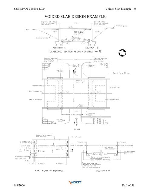
CONSPAN Version 4.0.0 <strong>Voided</strong> <strong>Slab</strong> <strong>Example</strong> 1.0<br />
VOIDED SLAB DESIGN EXAMPLE<br />
9/8/2006 Pg 1 of 58
CONSPAN Version 4.0.0 <strong>Voided</strong> <strong>Slab</strong> <strong>Example</strong> 1.0<br />
Concrete Properties<br />
Strength @ time of release:<br />
Strength @ 28 days:<br />
Unit weight:<br />
4000 psi<br />
5000 psi<br />
150 pcf<br />
Strand Properties:<br />
Strand type:<br />
7 / 16 ” diameter - low relaxation strands<br />
Ultimate strength: 270 ksi<br />
Modulus of Elasticity: 28,500 ksi<br />
Rebar Properties:<br />
Grade 60<br />
9/8/2006 Pg 2 of 58
CONSPAN Version 4.0.0 <strong>Voided</strong> <strong>Slab</strong> <strong>Example</strong> 1.0<br />
Start of <strong>Voided</strong> <strong>Slab</strong> Tutorial<br />
Open CONSPAN Program:<br />
Double Click on CONSPAN icon on Desktop<br />
OR<br />
Click on Start<br />
All Programs<br />
LEAP Software<br />
CONSPAN – AASHTO Standard & LRFD<br />
Before getting started on the example problem, click on the About icon at the top of the screen.<br />
Verify that the CONSPAN program is version 4.0.0, if not; this must be addressed before moving<br />
forward with the example problem.<br />
9/8/2006 Pg 3 of 58
CONSPAN Version 4.0.0 <strong>Voided</strong> <strong>Slab</strong> <strong>Example</strong> 1.0<br />
Screen 1: Project Screen<br />
Input the following in the appropriate fields:<br />
Project Name: <strong>Voided</strong> <strong>Slab</strong> <strong>Example</strong><br />
User Job Number: leave blank<br />
State: VA<br />
Date: the program will input the date<br />
- If the example program is revised at a later date, the revised date may be entered.<br />
(the program does not auto update)<br />
State Job Number: leave blank (may input state project # in this field for actual project)<br />
By: designer’s initials<br />
9/8/2006 Pg 4 of 58
CONSPAN Version 4.0.0 <strong>Voided</strong> <strong>Slab</strong> <strong>Example</strong> 1.0<br />
Screen 1: Project Screen (continued)<br />
<strong>Design</strong> Code: LRFD (program default)<br />
Units: U.S. Units (program default)<br />
- NOTE:<br />
o If SI Units (Metric) is selected, successive screens will display metric units.<br />
Span Type: Simple Span (program default)<br />
State Specification: None (program default)<br />
- Only other alternative is Florida, therefore select none at this time.<br />
9/8/2006 Pg 5 of 58
CONSPAN Version 4.0.0 <strong>Voided</strong> <strong>Slab</strong> <strong>Example</strong> 1.0<br />
Screen 2: Geometry Screen<br />
Input the following in the appropriate fields:<br />
Overall Width – 42 (ft )<br />
Skew Angle<br />
Start – 0 (deg)<br />
End – 0 (deg)<br />
Curb Data<br />
Left – 1.6667 (ft)<br />
Right – 1.6667 (ft)<br />
Topping Data<br />
Suppl. Thickness (not the sacrificial thickness) – 0 (in)<br />
Deck Thickness (effective) – 0 (in)<br />
NOTE:<br />
A sacrificial topping surface thickness is input later on the Loads Screen.<br />
Haunch Thickness – 0 (in)<br />
Haunch Width – 0 (in)<br />
9/8/2006 Pg 6 of 58
CONSPAN Version 4.0.0 <strong>Voided</strong> <strong>Slab</strong> <strong>Example</strong> 1.0<br />
Screen 2: Geometry Screen (continued)<br />
Lane Data<br />
Number and Width:<br />
These values are generated by the program <strong>using</strong> default lane width of 12 feet.<br />
(3.6 meter for metric)<br />
Simply verify lane with and the number of design lanes that are computed.<br />
Span Data<br />
Precast length – 42.5 (ft)<br />
Release Span – 42.5 (ft) (same as precast length)<br />
Bearing to Bearing – 41.5 (ft)<br />
View Beam Section Library:<br />
Click On OR Select Libraries<br />
Beam Sections…<br />
For this example – <strong>using</strong> Prestressed <strong>Voided</strong> <strong>Slab</strong> Span (3’-0” x 21”)<br />
- Highlight pcs21a and click on Modify tab to view the section properties.<br />
9/8/2006 Pg 7 of 58
CONSPAN Version 4.0.0 <strong>Voided</strong> <strong>Slab</strong> <strong>Example</strong> 1.0<br />
Hollow Core <strong>Slab</strong> Section screen should appear after clicking on Modify tab.<br />
The pcs21a voided slab section is already defined. This screen simply provides the geometry details<br />
and section properties of the selected pcs21a voided slab.<br />
The Template and Edit tabs can also be used to define the properties of the slab section.<br />
9/8/2006 Pg 8 of 58
CONSPAN Version 4.0.0 <strong>Voided</strong> <strong>Slab</strong> <strong>Example</strong> 1.0<br />
Click on Template tab to view the location and number of strands allowed in the section.<br />
To modify the strands, highlight those to be modified and change the height and/or number of strands<br />
at that location. Location and number of strands can also be deleted or added <strong>using</strong> the corresponding<br />
tabs. Once you are satisfied, click on Modify tab.<br />
If changes are made to the number of strands and/or location, click OK tab.<br />
NOTE: For this example, do not revise the stand arrangement, simply click Cancel tab.<br />
9/8/2006 Pg 9 of 58
CONSPAN Version 4.0.0 <strong>Voided</strong> <strong>Slab</strong> <strong>Example</strong> 1.0<br />
Click on Edit tab to view the slab section.<br />
Place pointer on the tabs to the left to view the different commands on this screen.<br />
<strong>Example</strong>: Return and update<br />
(click this, if revisions are made and are to be saved)<br />
NOTE: For this example, do not revise the voided slab section, simply click on the red X in the upper<br />
right hand corner of the Section Drawing Editor screen.<br />
9/8/2006 Pg 10 of 58
CONSPAN Version 4.0.0 <strong>Voided</strong> <strong>Slab</strong> <strong>Example</strong> 1.0<br />
After closing the Template screen (shown on pg. 9) and the Section Drawing Editor screen (shown on<br />
pg. 10), the Hollow Core <strong>Slab</strong> Section screen is still open.<br />
If changes were made in the Template screen, the Section Drawing Editor screen and/or the Hollow<br />
Core <strong>Slab</strong> Section screen and wish to be saved, click on the OK tab.<br />
NOTE: For this example, no revisions are to be made, simply click Cancel tab.<br />
9/8/2006 Pg 11 of 58
CONSPAN Version 4.0.0 <strong>Voided</strong> <strong>Slab</strong> <strong>Example</strong> 1.0<br />
After closing the Hollow Core <strong>Slab</strong> Section screen (shown on pg. 11), the Beam Section Library screen<br />
is still open.<br />
If changes were made to the voided slab section that was selected and wish to be saved, click on the<br />
Save tab.<br />
Click OK to save the changes made to the voided slab section.<br />
NOTE: For this example, no revisions are to be made, simply click Close tab.<br />
9/8/2006 Pg 12 of 58
CONSPAN Version 4.0.0 <strong>Voided</strong> <strong>Slab</strong> <strong>Example</strong> 1.0<br />
Screen 2: Geometry Screen (continued)<br />
Beam/Type Location<br />
Under Beam Type, select Rectangular Beam w/ Circular Voids<br />
Under Beam ID, select pcs21a<br />
Distance From Last Beam, ft<br />
- program reads this distance from left to right<br />
- Method 1 to input beam sections:<br />
o Beam No. 1 distance from last beam => 1.5 ft (this is distance from left edge<br />
of slab to center of beam 1), input and click Add tab<br />
o Beam No. 2 distance from last beam => 3 ft (this is distance from center of<br />
beam 1 to center of beam 2), input and click Add tab<br />
o Continue the same process until all 14 beams are entered.<br />
o Test the program by highlighting the 14 th beam and click Add button<br />
9/8/2006 Pg 13 of 58
CONSPAN Version 4.0.0 <strong>Voided</strong> <strong>Slab</strong> <strong>Example</strong> 1.0<br />
o Program does not allow this since it exceeds width previously defined<br />
- Method 2 to input beam sections:<br />
o Click on Generate… tab in lower right hand corner<br />
o Input number of beams<br />
• Quantity: 14<br />
o Input distance from left end of slab to center line of first beam<br />
• D: 1.5 ft<br />
o Click OK<br />
o Geometry screen should look the same as shown in screen shot on page 13.<br />
9/8/2006 Pg 14 of 58
CONSPAN Version 4.0.0 <strong>Voided</strong> <strong>Slab</strong> <strong>Example</strong> 1.0<br />
View Sketch of Transverse Section:<br />
Click On<br />
OR<br />
Select Show<br />
Image…<br />
This provides a visual representation of the voided slab deck section that you have just defined.<br />
PROGRAM NOTE:<br />
- To exit this page without exiting the program, click on the gray X in the upper<br />
right hand corner (NOT the red X)<br />
- Program does not auto-save. Now is a good time to save this example problem.<br />
(It would be a good idea to save the program after information has been input<br />
into each screen)<br />
9/8/2006 Pg 15 of 58
CONSPAN Version 4.0.0 <strong>Voided</strong> <strong>Slab</strong> <strong>Example</strong> 1.0<br />
Screen 3: Materials Screen<br />
Input the following in the appropriate fields:<br />
Concrete<br />
Girder Release<br />
Unit Weight – 150 pcf (program default)<br />
Strength – 4 ksi<br />
K1 – 1 (program default)<br />
Elasticity – computed by program<br />
Girder Final<br />
Unit Weight – 150 pcf (program default)<br />
Strength – 5 ksi<br />
K1 – 1 (program default)<br />
Elasticity – computed by program<br />
Deck<br />
Unit Weight – 150 pcf (program default)<br />
Strength – 4 ksi<br />
K1 – 1 (program default)<br />
Elasticity – computed by program<br />
Tendon Rebar<br />
Elasticity – 29000 ksi (program default)<br />
f y – 60 ksi (program default)<br />
9/8/2006 Pg 16 of 58
CONSPAN Version 4.0.0 <strong>Voided</strong> <strong>Slab</strong> <strong>Example</strong> 1.0<br />
PROGRAM NOTE:<br />
- The F1 key is the help function key<br />
- The program will provide online help whenever this key is selected<br />
- <strong>Example</strong> of program help function (F1 key):<br />
o What is K1?<br />
o While on the Materials screen, press F1 key<br />
o Click on Material Screen Terms<br />
9/8/2006 Pg 17 of 58
CONSPAN Version 4.0.0 <strong>Voided</strong> <strong>Slab</strong> <strong>Example</strong> 1.0<br />
o Provides description of K1 variable, and where this factor can be found in<br />
the AASHTO LRFD Specifications.<br />
o When finished with the Help screen, click on the red X in upper right corner<br />
of the CONSPAN v4.0.0. Online Help screen.<br />
9/8/2006 Pg 18 of 58
CONSPAN Version 4.0.0 <strong>Voided</strong> <strong>Slab</strong> <strong>Example</strong> 1.0<br />
View Prestressing Tendon Properties:<br />
Click On<br />
OR<br />
Select Libraries<br />
Prestressing Tendon…<br />
For this example – <strong>using</strong> 7 / 16 ” diameter low relaxation strands<br />
- Highlight the view the Tendon ID labeled 7 / 16 ”-207K-LL to view the strand<br />
properties<br />
- The prestressing stand properties can be modified and saved similar to what was<br />
described under the Beam Section properties part of the handout<br />
NOTE: For this example, no changes to the strand are to be made, simply click Close tab.<br />
9/8/2006 Pg 19 of 58
CONSPAN Version 4.0.0 <strong>Voided</strong> <strong>Slab</strong> <strong>Example</strong> 1.0<br />
Screen 3: Materials Screen (continued)<br />
Transformation of Steel<br />
Transform All Prestressing Tendons<br />
- Do not check this box for the example problem.<br />
- If selected, the program will transform all strands into an equivalent area of concrete<br />
and use it to calculate the section properties.<br />
Transform Rebars<br />
- Do not check this box for the example problem.<br />
- If selected, the program will transform the designated rebar area into an equivalent<br />
area of concrete and use it to calculate the section properties.<br />
Prestressing Tendon<br />
- Under Tendon ID, highlight 7/16-207K-LL<br />
Pattern<br />
- Check Straight for this exampleproblem.<br />
Debonded Length Increment, in<br />
- Program inputs default value as shown on screen shot, but since we are not<br />
considering debonded the stands this value does not affect the design<br />
- N/A<br />
Maximum Auto-Debonding Percentage<br />
- N/A (for similar reasons as stated above)<br />
9/8/2006 Pg 20 of 58
CONSPAN Version 4.0.0 <strong>Voided</strong> <strong>Slab</strong> <strong>Example</strong> 1.0<br />
Screen 4: Loads Screen<br />
Before Dead Loads values are input by hand, first open the Wizard Screen<br />
Wizard<br />
- Click on Wizard tab on the right edge of screen<br />
9/8/2006 Pg 21 of 58
CONSPAN Version 4.0.0 <strong>Voided</strong> <strong>Slab</strong> <strong>Example</strong> 1.0<br />
Input Load Values:<br />
Left Barrier Weight = 0.4455 klf<br />
Future Wearing Surface = 0.015 ksf<br />
Sacrificial Wearing Surface = 4.5 in<br />
o Thickness of overlay input here as discussed on pg. 6 of handout<br />
Right Barrier Weight = 0.4455 klf<br />
Stay-in-Place Deck Forms = 0.060 klf (Construction Tolerance)<br />
Dead Load:<br />
To see how the loads were calculated, refer to MATHCAD program<br />
o File Name: <strong>Voided</strong> <strong>Slab</strong> <strong>Design</strong> <strong>Example</strong>.mcd – pg 4<br />
o For simplicity, MATHCAD values are shown below<br />
W c := 0.150 ⋅ kcf<br />
Unit weight of concrete<br />
S g := 3.0 ⋅ ft<br />
Girder spacing<br />
W const := 20 ⋅ psf<br />
Construction tolerance<br />
wt jersey 0.110 yd 3<br />
:= ⋅<br />
Volume for F-shaped barrier<br />
ft<br />
(S & B Manual Vol. V - Part 5: PSS-3F)<br />
Weight of railing: w rail := wt jersey ⋅ W c<br />
w rail = 0.4455klf<br />
Future wearing surface: w fws := 0.015 ⋅ ksf<br />
Sacrificial wearing surface: t d := 2.0 ⋅ in<br />
Stay-in-Place deck forms: w const := W const ⋅ S g<br />
w const = 0.060klf<br />
9/8/2006 Pg 22 of 58
CONSPAN Version 4.0.0 <strong>Voided</strong> <strong>Slab</strong> <strong>Example</strong> 1.0<br />
Once the loads have been input into the Load Wizard, Click OK.<br />
The Loads Screen should now look similar to the screen below:<br />
9/8/2006 Pg 23 of 58
CONSPAN Version 4.0.0 <strong>Voided</strong> <strong>Slab</strong> <strong>Example</strong> 1.0<br />
PROGRAM NOTE:<br />
- It is important that the correct load information is entered into the wizard.<br />
- Once OK is clicked on the Load Wizard screen, the program calculates and<br />
distributes the loads to all the beams as seen on the previous page.<br />
- At this time, the loads that were input into the wizard are no longer shown.<br />
o Click on Wizard tab to verify that the input loads are no longer shown.<br />
o For this example, no changes to be made, click Cancel.<br />
- If the computed load values are to be changed after running the wizard, they<br />
can be changed manually on the Loads Screen or the desired loads can be<br />
deleted from the Loads Screen and the wizard can be run again.<br />
- If all of the loads shown on the Loads Screen are not deleted and the wizard is<br />
run again, then certain loads may be placed more than once onto the transverse<br />
section.<br />
- Therefore, it is important to check that none of the loads on the Loads Screen<br />
have been duplicated if the wizard is run more than once.<br />
9/8/2006 Pg 24 of 58
CONSPAN Version 4.0.0 <strong>Voided</strong> <strong>Slab</strong> <strong>Example</strong> 1.0<br />
View Live Load Library:<br />
Click On<br />
OR<br />
Select Libraries<br />
Live Load…<br />
For this example – designing for <strong>Design</strong> Lane, <strong>Design</strong> Tandem and <strong>Design</strong> Truck Live Loads<br />
- Highlight the Deign Lane type with <strong>Design</strong> Lane ID (since <strong>using</strong> English unit for<br />
this example) and click Modify… tab<br />
9/8/2006 Pg 25 of 58
CONSPAN Version 4.0.0 <strong>Voided</strong> <strong>Slab</strong> <strong>Example</strong> 1.0<br />
- The loads used for the design calculations can be viewed for the <strong>Design</strong> Lane Live<br />
Loads case.<br />
- There are no changes are to made to this load case, click Cancel.<br />
- The same process can be used to view the remaining Live Load cases shown in this<br />
library.<br />
NOTE: For this example, no changes are to be made to the live load cases, simply click Close tab.<br />
9/8/2006 Pg 26 of 58
CONSPAN Version 4.0.0 <strong>Voided</strong> <strong>Slab</strong> <strong>Example</strong> 1.0<br />
Screen 4: Loads Screen (continued)<br />
Diaphragm<br />
- There are no diaphragms for this example. Therefore, leave these fields blank.<br />
<strong>Design</strong> Live Load<br />
Include LL Deflection<br />
o According to the LRFD design code, if the user invokes the optional live<br />
load deflection criteria specified in LRFD Art. 2.5.2.6.2, the deflection<br />
should be taken as the larger of (a) the resulting deflection from the design<br />
truck alone, or (b) the resulting deflection from 25% of the design truck<br />
taken together with the design lane load. If this is selected, the above two<br />
conditions are checked and the deflection under the governing load is printed<br />
in the camber and deflections section of the printout.<br />
o Check box for this example.<br />
Include Pedestrian Load<br />
o No pedestrian load for this example.<br />
o If there is a pedestrian load, check the box and input the load (plf) in the<br />
indicated box to the right.<br />
Available & Selected<br />
- These tabs are for the types of vehicular Live Loading to be included in the voided<br />
slab design.<br />
- For this example, include:<br />
o <strong>Design</strong> Lane<br />
}<br />
o <strong>Design</strong> Tandem (Program default includes these)<br />
o <strong>Design</strong> Truck<br />
• Make sure that these LL cases under Selected do not show<br />
(=> not incl.)<br />
9/8/2006 Pg 27 of 58
CONSPAN Version 4.0.0 <strong>Voided</strong> <strong>Slab</strong> <strong>Example</strong> 1.0<br />
Screen 4: Loads Screen (continued)<br />
Available & Selected (continued)<br />
- <strong>Example</strong>s on how to include and/or remove Live Loading cases:<br />
o Include <strong>Design</strong> Lane load case:<br />
• Highlight <strong>Design</strong> Lane under Available<br />
• Click<br />
• Under Selected, <strong>Design</strong> Lane should not show (- not incl.)<br />
o Remove Double Truck load case:<br />
• Highlight Double Truck under Available<br />
• Click<br />
• Under Selected, Double Truck should show (- not incl.)<br />
o The screen should look similar to the one below<br />
9/8/2006 Pg 28 of 58
CONSPAN Version 4.0.0 <strong>Voided</strong> <strong>Slab</strong> <strong>Example</strong> 1.0<br />
Screen 5: Analysis Screen<br />
Click on Analysis Factors… tab<br />
9/8/2006 Pg 29 of 58
CONSPAN Version 4.0.0 <strong>Voided</strong> <strong>Slab</strong> <strong>Example</strong> 1.0<br />
Analysis Factors – Distribution Tab<br />
- Distribute Dead Load<br />
o Check, Based on Tributary Fraction<br />
o Composite loads are currently distributed <strong>using</strong> this method and until told<br />
otherwise, this method will continue to be used.<br />
- Dead Load<br />
o Program provides a computed distribution for DL equally to all beams<br />
- Dynamic Load Factor<br />
o Truck = 0.33 (program default)<br />
o Lane = 0 (program default)<br />
- Live Load – Girder<br />
o Program provides a computed distribution for LL shear and moment for 1<br />
lane and 2+ lanes<br />
o These computed values can be verified by hand or by viewing the<br />
MATHCAD program<br />
9/8/2006 Pg 30 of 58
CONSPAN Version 4.0.0 <strong>Voided</strong> <strong>Slab</strong> <strong>Example</strong> 1.0<br />
Analysis Factors – Load Factors Tab<br />
- Program defaults to the values listed above.<br />
- User can verify these values with AASHTO LRFD Specs.<br />
- For this example, these values will not be adjusted.<br />
- NOTE:<br />
o Strength II Limit State is not included since this deals with a permit vehicle<br />
under analysis, which is not under consideration in this example.<br />
9/8/2006 Pg 31 of 58
CONSPAN Version 4.0.0 <strong>Voided</strong> <strong>Slab</strong> <strong>Example</strong> 1.0<br />
Analysis Factors – Modifier Tab<br />
- Program defaults to the values listed above.<br />
- For more information on these factors, see AASHTO LRFD Spec., 1.3.2.<br />
- For this example, these values will not be adjusted.<br />
NOTE:<br />
- If changes have been made under Analysis Factors screen, it is important to click<br />
OK before exiting the screen or the changes will not be saved.<br />
Click on Project Parameters… tab<br />
9/8/2006 Pg 32 of 58
CONSPAN Version 4.0.0 <strong>Voided</strong> <strong>Slab</strong> <strong>Example</strong> 1.0<br />
Project Parameters – Limiting Stress Tab<br />
- Program defaults to the values listed above.<br />
- User can verify these values with AASHTO LRFD Specs.<br />
- Click Edit Factors… tab to view the calculated values.<br />
- For this example, these values will not be adjusted. Therefore, click Cancel.<br />
9/8/2006 Pg 33 of 58
CONSPAN Version 4.0.0 <strong>Voided</strong> <strong>Slab</strong> <strong>Example</strong> 1.0<br />
Project Parameters – Restraining Moments Tab<br />
- Program defaults to Full Continuity<br />
- Not applicable for simple span design of voided slab. Therefore, click the next tab<br />
labeled Multipliers.<br />
9/8/2006 Pg 34 of 58
CONSPAN Version 4.0.0 <strong>Voided</strong> <strong>Slab</strong> <strong>Example</strong> 1.0<br />
Project Parameters – Multipliers Tab<br />
- Program defaults to the values listed above.<br />
- Deflection Multipliers<br />
o As specified in the PCI <strong>Design</strong> Handbook (Fifth Edition), long-term<br />
deflections for a prestressed beam are obtained by multiplying short-term<br />
deflections with specified factors. CONSPAN follows this same approach.<br />
o Can refer to the PCI <strong>Design</strong> Handbook (Fifth Edition) for a list of such<br />
factors for different loads.<br />
- Length Multipliers<br />
o Bonded: Transfer<br />
• Program default is 1.0.<br />
o Bonded: Development<br />
• In the LRFD mode, as well as in the Standard Specifications mode,<br />
this factor has been set to 1.6.<br />
o Debonded:<br />
• N/A<br />
- No changes are to be made. Therefore, click the next tab labeled Resistance<br />
Factor/Losses.<br />
9/8/2006 Pg 35 of 58
CONSPAN Version 4.0.0 <strong>Voided</strong> <strong>Slab</strong> <strong>Example</strong> 1.0<br />
Project Parameters – Resistance Factor/Losses Tab<br />
- Program defaults to the values listed above.<br />
- Resistance Factor<br />
o The default resistance values shown are as specified in LRFD Art. 5.5.4.2<br />
and LFD Art 9.14.<br />
o More information can be found by <strong>using</strong> the Help Function (press F1)<br />
- Prestress Losses<br />
o There are two methods to calculate the prestress losses:<br />
• The AASHTO method is as specified in LRFD article 5.9.5. (<strong>using</strong><br />
5.9.5.3. Approximate Estimate of Time Dependent Losses).<br />
• The Manual method allows the user to specify the loss percentages at<br />
release and final.<br />
- Compute Losses <strong>using</strong><br />
o Select the approximate method to compute losses according to the provisions<br />
of LRFD Art. 5.9.5.3 Approximate Estimate of Time Dependent Losses.<br />
- No changes are to be made. Therefore, click the next tab labeled Moment and Shear<br />
Provisions.<br />
9/8/2006 Pg 36 of 58
CONSPAN Version 4.0.0 <strong>Voided</strong> <strong>Slab</strong> <strong>Example</strong> 1.0<br />
Project Parameters – Moment and Shear Provisions Tab<br />
- Program defaults to the values listed above.<br />
- Program default set to:<br />
o Moment Method<br />
• AASHTO<br />
o Horizontal Shear Method<br />
• Include Beam and <strong>Slab</strong> Contribution in Vu<br />
- For more information on the Moment and Shear Provisions tab, use the program<br />
Help Function. (press F1 key)<br />
- No changes are to be made.<br />
Since no changes were made under the Project Parameters screen for this example problem, click<br />
Cancel.<br />
9/8/2006 Pg 37 of 58
CONSPAN Version 4.0.0 <strong>Voided</strong> <strong>Slab</strong> <strong>Example</strong> 1.0<br />
Screen 5: Analysis Screen (continued)<br />
Click on Run Analysis… tab<br />
User screen should look similar to screen shot below.<br />
Toolbar at top of screen allows user to view certain desired output:<br />
9/8/2006 Pg 38 of 58
CONSPAN Version 4.0.0 <strong>Voided</strong> <strong>Slab</strong> <strong>Example</strong> 1.0<br />
Screen 6: Beam Screen<br />
For this example, the strand arrangement will be designed for an interior slab section.<br />
Place the pointer on Beam 2 and single click. This should highlight Beam 2 in red (should look like<br />
the screen above).<br />
Before a strand pattern is designed for an interior beam, click on the Edit… tab on the left hand side of<br />
the Beam Screen.<br />
9/8/2006 Pg 39 of 58
CONSPAN Version 4.0.0 <strong>Voided</strong> <strong>Slab</strong> <strong>Example</strong> 1.0<br />
<strong>Design</strong> Parameters – Effective Width Tab<br />
- Verify that the effective width calculated by program is accurate.<br />
- Effective width for this example should be 36 in. If so, click Cancel (no need to<br />
change).<br />
Notice that there are other tabs included under the <strong>Design</strong> Parameters which have already been<br />
addressed:<br />
<strong>Design</strong> Parameters – Limiting Stress Tab<br />
- Under Project Parameters – Limiting Stress (see pg. 33 of handout)<br />
<strong>Design</strong> Parameters – Prestressing Tendon Tab<br />
- On Materials Screen (see pg. 20 of handout)<br />
<strong>Design</strong> Parameters – Prestress Losses Tab<br />
- Under Project Parameters - Resistance Factor/Losses Tab (see pg. 36 of handout)<br />
<strong>Design</strong> Parameters – Transform Steel Tab<br />
- On Materials Screen (see pg. 20 of handout)<br />
9/8/2006 Pg 40 of 58
CONSPAN Version 4.0.0 <strong>Voided</strong> <strong>Slab</strong> <strong>Example</strong> 1.0<br />
Screen 6: Beam Screen (continued)<br />
Now, design a strand pattern for interior Beam 2<br />
Single click on Strand Pattern… tab.<br />
Unless the user knows what strand pattern to analyze, single click on the Auto <strong>Design</strong> tab and the<br />
program will provide a strand arrangement.<br />
9/8/2006 Pg 41 of 58
CONSPAN Version 4.0.0 <strong>Voided</strong> <strong>Slab</strong> <strong>Example</strong> 1.0<br />
The program will automatically provide a screen titled <strong>Design</strong> Status.<br />
This screen provides the stresses computed by the program at release and final conditions as well as<br />
the moments at both strength and service limit states.<br />
If a stress failure has occurred, the program will highlight that value in red.<br />
At this point, click the Close tab.<br />
9/8/2006 Pg 42 of 58
CONSPAN Version 4.0.0 <strong>Voided</strong> <strong>Slab</strong> <strong>Example</strong> 1.0<br />
The program indicates that 14 straight strands are adequate for Beam 2 design.<br />
PROGRAM NOTE:<br />
- If Reset Pattern is selected, the strand pattern currently shown on the screen<br />
will be erased.<br />
- If a strand pattern is input by hand and Auto <strong>Design</strong> is selected, it will ERASE<br />
the previous strand pattern and provide a new strand pattern.<br />
o <strong>Example</strong> on how to avoid this:<br />
• Select Beam 2 and select Auto <strong>Design</strong> to see what strand pattern<br />
the program provides, click OK.<br />
• Next, select Beam 3 and input a strand pattern to analyze, click<br />
<strong>Design</strong> Status to view if it passes. If satisfied, click OK.<br />
• This should prevent the accidental overriding of the previous<br />
input.<br />
At this time, click OK for this example problem.<br />
9/8/2006 Pg 43 of 58
CONSPAN Version 4.0.0 <strong>Voided</strong> <strong>Slab</strong> <strong>Example</strong> 1.0<br />
The beam screen should now look similar to the screen below.<br />
At the bottom of the screen the location of the 14 tendons previously designed for Beam 2 are shown<br />
in the transverse beam sections at mid-span and at the end of the beam.<br />
Above the transverse section sketches, the location of the tendons as well as the precast and bearing to<br />
bearing beam lengths is provided in the longitudinal beam sketch.<br />
9/8/2006 Pg 44 of 58
CONSPAN Version 4.0.0 <strong>Voided</strong> <strong>Slab</strong> <strong>Example</strong> 1.0<br />
How to input strands by hand (For future reference, NOT for this example):<br />
Type:<br />
End:<br />
Straight or Draped<br />
NOTE: On Materials screen straight strands were selected. Therefore, straight is the only<br />
option for this example.<br />
The distance provided is from the bottom of slab.<br />
NOTE: Strand location previously defined (Tendon Icon)<br />
# of Strands (max available)<br />
Input number of stands at defined location.<br />
NOTE: Maximum number of strands previously defined (Tendon Icon)<br />
Add<br />
After the strands are defined, click Add tab.<br />
Modify<br />
Highlight row of existing stands to be modified.<br />
Make changes to location and/or number of strands and click Modify tab.<br />
Delete<br />
Highlight row of stands to be removed and click Delete tab<br />
Copy to…<br />
Option to copy strand pattern to any of the other beams or all beams<br />
If Copy to… is selected and a strand pattern is not to be copied, click Cancel tab to exit.<br />
9/8/2006 Pg 45 of 58
CONSPAN Version 4.0.0 <strong>Voided</strong> <strong>Slab</strong> <strong>Example</strong> 1.0<br />
View Rebar Library:<br />
Click On<br />
OR<br />
Selection Libraries<br />
Rebar…<br />
For this example – <strong>using</strong> #3 bars designated as US#4(M13)<br />
- The rebar properties can be viewed from this screen and modified and saved similar<br />
to what was described under the Beam Section properties part of the handout.<br />
NOTE: For this example, no changes to the reinforcement are to be made, simply click Close tab.<br />
9/8/2006 Pg 46 of 58
CONSPAN Version 4.0.0 <strong>Voided</strong> <strong>Slab</strong> <strong>Example</strong> 1.0<br />
Screen 6: Beam Screen (continued)<br />
Now that a strand pattern design has been performed for interior Beam 2, design the shear<br />
reinforcement for the same interior beam.<br />
Single click on Rebar Pattern… tab.<br />
9/8/2006 Pg 47 of 58
CONSPAN Version 4.0.0 <strong>Voided</strong> <strong>Slab</strong> <strong>Example</strong> 1.0<br />
First, refer to the Auto <strong>Design</strong> on left hand side of screen.<br />
Auto <strong>Design</strong><br />
Stirrup Increment: in<br />
- Enter 6.0 (Program default is 6.0)<br />
Size:<br />
- Select US#4(M13) (Program default is US#3(M10))<br />
Legs:<br />
- Enter 2 (Program default is 2)<br />
Unless the user knows what shear reinforcement pattern to analyze, single click on the Auto <strong>Design</strong>…<br />
tab and the program will shear reinforcement required for the example problem based on the<br />
information defined above. (similar to the deign of the Strand Pattern)<br />
Click Auto-<strong>Design</strong>… tab<br />
The message above appears whether or not shear reinforcement has been previously defined.<br />
Since shear reinforcement has not been defined for Beam 2, click OK.<br />
9/8/2006 Pg 48 of 58
CONSPAN Version 4.0.0 <strong>Voided</strong> <strong>Slab</strong> <strong>Example</strong> 1.0<br />
The program provides the following stirrup spacing for Beam 2.<br />
Notice at the top of the Rebar Pattern screen, there is a Neg. Moment Continuity Steel tab.<br />
Click on this tab.<br />
Program recognizes that this does not apply to our simple span example.<br />
Click OK to exit.<br />
Click OK at the bottom of Rebar Pattern screen.<br />
9/8/2006 Pg 49 of 58
CONSPAN Version 4.0.0 <strong>Voided</strong> <strong>Slab</strong> <strong>Example</strong> 1.0<br />
Screen 6: Beam Screen (continued)<br />
The shear reinforcement designed by the program is placed on the sketch of the longitudinal section of<br />
the beam.<br />
9/8/2006 Pg 50 of 58
CONSPAN Version 4.0.0 <strong>Voided</strong> <strong>Slab</strong> <strong>Example</strong> 1.0<br />
How to input shear reinforcement by hand (For future reference, NOT for this example):<br />
Number of Legs:<br />
Defined number of stirrup legs to be placed.<br />
Once this is defined, the screen should appear similar the one below.<br />
Stirrup Size:<br />
Select stirrup size from the pull-down menu.<br />
NOTE: Stirrup sizes previously defined (Stirrup Icon)<br />
Stirrup Area (in^2):<br />
Program will input this value.<br />
NOTE: Stirrup area previously defined (Stirrup Icon)<br />
Stirrup Spacing (in):<br />
Enter desired spacing.<br />
Start:<br />
Enter the starting location of the defined stirrup size and spacing.<br />
End:<br />
Enter the ending location of the defined stirrup size and spacing.<br />
Once these fielded have been entered, click Insert…<br />
Continue the same process until shear reinforcement is defined for the entire precast beam length.<br />
9/8/2006 Pg 51 of 58
CONSPAN Version 4.0.0 <strong>Voided</strong> <strong>Slab</strong> <strong>Example</strong> 1.0<br />
Stirrups<br />
Insert…<br />
Copy…<br />
Delete…<br />
Copy to…<br />
}<br />
(These commands are similar to the ones<br />
discussed on the Strand Pattern screen)<br />
Graphs…<br />
- Click on Graphs… tab<br />
- Program provides a diagram of the area or steel required curve (in green).<br />
- When reinforcement has been defined, either by the user or the program, the<br />
diagram will show an area of steel provided curve (in red).<br />
- This provides a graphic check for the user whether enough steel has been provided<br />
or not.<br />
- To exit this screen, click on the red X in the upper right hand corner.<br />
9/8/2006 Pg 52 of 58
CONSPAN Version 4.0.0 <strong>Voided</strong> <strong>Slab</strong> <strong>Example</strong> 1.0<br />
Stirrups<br />
Symmetrical <strong>Design</strong><br />
- If stirrups have been defined for the first half of the beam, this command can be<br />
used if same reinforcement is to be mirrored about the center of the beam.<br />
- Click on Make Symmetrical tab.<br />
- If symmetrical stirrup design is desired, click Yes.<br />
9/8/2006 Pg 53 of 58
CONSPAN Version 4.0.0 <strong>Voided</strong> <strong>Slab</strong> <strong>Example</strong> 1.0<br />
View Results:<br />
Program provides a number of different ways to view design results:<br />
1. Results on Analysis screen (described on pg. 38 of handout)<br />
2. Results on Beams Screen, <strong>Design</strong> Status tab (described on pg. 42 of handout)<br />
3. After defining stand pattern for Beam 2 on this example, on Beam Screen click Results tab<br />
on left side of screen<br />
9/8/2006 Pg 54 of 58
CONSPAN Version 4.0.0 <strong>Voided</strong> <strong>Slab</strong> <strong>Example</strong> 1.0<br />
Destination<br />
- To view the output after the initial run, make sure it is set to Screen because there<br />
are approximately 30+ pages of output for each beam in this example problem. This<br />
should prevent wasting paper by accidentally sending it to the printer.<br />
- Can also set it to File and save it as a .txt document. This allows the user to view<br />
the results in the future without opening the CONSPAN program again.<br />
- For this example, set it to Screen.<br />
Project<br />
Geometry<br />
- Provides information as seen on Geometry Screen (located at top of output screen).<br />
- For this example, do not check.<br />
Loads<br />
- Provides information as seen on Loads Screen (located at top of output screen).<br />
- For this example, do not check.<br />
9/8/2006 Pg 55 of 58
CONSPAN Version 4.0.0 <strong>Voided</strong> <strong>Slab</strong> <strong>Example</strong> 1.0<br />
Library<br />
- Provides vehicular live loads selected for design on Loads Screen (located at bottom<br />
of output screen).<br />
- For this example, do not check.<br />
Beam Specific<br />
- Make sure Beam 2 is selected since this is the beam to be analyzed.<br />
<strong>Design</strong><br />
- If only certain design calculations are to be viewed, simply check the corresponding<br />
box or boxes and select Print/View.<br />
- For this example, check All.<br />
Rating<br />
- Check the corresponding live load box or boxes to be viewed and select Print/View.<br />
- Does not apply to this example.<br />
Click Print/View at bottom of screen<br />
Scroll through the design output to view the desired results.<br />
To exit this screen, click on red X in upper right hand corner.<br />
9/8/2006 Pg 56 of 58
CONSPAN Version 4.0.0 <strong>Voided</strong> <strong>Slab</strong> <strong>Example</strong> 1.0<br />
4. View results by either of the following:<br />
Click On OR Select Show<br />
Results…<br />
To exit this screen, click on grey X (NOT red X) in upper right hand corner.<br />
9/8/2006 Pg 57 of 58
CONSPAN Version 4.0.0 <strong>Voided</strong> <strong>Slab</strong> <strong>Example</strong> 1.0<br />
5. View graphic results by either of the following:<br />
Click On OR Select Show<br />
Diagrams…<br />
To exit this screen, click on red X in upper right hand corner.<br />
9/8/2006 Pg 58 of 58