Pressure resistance mechanism of reaction-type liquid gaskets (Part 2)
Pressure resistance mechanism of reaction-type liquid gaskets (Part 2)
Pressure resistance mechanism of reaction-type liquid gaskets (Part 2)

You also want an ePaper? Increase the reach of your titles
YUMPU automatically turns print PDFs into web optimized ePapers that Google loves.
Three Bond Technical News<br />
Issued July 1, 1982<br />
2<br />
<strong>Pressure</strong> <strong>resistance</strong> <strong>mechanism</strong> <strong>of</strong> <strong>reaction</strong>-<strong>type</strong> <strong>liquid</strong> <strong>gaskets</strong><br />
(<strong>Part</strong> 2)<br />
6. Basis <strong>of</strong> evaluation method and<br />
practical performance<br />
6-1. Factors that determine practical sealing<br />
performance<br />
For solid <strong>gaskets</strong> used in general mechanical<br />
components, the following factors are considered during<br />
component design to determine the appropriate bolt<br />
tightening force:<br />
(1) Tightening force required for solid <strong>gaskets</strong> (gasket<br />
factor and minimum tightening force)<br />
(2) Elongation <strong>of</strong> bolts by heat<br />
(3) Vibration and mechanical stress<br />
(4) Rigidity <strong>of</strong> the component.<br />
Total tightening force with bolts usually grows quite<br />
large, and no opening <strong>of</strong> the flange due to fluid pressure<br />
can occur, since the limition <strong>of</strong> joint pressure exceeds the<br />
internal fluid pressure.<br />
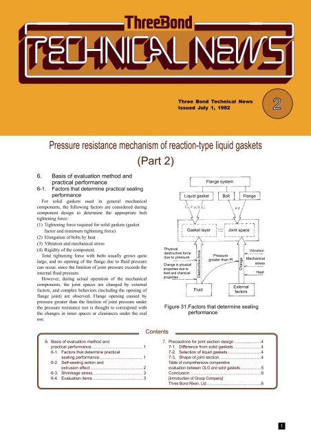
However, during actual operation <strong>of</strong> the mechanical<br />
components, the joint spaces are changed by external<br />
factors, and complex behaviors (including the opening <strong>of</strong><br />
flange joint) are observed. Flange opening caused by<br />
pressure greater than the limition <strong>of</strong> joint pressure under<br />
the pressure <strong>resistance</strong> test is thought to correspond with<br />
the changes in inner spaces or clearances under the real<br />
use.<br />
Physical<br />
destructive force<br />
due to pressure<br />
Change in physical<br />
properties due to<br />
heat and chemical<br />
properties<br />
Flange system<br />
Liquid gasket Bolt Flange<br />
Gasket layer<br />
Destructive force<br />
Fluid<br />
<strong>Pressure</strong><br />
greater than Pl<br />
Joint space<br />
Change<br />
External<br />
factors<br />
Vibration<br />
Mechanical<br />
stress<br />
Figure 31. Factors that determine sealing<br />
performance<br />
Heat<br />
Contents<br />
6. Basis <strong>of</strong> evaluation method and<br />
practical performance............................................ 1<br />
6-1. Factors that determine practical<br />
sealing performance..................................... 1<br />
6-2. Self-sealing action and<br />
extrusion effect ............................................. 2<br />
6-3. Shrinkage stress........................................... 3<br />
6-4. Evaluation items ........................................... 3<br />
7. Precautions for joint section design .......................4<br />
7-1. Difference from solid <strong>gaskets</strong>........................4<br />
7-2. Selection <strong>of</strong> <strong>liquid</strong> <strong>gaskets</strong>.............................4<br />
7-3. Shape <strong>of</strong> joint section....................................4<br />
Table <strong>of</strong> comprehensive comparative<br />
evaluation between OLG and solid <strong>gaskets</strong>..................5<br />
Conclusion .............................................................6<br />
[Introduction <strong>of</strong> Group Company]<br />
Three Bond Riken, Ltd...............................................6<br />
1
The material failure equation represents the<br />
relationship between the physical destructive force<br />
due to fluid pressure in use and the properties <strong>of</strong><br />
<strong>liquid</strong> <strong>gaskets</strong>. Therefore, the effects <strong>of</strong> heat and the<br />
chemical properties <strong>of</strong> the fluid must be considered<br />
as variables that affect adhesive force and cohesive<br />
force (including elastic modulus and tensile<br />
strength).<br />
state (a) is quickly reached, force Psinθ (which<br />
remains below destructive levels) given by the<br />
material failure equation is generated. As pressure<br />
increases, destruction states (b) and (c) are initiated,<br />
followed by state (d), initiating self-sealing.<br />
6-2. Self-sealing action and extrusion effect<br />
Solid <strong>gaskets</strong> require large contact surface<br />
pressure due to their pressure <strong>resistance</strong> <strong>mechanism</strong>,<br />
and leakage will occur if fluid pressure exceeds<br />
contact surface pressure. In the case <strong>of</strong> O-rings, the<br />
contact surface pressure deriving from assembly is<br />
not so large and the pressure is maximum at the<br />
center as shown in Figure 32-a. However, when<br />
fluid pressure is applied, the pressure is added to the<br />
original contact surface pressure, as shown in<br />
Figure 32-b, resulting in larger contact surface<br />
pressure because the O-ring is confined in the<br />
groove. This means that the maximum value <strong>of</strong><br />
contact surface pressure is Pm, which is larger than<br />
the value <strong>of</strong> fluid pressure P1, and no leakage<br />
occurs. The remarkably useful sealing action, in<br />
which fluid pressure is added to the contact surface<br />
pressure, is called self-sealing action.<br />
Figure 33. Self-sealing action <strong>of</strong> high modulus<br />
<strong>liquid</strong> <strong>gaskets</strong><br />
Assembly force kg<br />
Gap<br />
Immediately after coating P=0<br />
Compressed area<br />
Outside<br />
Liquid<br />
pressure P 1<br />
(a) O-ring (No fluid pressure is applied.)<br />
(b) Condition that prevents leakage from O-ring<br />
Figure 32. Distribution <strong>of</strong> contact surface<br />
pressure for O-ring<br />
In cases in which <strong>reaction</strong>-<strong>type</strong> <strong>liquid</strong> <strong>gaskets</strong><br />
may be destroyed, such a self-sealing <strong>mechanism</strong> is<br />
expected to function in the case <strong>of</strong> elastic materials.<br />
In Figure 33, when fluid pressure is applied and<br />
Figure 34. Extrusion effect <strong>of</strong> <strong>liquid</strong> <strong>gaskets</strong><br />
Although most <strong>liquid</strong> <strong>gaskets</strong> will exhibit<br />
extrusion in general use, the extrusion generated by<br />
high modulus <strong>liquid</strong> <strong>gaskets</strong> results in self-sealing<br />
action, as shown in Figure 34. Table 6 shows the<br />
results <strong>of</strong> tests on Three Bond 1215.<br />
Table 6. Extrusion effects associated with TB<br />
1215<br />
Testing condition Leakage pressure (kg/cm 2 )<br />
Average surface<br />
pressure kg/cm 2<br />
When pressure is<br />
applied.<br />
Pl value<br />
kg/cm 2<br />
With<br />
extrusion<br />
Extrusion is<br />
removed.<br />
50 22.5 68 53<br />
20 7.5 55 33<br />
* The test flange shown in Figure 6 was used.<br />
2
6-3. Shrinkage stress<br />
In solvent-<strong>type</strong> <strong>liquid</strong> <strong>gaskets</strong>, volume decreases<br />
when the solvent volatilizes. In <strong>reaction</strong>-<strong>type</strong> <strong>liquid</strong><br />
<strong>gaskets</strong>, shrinkage will occur when polymerization<br />
or condensation <strong>reaction</strong> takes place and<br />
intermolecular distance decreases. Due to such<br />
shrinkage <strong>of</strong> <strong>liquid</strong> <strong>gaskets</strong>, shear stress acts upon<br />
the gasket layer. If the shear stress exceeds the<br />
adhesive force during the curing process, the joint<br />
surface and gasket will separate, even if no external<br />
force is applied.<br />
Figure 35. Shear stress in gasket layer<br />
Assuming that the coefficient <strong>of</strong> linear<br />
contraction is C, Young's modulus is E, and the<br />
length <strong>of</strong> joint section is , average shrinkage stress<br />
P=E C acts in parallel to the joint surface.<br />
Furthermore, at the both ends <strong>of</strong> gasket layer and<br />
gaps <strong>of</strong> boundary surface, the stress distribution<br />
becomes non-uniform causing stress concentration.<br />
Since the results <strong>of</strong> adhesive strength tests<br />
incorporate such internal stresses, no additional<br />
steps to take this phenomenon into account are<br />
required.<br />
6-4. Evaluation items<br />
1) Evaluation items for sealing performance<br />
In conventional sealing performance tests,<br />
leakage pressure is measured by the pressure<br />
<strong>resistance</strong> test. However, this method<br />
simultaneously tests both the physical properties <strong>of</strong><br />
the flange system and gasket, and evaluation results<br />
can vary significantly, depending on flange system<br />
conditions.<br />
The sealing performance <strong>of</strong> <strong>liquid</strong> <strong>gaskets</strong> must<br />
be evaluated based on results obtained from tests on<br />
material properties corresponding to each term <strong>of</strong><br />
the material failure equation. Table 7 gives the<br />
physical properties to be evaluated.<br />
Table 7. Evaluation items for sealing<br />
performance<br />
Basic<br />
properties<br />
Conventional<br />
evaluation<br />
<strong>Pressure</strong><br />
<strong>resistance</strong> test<br />
Physical<br />
property<br />
evaluation<br />
Viscosity<br />
before<br />
curing<br />
Remarks<br />
Viscosity is one <strong>of</strong> the<br />
evaluation items for<br />
sealing performance<br />
because the performance<br />
<strong>of</strong> <strong>reaction</strong>-<strong>type</strong> gasket<br />
before curing is evaluated<br />
by assuming the gasket<br />
to be a non-drying<br />
material. (Measurement<br />
using a pressure-<strong>type</strong><br />
apparent viscosity meter<br />
is more feasible than<br />
measurement with a<br />
rotating viscosity meter.)<br />
Resistance<br />
to <strong>liquid</strong><br />
Weight<br />
change due to<br />
immersion<br />
Elongation<br />
Hardness<br />
Tensile<br />
strength<br />
Shear or<br />
tensile<br />
adhesive<br />
strength<br />
Changes in<br />
physical<br />
properties<br />
after<br />
immersion<br />
Determination <strong>of</strong> limit<br />
value <strong>of</strong> ∆h.<br />
Since θ varies depending<br />
on the conditions <strong>of</strong> the<br />
joint section space, it<br />
must be estimated from<br />
hardness or E.<br />
When the length <strong>of</strong><br />
gasket layer (width <strong>of</strong> the<br />
flange) is sufficiently long<br />
relative to thickness (not<br />
shorter than A1-A4<br />
shown in Figure 21), θ <strong>of</strong><br />
the used gasket is given<br />
by ∆h/h and P, and can<br />
be measured.<br />
For the determination <strong>of</strong><br />
Fs. However,<br />
measurement <strong>of</strong> tensile<br />
strength must also<br />
account for testing speed.<br />
Since the true value <strong>of</strong> Fa<br />
cannot be measured,<br />
common adhesive<br />
strength is measured<br />
instead.<br />
Changes in E and Fa are<br />
observed.<br />
2) Items for comprehensive evaluation<br />
In actual use, the time required to develop gasket<br />
sealing performance (curing rate) becomes an issue,<br />
and the durability <strong>of</strong> a gasket relative to the life <strong>of</strong><br />
the corresponding mechanical component is another<br />
major evaluation item. Aspects such as workability,<br />
cost-effectiveness, and handling qualities must also<br />
be evaluated.<br />
Table 8 provides a comprehensive list <strong>of</strong><br />
evaluation items. The importance <strong>of</strong> each item is<br />
determined by the user, location <strong>of</strong> use, and<br />
operating conditions.<br />
Table 8. Comprehensive evaluation <strong>of</strong><br />
<strong>reaction</strong>-<strong>type</strong> <strong>gaskets</strong><br />
Sealing performance<br />
Costeffectiveness<br />
Workability<br />
Management<br />
Basic<br />
properties<br />
Resistance to<br />
<strong>liquid</strong><br />
Low-temperatu<br />
re and<br />
high-temperat<br />
ure <strong>resistance</strong><br />
Developing<br />
time (curing<br />
rate)<br />
When coating<br />
When<br />
separating<br />
Cost<br />
Total cost<br />
Safety<br />
Storage<br />
stability<br />
According to Table Long-term<br />
7.<br />
evaluations<br />
According to Table based on<br />
7.<br />
service<br />
Should be<br />
conditions are<br />
evaluated together required.<br />
with <strong>resistance</strong> to<br />
<strong>liquid</strong>.<br />
The time required to develop sealing<br />
performance under service conditions<br />
(variation <strong>of</strong> viscosity over time from start to<br />
end <strong>of</strong> curing)<br />
For assembly lines, workability is evaluated<br />
together with the performance <strong>of</strong> coating<br />
equipment.<br />
Although workability depends on adhesive<br />
strength and elasticity, it is actually<br />
evaluated by manipulation.<br />
Unit price <strong>of</strong> the product<br />
Durability<br />
The various pros and cons <strong>of</strong> sealing<br />
performance, workability, handling quality<br />
and merits on designing are considered.<br />
In consideration <strong>of</strong> "Occupational Health<br />
and Safety Law" and "Fire Defense Law."<br />
Stability <strong>of</strong> material quality and safety in<br />
storage<br />
3
7. Precautions for joint section design<br />
The design <strong>of</strong> a flange system must take into<br />
account the interrelationships between operating<br />
conditions and physical properties <strong>of</strong> the <strong>liquid</strong><br />
gasket, the total tightening force <strong>of</strong> the bolts, flange<br />
shape, and external factors. (See Figure 31.)<br />
7-1. Difference from solid <strong>gaskets</strong><br />
1) Bolt tightening force and external factors<br />
The bolt tightening force determines the initial<br />
thickness <strong>of</strong> the gasket and affects the extent <strong>of</strong><br />
change in the joint section space in relation to<br />
external factors. Since the <strong>liquid</strong> gasket layer<br />
elastically follows changes in the joint section space,<br />
the large initial surface pressure required in the case<br />
<strong>of</strong> solid <strong>gaskets</strong> is not necessary.<br />
To identify the appropriate diameter, number, and<br />
initial tightening force <strong>of</strong> bolts, it is sufficient to<br />
consider the force required to hold the component<br />
so long as the displacement <strong>of</strong> both flange faces<br />
does not cause deformation exceeding the elastic<br />
limit <strong>of</strong> the gasket material.<br />
Table 9 shows the results obtained from a test <strong>of</strong> a<br />
flange system using <strong>reaction</strong>-<strong>type</strong> <strong>liquid</strong> <strong>gaskets</strong> in<br />
which bolts are removed when measuring the<br />
leakage pressure.<br />
Table 9. Leakage pressure <strong>of</strong> a flange measured<br />
without fixing bolts (kg/cm 2 )<br />
Type <strong>of</strong> gasket TB 1215<br />
Low-modulus<strong>type</strong><br />
silicone<br />
Anaerobic<br />
flexible <strong>type</strong><br />
Surface pressure at<br />
coating: 50 kg/cm 2 3.0 0.2 11<br />
Surface pressure at<br />
coating: 20 kg/cm 2 3.0 0.3 16<br />
Clearance: 100 µ 3.0 0.3 16<br />
2) Extent <strong>of</strong> joint surface finishing<br />
Solid <strong>gaskets</strong> require meticulous attention to the<br />
finish <strong>of</strong> joint surfaces.<br />
Spiral finishing marks and parallel streaks<br />
resulting from shaping or planing impair the<br />
performance <strong>of</strong> metal <strong>gaskets</strong>. Table 10 shows the<br />
extent <strong>of</strong> finishing required for solid <strong>gaskets</strong>.<br />
Table 10. Extent <strong>of</strong> finishing required for flange<br />
joint surface (solid <strong>gaskets</strong>)<br />
Gasket material<br />
Extent <strong>of</strong> finishing (S)<br />
Leather gasket 50 - 100<br />
Paper gasket 50 - 100<br />
Rubber gasket 50 - 100<br />
Compressed asbestos sheet 25<br />
Semi-metallic gasket 6.4 - 35<br />
Metal gasket 3.2 - 6.4<br />
Liquid <strong>gaskets</strong> require no such consideration due<br />
to their conforming ability. The only factors that<br />
need to be considered are those that affect the<br />
adhesiveness <strong>of</strong> the joint surface, such as oil stains.<br />
If the <strong>liquid</strong> gasket has adhesive strength<br />
corresponding to the elasticity <strong>of</strong> the material, it is<br />
possible to use a flange face that has not been<br />
machine-finished.<br />
3) Flange surface width<br />
Although the minimum width required for solid<br />
<strong>gaskets</strong> depends on the gasket thickness and<br />
material, solid <strong>gaskets</strong> are generally said to be a<br />
minimum <strong>of</strong> 5 mm. In the case <strong>of</strong> <strong>liquid</strong> <strong>gaskets</strong>, the<br />
length <strong>of</strong> the gasket (flange width) is adequate if it<br />
is greater than the distance available to relieve the<br />
compressive force exerted by <strong>liquid</strong> pressure (not<br />
less than A1 - A4 in Figure 21). Tests for OLG show<br />
that 3 mm is sufficient. (See Figure 11.)<br />
7-2. Selection <strong>of</strong> <strong>liquid</strong> <strong>gaskets</strong><br />
For flange systems for which conditions are<br />
known, the limit pressure <strong>resistance</strong> obtained by<br />
applying the physical properties <strong>of</strong> the <strong>liquid</strong> gasket<br />
to the material failure equation must exceed fluid<br />
pressure. In fact, <strong>reaction</strong>-<strong>type</strong> <strong>gaskets</strong> that have<br />
been completely cured may be used in virtually all<br />
cases in which no dynamic conditions (such as<br />
opening <strong>of</strong> the joint section) exist.<br />
When the evaluation must consider dynamic<br />
conditions, the limit pressure <strong>resistance</strong> can be<br />
determined by obtaining the maximum value <strong>of</strong> the<br />
opening <strong>of</strong> the flange caused by beating or<br />
mechanical stress due to vibration, and substituting<br />
it for ∆h (equation in 4.18) in the material failure<br />
equation. However, since the pressure <strong>resistance</strong> <strong>of</strong><br />
high-elasticity materials varies significantly with<br />
the value <strong>of</strong> θ, the relationship between pressure<br />
and θ must be considered (particularly relating to<br />
∆h).<br />
7-3. Shape <strong>of</strong> joint section<br />
Reaction-<strong>type</strong> <strong>liquid</strong> <strong>gaskets</strong> clearly reduce<br />
component costs, and they can be used at even joint<br />
sections with large flange displacements and high<br />
pressure. Table 11 shows the effects <strong>of</strong> the shape <strong>of</strong><br />
the joint section by changing the shape <strong>of</strong> the joint<br />
section to take full advantage <strong>of</strong> the characteristics<br />
<strong>of</strong> <strong>liquid</strong> <strong>gaskets</strong>.<br />
Table 11. Effects <strong>of</strong> the shape <strong>of</strong> joint section<br />
Fluid side<br />
Fluid side<br />
Countermeasures<br />
Outside<br />
Outside<br />
<strong>Part</strong>ial projections on the flange face<br />
Major effects<br />
Extrusion effects<br />
(Self-sealing<br />
action)<br />
Improvement <strong>of</strong><br />
Δh due to<br />
greater<br />
maximum<br />
thickness <strong>of</strong> the<br />
joint section<br />
space (vibration<br />
<strong>resistance</strong>)<br />
4
Table <strong>of</strong> comprehensive comparative evaluations between OLG and solid <strong>gaskets</strong><br />
When OLGS is applied to automobile differential carrier<br />
Item Description<br />
1. Industry sector Automotive<br />
2. Equipment and component Differential carrier (large truck)<br />
3. Production scale 1,500/month<br />
4. Dimensions/surface area/weight Circumference <strong>of</strong> differential carrier: 140 cm; face width: 25 mm<br />
5. Material Steel cast iron; mating surface: 12S<br />
6. Trade name/grade Three Bond 1215 Paper gasket+<strong>liquid</strong> gasket<br />
7. Amount used 15 g/unit A sheet/unit, coating on both sides<br />
8. Used product price 6,000/kg 170/sheet + 30/10 g<br />
9. Unit cost 6/g, 90/unit 200/unit<br />
10. Production quantity/total amount used 22.5 kg 1,500 sheets, 15 kg<br />
11. Total cost 135,000 300,000<br />
12. Cost <strong>of</strong> equipment/component<br />
13. Purpose <strong>of</strong> use/details Improved sealing performance (improved oil tightness) and subsequent cost savings<br />
Item Description<br />
15. Problems and countermeasures The trend is toward <strong>liquid</strong> <strong>gaskets</strong>, since the constant strain <strong>of</strong> solid <strong>gaskets</strong> reduces torque.<br />
16. Problems that arise when sealing fails No problems arise, since the sealing is perfect.<br />
17. Reason and purpose <strong>of</strong> adoption To improve performance and prevent claims<br />
18. Schematic diagram<br />
Used section<br />
14. Use conditions Subjected to splashing gear oil; max. temperature: 120 C<br />
Internal pressure: 0.1 kg/cm 2 or less; load is applied at startup and in the event <strong>of</strong> reserve motion.<br />
1. Material or processing costs<br />
1-1 Material costs<br />
1-2 Auxiliary material costs<br />
1-3 Labor costs<br />
Functional evaluation<br />
Three Bond<br />
Products<br />
Conventional<br />
products<br />
Item Reason Description<br />
Cost<br />
differences<br />
Comparative evaluation<br />
Disadvantages<br />
Three Bond<br />
Products<br />
Conventional<br />
products<br />
Details <strong>of</strong> comparative evaluation<br />
Adverse effects Major factor<br />
Handling quality<br />
Appearance<br />
Material costs<br />
2. Operation instructions, labeling, design<br />
3. Service (URC, technology)<br />
4. Inventory management (including outsourcing)<br />
4-1 Ordering and inventory costs<br />
4-2 Storage conditions and period<br />
5. Workability<br />
5-1 Facilities, tools, conditions<br />
5-2 Time<br />
5-3 Operational performance (level <strong>of</strong> skill required)<br />
5-4 Human factors affecting willingness to undertake<br />
related tasks (extent to which the task is disagreeable)<br />
6. Process control (duplication)<br />
7. Sealing efficiency<br />
7-1 Sealing efficiency (prevention <strong>of</strong> problems resulting from leakage)<br />
• <strong>Pressure</strong> <strong>resistance</strong><br />
• Air tightness<br />
• Coefficient <strong>of</strong> volume shrinkage<br />
• Heat <strong>resistance</strong> cycle (change over time)<br />
7-2 Chemical strength<br />
• Water, oil, gas, chemicals<br />
• Damage to base material<br />
8. Reliability and safety<br />
9. Reuse<br />
10. Model change (change in design)<br />
Labor<br />
cost<br />
Labor<br />
cost<br />
Labor<br />
cost<br />
Material<br />
cost<br />
Labor<br />
cost<br />
Quality<br />
assurance<br />
cost<br />
1-1 Material costs (gasket) 90 170<br />
30<br />
No gasket management according to 14.40 28.80<br />
the <strong>type</strong> <strong>of</strong> automobile is required.<br />
5-1 Semi-automatic coating equipment is used. 3.30 15<br />
5-2 No significant skill is required. 1.50<br />
(No training is required; training represents 10% <strong>of</strong> labor costs) 7.50<br />
5-3 No dispersion.<br />
5-4 Good working environment, without odors 7.50<br />
(Improvements in the working environment and<br />
employee morale reduce labor costs by 50%.)<br />
OLG provides perfect sealing for oil tightness.<br />
Conventional <strong>gaskets</strong> result in frequent claims. 198.20<br />
OLG is usable after change in design.<br />
α<br />
Total 115.20 451<br />
α<br />
α<br />
• Conventional products use a solid gasket after<br />
coating both sides with a <strong>liquid</strong> gasket.<br />
• Conventional products: one person, three days (8 hours/day)<br />
• OLG: one person, 1.5 days (8 hours/day)<br />
• Labor costs: 1,800/hour 1,500 units<br />
• Semi-automatic coating equipment: 300,000/unit, 5,000/month based on 5-year depreciation<br />
5,000 1,500 units= 3.30/unit<br />
• Setting <strong>of</strong> conventional solid <strong>gaskets</strong>: 10 seconds<br />
Coating <strong>of</strong> <strong>liquid</strong> gasket: 10 seconds x 2 (coating <strong>of</strong> both sides)<br />
• Coating <strong>of</strong> OLG: 15 seconds<br />
• Labor cost: @ 0.50/second<br />
• Rate <strong>of</strong> failure during use (completed car): 484 cases/year<br />
• Overhaul costs: component cost: 170; labor cost: 7,200 (for 4 hours)<br />
484 cars x ( 170+ 7,200)= 3,567,080<br />
3,567,080 12 months 1,500 units= 1,980.20<br />
Total cost reductions<br />
1. Per unit: 451 - 115.20 = 335.80<br />
2. Per month: 503,700+α<br />
3. Per year: 6,044,400+α<br />
5
Conclusion<br />
With solid <strong>gaskets</strong>, the behavior <strong>of</strong> joint section is<br />
affected by vibration, loosening <strong>of</strong> bolts, and<br />
decrease in face pressure due to stress relaxation <strong>of</strong><br />
the gasket. The factors can cause leaks, since<br />
sealing performance depends on contact surface<br />
pressure at the joint section. In <strong>reaction</strong>-<strong>type</strong> <strong>liquid</strong><br />
<strong>gaskets</strong>, adhesion to the contact surface is<br />
maintained by the adhesive force <strong>of</strong> the gasket itself.<br />
Changes in inner boundary spaces or in clearances<br />
resulting from lower face pressure are <strong>of</strong>fset by<br />
elastic deformation <strong>of</strong> the gasket, maintaining<br />
sealing performance.<br />
The destruction <strong>of</strong> the gasket layer <strong>of</strong><br />
<strong>reaction</strong>-<strong>type</strong> <strong>liquid</strong> <strong>gaskets</strong> is caused by fluid<br />
pressure and flange opening. The <strong>mechanism</strong> <strong>of</strong><br />
destruction is elastic deformation. The internal<br />
stress upon a gasket layer is determined by the<br />
extent <strong>of</strong> deformation (strain), and the material<br />
failure equation is derived from the relationship<br />
between the adhesive force and cohesive force<br />
(including the elasticity term) <strong>of</strong> the material.<br />
As typical <strong>reaction</strong>-<strong>type</strong> <strong>gaskets</strong>, RTV silicone<br />
and anaerobic acryl represent suitable OLG (F.I.P.)<br />
materials. As this report indicates, a proper design<br />
<strong>of</strong> joint sections that takes full advantage <strong>of</strong> the<br />
properties <strong>of</strong> these materials (e.g., application to<br />
non-finished joint surface <strong>of</strong> castings) can result in<br />
significant cost savings for mechanical components.<br />
Very little real use research on <strong>reaction</strong>-<strong>type</strong><br />
<strong>gaskets</strong> has been performed. Progress will depend<br />
on the concerted study <strong>of</strong> flange systems design<br />
methods by manufacturers and end users. With<br />
candidate materials for <strong>reaction</strong>-<strong>type</strong> <strong>gaskets</strong><br />
extending beyond RTV silicone and anaerobic acryl,<br />
the development <strong>of</strong> alternate materials is another<br />
direction being pursued by <strong>liquid</strong> gasket<br />
manufacturers.<br />
Introduction <strong>of</strong> Group Company<br />
Three Bond Riken, Ltd.<br />
2-7-1 Nishishinjuku, Shinjuku-ku, Tokyo 160<br />
Tel: 03-342-3911<br />
Although the major products <strong>of</strong> the Three Bond<br />
Group are industrial materials, Three Bond Riken<br />
also develops and sells consumer goods for the<br />
general public.<br />
Three Bond Riken's "Care and Cleaning in Daily<br />
Life" series has been augmented by significant new<br />
product additions.<br />
Tatami Green, a newly-developed tatami mat<br />
cleaner that extends the life <strong>of</strong> tatami mats, has won<br />
great popularity. With a light surface coating,<br />
Tatami Green transforms a sun-stained or soiled<br />
tatami mat into a lush green.<br />
The coating can be performed with the tatami mat<br />
facing up, revitalizing old tatami mats and<br />
prolonging service life at a cost one-third <strong>of</strong> that<br />
required for re-covering or reversing. Preserves the<br />
original characteristics <strong>of</strong> new tatami mats,<br />
including air permeability.<br />
Three Bond Riken is devoted to the development<br />
<strong>of</strong> useful products based on careful observations <strong>of</strong><br />
daily life from varying perspectives. It is this<br />
approach that allows it to meet consumer demand.<br />
Contents <strong>of</strong> the next issue<br />
Micro-capsule and application to adhesive agents for<br />
screws<br />
1. Microcapsule<br />
1-1 What is a microcapsule?<br />
1-2 Microcapsule functions<br />
1-3 Microcapsule manufacturing process<br />
1-4 Examples <strong>of</strong> micro-capsule applications<br />
2. Application <strong>of</strong> microcapsule to adhesive agents for<br />
screws<br />
2-1 What is a Precoat Bolt with MEC Process?<br />
2-2 Characteristics <strong>of</strong> Precoat Bolt with MEC Process<br />
2-3 Types and characteristics <strong>of</strong> Precoat Bolt with<br />
MEC Process<br />
1456 Hazama-cho, Hachioji-shi, Tokyo 193-8533, Japan<br />
Tel: 81-426-61-1333<br />
6