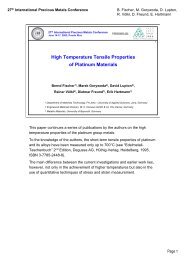
Design and Manufacture of Bushings for Glass Fibre Production
Design and Manufacture of Bushings for Glass Fibre Production
Design and Manufacture of Bushings for Glass Fibre Production

Create successful ePaper yourself
Turn your PDF publications into a flip-book with our unique Google optimized e-Paper software.
<strong>Design</strong> <strong>and</strong> <strong>Manufacture</strong> <strong>of</strong> <strong>Bushings</strong><br />
<strong>for</strong><br />
<strong>Glass</strong> <strong>Fibre</strong> <strong>Production</strong><br />
by<br />
Michael Koch <strong>and</strong> David Lupton<br />
W. C. Heraeus GmbH<br />
Engineered Materials Division<br />
Heraeusstrasse 12-14<br />
63450 Hanau, Germany<br />
Paper presented at HVG-Colloquium<br />
“<strong>Production</strong>, Properties <strong>and</strong> Applications<br />
<strong>of</strong> Refractory <strong>and</strong> Platinum Group Metals <strong>for</strong> the<br />
Contact with <strong>Glass</strong> Melts”<br />
held at the glasstec 2006<br />
Düsseldorf<br />
24 th October 2006<br />
Proceedings published by HVG Hüttentechnische Vereinigung der Deutschen<br />
Glasindustrie, Siemensstrasse 45, 63071 Offenbach am Main, Germany<br />
– 1 –
<strong>Design</strong> <strong>and</strong> <strong>Manufacture</strong> <strong>of</strong> <strong>Bushings</strong> <strong>for</strong> <strong>Glass</strong> <strong>Fibre</strong> <strong>Production</strong><br />
<strong>Design</strong> <strong>and</strong> <strong>Manufacture</strong> <strong>of</strong> <strong>Bushings</strong> <strong>for</strong> <strong>Glass</strong> <strong>Fibre</strong> <strong>Production</strong><br />
by<br />
Michael Koch <strong>and</strong> David Lupton<br />
W. C. Heraeus GmbH<br />
Engineered Materials Division<br />
Heraeusstrasse 12-14<br />
63450 Hanau<br />
Germany<br />
Historical<br />
The method <strong>of</strong> making glass fibres by means <strong>of</strong> a bushing was first demonstrated in<br />
1908 by W. von Paczinsky in Hamburg, although a British silk weaver made a glass<br />
fabric in 1842, <strong>and</strong> another inventor, Edward Libbey, exhibited a dress woven <strong>of</strong><br />
glass at the 1893 Columbian Exposition in Chicago. The manufacture <strong>of</strong> textile glass<br />
fibres using the technique <strong>of</strong> drawing the fibres through very fine orifices was<br />
developed in the 1930s in the USA <strong>and</strong> started in Germany in 1939. A useful<br />
summary <strong>of</strong> the manufacture <strong>and</strong> use <strong>of</strong> glass fibres is given in [1]. Further details<br />
are to be found <strong>for</strong> example in [2 <strong>and</strong> 3].<br />
The earliest bushings used <strong>for</strong> industrial fibre production had 51 individual nozzles or<br />
“tips”. As production processes became more stable, this was increased to 102 <strong>and</strong><br />
then 204 tips. In these early bushings, the tips were arranged in one or more long<br />
rows. Current bushings have up to 4000 tips <strong>and</strong> there is a trend to even larger<br />
numbers. In the most commonly used designs, the tips are arranged in double rows<br />
at right angles to the longitudinal axis <strong>of</strong> the bushing.<br />
Although bushings have been manufactured from a wide range <strong>of</strong> materials in the<br />
course <strong>of</strong> development, alloys <strong>of</strong> platinum with rhodium have proved to be the<br />
optimum choice because <strong>of</strong> their unique combination <strong>of</strong> high temperature strength<br />
with excellent resistance to oxidation by the surrounding air <strong>and</strong> corrosion resistance<br />
to the molten glass. Heraeus has been manufacturing bushings <strong>for</strong> textile glass fibre<br />
production since 1970.<br />
What are glass fibre bushings <strong>and</strong> how do they work?<br />
<strong>Bushings</strong> are, in their simplest <strong>for</strong>m, boxes made from platinum alloys <strong>and</strong> having a<br />
large number <strong>of</strong> small nozzles or tips on their underside. Typically, the tips have an<br />
internal diameter between 1.5 <strong>and</strong> 4 mm. The bushing is fixed in place by means <strong>of</strong><br />
insulating refractory cement <strong>and</strong> is maintained at the operating temperature by direct<br />
resistance heating. <strong>Glass</strong> is maintained in a molten state with closely controlled<br />
viscosity inside the bushing <strong>and</strong> flows slowly through the tips under the influence <strong>of</strong><br />
gravity. It is, <strong>of</strong> course, essential that the temperature over the whole <strong>of</strong> the bushing<br />
– 1 –
<strong>Design</strong> <strong>and</strong> <strong>Manufacture</strong> <strong>of</strong> <strong>Bushings</strong> <strong>for</strong> <strong>Glass</strong> <strong>Fibre</strong> <strong>Production</strong><br />
base-plate or “tip-plate” is very uni<strong>for</strong>m to ensure that the flow-rate <strong>of</strong> the glass <strong>and</strong><br />
thus the final filament diameter is also uni<strong>for</strong>m within narrow limits.<br />
The glass emerging from the tips is drawn mechanically downwards at a speed <strong>of</strong> up<br />
to about a thous<strong>and</strong> metres per minute to give very fine filaments with diameters as<br />
small as 6 µm, Figure 1a. The diagram in Figure 1b shows the essential parameters<br />
in the <strong>for</strong>mation <strong>of</strong> a filament along the z-axis from a bushing tip <strong>of</strong> radius R. Θ is the<br />
angle between the tangent to the glass meniscus <strong>and</strong> the z-axis.<br />
Figure 1a: Bushing in service.<br />
Figure 1b: Filament <strong>for</strong>mation at tip.<br />
Figure 1: <strong>Glass</strong> fibres <strong>for</strong>ming at the tips <strong>of</strong> a bushing.<br />
For the production <strong>of</strong> continuous fibres, the filaments run from the bushing to a<br />
common collecting point where size is applied <strong>and</strong> they are subsequently brought<br />
together as bundles or “str<strong>and</strong>s” on a high speed winder.[4] In special cases, the<br />
filaments are drawn by high-speed flowing air which, <strong>of</strong> course, produces a mat <strong>of</strong><br />
fibres.<br />
There are two fundamentally different methods used <strong>for</strong> manufacturing glass fibres<br />
with bushings, i.e. the indirect or “marble” melt process <strong>and</strong> the direct melt process,<br />
Figures 2a <strong>and</strong> 2b.<br />
Indirect or “marble” melt process<br />
The bushing is fed with pellets or marbles <strong>of</strong> solid glass which have been<br />
manufactured in a separate process. The marbles are charged onto a horizontal<br />
per<strong>for</strong>ated sheet where the glass melts <strong>and</strong> flows through the per<strong>for</strong>ations into the<br />
lower chamber <strong>of</strong> the bushing. The tip-plate is typically about 20-50 mm below the<br />
per<strong>for</strong>ated sheet. Although the melting <strong>and</strong> fiberising processes are essentially<br />
independent, it is essential that the level <strong>of</strong> glass in this lower chamber is kept<br />
– 2 –
<strong>Design</strong> <strong>and</strong> <strong>Manufacture</strong> <strong>of</strong> <strong>Bushings</strong> <strong>for</strong> <strong>Glass</strong> <strong>Fibre</strong> <strong>Production</strong><br />
constant, i.e. the rate <strong>of</strong> glass melting on the per<strong>for</strong>ated sheet must closely match the<br />
rate <strong>of</strong> fibre drawing. This is achieved by careful temperature control both in the<br />
design <strong>and</strong> the operation <strong>of</strong> the bushing.<br />
Figure 2a: Indirect or marble bushing.<br />
Figure 2b: Direct melt bushing.<br />
Figure 2: Operating principle <strong>of</strong> bushings <strong>for</strong> indirect <strong>and</strong> direct melt processes.<br />
Direct melt process<br />
This single-stage process is now the most widely used method <strong>for</strong> the production <strong>of</strong><br />
textile glass fibres. A number <strong>of</strong> bushings are fed with molten glass directly from a<br />
central melting furnace or “tank” via a channel or “<strong>for</strong>ehearth”. The glass flows into<br />
the bushing through a finely per<strong>for</strong>ated sheet which serves mainly to homogenise the<br />
temperature distribution in the molten glass. The fibres are again drawn through the<br />
tips in the tip-plate <strong>of</strong> the bushing.<br />
Methods <strong>for</strong> manufacturing glass fibre bushings<br />
Heraeus has two basic techniques <strong>for</strong> manufacturing the tip-plates <strong>of</strong> bushings. In the<br />
first process, the tips are cut from seamless drawn platinum alloy tubes which are<br />
then inserted into a plate with pre-punched holes <strong>and</strong> welded into position. With the<br />
second technique, a thicker sheet is used <strong>and</strong> the tips are pressed from this sheet by<br />
– 3 –
<strong>Design</strong> <strong>and</strong> <strong>Manufacture</strong> <strong>of</strong> <strong>Bushings</strong> <strong>for</strong> <strong>Glass</strong> <strong>Fibre</strong> <strong>Production</strong><br />
a type <strong>of</strong> deep-drawing operation. The upper side <strong>of</strong> the tip-plate <strong>and</strong> the lower ends<br />
<strong>of</strong> the tips are then precision machined to meet final tolerances.<br />
Welded tips<br />
The main advantage <strong>of</strong> bushings with welded tips is that no special tooling is needed,<br />
Figures 3a <strong>and</strong> 3b. The manufacturing process is there<strong>for</strong>e very flexible, especially<br />
<strong>for</strong> small batch sizes. The layout <strong>of</strong> the tips in the tip-plate – in particular the<br />
diameters <strong>of</strong> the tips <strong>and</strong> the gaps between them – can be selected entirely to meet<br />
the requirements <strong>of</strong> the fibre drawing process without regard to the complexities <strong>of</strong><br />
metal <strong>for</strong>ming operations. It is also possible to position the tips closer together than<br />
with the pressed tips. A further advantage is the feasibility <strong>of</strong> using different materials<br />
<strong>for</strong> the tip-plate <strong>and</strong> the tips.<br />
Figure 3a: Schematic design.<br />
Figure 3: Bushing with welded tips.<br />
Figure 3b: Typical example.<br />
A potential disadvantage <strong>of</strong> bushings with welded tips is the risk <strong>of</strong> leaks at the weld<br />
joints. It is essential to use a thoroughly qualified welding process <strong>and</strong> to carry out<br />
detailed visual <strong>and</strong> dye-penetration inspections be<strong>for</strong>e releasing the bushing.<br />
Heraeus has found that manual TIG welding <strong>of</strong>fers the most reliable results, but<br />
some manufacturers use laser welding <strong>and</strong> other techniques.<br />
Pressed tips<br />
The main advantage <strong>of</strong> tip-plates with pressed tips is the good mechanical stability<br />
resulting from the monolithic design <strong>and</strong> the tapered, conical <strong>for</strong>m <strong>of</strong> the tips, Figures<br />
4a <strong>and</strong> 4b. Additionally, the tip-plate is free from any weld seams through its<br />
thickness.<br />
– 4 –
<strong>Design</strong> <strong>and</strong> <strong>Manufacture</strong> <strong>of</strong> <strong>Bushings</strong> <strong>for</strong> <strong>Glass</strong> <strong>Fibre</strong> <strong>Production</strong><br />
Figure 4a: Schematic design.<br />
Figure 4: Bushing with pressed tips.<br />
Figure 4b: Typical example.<br />
The main disadvantages <strong>of</strong> designs with pressed tips are the relatively high tooling<br />
cost <strong>and</strong> the time delay if new tooling has to be manufactured. Furthermore, each tipplate<br />
design requires its own tooling. The thickness tolerances that can be achieved<br />
<strong>for</strong> the tip-plate are less precise than <strong>for</strong> the rolled sheet used in making tip-plates<br />
with welded tips. It is, <strong>of</strong> course, not possible to use different materials <strong>for</strong> tips <strong>and</strong><br />
plate.<br />
<strong>Glass</strong> quality<br />
Table 1 shows typical compositions <strong>of</strong> the main glasses used <strong>for</strong> fibres. Platinum<br />
alloys are used <strong>for</strong> bushings because <strong>of</strong> their excellent oxidation <strong>and</strong> corrosion<br />
resistance. However, they are susceptible to attack by “platinum poisons” –<br />
elements which <strong>for</strong>m low-melting eutectics or brittle compounds with the platinum. A<br />
number <strong>of</strong> these “poisons” can develop if the glass processing conditions are<br />
insufficiently oxidising. One <strong>of</strong> the best known examples is silicon which <strong>for</strong>ms a<br />
eutectic with platinum melting at only 830°C. Less well known is the reaction <strong>of</strong> the<br />
rhodium constituent <strong>of</strong> Pt-Rh alloys with sulphur to <strong>for</strong>m a eutectic which melts at<br />
925°C. Under sufficiently reducing conditions, even the highly stable oxide Al 2 O 3 can<br />
be reduced at the surface <strong>of</strong> platinum: the aluminium diffuses into the platinum<br />
causing embrittlement. The insufficiently oxidising conditions may be the result <strong>of</strong><br />
carbon impurities in the raw materials, incorrect adjustment <strong>of</strong> the oxygen potential in<br />
the furnace atmosphere or unintentional galvanic effects in the electrical heating<br />
system.<br />
– 5 –
<strong>Design</strong> <strong>and</strong> <strong>Manufacture</strong> <strong>of</strong> <strong>Bushings</strong> <strong>for</strong> <strong>Glass</strong> <strong>Fibre</strong> <strong>Production</strong><br />
Table 1: Typical glass compositions.<br />
– 6 –
<strong>Design</strong> <strong>and</strong> <strong>Manufacture</strong> <strong>of</strong> <strong>Bushings</strong> <strong>for</strong> <strong>Glass</strong> <strong>Fibre</strong> <strong>Production</strong><br />
Bushing design<br />
Many constraints <strong>and</strong> parameters must be considered in the design <strong>of</strong> a bushing.<br />
The basic geometrical aspects relate to the type <strong>of</strong> fibres to be produced <strong>and</strong> the<br />
choice <strong>of</strong> the melt system (indirect or direct). The thermal household is, however,<br />
also <strong>of</strong> fundamental importance. The aim <strong>of</strong> the fiberising process is to produce<br />
filaments with a uni<strong>for</strong>m diameter. This is only possible if the temperature <strong>of</strong> the glass<br />
as it leaves the bushing via all the tips is uni<strong>for</strong>m to within a few degrees. Marble<br />
bushings are subject to the additional constraint that a considerable amount <strong>of</strong><br />
electrical energy is required to melt the marbles on the upper per<strong>for</strong>ated sheet. The<br />
electrical design <strong>of</strong> a bushing can be considered as a number <strong>of</strong> resistors connected<br />
in parallel, the individual resistors being the walls, sheets <strong>and</strong> plates.<br />
The electrical connecting flanges are <strong>of</strong> decisive importance in achieving a<br />
homogeneous temperature distribution in the bushing. Typical designs <strong>of</strong> connecting<br />
flanges are shown in Figures 5a, 5b <strong>and</strong> 5c. The electrical energy is introduced by<br />
means <strong>of</strong> water-cooled copper clamps. The clamps also remove thermal energy <strong>and</strong><br />
can thus be used <strong>for</strong> cooling specific parts <strong>of</strong> the bushing .<br />
Figure 5: Three typical examples <strong>of</strong> electrical connecting flanges.<br />
The tip-plate is the essential feature <strong>of</strong> the bushing. The larger the tip-plate, the<br />
greater the danger that it will start to sag in operation. Sagging has two negative<br />
effects on the function <strong>of</strong> the bushing: the hydrostatic head <strong>of</strong> glass is no longer<br />
uni<strong>for</strong>m over the whole area <strong>of</strong> the tip-plate, <strong>and</strong> the tips are no longer parallel to<br />
each other. Double bottom-plates are supported additionally by a central support<br />
along the longitudinal axis, thus ensuring greater mechanical stability, Figure 6. The<br />
stability <strong>of</strong> single tip-plates can only be increased by numerous rein<strong>for</strong>cement ribs<br />
inside the bushing.<br />
– 7 –
<strong>Design</strong> <strong>and</strong> <strong>Manufacture</strong> <strong>of</strong> <strong>Bushings</strong> <strong>for</strong> <strong>Glass</strong> <strong>Fibre</strong> <strong>Production</strong><br />
Figure 6: Bushing with double bottom plate <strong>for</strong> increased mechanical stability.<br />
It is normal practice to cool the glass fibres as they leave the bushing by means <strong>of</strong><br />
cooling fins, Figures 7a <strong>and</strong> 7b. These have the additional function <strong>of</strong> cooling the<br />
lower part <strong>of</strong> the tips to increase the glass viscosity at the point where the fibre<br />
drawing occurs. Important features are both the material <strong>and</strong> the dimensions <strong>of</strong> the<br />
fins. Typical materials used are copper, which may be plated with nickel or silver, or<br />
water-cooled palladium.<br />
To increase the output <strong>of</strong> bushings, increasingly large tip-counts are being used.<br />
<strong>Bushings</strong> with 4000 tips are now in common use, whereas individual fibre<br />
manufacturers are already using 6000-tip bushings. However, as there is a practical<br />
limit to the physical size <strong>of</strong> the bottom-plate because <strong>of</strong> the stability requirement, an<br />
increase in the tip-count can only be achieved by an increase in the tips per unit area<br />
– a gap <strong>of</strong> only 0.8 mm between tips can now be achieved with a tip-plate thickness<br />
<strong>of</strong> 1.5 mm.<br />
A further design feature is the geometry <strong>of</strong> the tip which influences both the fibre<br />
quality <strong>and</strong> the per<strong>for</strong>mance <strong>of</strong> the bushing. Modern techniques <strong>of</strong> metal <strong>for</strong>ming <strong>and</strong><br />
machining permit a wide variety <strong>of</strong> geometries. Heraeus has, <strong>for</strong> example, about 20<br />
geometries in the st<strong>and</strong>ard product range.<br />
– 8 –
<strong>Design</strong> <strong>and</strong> <strong>Manufacture</strong> <strong>of</strong> <strong>Bushings</strong> <strong>for</strong> <strong>Glass</strong> <strong>Fibre</strong> <strong>Production</strong><br />
Figure 7a: Small unit <strong>of</strong> cooling fins. Figure 7b: Cooling fins in fibre drawing process<br />
Figure 7: Cooling fins.<br />
<strong>Manufacture</strong> <strong>of</strong> bushings<br />
The manufacturing quality is <strong>of</strong> critical importance <strong>for</strong> the service life <strong>of</strong> the bushing. It<br />
is essential that the materials used have a high level <strong>of</strong> purity. Joints between sheets<br />
<strong>and</strong> other parts are only acceptable if the welds are free from all defects. The<br />
integrity <strong>of</strong> all welds must be inspected by a dye-penetrant test. The tolerances <strong>of</strong> all<br />
sheets, tubes <strong>and</strong> wires must be maintained within very tight limits to ensure the<br />
problem-free function <strong>of</strong> the bushing regarding temperature homogeneity <strong>and</strong><br />
mechanical stability. The achievement <strong>of</strong> closely defined tolerances is also important<br />
in optimising the weight <strong>of</strong> precious metal used in the bushing.<br />
Another factor in minimising the weight <strong>of</strong> bushings is the possibility <strong>of</strong> combining<br />
different Pt-Rh materials to optimise strength in the components where stability is<br />
particularly needed. A typical example is the use <strong>of</strong> an oxide dispersion hardened<br />
alloy, e.g. Pt-10%Rh DPH, <strong>for</strong> the tip-plate to reduce sagging. The DPH materials<br />
have considerably higher creep strength than the conventional alloys at high<br />
temperatures.[5]<br />
<strong>Glass</strong> <strong>for</strong>ming operation<br />
Be<strong>for</strong>e the bushing is taken into operation, it must be cautiously embedded in a high<br />
purity refractory cement. It is absolutely essential that the bushing should be able to<br />
exp<strong>and</strong> <strong>and</strong> contract freely. The thermal expansion <strong>of</strong> the bushing during heating to<br />
the operating temperature is very considerable (typically several millimetres over the<br />
length <strong>of</strong> the bushing). The heating operation – <strong>and</strong> any subsequent cooling<br />
operations <strong>for</strong> cleaning or repair – must be carried out slowly to minimise thermally<br />
– 9 –
<strong>Design</strong> <strong>and</strong> <strong>Manufacture</strong> <strong>of</strong> <strong>Bushings</strong> <strong>for</strong> <strong>Glass</strong> <strong>Fibre</strong> <strong>Production</strong><br />
induced stresses which arise due to temperature gradients within the bushing <strong>and</strong><br />
between the bushing <strong>and</strong> surrounding refractories.[6] The expansion <strong>of</strong> the bushing<br />
must not be hindered by the electrical contact clamps. Additionally, it is generally<br />
recommended to bond a layer <strong>of</strong> alumina fibre felt to the bushing to prevent direct<br />
contact with the cement. Apart from reducing stresses, the felt protects the bushing<br />
from corrosion by impurities in the cement <strong>and</strong> reduces metal losses resulting from<br />
the oxidation <strong>and</strong> evaporation <strong>of</strong> the platinum <strong>and</strong> rhodium constituents in the alloy.<br />
A further, rather sensitive aspect with regard to the service life <strong>of</strong> a bushing is the<br />
qualification <strong>of</strong> the operative responsible <strong>for</strong> the bushing in service. For example, it is<br />
extremely important that, when removing glass from between the tips with the<br />
commonly used steel wires, the wire is not allowed to touch the tip-plate. This can<br />
lead to a contamination <strong>of</strong> the platinum with impurities which diffuse into the platinum<br />
alloy in the affected areas <strong>and</strong> then cause corrosion damage or even embrittlement<br />
<strong>of</strong> the material.<br />
When cleaning the cooling fins it is essential to ensure that the tip-plate is not cooled<br />
excessively. The rapid cooling in this region causes the heating power to increase<br />
very rapidly which can result in the joints to the connecting flanges overheating <strong>and</strong><br />
melting.<br />
The glass processing steps prior to the fiberisation also play a major role in the<br />
function <strong>of</strong> the bushing. Defects in the glass stream which are caused by faults in the<br />
melting process cannot be corrected by the bushing. Temperature variations in the<br />
glass, <strong>for</strong> example, cannot be compensated by the bushing. Undissolved solid<br />
particles <strong>of</strong> the glass batch components clog the per<strong>for</strong>ated sheet <strong>and</strong> can also act<br />
as nuclei <strong>for</strong> crystallisation. In extreme cases, impurities in the glass can destroy a<br />
bushing within a few hours.<br />
Future developments<br />
One <strong>of</strong> the most important developments will be the wide-scale implementation <strong>of</strong><br />
bushings with tip-counts <strong>of</strong> more than 4000. This will, in turn, lead to bushing designs<br />
with a higher density <strong>of</strong> tips on the tip-plate <strong>and</strong> reduced gaps between the tips. The<br />
reduced gap size will m<strong>and</strong>ate the welded design <strong>of</strong> tip-plate, but it is likely that the<br />
tips will be specially <strong>for</strong>med to simulate the shape <strong>of</strong> pressed tips in order to increase<br />
their stability.<br />
It is to be expected that the oxide dispersion hardened Pt-Rh DPH materials will be<br />
used increasingly in bushings. For example, in [5] it was demonstrated that the<br />
weight <strong>of</strong> a marble-bushing <strong>for</strong> C-glass could be reduced by 8.7% <strong>and</strong> the service life<br />
doubled by converting from conventional Pt-10%Rh to Pt-10%Rh DPH.<br />
The increasing use <strong>of</strong> finite element modelling (FEM) is leading to significant<br />
advances in both the mechanical <strong>and</strong> thermal design <strong>of</strong> bushings. FEM permits, <strong>for</strong><br />
example, the redesign <strong>of</strong> critically stressed components, the optimisation <strong>of</strong> operating<br />
– 10 –
<strong>Design</strong> <strong>and</strong> <strong>Manufacture</strong> <strong>of</strong> <strong>Bushings</strong> <strong>for</strong> <strong>Glass</strong> <strong>Fibre</strong> <strong>Production</strong><br />
conditions <strong>and</strong> the selection <strong>of</strong> the most appropriate structural materials.[6] An<br />
example <strong>of</strong> the redesign <strong>of</strong> part <strong>of</strong> a bushing is shown in Figure 8.<br />
Figure 8a: Stresses caused by the<br />
temperature pr<strong>of</strong>ile shown in Figure 8c in<br />
original bushing.<br />
Figure 8b: Stresses caused by the<br />
temperature pr<strong>of</strong>ile shown in Figure 8c in<br />
modified bushing.<br />
Figure 8: Example <strong>for</strong> redesign <strong>of</strong><br />
bushing segment using FEM to minimise<br />
stress concentrations, from [6]<br />
Figure 8c: Temperature pr<strong>of</strong>ile in a<br />
segment <strong>of</strong> a bushing<br />
Acknowledgements<br />
We are grateful to Kari Salonaho, Dr. Roman Teschner <strong>and</strong> Jürgen Woltz <strong>for</strong> their<br />
useful contributions <strong>and</strong> constructive discussions regarding the practical applications<br />
<strong>of</strong> glass fibre bushings.<br />
– 11 –
<strong>Design</strong> <strong>and</strong> <strong>Manufacture</strong> <strong>of</strong> <strong>Bushings</strong> <strong>for</strong> <strong>Glass</strong> <strong>Fibre</strong> <strong>Production</strong><br />
References<br />
1. http://www.madehow.com/Volume-2/Fiberglass.html<br />
2. P. F. Aubourg, C. Crall, J. Hadley, R.D. Kaverman, <strong>and</strong> D.M. Miller, “<strong>Glass</strong><br />
Fibers, Ceramics <strong>and</strong> <strong>Glass</strong>es,” in Engineered Materials H<strong>and</strong>book, Vol. 4.<br />
ASM International, 1991, pp. 1027-31<br />
3. F. V. Tooley, “Fiberglass, Ceramics <strong>and</strong> <strong>Glass</strong>es,” in Engineered Materials<br />
H<strong>and</strong>book, Vol. 4. ASM International, 1991, pp. 402-8<br />
4. http://www.britglass.org.uk/Files/<strong>for</strong>m3<strong>Glass</strong>_<strong>Fibre</strong>_<strong>Manufacture</strong>.pdf<br />
5. B. Fischer, “New Platinum Materials <strong>for</strong> High Temperature Applications”,<br />
Advanced Engineering Materials, 2001, 3(10), pp. 811-820<br />
6. R. Völkl, B. Fischer, R. Teschner, D. F. Lupton, “Finite Element Modelling <strong>of</strong><br />
Strains <strong>and</strong> Stresses in Platinum Alloy <strong>Bushings</strong> <strong>for</strong> Textile <strong>Glass</strong> <strong>Fibre</strong><br />
<strong>Production</strong>”, <strong>Glass</strong> Science <strong>and</strong> Technology / Glastechnische Berichte, 2001,<br />
74, pp. 142-151<br />
– 12 –