SECTION 08710 HARDWARE - Sargent Locks
SECTION 08710 HARDWARE - Sargent Locks
SECTION 08710 HARDWARE - Sargent Locks

You also want an ePaper? Increase the reach of your titles
YUMPU automatically turns print PDFs into web optimized ePapers that Google loves.
<strong>SECTION</strong> <strong>08710</strong><br />
<strong>HARDWARE</strong><br />
PART 1 GENERAL<br />
1.1 SUMMARY<br />
A. Section Includes:<br />
1. Finish hardware for doors as specified and as listed in "Hardware Groups" and required by<br />
actual conditions.<br />
2. Include screws, special screws, bolts, special bolts, expansion shields, and other devices<br />
for proper application of hardware.<br />
B. Related Sections:<br />
1. Section 06101: Carpentry 1. Section 08110, Section 08120, and Section 08211 - Certain<br />
hardware items installed with doors.<br />
2. Division 16: Electrical.<br />
1.2 GENERAL REQUIREMENTS<br />
A. Provide items, articles, materials, operations and methods listed, mentioned or scheduled<br />
herein or on drawings, in quantities as required to complete project. Provide hardware that<br />
functions properly. Prior to furnishing hardware, advise Architect of items that will not operate<br />
properly, are improper for conditions, or will not remain permanently anchored.<br />
1.3 SUBMITTALS<br />
A. Hardware Schedule: Submit 5 copies of hardware schedule in vertical format as illustrated by<br />
the Sequence of Format for the Hardware Schedule as published by the Door and Hardware<br />
Institute. Schedules, which do not comply, will be returned for correction before checking.<br />
Hardware schedule shall clearly indicate architect's hardware group and manufacturer of each<br />
item proposed. The schedule shall be reviewed prior to submission by a certified Architectural<br />
Hardware Consultant, who shall affix his or her seal attesting to the completeness and<br />
correctness of the schedule.<br />
1. Provide 2 copies of illustrations from manufacturer’s catalogs and data in brochure form.<br />
2. Check specified hardware for suitability and adaptability to details and surrounding<br />
conditions. Indicate unsuitable or incompatible items and proposed substitutions in<br />
hardware schedule.<br />
3. Provide listing of manufacturer's template numbers for each item of hardware in hardware<br />
schedule.<br />
4. Furnish other Contractors and Subcontractors concerned with copies of final approved<br />
hardware schedule. Submit necessary templates and schedules as soon as possible to<br />
hollow metal, wood door, and aluminum door fabricators in accordance with schedule they<br />
require for fabrication.<br />
5. Samples: Lever design or finish sample: Provide 3 samples if requested by architect.<br />
B. Wiring Diagrams: Provide complete and detailed system operation and elevation diagrams<br />
specially developed for each opening requiring electrified hardware, except openings where<br />
only magnetic hold-opens or door position switches are specified. Provide these diagrams with<br />
hardware schedule submittal for approval. Provide detailed wiring diagrams with hardware<br />
delivery to jobsite.<br />
C. Installation Instructions: Provide manufacturer's written installation and adjustment instructions<br />
for finish hardware. Send installation instructions to site with hardware.<br />
D. Templates: Submit templates and "reviewed Hardware Schedule" to door and frame supplier<br />
and others as applicable to enable proper and accurate sizing and locations of cutouts and<br />
reinforcing.<br />
<strong>Sargent</strong><br />
Hardware<br />
09/08/03 <strong>08710</strong> - 1
E. Contract Closeout Submittals: Comply with Section 01700 including specific requirements<br />
indicated.<br />
1. Operating and maintenance manuals: Submit 3 sets containing the following:<br />
a. Complete information in care, maintenance, and adjustment, and data on repair and<br />
replacement parts, and information on preservation of finishes.<br />
b. Catalog pages for each product.<br />
c. Name, address, and phone number of local representative for each manufacturer.<br />
d. Parts list for each product.<br />
2. Copy of final approved hardware schedule, edited to reflect "As installed".<br />
3. Copy of final keying schedule.<br />
4. As installed "Wiring Diagrams" for each opening connected to power, both low voltage and<br />
110 volts.<br />
5. One complete set of special tools required for maintenance and adjustment of hardware,<br />
including changing of cylinders.<br />
1.4 QUALITY ASSURANCE<br />
A. Manufacturer: Obtain each type of hardware (ie. latch and locksets, hinges, closers) from single<br />
manufacturer, although several may be indicated as offering products complying with<br />
requirements.<br />
B. Supplier: Recognized architectural finish hardware supplier, with warehousing facilities, who has<br />
been providing hardware for period of not less than 3 years. The supplier shall be, or employ, a<br />
certified Architectural Hardware Consultant (AHC), who is registered in the continuing education<br />
program as administered by the Door and Hardware Institute. The hardware schedule shall be<br />
prepared and signed by a certified AHC.<br />
C. Installer: Firm with 3 years experience in installation of similar hardware to that required for this<br />
project, including specific requirements indicated.<br />
D. Regulatory Label Requirements: Provide nationally recognized testing agency label or stamp<br />
on hardware for labeled openings. Where UL requirements conflict with drawings or<br />
specifications, hardware conforming to UL requirements shall be provided. Conflicts and<br />
proposed substitutions shall be clearly indicated in hardware schedule.<br />
E. Handicapped Requirements: Doors to stairs (other than exit stairs), loading platforms, boiler<br />
rooms, stages and doors serving other hazardous locations shall have knurled or other similar<br />
approved marking of door lever handles or cross bars in accordance with local building codes.<br />
F. Pre-Installation Conference: Prior to the installation of hardware, manufacturer's<br />
representatives for locksets, closers, and exit devices shall arrange and hold a jobsite meeting<br />
to instruct the installing contractor's personnel on the proper installation of their respective<br />
products. A letter of compliance, indicating when this meeting is held and who is in attendance,<br />
shall be sent to the Architect and Owner.<br />
1.5 DELIVERY, STORAGE AND HANDLING<br />
A. Deliver hardware to jobsite in manufacturer's original packaging, marked to correspond with<br />
approved hardware schedule. Do not deliver hardware until suitable locked storage space is<br />
available. Check hardware against reviewed hardware schedule. Store hardware to protect<br />
against loss, theft or damage.<br />
B. Deliver hardware required to be installed during fabrication of hollow metal, aluminum, wood, or<br />
stainless steel doors prepaid to manufacturer.<br />
1.6 WARRANTY<br />
A. Guarantee workmanship and material provided against defective manufacture. Repair or<br />
replace defective workmanship and material appearing within period of one year after<br />
Substantial Completion.<br />
B. Provide ten year factory warranty on door closer body against defects in material and<br />
workmanship from date of occupancy of Project.<br />
<strong>Sargent</strong><br />
Hardware<br />
09/08/03 <strong>08710</strong> - 2
C. Replace shortages and incorrect items with correct material at no additional cost to Owner.<br />
D. At completion of project, qualified factory representative shall inspect closer installations. After<br />
this inspection, letter shall be sent to Architect reporting on conditions, verifying that closers<br />
have been properly installed and adjusted.<br />
PART 2 PRODUCTS<br />
2.1 AUTOMATIC OPERATORS<br />
A. Acceptable Manufacturers:<br />
<strong>Sargent</strong> Besam Norton<br />
4000 Series PowerSwing 6900<br />
B. Provide automatic operators as specified in hardware groups. Provide complete with drop<br />
plates, brackets, or adapters for arms as required to suit details.<br />
C. Provide wall-mounted actuator switches by the same manufacturer as the operator. Actuators<br />
shall be weather-resistant type at exterior applications.<br />
2.2 LOW ENERGY DOOR OPERATORS<br />
A. Low energy door operators shall be 4000 Series as manufactured by SARGENT Manufacturing<br />
Company, New Haven, CT.<br />
B. Low energy door operators shall meet ANSI/BHMA A156.19 requirements.<br />
C. Low energy door operators shall meet UL, cUL, UL10c, and UL10B standards for use on fire<br />
doors.<br />
D. Low energy door operators shall have the following adjustments:<br />
1. Motor assist shall be adjustable from 0 to 30 seconds in 5 second increments.<br />
2. Door control shall be adjustable to provide compliance with the requirements of the<br />
Americans with Disabilities Act (ADA).<br />
3. Door closing force and backcheck shall be adjustable<br />
4. Motor start up delay.<br />
5. Vestibule interface delay.<br />
6. Electric lock delay.<br />
7. Door hold open delay up to 30 seconds.<br />
E. Operator units shall provide conventional door closer opening and closing forces unless the<br />
power operator motor is activated by an initiating device.<br />
F. Operator units shall have a three position selector mode switch that shall permit units to be<br />
switched “ON” to monitor for function activation, “HO” for indefinite hold open function, or “OFF”<br />
which shall deactivate all control functions but will allow standard door operation by means of<br />
the internal mechanical closer.<br />
G. Operators shall have push and go function to activate power operator or power assist<br />
functions.<br />
H. Operator units shall have door closer assembly with adjustable spring size, backcheck valve,<br />
sweep valve, latch valve, speed control valve, and pressure adjustment valve to control door<br />
closing.<br />
<strong>Sargent</strong><br />
Hardware<br />
09/08/03 <strong>08710</strong> - 3
I. Operator units shall have inputs for smoke ventilation doors, which allow doors to power open<br />
upon fire alarm activation and hold open indefinitely or until fire alarm is reset.<br />
J. Operator units shall have a presence detector input to prevent a closed door from opening or a<br />
door that is fully opened from closing.<br />
K. Operator units shall have a hold open toggle input to allow remote activation for indefinite hold<br />
open; door shall close the second time the input is activated.<br />
L. Operator units shall have vestibule inputs to allow sequencing operation of two units.<br />
M. Operators shall have a SPDT relay for interfacing with latching or locking devices.<br />
2.3 BUTTS AND HINGES<br />
A. Acceptable Manufacturers and Types:<br />
Type McKinney<br />
Type 1 T4A3795<br />
Type 2 TA2714<br />
Type 3 TA2314<br />
Type 4 T4A3786<br />
Type 5 T4A3386<br />
B. Application:<br />
1. Exterior outswinging doors Type 5 x NRP<br />
2. Exterior inswinging doors and vestibule doors Type 4<br />
3. Interior doors with closers Type 2 or 4<br />
4. Interior doors over 36 inches wide Type 4<br />
5. Interior doors 36 inches or less without closer Type 2<br />
6. Provide NRP (non-removable pins) at out-swinging lockable doors.<br />
C. Size:<br />
1. 2-1/4 inch Doors 5 inch by 5 inch<br />
2. 1-3/4 inch Doors 4-1/2 inch by 4-1/2 inch<br />
3. 1-3/8 inch Doors 3-1/3 inch by 3-1/2 inch<br />
D. Quantity:<br />
1. 2 - hinges per leaf for openings through 60 inches high.<br />
2. 1 - additional hinge per leaf for each additional 30 inches in height or fraction thereof.<br />
3. 4 - Dutch doors up to 90 inches in height.<br />
E. Drill 5/32 inch hole and use No. 12, 1-1/4 inch steel threaded to the head wood screws for<br />
hinges on wood doors.<br />
2.4 ELECTRIC HINGES<br />
A. Acceptable manufacturers:<br />
McKinney<br />
CC<br />
B. Provide sufficient number of concealed wires to accommodate electric function of specified<br />
hardware.<br />
C. Electric hinges to be located at second hinge from bottom. Where electric hinges are used in<br />
conjunction with exit devices, locate hinge nearest to exit device.<br />
D. Provide mortar guard similar to McKinney MG-16 for each electric hinge specified.<br />
<strong>Sargent</strong><br />
Hardware<br />
09/08/03 <strong>08710</strong> - 4
2.5 CONTINUOUS HINGES<br />
A. Acceptable manufacturers:<br />
McKinney<br />
MCK-12HD<br />
MCK-25HD<br />
B. Provide one of the above two models of continuous hinges as appropriate for the type,<br />
inset,and thickness of door where specified. Coordinate hinge types with the door supplier.<br />
2.6 FLOOR CLOSERS AND INTERMEDIATE PIVOTS<br />
A. Acceptable Manufacturer and Series:<br />
Rixson<br />
27 Series<br />
M19<br />
B. Floor closers shall be complete with ball-bearing top pivot, floor plates, intermediate pivots and<br />
cement boxes unless indicated otherwise. One intermediate pivot for doors less than 91 inches<br />
high. Two intermediate pivots for doors between 91 inches and 121 inches high. Intermediate<br />
pivots spaced equally not less than 25 inches or not more than 35 inches on center, for doors<br />
over 121 inches high.<br />
C. Provide single-acting offset hung floor closers as specified in Hardware Groups.<br />
D. Provide floor closers with adjustable swing speed, latch speed, back-check, and automatic<br />
hold-open features. Closer shall have built in positive stop at specified degree of opening.<br />
E. Floor closers shall meet maximum opening force requirements of ADA.<br />
2.7 PIVOT SETS<br />
A. Acceptable Manufacturer and Series:<br />
Type<br />
Rixson<br />
Offset, std. duty 117<br />
Offset, hvy. duty 147<br />
Intermed.<br />
M19<br />
Center, std. duty 1282<br />
Center, hvy. duty 370<br />
B. Pivot sets shall be complete with oil-impregnated top pivot, unless indicated otherwise. For<br />
offset pivoted doors, provide one intermediate pivot for doors less than 91 inches high. Two<br />
intermediate pivots for doors between 91 inches and 121 inches high. Intermediate pivots<br />
spaced equally not less than 25 inches or not more than 35 inches on center, for doors over<br />
121 inches high.<br />
C. Provide pivot sets as specified in Hardware Groups.<br />
2.8 FLUSH BOLTS AND DUSTPROOF STRIKES<br />
A. Acceptable manufacturers:<br />
Trimco<br />
3915<br />
3810<br />
3815<br />
<strong>Sargent</strong><br />
Hardware<br />
09/08/03 <strong>08710</strong> - 5
3910<br />
B. Non-labeled Openings: Provide 2 flush bolts 3915 for inactive leaf of pairs of locked and<br />
latched doors. Locate centerline of top bolt not more than 78 inches from finished floor.<br />
Provide dustproof strike 3910 for bottom bolt.<br />
C. Labeled Openings: Provide automatic flush bolt set 3810 or 3815, as applicable, for inactive<br />
leaf of pairs of doors. Provide dustproof strike 3910 for bottom bolt.<br />
2.9 LOCKSETS – MORTISE<br />
A. Acceptable Manufacturer and Series:<br />
Manufacturer<br />
<strong>Sargent</strong><br />
Yale<br />
Corbin/Russwin<br />
Series<br />
8200 x LNL<br />
8700FL x AUR<br />
ML2200 x NSA<br />
B. Provide lock functions specified in Hardware Groups, with following provisions:<br />
1. Cylinders: Manufacturer’s high security removable core 6-pin, meeting the requirements of<br />
UL437.<br />
2. Backsets: 2-3/4 inches.<br />
3. Strikes: Provide wrought boxes and strikes with proper lip length to protect trim but not to<br />
project more than 1/8 inch beyond trim, frame or inactive leaf. Where required, provide<br />
open back strike and protected to allow practical and secure operation.<br />
2.10 LOCKSETS – CYLINDRICAL<br />
A. Acceptable Manufacturer and Series:<br />
Manufacturer<br />
<strong>Sargent</strong><br />
Yale<br />
Corbin/Russwin<br />
Series<br />
10-Line x LL<br />
5400L x AU<br />
CL3400 x NZD<br />
1. Cylinders: Manufacturer’s high security removable core 6-pin, meeting the requirements of<br />
UL437.<br />
2. Backsets: 2-3/4 inches.<br />
3. Strikes: Provide wrought boxes and strikes with proper lip length to protect trim but not to<br />
project more than 1/8 inch beyond trim, frame or inactive leaf. Where required, provide<br />
open back strike and protected to allow practical and secure operation.<br />
2.11 LOCKSETS – 11-LINE<br />
A. Acceptable Manufacturer and Series (No Substitutions):<br />
Manufacturer<br />
<strong>Sargent</strong><br />
Series<br />
11-Line x LL<br />
1. <strong>Locks</strong>ets shall be able to withstand 2400 inch pounds of torque applied to the locked lever<br />
without gaining access.<br />
2. <strong>Locks</strong>ets shall be cycle tested per ANSI A156.2, 1996, to two million cycles without any<br />
visible lever sag.<br />
3. <strong>Locks</strong>ets shall be able to fit a standard 2-1/8 inch (55 mm) bore without the use of thrubolts.<br />
Standard rose size shall be 2-3/4 inches (70 mm) in diameter.<br />
4. <strong>Locks</strong>et levers shall be made of solid material with no plastic fillers.<br />
5. Latchbolt head shall be one piece stainless steel.<br />
6. Latchbolt assemblies shall be encased within the lockbody.<br />
7. Cylinders: <strong>Sargent</strong> Signature Series, UL437 listed, high security 6-pin cylinders.<br />
8. Backsets: 2-3/4 inches.<br />
<strong>Sargent</strong><br />
Hardware<br />
09/08/03 <strong>08710</strong> - 6
9. Strikes: Provide wrought boxes and strikes with proper lip length to protect trim but not to<br />
project more than 1/8 inch beyond trim, frame or inactive leaf. Where required, provide<br />
open back strike and protected to allow practical and secure operation.<br />
10. <strong>Locks</strong>ets shall have a seven year limited warranty.<br />
2.12 SLIDING DOOR PRIVACY LOCKS<br />
A. Acceptable Manufacturers:<br />
Quality<br />
101 PD<br />
2.13 EMERGENCY DOOR STOP RELEASE AND STRIKE<br />
A. Acceptable Manufacturers:<br />
McKinney<br />
CSS-9<br />
B. Provide combination emergency stop and strike to allow door to swing open in opposite<br />
direction. Size for specific frame depth.<br />
2.14 EXIT DEVICES<br />
A. Acceptable Manufacturers:<br />
<strong>Sargent</strong><br />
80 Series<br />
B. Provide exit device series and functions as specified in Hardware Groups. <strong>Sargent</strong> product<br />
numbers are referenced in the Hardware Groups.<br />
C. All exit devices shall be UL listed for panic. Exit devices for labeled doors shall be UL listed as<br />
"Fire Exit Hardware".<br />
D. Where lever trim is specified, provide lever design to match lockset levers.<br />
E. Provide cylinders for exit devices with locking trim and cylinder dogging.<br />
F. Provide cylinder dogging feature for non-rated exit devices.<br />
G. Provide keyed removable mullions, as specified in the Hardware Groups.<br />
2.15 HOSPITAL LATCHES<br />
A. Acceptable Manufacturers and Series:<br />
<strong>Sargent</strong><br />
115P<br />
B. Provide hospital latches as specified, with covers engraved "Push" and "Pull."<br />
C. Provide 5 inch backset for hospital latches, unless noted otherwise.<br />
2.16 ELECTRIC STRIKES<br />
A. Acceptable Manufacturers and Series:<br />
HES<br />
Folger-Adam<br />
1003 Series 310 Series<br />
<strong>Sargent</strong><br />
Hardware<br />
09/08/03 <strong>08710</strong> - 7
B. Provide electric strikes designed for use with the type locks shown at each opening where<br />
specified.<br />
C. Electric Strikes shall be UL Listed as Burglary-Resistant Electric Door Strikes and where<br />
required shall be UL Listed as Electric Strikes for Fire Doors and Frames. Provide non fail-safe<br />
type electric strikes, unless specified otherwise.<br />
D. Provide transformers and rectifiers for each strike as required. Verify voltage with electrical<br />
contractor.<br />
2.17 MAGNETIC LOCKS<br />
A. Acceptable Manufacturers and Series:<br />
<strong>Sargent</strong> Securitron<br />
1584 62<br />
1585 62(2)<br />
B. Magnetic locks shall meet ANSI/BHMA A156.23-1992 classification criteria including a minimum<br />
holding force of 1200 LBF.<br />
C. <strong>Locks</strong> shall be equipped with a SPDT Magnetic Bond Sensing device to monitor whether<br />
sufficient magnetic holding force exists to ensure adequate locking. The bond sensor shall be<br />
fully concealed within the electromagnet to resist tampering or damage.<br />
D. Magnetic <strong>Locks</strong> shall be equipped with a concealed adjustable time delay option to re-lock the<br />
door, adjustable from 1 to 90 seconds.<br />
E. Provide power supplies for magnetic locks by the same manufacturer as locks.<br />
F. Provide fasteners, mounting brackets, and spacer bars required to suit details.<br />
2.18 KEYING<br />
A. Master key or Grand master key cylinders and key in groups, unless otherwise specified.<br />
Factory masterkey with manufacturer retaining permanent keying records.<br />
B. Provide 6 masterkeys for each masterkey set. Provide 3 change keys for each lock. Provide 2<br />
control keys for core removal. Stamp keys "DO NOT DUPLICATE."<br />
C. Submit proposed keying schedule to Architect. If requested, meet with Owner and Architect to<br />
review schedule.<br />
D. Provide high security removable core cylinders, with patented key control, for each lock with<br />
construction masterkeying. Permanent cores shall be installed upon completion of the project.<br />
E. Cylinders shall meet the requirements of UL437.<br />
2.19 DOOR TRIM<br />
A. Acceptable Manufacturers and Types:<br />
Hiawatha Trimco Burns<br />
200H 1001-9 56<br />
200F 1001-3 54<br />
1081LBP 1741 422<br />
658A 1191-3 39C<br />
536B 1195-2 26C<br />
523A 1194-2 25B<br />
DE-2AJ KE36-1 307<br />
B. Push Plates:<br />
<strong>Sargent</strong><br />
Hardware<br />
09/08/03 <strong>08710</strong> - 8
1. Hiawatha type 200H 6 inches by 16 inch unless otherwise indicated.<br />
2. Where width of door stile prevents use of 6 inch wide plate, provide push plate one inch<br />
less than width of stile but not less than 4 inches wide.<br />
C. Push Bars:<br />
1. Hiawatha type 1081LBP, unless otherwise indicated.<br />
D. Pulls:<br />
1. Hiawatha Series 658A, unless otherwise indicated.<br />
2. Where required, mount back to back with push bars.<br />
E. Kick Plates and Armor Plates: Minimum of 0.050 inch thick, beveled 4 edges.<br />
1. At single doors provide width 1-1/2 inch less than door width on stop side and one inch<br />
less than door width on face side.<br />
2. At pairs of doors provide width one inch less than door width on both sides.<br />
3. Height of 10 inches, unless otherwise indicated.<br />
F. Edge Guards: Minimum .050" thick, stainless steel,<br />
1. Hiawatha type DE-2AJ x 42 inches high as noted in Hardware Groups.<br />
2.20 COORDINATORS<br />
A. Acceptable Manufacturers:<br />
Trimco<br />
3094 Series<br />
B. Provide 3094 Series coordinator for labeled pairs of doors equipped with automatic flush bolts<br />
and those with vertical rod/mortise lock fire exit device combinations with astragals.<br />
C. Provide filler bars for total opening width, closer mounting brackets, carry bars, and special<br />
preparation for top latches where applicable.<br />
2.21 DOOR CLOSERS<br />
A. Acceptable Manufacturers and Types of Exposed Closers:<br />
<strong>Sargent</strong> Norton Yale<br />
351/351-P10 7500/PR7500 4400/PR4400<br />
B. Provide non-sized closers, adjustable to meet maximum opening force requirements of ADA.<br />
C. Provide drop plates, brackets, or adapters for arms as required to suit details.<br />
D. Mount closers on room side of corridor doors, inside of exterior doors, and stair side of stairway<br />
doors.<br />
E. Provide back-check for closers.<br />
F. Provide hold-open arms where indicated.<br />
G. Provide closers for doors as noted in Hardware Groups and, in addition, provide closers for<br />
labeled doors whether or not specifically noted in group.<br />
H. Provide closers meeting the requirements of UBC 7-2 and UL 10C positive pressure tests.<br />
2.22 CLOSER/HOLDERS<br />
A. Acceptable Manufacturers Types of Exposed Closer/Holders:<br />
<strong>Sargent</strong> Norton Yale<br />
<strong>Sargent</strong><br />
Hardware<br />
09/08/03 <strong>08710</strong> - 9
2467 7700PT 400PT<br />
2900 7210MPI 4210MPI<br />
B. Provide non-sized closers, adjustable to meet maximum opening force requirements of ADA.<br />
C. Provide drop plates, brackets, or adapters for arms as required to suit details.<br />
D. Mount closers on room side of corridor doors, inside of exterior doors, and stair side of stairway<br />
doors.<br />
E. Provide back-check for closers.<br />
F. Provide single-point or multi-point hold-open arms as specified.<br />
G. Provide closer/holders meeting the requirements of UBC 7-2 and UL 10C positive pressure<br />
tests.<br />
2.23 AUTOMATIC OPERATORS<br />
A. Acceptable Manufacturers:<br />
<strong>Sargent</strong><br />
2600 Series<br />
B. Provide low energy automatic operators as specified in hardware groups. Provide complete with<br />
drop plates, brackets, or adapters for arms as required to suit details.<br />
C. Operators shall meet the requirements of ANSI/BHMA A156.19, 1997.<br />
D. Provide wall-mounted actuator switches by the same manufacturer as the operator. Actuators<br />
shall be weather-resistant type at exterior applications.<br />
2.24 BI-FOLDING DOOR <strong>HARDWARE</strong><br />
A. Acceptable Manufacturers and Types:<br />
Grant Lawrence<br />
1260 ED600<br />
B. Provide complete hardware sets for each opening specified with bi-folding door hardware.<br />
1. Include track, hangers, fasteners, guides, and all hardware required for a complete<br />
installation.<br />
2.25 SLIDING DOOR <strong>HARDWARE</strong><br />
A. Acceptable Manufacturers:<br />
Grant Lawrence<br />
5150 ED500<br />
B. Provide complete hardware sets for each opening specified with sliding door hardware.<br />
1. Include track, hangers, fasteners, guides, and all hardware required for a complete<br />
installation.<br />
2.26 POCKET DOOR <strong>HARDWARE</strong><br />
A. Acceptable Manufacturers and types:<br />
<strong>Sargent</strong><br />
Hardware<br />
09/08/03 <strong>08710</strong> - 10
Lawrence<br />
PF617<br />
B. Provide complete hardware sets for each opening specified with pocket door hardware.<br />
1. Include track, hangers, fasteners, guides, and all hardware required for a complete<br />
installation.<br />
2.27 OVERHEAD STOPS<br />
A. Acceptable Manufacturers:<br />
<strong>Sargent</strong> Yale<br />
1540 500V<br />
1530 500<br />
590 900V<br />
690 100<br />
B. Provide 1540 Series overhead stops for doors equipped with regular arm surface type closer<br />
that swing more than 140 degrees before striking wall, and for doors that open against<br />
equipment, casework, sidelights, other objects that would make wall stops inappropriate.<br />
C. Provide sex bolt attachments for mineral core door application.<br />
2.28 WALL STOPS AND HOLDERS<br />
A. Acceptable Manufacturers and Types:<br />
Trimco<br />
1270WX<br />
1205<br />
1207<br />
B. Provide 1270WX Series wall stop as applicable, for each door leaf except where wall stops<br />
WB11X are specified in Hardware Groups, or where conditions require the use of an overhead<br />
stop.<br />
C. Provide 1540 Series overhead stops for doors that swing more than 140 degrees before<br />
striking a wall.<br />
D. Floor or base stops shall be used only where definitely specified or absolutely unavoidable.<br />
2.29 THRESHOLDS<br />
A. Acceptable Manufacturers: Pemko, Reese Enterprises, and National Guard Products.<br />
Pemko Reese National Guard<br />
171A S205A 425 Alum<br />
B. Where thresholds are specified in hardware groups, provide 171A thresholds unless detailed<br />
otherwise.<br />
1. Refer to drawings for special details. Provide accessories, shims and fasteners.<br />
2. Where thresholds occur at openings with one or more mullions, they shall be cut for the<br />
mullions and extended continuously for the entire opening.<br />
2.30 WEATHERSTRIPPING<br />
A. Acceptable Manufacturers and Product:<br />
<strong>Sargent</strong><br />
Hardware<br />
09/08/03 <strong>08710</strong> - 11
Pemko Reese National Guard<br />
Sweeps 315CN 323A 200N<br />
Jambs 316AV DS75A 152<br />
Door top drips 346C R201A 16AD<br />
B. Where weatherstripping is specified in hardware groups, provide 316AV unless detailed<br />
otherwise.<br />
1. Provide self-tapping fasteners for weatherstripping being applied to hollow metal frames.<br />
C. Where sweeps are specified in hardware groups, provide 315CN unless detailed otherwise.<br />
D. Where rain drips are specified in hardware groups, provide 346C x full frame width, unless<br />
detailed otherwise.<br />
2.31 GASKETING<br />
A. Acceptable Manufacturers: Pemko, Reese Enterprises, and National Guard Products. Refer to<br />
drawings for special details. Provide accessories, shims and fasteners.<br />
Pemko Reese National Guard<br />
PK55D F-897B 2525<br />
B. Where smoke gasket is specified in hardware groups, provide PK55D, unless detailed<br />
otherwise.<br />
C. Provide gaskets for 20-minute doors and doors designated for smoke and draft control.<br />
D. Where frame applied intumescent seals are required by the manufacturer, provide gaskets that<br />
comply with UBC 7-2 and UL 10C positive pressure tests.<br />
2.32 SOUND GASKETING<br />
A. Acceptable Manufacturers:<br />
1. Acoustical gasketing and door bottoms:<br />
Pemko Reese National Guard<br />
Automatic Door Bottoms 4301CR 330C 420A<br />
L<br />
Jambs 379CR 33C 107NA<br />
B. Where gasketing is specified in hardware groups, provide 4301 CRL and 379 CR unless<br />
detailed otherwise.<br />
1. Provide self-tapping fasteners being applied to hollow metal doors and frames.<br />
2. Cutting or notching of sound gasket for stop mounted hardware shall not be permitted.<br />
2.33 MAGNETIC HOLDERS<br />
A. Acceptable Manufacturers and Types:<br />
<strong>Sargent</strong> Rixson-Firemark HES<br />
1504 FM-998 8837<br />
B. Where magnetic holders are specified in the Hardware Groups, provide Rixson FM-998, LCN<br />
SEM 850, or <strong>Sargent</strong> 1504 unless detailed otherwise.<br />
1. Verify voltage with Electrical Contractor.<br />
<strong>Sargent</strong><br />
Hardware<br />
09/08/03 <strong>08710</strong> - 12
2.34 DOOR POSITION SWITCHES<br />
A. Acceptable Manufacturers and Types:<br />
<strong>Sargent</strong><br />
3287<br />
B. Coordinate door and frame preparations with door and frame suppliers.<br />
C. Switches shall be installed in frame head approximately 4" from latching door edge.<br />
2.35 LATCH PROTECTORS<br />
A. Acceptable Manufacturers and types:<br />
Don-Jo<br />
CLP-110-32D<br />
B. Latch protectors shall be stainless steel of the type required to work with the specified latch.<br />
2.36 KEY CABINET<br />
A. Provide key cabinets by Lund Equipment, Telkee Incorporated, or Key Control.<br />
B. Lund Deluxe wall type cabinet, Series 1200.<br />
C. Provide cabinet with one hook for each lock or cylinder plus at least 50 percent extra hooks.<br />
D. Provide each hook with one non-removable security key tag and one snap-on link duplicate<br />
key tag.<br />
E. Provide tools, instruction sheets and accessories required to complete installation.<br />
F. Owner will place keys in key cabinet and complete index cards furnished with key system.<br />
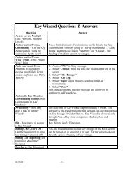
2.37 KEY MANAGEMENT SOFTWARE<br />
A. Provide Key Wizard‚ key management software.<br />
B. Software shall provide tracking, issuing, collecting and transferring information regarding keys,<br />
doors, and hardware.<br />
C. Provide training for Owner’s personnel on the proper operation and application of the key<br />
management software.<br />
2.38 FASTENERS<br />
A. Including, but not limited to, wood or machine screws, bolts, bolts, nuts, anchors, etc. of proper<br />
type, material, and finish required for installation of hardware.<br />
B. Use phillips head for exposed screws. Do not use aluminum screws to attach hardware.<br />
C. Provide self-tapping (TEC) screws for attachment of sweeps and stop-applied weatherstripping.<br />
2.39 TYPICAL FINISHES AND MATERIALS<br />
A. Finishes, unless otherwise specified:<br />
1. Butts: Outswinging Exterior Doors<br />
a. US32D (BHMA 630) on Stainless Steel<br />
2. Butts: Interior Doors and Inswinging Exterior Doors<br />
a. US26D (BHMA 652) on Steel<br />
<strong>Sargent</strong><br />
Hardware<br />
09/08/03 <strong>08710</strong> - 13
3. Continuous Hinges:<br />
a. US28 (BHMA 628) on Aluminum<br />
4. Flush Bolts:<br />
a. US26D (BHMA 626) on Brass or Bronze<br />
5. Exit Devices:<br />
a. US32D (BHMA 630) on Stainless Steel<br />
6. <strong>Locks</strong> and Latches:<br />
a. US26D (BHMA 626) on Brass or Bronze<br />
7. Push Plates, Pulls and Push Bars:<br />
a. US32D (BHMA 630) on Stainless Steel<br />
8. Coordinators:<br />
a. USP (BHMA 600) on Steel<br />
9. Kick Plates, Armor Plates, and Edge Guards:<br />
a. US32D (BHMA 630) on Stainless Steel<br />
10. Overhead Stops and Holders:<br />
a. US26D (BHMA 626) on Brass or Bronze<br />
11. Closers: Surface mounted.<br />
a. Sprayed Aluminum Lacquer.<br />
12. Latch Protectors:<br />
a. US32D (BHMA 630) on Stainless Steel<br />
13. Miscellaneous Hardware:<br />
a. US26D (BHMA 626) on Brass or Bronze<br />
PART 3 EXECUTION<br />
3.1 EXAMINATION<br />
A. Examine doors, frames, and related items for conditions that would prevent the proper<br />
application of finish hardware. Do not proceed until defects are corrected.<br />
3.2 INSTALLATION<br />
A. Install finish hardware in accordance with reviewed hardware schedule and manufacturer's<br />
printed instructions. Prefit hardware before finish is applied, remove and reinstall after finish is<br />
completed. Install hardware so that parts operate smoothly, close tightly and do not rattle.<br />
B. Installation of hardware shall comply with NFPA 80 and NFPA 101 requirements.<br />
C. Set units level, plumb and true to line and location. Adjust and reinforce attachment to<br />
substrate as necessary for proper installation and operation.<br />
D. Drill and countersink units which are not factory-prepared for anchorage fasteners. Space<br />
fasteners and anchors in accordance with industry standards.<br />
E. Set thresholds for exterior doors in full bed of butyl-rubber or polyisobutylene mastic sealant,<br />
forming tight seal between threshold and surface to which set. Securely and permanently<br />
anchor thresholds, using countersunk non-ferrous screws to match color of thresholds<br />
(stainless steel screws at aluminum thresholds).<br />
F. Lead Protection: Lead wrap hardware penetrating lead-lined doors. Levers and roses to be<br />
lead lined. Apply kick and armor plates with 3M adhesive #1357, as recommended by 3M Co.,<br />
on lead-lined doors.<br />
3.3 FIELD QUALITY CONTROL<br />
A. After installation has been completed, provide services of qualified hardware consultant to<br />
check Project to determine proper application of finish hardware according to schedule. Also<br />
check operation and adjustment of hardware items.<br />
B. Adjust door control devices to compensate for final operation of heating and ventilating<br />
equipment.<br />
<strong>Sargent</strong><br />
Hardware<br />
09/08/03 <strong>08710</strong> - 14
3.4 ADJUSTING AND CLEANING<br />
A. At final completion, hardware shall be left clean and free from disfigurement. Make final<br />
adjustment to door closers and other items of hardware. Where hardware is found defective<br />
repair or replace or otherwise correct as directed.<br />
B. Adjust door closers to meet opening force requirements of Uniform Federal Accessibility<br />
Standards.<br />
C. Final Adjustment: Wherever hardware installation is made more than one month prior to<br />
acceptance or occupancy of space or area, return to work during week prior to acceptance or<br />
occupancy, and make final check and adjustment of hardware items in such space or area.<br />
Clean operating items as necessary to restore proper function and finish of hardware and<br />
doors.<br />
D. Instruct Owner's personnel in proper adjustment and maintenance of door hardware and<br />
hardware finishes.<br />
E. Clean adjacent surfaces soiled by hardware installation.<br />
3.5 PROTECTION<br />
A. Provide for proper protection of items of hardware until Owner accepts Project as complete.<br />
3.6 <strong>HARDWARE</strong> GROUPS<br />
A. The following schedule of hardware groups shall be considered a guide only, and the supplier<br />
is cautioned to refer to general conditions, special conditions, and the preamble to this section.<br />
It shall be the hardware supplier's responsibility to furnish all required hardware.<br />
B. Refer to the door schedule for hardware group required at each door opening. Ignore<br />
hardware groups not used on the door schedule.<br />
END OF <strong>SECTION</strong><br />
<strong>Sargent</strong><br />
Hardware<br />
09/08/03 <strong>08710</strong> - 15