A Class-AB Output Buffer for Driving High Capacitive Loads
A Class-AB Output Buffer for Driving High Capacitive Loads
A Class-AB Output Buffer for Driving High Capacitive Loads

You also want an ePaper? Increase the reach of your titles
YUMPU automatically turns print PDFs into web optimized ePapers that Google loves.
A <strong>Class</strong>-<strong>AB</strong> <strong>Output</strong> <strong>Buffer</strong> <strong>for</strong> <strong>Driving</strong> <strong>High</strong> <strong>Capacitive</strong> <strong>Loads</strong><br />
Mitra Mirhassani, Majid Ahmadi, William C. Miller<br />
The Research Centre <strong>for</strong> Integrated Microsystems<br />
University of Windsor, Windsor, Canada, N9B 3P4<br />
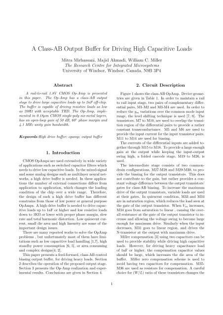
Abstract<br />
A rail-to-rail 1.8V CMOS Op-Amp is presented<br />
in this paper. The Op-Amp has a class-<strong>AB</strong> output<br />
stage to drive large capacitive loads up to 2nF off-chip.<br />
The buffer is capable of driving resistive loads as low<br />
as 200Ω with acceptable THD. The Op-Amp, implemented<br />
in 0.18µm CMOS single-poly six-metal layers,<br />
has an open-loop gain of 50 dB, 60 ◦ phase margin and<br />
4.1 MHz unity gain bandwidth.<br />
Keywords:<strong>High</strong> drive buffer; opamp; output buffer<br />
1. Introduction<br />
CMOS OpAmps are used extensively in wide variety<br />
of applications such as switched capacitor filters which<br />
needs to drive low capacitive loads. In the mixed-signal<br />
and some analog designs such as multilayer neural networks,<br />
a high drive buffer is needed. In these applications<br />
the number of external connections differs from<br />
application to application, which changes the loading<br />
condition of the chip over a wide range. There<strong>for</strong>e,<br />
the design of such a high drive buffer has different<br />
constrains from those of low power or general purpose<br />
OpAmps. A high drive buffer is needed to drive capacitive<br />
loads up to 1nF or higher and low resistive loads<br />
down to 1KΩ or lower with proper phase margin, slew<br />
rate and total harmonic distortion. Low quiescent current,<br />
small die area and high linearity are some of the<br />
important design issues.<br />
There are many reported works to solve the OpAmp<br />
problems , but un<strong>for</strong>tunately most of them have limitations<br />
such as low capacitive load handling [1,7], high<br />
standby power consumption [6, 5], or area consuming<br />
and complex designs[4, 2].<br />
This paper presents a feed-<strong>for</strong>ward, class-<strong>AB</strong> control<br />
biasing output buffer, <strong>for</strong> driving heavy loads. Section<br />
2 describes the operation of the proposed output stage.<br />
Section 3 presents the Op-Amp realization and experimental<br />
results. Conclusions are given in Section 4.<br />
2. Circuit Description<br />
Figure 1 shows the class-<strong>AB</strong> OpAmp. Device geometries<br />
are given in Table 1. In order to maintain a rail<br />
to rail input stage, two pairs of complementary differential<br />
pairs, M1-M2 and M3-M4 are used. In order to<br />
reduce the g m variations over the common mode input<br />
range, the level shifting technique is used [7, 8]. The<br />
transistors, M7 to M10, are used to overlap the transition<br />
region of the differential pairs to provide a rather<br />
constant transconductance. M5 and M6 are used to<br />
provide the input current <strong>for</strong> the input transistor pairs.<br />
M11 to M14 are used <strong>for</strong> biasing.<br />
The currents of the differential inputs are added together<br />
through M15 to M18. To provide a large enough<br />
gain at the output while keeping the input-output<br />
swing high, a folded cascode stage, M19 to M26, is<br />
used.<br />
The intermediate stage consists of two commondrain<br />
configurations, M27-M28 and M29-M30, to provide<br />
the biasing <strong>for</strong> the output transistors. This does<br />
not contribute to the gain, but rather provides a constant<br />
voltage difference between the output transistors’<br />
gates <strong>for</strong> class-<strong>AB</strong> biasing. To increase the maximum<br />
drive of the output transistors, variable loads are used<br />
at their gates. In quiescent condition, M33 and M34<br />
are in saturation region, which reduces the load seen at<br />
the gate of the output transistor. When V in increases,<br />
M34 goes from saturation to linear , causing the overall<br />
resistance at the gate of the output transistor to increase<br />
and allowing the voltage swing to become large<br />
enough <strong>for</strong> maximum drive. Similarly when the input<br />
decreases, M31 goes to linear region, and drives the<br />
N-transistor at the output with maximum drive.<br />
Miller compensation [3] using two capacitors can be<br />
used to provide stability while driving high capacitive<br />
loads. However, <strong>for</strong> driving heavy capacitance load<br />
of 1nF or higher, the compensation capacitor values<br />
should be large, which increases the die area of the<br />
buffer. Miller zero compensation scheme is used to<br />
avoid having two capacitors <strong>for</strong> compensation. M35-<br />
M36 are used as resistors <strong>for</strong> compensation. A careful<br />
choice <strong>for</strong> (W/L) ratio of these transistors changes the<br />
1
Figure 1: Full schematic of Op-Amp circuit<br />
related poles and zeros of the system to maintain an<br />
acceptable gain and phase margin. These transistors<br />
also reduce the impedance seen at the gates of the output<br />
transistors, and shift the poles generated by C gd<br />
of the output transistors to the higher frequencies. A<br />
compensation capacitor of 0.7pF is used which is a relatively<br />
small capacitor. The proposed output stage has<br />
a compact structure with good control on the quiescent<br />
current and drive capability.<br />
3. Experimental Results<br />
The buffer was realized in a 0.18µ single-poly six<br />
metal p-well CMOS process. The design occupied<br />
4136µm 2 . Simulations showed that the g m variation<br />
was within ±5% by using this technique. Figure 2 illustrates<br />
the output voltage when common mode input<br />
is changing from 0 to 1.8V.<br />
Figure 3 shows the push and pull currents of the<br />
output transistors. The (W/L) ratio of the output<br />
NMOS is 18/0.7 and that of the PMOS is 81/0.7. The<br />
quiescent current is only 18µA, while the push or pull<br />
current of the output transistors is about 760µA.<br />
The buffer has good phase margin <strong>for</strong> capacitive<br />
loads from 27pF up to 2nF. Figure 4 shows the magnitude<br />
and phase responses of the buffer while driving<br />
a 2nF capacitive load. It has 60 ◦ phase margin, openloop<br />
gain of 50dB and 4.1MHz unity gain bandwidth.<br />
The circuit is able to drive loads as low as 2KΩ from<br />
rail to rail. Figure 5 illustrates the measured output<br />
voltage when the differential input is swept between<br />
Figure 2: Op-Amp output voltage variations<br />
Figure 3: Push and pull currents of the output transistors<br />
2
Figure 4: Magnitude and phase response <strong>for</strong> a 2nF<br />
load<br />
-100mV and 100mV <strong>for</strong> two different resistive loads of<br />
10KΩ and 200Ω. DC offset voltage is 150µV . Total<br />
harmonic distortion when 1KHz sine wave with 1V p-<br />
p was applied to the buffer while driving a 200Ω load<br />
was 0.2%.<br />
Figure 6: Transfer characteristics of the opamp with<br />
different resistive loads<br />
Figure 7: Pulse response <strong>for</strong> 2nF load<br />
Figure 5: Measured output DC voltage<br />
The Op-Amp was used in a unity-gain follower<br />
configuration. Figure 6 shows the transfer characteristics<br />
of the buffer <strong>for</strong> two different loads of 10KΩ and<br />
200Ω. With loads as low as 200Ω output swing is still<br />
around 80% of the power supply.<br />
A 1V pulse step input has been applied to the Op-<br />
Amp in the unity gain follower configuration. No oscillations<br />
were observed as shown in Figure 7 <strong>for</strong> a 10KΩ<br />
and 2nF load, which ensures the stability of the buffer.<br />
The slew rate of the Op-Amp while driving 2nF capacitive<br />
and 10KΩ resistive load was 0.7 V/µs. The slew<br />
rate is up to 5V/µs <strong>for</strong> capacitive loads as low as 40pF<br />
and 10KΩ resistive load.<br />
Figure 8: <strong>Buffer</strong> layout<br />
3
4. Conclusion<br />
A 1.8V CMOS Op-Amp with constant g m and railto-rail<br />
input and output stages was reported. Op-Amp<br />
was realized in 0.18µm single-poly six-metal layers p-<br />
well CMOS process. The simulation results showed the<br />
stability of the Op-Amp <strong>for</strong> a wide range of capacitive<br />
loads. A high ratio between the maximum and quiescent<br />
currents was observed. The low quiescent current<br />
of only 18µA makes this circuit a suitable choice <strong>for</strong><br />
low-power mixed-signal designs.<br />
Transistor (W/L) ratio<br />
M 1 , M 2 12/0.7<br />
M 3 , M 4 48/0.7<br />
M 5 , M 11 4/0.7<br />
M 6 , M 13 10/0.7<br />
M 7 , M 9 7/0.32<br />
M 8 , M 10 1/0.32<br />
M 12 0.5/1.1<br />
M 14 1.8/2.3<br />
M 15 , M 16 , M 17 , M 18 5/0.7<br />
M 19 , M 20 6/0.7<br />
M 21 , m 22 4/0.7<br />
M 23 , M 24 7/0.7<br />
M 25 , M 26 7/0.7<br />
M 27 10/0.7<br />
M 28 20/0.7<br />
M 29 15/0.7<br />
M 30 8/0.7<br />
M 31 , M 32 3/0.7<br />
M 33 , M 34 10/0.7<br />
M 35 0.4/14<br />
M 36 0.4/10<br />
M 37 18/0.7<br />
M 38 90/0.7<br />
Table 1- Transistors aspect ratios<br />
Acknowledgment<br />
The authors acknowledge the financial support provided<br />
by the Mircronet and the CMC <strong>for</strong> providing the<br />
CAD tools <strong>for</strong> this project.<br />
References<br />
[1] F. Bahmani and S. M. Fakhraie and A. Khakifirooz, ”A<br />
rail-to-rail constant gm 1V CMOS Op-Amp,” Proc. ISCAS<br />
2000, 669-672, 2000.<br />
[2] J. H. Botma and R. J. Wiegerink and S. L. J. Gierkink<br />
and R. F. Wassenaar, ”Rail to rail constant Gm input<br />
stage and class <strong>AB</strong> output stage <strong>for</strong> low-power CMOS<br />
OpAmps,” Analog integrated circuits and signal<br />
processing, vol. 6, 122-132, 1994.<br />
[3] R. Hogervorst, ”Low-voltage, low-power CMOS<br />
operational amplifier cells,” Coronet Books, 1996.<br />
[4] R. Hogervost and R. J. Wiegerink and P. A. L. de Jong<br />
and J. Fonderie and R. F. Wassenaar and J. H. Huijsing,<br />
”CMOS low-voltage operational amplifier with constant<br />
Gm and rail to rail input stage,” Proc. Int. Symposium<br />
on Circuits and Systems (ISCAS), 2876-2879, 1992.<br />
[5] M. D. Pardon and M. G. Degrauwe, ”A rail-to-rail<br />
Input/output CMOS amplifier,” IEEE Journal of Solid<br />
State Circuits, vol. 25, no. 2 501-504, 1990.<br />
[6] G. A. Rincon-Monro and R. Stair, ”A low-voltage<br />
rail-to-rail class <strong>AB</strong> CMOS amplifier with high drive and<br />
low output impedance characteristics,” IEEE Trans.<br />
Circuits and Systems II: Analog and Digital Signal<br />
Processing, vol. 48, no. 8, 753-761, 2001.<br />
[7] M. Wang and T. L. Mayhugh and S. H. K. Embabi<br />
and E. Sanchez-Sinencio, ”Constant g m rail-to-rail CMOS<br />
Op-Amp input stage with overlapped transition regions,”<br />
IEEE Journal of Solid-State Circuits, vol. 34, no. 2,<br />
148-156, 1999.<br />
[8] Shouli Yan and E. Sanchez-Sinencio, ”Low voltage<br />
analog circuit design techniques: A tutorial,” Invited<br />
paper, IEICE Trans. Analog Integrated Circuits and<br />
Systems, vol. E00-A, no. 2, 2000.<br />
[9] N. Yazdi and M. Ahmadi and G. A. Jullien and M.<br />
Shridhar, ”A high-dynamic range CMOS buffer amplifier<br />
with high drive capability,” Proc. ISCAS 92, vol.<br />
5,2332-2335, 1992.<br />
4