Construction joints - Ideal Joint System. - Ideal Work
Construction joints - Ideal Joint System. - Ideal Work
Construction joints - Ideal Joint System. - Ideal Work

Create successful ePaper yourself
Turn your PDF publications into a flip-book with our unique Google optimized e-Paper software.
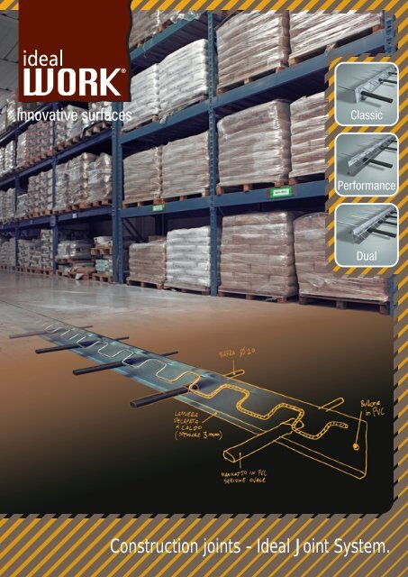
<strong>Construction</strong> <strong>joints</strong> - <strong>Ideal</strong> <strong>Joint</strong> <strong>System</strong>.
Problems connected to traditional <strong>joints</strong>.<br />
What are construction <strong>joints</strong>?<br />
<strong>Construction</strong> <strong>joints</strong> are used in slabs-on-grade to allow slab movement at transitional load bearing points from one<br />
concrete slab to the next. Traditional construction <strong>joints</strong> are considered worldwide as the Achilles’ heel of concrete<br />
slab placement (roads, airports, industrial and commercial floors). Concrete slabs-on-grade are subject to different<br />
internal and external forces and pressures. <strong>Joint</strong> deterioration occurs through load bearing weight transferring from<br />
one side of the joint to the other causing micro-shocks at the point of load cycle. In summary, a true construction<br />
joint must allow relative horizontal transition which is typically due to the thermal expansion and contraction or<br />
humidity induced shrinkage. At the same time it must not allow relative vertical transition and relative rotation due<br />
to traffic movement and load bearing weights. Figure 1 summarises the relative movements that a construction joint<br />
is subject to in a slab-on-grade.<br />
Fig. 1<br />
<strong>Joint</strong><br />
Fig. 3<br />
A joint must not allow<br />
relative vertical transition<br />
A joint must allow relative<br />
horizontal transition<br />
Fig. 2<br />
Relative<br />
vertical<br />
transition<br />
Fracturing and<br />
spalling<br />
Tyre<br />
Typical collapse<br />
due to a badly<br />
placed construction<br />
joint<br />
Example of construction joint demaged after a few<br />
months of life<br />
The absence or improper use of a construction joint will lead to slab failure with continual defects and joint deterioration<br />
due to the relative horizontal, vertical and rotational strains and pressures. Continual vehicular traffic transferring<br />
over a badly placed construction joint will cause fracturing and spalling (Figures 2 & 3). Rectifying these problems<br />
afterwards can be very costly and in some cases the entire concrete slab may need to be destroyed and replaced.<br />
Using the patented <strong>Ideal</strong> <strong>Joint</strong> systems will offer long term benefits and cost savings for every slab-on-grade project.
Traditional methods for a construction joint.<br />
The most common solution for a construction joint is the one referred to as a dowel joint system. It is constructed<br />
with steel rods approximately 400mm long and 20mm in diameter; they are placed through the concrete form work<br />
every 600mm perpendicular to the plane of the slab.<br />
Ensuring the correct placement of doweled <strong>joints</strong> requires a lot of time and effort. Often, through the lack of care<br />
and placing the steel dowels unevenly in spacing or at the incorrect angle, joint failure is inevitable causing long<br />
term damage to the joint and slab-on-grade (Figure 5).<br />
Fig. 4 Fig. 6 cracks<br />
Lack of alignment of dowel bars<br />
in a construction joint cast with<br />
partial formwork<br />
Cracks caused by a lack of<br />
alignment of the dowel bars<br />
Dowel bar<br />
Fig. 5<br />
Example of incorrect fabrication<br />
of a construction joint<br />
Fig. 7<br />
Cracks<br />
Damage caused by partial<br />
formwork<br />
Concrete spillage under a partial formwork<br />
Even if the dowel joint is positioned correctly they are usual knocked out of place and moved during the concrete<br />
placement (Figure 4). The fact that the steel dowels have moved will greatly reduce the support that they were<br />
intended to give to the joint<br />
The dowel bars that are misplaced or out of line now increase the risk of cracking the actual concrete (Figure 6).<br />
An irregular surface between the two sides of the construction joint will produce uneven load transfer and slab<br />
movement, which in turn produces weak points allowing cracks to appear in the slab (Figure 7).<br />
Where to place the steel mesh or welded steel.<br />
When concrete slab-on-grade needs to be re-enforced with steel mesh it is important that the mesh is placed in<br />
the correct area of the concrete slab. Placement of the steel mesh through the construction joint is a very common<br />
mistake and can potentially cause cracks and failure (Figure 8a). Correct placement for the steel mesh should be<br />
placed one third of the slab’s thickness starting from the upper section of the slab-on-grade (Figure 8b).<br />
Fig. 8 a<br />
Crack<br />
Fig. 8 b<br />
Wrong placement<br />
of the steel mesh<br />
h/3<br />
2h/3<br />
Correct placement<br />
of the steel mesh<br />
Placement of the steel mesh through the construction joint
<strong>Ideal</strong> <strong>Work</strong><br />
construction joint:<br />
“The joint that slides”<br />
Fig. 9<br />
Integrated fixed brackets for the steel<br />
mesh to be placed on<br />
PVC oval shaped dowel<br />
sleeve protector.<br />
Dowel bar ø 18-20 mm<br />
L = 600-800 mm<br />
PVC connector<br />
Technical connection to<br />
another joint section<br />
using the special PVC<br />
screws<br />
L-shaped 3mm steel<br />
IDEAL WORK has the solution for performing the perfect construction joint that has addressed all the previously<br />
mentioned construction joint issues. IDEAL JOINT SYSTEM ® has been carefully designed and developed to offer<br />
engineers, specifiers and contactors the most innovative construction joint in the flooring industry today.<br />
The IDEAL JOINT SYSTEM ® will distribute load transfer evenly allowing horizontal, and lateral movement between<br />
each independent section of the slab-on-grade.<br />
Fig.10<br />
Fig.11<br />
Detail of <strong>Ideal</strong> <strong>Joint</strong> <strong>System</strong> ® installed and ready for the concrete<br />
placement<br />
Detail of <strong>Ideal</strong> <strong>Joint</strong> <strong>System</strong> ® ready for the next placement of concrete .<br />
03
<strong>Ideal</strong> <strong>Work</strong> patent.<br />
Fig. 12<br />
PVC connector plays several roles:<br />
- it is the assembly element for the two<br />
independent steel forms<br />
- It is a guide for the dowel bar to slide<br />
comfortably through the metal forms into the<br />
PVC oval shaped dowel sleeve protector.<br />
PVC oval shaped<br />
dowel sleeve protector.<br />
How It <strong>Work</strong>s.<br />
IDEAL JOINT SYSTEM ® makes something really complicated very easy. A fixed dowel bar system does not allow<br />
any bidirectional movement of adjacent slabs-on-grade (Figures 17a & 17b). The patented PVC connector plays<br />
several roles in the IDEAL JOINT SYSTEM ® . First, the PVC screw connector is the assembly element for the two<br />
independent steel forms separating the actual slabs-on-grade. Secondly, it is a guide for the dowel bar to slide<br />
comfortably through the metal forms into the PVC oval shaped dowel sleeve protector. Once the concrete has<br />
hardened the hydration and early concrete stresses will snap the external connection frame of the PVC guide, leaving<br />
the joint free for movement (Figures 14a & 14b). Once the horizontal, vertical and lateral movement begins the internal<br />
connection framework of the PVC connector will collapse, allowing total independent movement (Figures 15a & 15b).<br />
Fig. 14a<br />
Fig. 15 a<br />
Sections of the PVC oval shaped dowel sleeve protector.<br />
dowel bar<br />
Break point<br />
Fig. 14b<br />
Fig. 15 b<br />
Once the horizontal, vertical and lateral movement begins<br />
the internal connection framework of the PVC connector<br />
will collapse, allowing horizontal movement.<br />
dowel bar<br />
04
Why PVC?<br />
To find a workable balance between structural requirements and simple installation, many concepts were considered.<br />
It was necessary to make the installation simple and with as few stages on the job site as possible to reduce the<br />
risk of making forgetful mistakes (See the table listing other methods). Most other methods are hand crafted and<br />
simple steps, like making a construction joint, can be easily forgotten or ignored. 95% of the IDEAL JOINT SYSTEM ®<br />
is pre-manufactured and ready for simple placement on the job site. The actual installation is the further 5%; placing<br />
the dowel bars and one simple PVC screw.<br />
Fig. 16 a<br />
Fig. 16 b<br />
Fig. 17 a<br />
Fig. 17 b<br />
Cracks<br />
Cracks<br />
Dowel bars<br />
Traditional<br />
construction<br />
joint<br />
Example of problems connected to traditional<br />
construction joint<br />
Horizontal movements<br />
not allowed<br />
Cracks caused by the horizontal<br />
movements not allowed<br />
Cracks<br />
Traditional<br />
construction joint<br />
Cracks due to intersection of two<br />
traditional construction <strong>joints</strong><br />
Correct placement of steel mesh or welded steel.<br />
To solve the problem of the steel mesh being positioned incorrectly the IDEAL JOINT SYSTEM ® has integrated fixed<br />
brackets for the steel mesh to be placed on (Figure 18). The integrated fixed brackets are exactly positioned one<br />
third from the top of the IDEAL JOINT SYSTEM ® to ensure the steel mesh is correctly placed. IDEAL JOINT SYSTEM ®<br />
has a full technical specification written by engineer ROBERTO TROLI from ENC Lab (The Laboratory approved by<br />
the Ministry of Public <strong>Work</strong>s and certified by the Ministry of the Universities and Research in Science and Technology)<br />
and technical documentation written by RENZO AICARDI, former member of the Executive Board CON.PAV.I. (Italian<br />
Association of Industrial Floors) and now technical manager of ENCOPER (National Agency of Manufacturing<br />
Pavements and Coatings).<br />
Fig. 18<br />
The integrated fixed brackets<br />
are exactly positioned one<br />
third from the top of the IDEAL<br />
JOINT SYSTEM® to ensure<br />
the steel mesh is correctly<br />
placed.<br />
05
Application fields.<br />
IDEAL JOINT SYSTEM ® is specially designed to withstand continual use from heavy traffic such as forklift trucks<br />
with wheels that are highly destructive to incorrectly formed construction <strong>joints</strong>.<br />
Main fields of application:<br />
• Industrial floors<br />
• Heavy Industries<br />
• Logistics<br />
• Exhibition Halls<br />
• Distribution centers<br />
• Shopping Centres<br />
• Airports<br />
• Docks<br />
Underfloor heating.<br />
IDEAL JOINT SYSTEM ® can also be used for floors that require radiant or under floor heating systems (Figure 19).<br />
Fig. 19<br />
Exterior flooring.<br />
External construction <strong>joints</strong> have different requirements to internal construction <strong>joints</strong>. Exposure to a wider range<br />
of temperatures and other weather related issues such as rain, snow and ice need to be considered when specifying<br />
construction <strong>joints</strong>. High temperatures cause slabs-on-grade to expand; if the construction joint has not been<br />
correctly designed to allow for this excessive movement then spalling and cracking may appear (Figures 20b & 20c).<br />
IDEAL JOINT SYSTEM ® offers the flooring engineer a simple solution to allow for excessive thermal heat expansion,<br />
simply by adding extra isolation foam between the two independent steel forms (4mm isolation foam to 12mm<br />
isolation foam) (Figure 20a). Another consideration for external use is the galvanised option on the steel forms for<br />
optimal protection against frost and winter slat erosion (Galvanized steel forms not dowel bars).<br />
Fig. 20 a<br />
Extra isolation foam<br />
between the two<br />
independent steel<br />
forms (4mm isolation<br />
foam to 12mm<br />
isolation foam)<br />
Fig. 20 b<br />
<strong>Construction</strong> joint<br />
Fig. 20 c<br />
<strong>Construction</strong> joint<br />
damaged by excessive<br />
thermal heat expansion<br />
06
<strong>Ideal</strong> <strong>Work</strong> <strong>Joint</strong>s.<br />
Individual construction <strong>joints</strong> for individual criteria.<br />
IDEAL WORK has developed an entire range of preformed construction <strong>joints</strong> to meet and solve all the criteria for<br />
the design of construction <strong>joints</strong> for slab-on-grade specifications.<br />
Each of these <strong>joints</strong> offer different solutions to individual project requirements, whilst maintaining the multi directional<br />
movement and easy to use characteristics shared throughout all IDEAL JOINT SYSTEMS ® .<br />
IDEAL JOINT SYSTEM ® CLASSIC<br />
The first joint system to be developed and it is still the most<br />
used joint system by far.<br />
• The most popular multipurpose construction joint<br />
• Pre-manufactured and ready to use<br />
• Available in standard steel or galvanized finish<br />
• 100mm steel form depth with 25mm increments to 250mm<br />
• Custom <strong>joints</strong> deeper than 250mm can be made to special order<br />
IDEAL JOINT SYSTEM ® PERFORMANCE<br />
Additional reinforcement for use in areas that are subject to increased<br />
heavy traffic.<br />
• High impact and abrasion joint reinforcement bar<br />
• Heavy traffic location, airports, gas stations, farmyards<br />
• Pre-manufactured and ready to use<br />
• 100mm steel form depth with 25mm increments to 250mm<br />
• Custom <strong>joints</strong> deeper than 250mm can be made to special order<br />
IDEAL JOINT SYSTEM ® DUAL<br />
Designed for interior projects such as shopping malls, exhibition<br />
centres and other areas where the construction joint needs to be<br />
higher than the concrete ready to accept marble, granite, tile or other<br />
finished products.<br />
• Allows one continual joint from the construction joint to the<br />
finished floor joint<br />
• Pre-manufactured and ready to use<br />
• 100mm steel form depth with 25mm increments to 250mm<br />
• Custom <strong>joints</strong> deeper than 250mm can be made to special order<br />
07
<strong>Ideal</strong> <strong>Joint</strong> <strong>System</strong> ® Classic.<br />
IDEAL JOINT SYSTEM ® CLASSIC is suitable for all types of industrial flooring and should replace any traditional<br />
hand crafted dowel joint systems. It can also be used as isolation <strong>joints</strong> or as control <strong>joints</strong> to separate individual<br />
pours as part of a flooring design allowing all the <strong>joints</strong> to have the same appearance. This reduces the need for<br />
saw cutting and risking thermal cracking during the hydration period.<br />
IDEAL JOINT SYSTEM ® CLASSICis made from two L-shaped 3mm steel forms joined via the unique hardened plastic<br />
connectors. The top of the steel L-shaped forms incorporates a V-shaped flared opening. The V-shaped opening<br />
offers higher impact resistance and larger surface area for joint sealing with traditional silicone mastic or polyurethane.<br />
The only joint system that is sold and delivered ready to use; simply put the joint in place and slide in the dowel<br />
bars. The special oval shaped connection and dowel bar sleeve have been calibrated to optimise the performance<br />
for horizontal and lateral movement for load transfer.<br />
T - connection<br />
L2<br />
L1<br />
R<br />
L<br />
X - connection<br />
S<br />
ø<br />
B<br />
L2<br />
L1<br />
L1<br />
H<br />
L2<br />
Code<br />
H<br />
(mm)<br />
Ø Dowel<br />
bars (mm)<br />
B<br />
(mm)<br />
Weight<br />
(Kg)*<br />
Features<br />
IJS-100 100 18 600 32,91<br />
IJS-100Z 100 18 600 32,91 Galvanized<br />
IJS-125 125 18 600 33,24<br />
IJS-125Z 125 18 600 33,24<br />
IJS-150 150 18 600 39,90<br />
IJS-150Z 150 18 600 39,90<br />
Galvanized<br />
Galvanized<br />
T and X connections<br />
Code<br />
T X<br />
IJS-100-T IJS-100-X<br />
IJS-125-T IJS-125-X<br />
IJS-150-T IJS-150-X<br />
IJS-175-T IJS-175-X<br />
height<br />
(mm)<br />
100<br />
125<br />
150<br />
175<br />
L1<br />
(mm)<br />
250<br />
250<br />
250<br />
250<br />
L2<br />
(mm)<br />
300<br />
300<br />
300<br />
300<br />
Weight (Kg)<br />
T X<br />
3,85 7,70<br />
4,40 8,80<br />
5,00 10,00<br />
5,55 11,10<br />
IJS-175 175 18 600<br />
IJS-175Z 175 18 600<br />
44,91<br />
44,91<br />
Galvanized<br />
<strong>Ideal</strong> <strong>Joint</strong> Classic<br />
Section<br />
IJS-200 200 20 800<br />
48,09<br />
IJS-200Z 200 20 800<br />
48,09<br />
Galvanized<br />
IJS-225 225 20 800<br />
54,09<br />
IJS-225Z 225 20 800<br />
54,09<br />
Galvanized<br />
IJS-250 250 20 800<br />
60,12<br />
Concrete floor.<br />
IJS-250Z 250 20 800<br />
60,12<br />
Galvanized<br />
L = 3000mm (Length of a single joint)<br />
R = 500mm (Distance between dowel bars)<br />
S = 32mm (Maximum lateral movement allowed)<br />
* Weight of the assembled joint, dowel bars included<br />
<strong>Ideal</strong> <strong>Joint</strong> system <strong>joints</strong> can be made on request with customized<br />
measurements decided by the <strong>Work</strong>s Management.<br />
Technical drawings in AutoCAD or JPG format can be downloaded directly from our website: www.idealwork.com<br />
08
<strong>Ideal</strong> <strong>Joint</strong> <strong>System</strong> ® Performance.<br />
IDEAL JOINT SYSTEM ® PERFORMANCE should be used in areas where heavy traffic is to be expected. Farmyards,<br />
airports and logistics centres are all places that experience abnormal heavy traffic and objects being dragged across<br />
the floor.<br />
IDEAL JOINT SYSTEM ® PERFORMANCE evolved from the CLASSIC joint system with the need for higher impact<br />
and abrasion. A wider, heavier grade of steel is used to form the top section of the L-shaped steel forms; this<br />
additional reinforcement offers the highest level of protection. The top of the steel form still maintains a V-shaped<br />
flared edge detail to optimise protection and larger surface area for joint sealing with traditional silicone mastic or<br />
polyurethane. The only joint system that is sold and delivered ready to use; simply put the joint in place and slide<br />
in the dowel bars. The special oval shaped connection and dowel bar sleeve have been calibrated to optimise the<br />
performance for horizontal and lateral movement for load transfer.<br />
Detail of the top reinforcement<br />
R<br />
L<br />
S<br />
ø<br />
B<br />
H<br />
Code<br />
H<br />
(mm)<br />
Ø Dowel<br />
bars (mm)<br />
B<br />
(mm)<br />
Weight<br />
(Kg)*<br />
Features<br />
IJS-PER125/6Z 125 18 600 31,45 6 mm top reinforcement galvanized<br />
IJS-PER150/6Z<br />
150 18 600 32,35 6 mm top reinforcement galvanized<br />
IJS-PER175/6Z<br />
175 18 600 33,25 6 mm top reinforcement galvanized<br />
IJS-PER200/6Z<br />
200 20 800 39,45 6 mm top reinforcement galvanized<br />
L = 3000mm (Length of a single joint)<br />
R = 500mm (Distance between dowel bars)<br />
S = 32mm (Maximum lateral movement allowed)<br />
<strong>Ideal</strong> <strong>Joint</strong> Performance - Section<br />
* Weight of the assembled joint, dowel bars included<br />
<strong>Ideal</strong> <strong>Joint</strong> system <strong>joints</strong> can be made on request<br />
with customized measurements decided by the <strong>Work</strong>s Management.<br />
Concrete floor.<br />
Technical drawings in AutoCAD or JPG format can be downloaded directly from our website: www.idealwork.com<br />
09
<strong>Ideal</strong> <strong>Joint</strong> <strong>System</strong> ® Dual.<br />
IDEAL JOINT SYSTEM ® DUAL is specifically design to be placed in concrete subfloors where the joint needs to be<br />
continued through for a finished product such as tile, marble, granite or travertine. DUAL IDEAL JOINT SYSTEM ®<br />
offers in one simple product the construction joint and the transfer joint to the final finished floor level. Utilising this<br />
unique characteristic in the construction of the subfloors eliminates the need for a secondary joint in the finished<br />
flooring and guarantees true joint alignment. DUAL: IDEAL JOINT SYSTEM ® is designed for use in shopping malls,<br />
museums, supermarkets and exhibition centres that require secondary floor finishes over the concrete subfloor.<br />
IDEAL JOINT SYSTEM ® DUAL works in the same manner as all our other joint systems. The addition of an aluminium<br />
attached frame that stands higher than the subfloor level is what gives the dual usage to the construction joint.<br />
IDEAL JOINT SYSTEM ® DUAL The only joint system that is sold and delivered ready to use; simply put the joint in<br />
place and slide in the dowel bars. The special oval shaped connection and dowel bar sleeve have been calibrated<br />
to optimise the performance for horizontal and lateral movement for load transfer.<br />
Detail of the aluminium<br />
attached frame<br />
R<br />
L<br />
S<br />
ø<br />
B<br />
H<br />
Code<br />
H<br />
(mm)<br />
Ø Dowel<br />
bars (mm)<br />
B<br />
(mm)<br />
Weight<br />
(Kg)*<br />
IJS-DUAL125 125 18 600 33,00<br />
IJS-DUAL150 150 18 600 35,40<br />
IJS-DUAL175 175 18 600 37,80<br />
IJS-DUAL200 200 20 800 45,30<br />
L = 3000mm (Length of a single joint)<br />
R = 500mm (Distance between dowel bars)<br />
S = 32mm (Maximum lateral movement allowed)<br />
* Weight of the assembled joint, dowel bars included<br />
<strong>Ideal</strong> <strong>Joint</strong> system <strong>joints</strong> can be made on request<br />
with customized measurements decided by the <strong>Work</strong>s Management.<br />
<strong>Ideal</strong> <strong>Joint</strong> <strong>System</strong> Dual<br />
section of concrete floor<br />
<strong>Ideal</strong> <strong>Joint</strong> <strong>System</strong> Dual<br />
section of tiles floor<br />
Tiles<br />
Concrete floor<br />
Sand-cement or self-levelling<br />
Concrete floor<br />
Technical drawings in AutoCAD or JPG format can be downloaded directly from our website: www.idealwork.com<br />
10
Benefits of using <strong>Ideal</strong> joint system.<br />
Benefits for the designer & engineers.<br />
• True dimensional characteristics<br />
• Perfect load bearing weight distribution<br />
• Standard depth specifications<br />
• Easy to translate from design to installation<br />
Benefits for the installer.<br />
• Quick and easy to install<br />
• Ready to use without additional parts needing assembly<br />
• Reduced installation labour costs<br />
• Stops concrete spillage under the joint<br />
• <strong>Joint</strong>s sealing can be performed the next day<br />
• Simple purchasing and shipping<br />
Benefits to the end user.<br />
• Reduced maintenance and repair costs<br />
• Reduced slab curling<br />
• Long term joint protection<br />
11
Specification items:<br />
<strong>Ideal</strong> <strong>Joint</strong> <strong>System</strong> Classic.<br />
Patented bi-directional construction/movement joint called <strong>Ideal</strong> <strong>Joint</strong> <strong>System</strong> Classic, height…………, consisting<br />
of two opposing L-shaped plates in 3 mm thick hot pickled plate joined together by screw-threaded PVC connectors<br />
and complete with bi-directional PVC sleeves, metal bars and reinforcement stringer. IDEAL JOINT SYSTEM –<br />
CLASSIC is supplied on site ready assembled in 3-metre sections, which, thanks to the relative undercut on the<br />
plates, can be easily joined together using the special PVC screws that are provided. On request by the <strong>Work</strong>s<br />
Management the flanges may be more widely spaced by the insertion of adhesive polyethylene foam covering to<br />
absorb thermal expansion.<br />
<strong>Ideal</strong> <strong>Joint</strong> <strong>System</strong> Performance.<br />
Patented bi-directional construction/movement joint called <strong>Ideal</strong> <strong>Joint</strong> <strong>System</strong> Performance, height…………, consisting<br />
of one plate in 3 mm thick hot pickled plate bent to a T shape, complete with bi-directional PVC sleeves, metal bars,<br />
double upper reinforcement plate fitted with adhesive polyethylene foam covering and reinforcement stringer. IDEAL<br />
JOINT SYSTEM – PERFORMANCE is supplied in 3-metre long modules that can be assembled with PVC screws.<br />
<strong>Ideal</strong> <strong>Joint</strong> <strong>System</strong> Dual.<br />
Patented bi-directional construction/movement joint called <strong>Ideal</strong> <strong>Joint</strong> <strong>System</strong>, height…………., consisting of two<br />
opposing L-shaped plates in 3 mm thick hot pickled plate, spaced apart by the insertion of adhesive polyethylene<br />
foam covering, complete with bi-directional PVC sleeves, metal bars and reinforcement stringer. A special aluminium<br />
section is anchored on top of the bars, which consists of three elements slotted together to allow both contraction<br />
and expansion movements between 3 and 10mm. The bars are joined together by screw-threaded PVC connector.<br />
IDEAL JOINT SYSTEM - DUAL is supplied on site ready assembled in 3-metre sections, which, thanks to the relative<br />
undercut on the plates, can be easily joined together using the special PVC screws that are provided.<br />
<strong>Ideal</strong> <strong>Joint</strong> system <strong>joints</strong> can be made on request with customised measurements decided by the <strong>Work</strong>s Management.<br />
N.B. The thickness and length of the bars and distance between them have been decided on the basis of the latest<br />
requirements reported in literature on concrete floors and recent studies carried out both in Italy and the USA.<br />
No part of this publication may be reproduced without the prior written permission of <strong>Ideal</strong> <strong>Work</strong> Srl. Any infringement<br />
will be prosecuted according to the law.<br />
Installation<br />
Positioning on the joint line.<br />
01<br />
Installation with PVC screws.<br />
02<br />
03<br />
Installation of the plastic sleeves and dowel<br />
bars.<br />
04 05 06<br />
Concrete placement.<br />
Finishing of the concrete slab.<br />
Concrete can be on both side of <strong>Ideal</strong><br />
<strong>Joint</strong>s at the same time or alternate days<br />
to separate two placements.<br />
12
<strong>Ideal</strong> <strong>Work</strong> working alongside<br />
designers and architects.<br />
An example of a “made-to-measure” <strong>Ideal</strong> <strong>Work</strong> joint<br />
The work involved the erection of three vertical adjoining warehouses for storing semi-finished and finished products,<br />
with an approx. total surface area of 5000 m2 and a height of 26 m.<br />
The load-bearing structure is in steel sections, which allows the installation of automatic systems for storage shelf<br />
handling. The foundation consists of a 90 cm thick reinforced concrete slab, a 10 cm thick non-reinforced floor<br />
rough, a 60 cm slab with double cross reinforcement and a 20 cm thick cement screed structurally bonded to the<br />
slab and reinforced with electrically welded mesh. The division into three adjoining warehouses and the expanse<br />
of the foundation slab meant dividing the floor into 15 sectors joined together by structural <strong>joints</strong>, which allow<br />
expansion along the horizontal axis avoiding differential movements along the vertical axis as is necessary for a steel<br />
construction. A hinged performance of the structural <strong>joints</strong> was taken into consideration in the calculation stage.<br />
The use of <strong>Ideal</strong> <strong>Joint</strong> 70 cm deep <strong>joints</strong> allowed the structural slab and the overlying floor to be made within the<br />
space of 12-16 hours with two separate “wet on wet” casts, thereby obtaining single slab structural performance.<br />
The thickness of the slab could therefore be reduced since the system provides monolithic performance while at<br />
the same time offering a high quality and aesthetic standard due to the total lack of macro or micro cracks.<br />
13
References.<br />
FIERA DI MILANO Milan<br />
SAN MARCO AIRPORT spa Venice<br />
BOCCONI UNIVERSITY ROOMS Milan<br />
THERMAL POWER PLANT Bando (FE)<br />
ADRIA MOTOR RACING CIRCUIT Adria (RO)<br />
COOP TORINO Turin Corso Umbria<br />
COOP NOVARA Novara<br />
COOP BORGOMANERO Borgomanero<br />
IPERMERCATO DESPAR Shopping mall Sant’Ilario (RE)<br />
TOGNANA PORCELLANE spa Casier (Tv)<br />
BARILLA spa - Warehouse Genoa<br />
GRUPPO BENETTON OLIMPIAS spa Villorba (TV)<br />
BENETTON spa Osiek (Croatia)<br />
LORO PIANA spa Romagnano Sesia (NO)<br />
GRAPPA NONNINO spa Udine<br />
ENICHEM spa Marghera (VE)<br />
SAN MARCO PETROLI spa Marghera (VE)<br />
COOP Costruzioni Budrio (Bo)<br />
HP CENTER spa (Motori Polini) Alzano Lombardo (BG)<br />
AUTOTRASPORTI GHIRARDI Alzano Lombardo (BG)<br />
LAICNER Vipiteno (BZ)<br />
RUBINETTERIA CIMBERIO spa Pogno (NO)<br />
RUBINETTERIA OTTONE & MELODA spa San Maurizio (NO)<br />
OCEAN spa Shipyard Monfalcone<br />
F.lli NASCIO Shipyard Casarsa Ligure<br />
PESCA MAR Valli di Chioggia<br />
BIOS LINE Ponte S. Nicolò (PD)<br />
FRIGOR REVISION Mestrino (PD)<br />
AERMACCHI Vengono Superiore (VA)<br />
COGEFRIN spa Castelmaggiore (BO)<br />
DANA spa Montano Lucino (Co)<br />
SERVOMECH Angola Emilia (Bo)<br />
S.A.M.M.O. spa Cesena<br />
GEOTEC Loreo Adria<br />
FABRIZIO OVIDIO FERRAMENTA spa Mansuè<br />
VETRERIA SACILESE Montereale (PN)<br />
PRISMA Ormelle (TV)<br />
CANTINA SOCIALE di PONTE DI PIAVE Ponte di Piave (TV)<br />
UNIFLAIR ITALIA Spa Conselve (PD)<br />
SAIMP spa Tradate (VA)<br />
GASCHET Castel di Caleppio (BG)<br />
RODADA Muggio (MI)<br />
BERTO PASQUALE Udine<br />
PERUSI Fruit and vegetables wholesale Sona (VR)<br />
AR.TI.CA. Arre (PD)<br />
MENON Lugagnano (VR)<br />
LAMINAM srl Fiorano Modenese (MO)<br />
FORGIALLUMINIO spa Pedavena Feltre (BL)<br />
BONALDO snc Galliera Veneta (PD)<br />
MASCHIETTO EREDI San Vendemiano (TV)<br />
STAMPIAVE San Polo di Piave (TV)<br />
AGRICOLA BAGNOLESE Arre (PD)<br />
TORRESIN Limena (PD)<br />
ARTIGIAN LEGNO Adrara S. Martino (BG)<br />
Le riproduzioni anche parziali di testi e foto sono<br />
vietate, se non autorizzate da <strong>Ideal</strong> <strong>Work</strong> Srl.<br />
Ogni violazione verrà perseguita a norma di legge.<br />
14